1
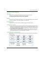
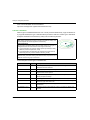
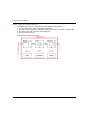
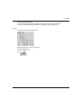
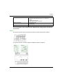
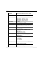
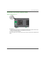
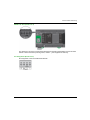
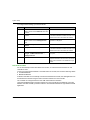
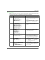
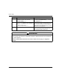
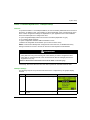
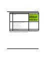
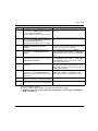
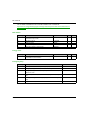
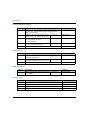
System Setup The configuration using the DTM feature inside SoMachine is described in the table. In this example one wireless and batteryless push-button has been assigned to a channel. Step 182 Action Comment 1 Add the device FDT Connections to the Devices The device must be added directly under the project tree in the Logic Builder of SoMachine. node of the Devices tree. 2 Add the device Modbus Serial Line Manager to The device must be added under the device node of the Devices tree in the Logic Builder. the device FDT Connections. 3 Add the device DTM ZBRN2 Advanced Settings The device must be added under the device node of to the Devices tree. the device Modbus Serial Line Manager. 4 Make the configuration settings in the device editor of the Modbus Serial Line Manager. 5 Set the address of the device you want to connect In the Address Table of the Modbus Serial Line Manager (Device Editor →Configuration → in the device editor of the Modbus Serial Line Address Table) you need to edit the address of the Manager. connected device. The changes must be validated by the Apply button. 6 Now you have 3 opportunities to proceed: Offline configuration (proceed with step 7) Upload the configuration from the device (proceed with step 11) Online configuration (proceed with step 12) - 7 Assign the wireless sensors via MAC address (radio device identifier) to the channels in the device editor of the DTM ZBRN2 Advanced Settings. Skip this step if you want to use the online autoteach function. In the Teach Screen tab of the DTM ZBRN2 Advanced Settings (Device Editor →Configuration →Teach Screen) you can enter the teach information manually or you can import an existing configuration. 8 Make the serial line configuration in the device editor of the DTM ZBRN2 Advanced Settings. In the Protocol Information tab of the DTM ZBRN2 Advanced Settings (Device Editor →Configuration →Protocol Information) you need to make the serial line settings for the device. Use the same parameter as set on the device because on download the settings in the device are overwritten by the values in this editor. 9 Set the input holding time in the device editor of the DTM ZBRN2 Advanced Settings. In the I/O Screen tab of the DTM ZBRN2 Advanced Settings (Device Editor →Configuration →I/O Screen) you can select the input holding time. This time determines the time how long the channel indicates TRUE after a received signal from the bound sensor. In the Configuration tab of the Modbus Serial Line Manager (Device Editor →Configuration → Configuration) you need to edit the Connection Type, the COM Port, and the Link Parameters. The changes must be validated by the Apply button. EIO0000001677 06/2014