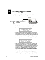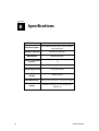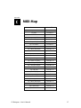
1
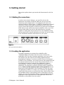
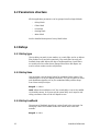
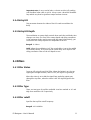
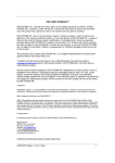
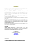
USER’S MANUAL
FX designer by
Chameleon Delay Based Effects Processor
revision 2 | 03.2003
www.soundart-hot.com
www.spinaudio.com
Copyright © 2001-2003 Soundart
www.soundart-hot.com
Soundart makes no warranty of any kind, expressed or implied, with respect to the contents or use
of the material in this document or in the software and hardware it describes, and specifically
disclaims any responsibility for any damages derived from its use. Hardware and Software may
contain design defects or errors known as errata which may cause the product to deviate from
published specifications. Soundart reserves the right to revise and modify the topics covered in this
document periodically, which are subject to change without notice. This document may be
reproduced and distributed freely, provided no alterations of any kind are made. Soundart software
is subject to the terms of the Soundart Tools Software license. Third party software is subject to the
terms of their respective owners license. Third party trademarks and registered trademarks are
property of their respective owners.
ii
Table of Contents
1
Introduction ................................................................
................................................................................................
................................................................ 4
1.1 Main features.........................................................................................4
1.2 Getting started.......................................................................................5
1.2.1 Making the connections ...........................................................5
1.2.2 Loading the application............................................................5
1.2.3 Loading the factory presets......................................................6
2
FX Designer concept ................................................................
...................................................................................
................................................... 7
3
Interface Reference ................................................................
....................................................................................
.................................................... 9
3.1 Menu Reference ....................................................................................9
3.2 Parameters structure.......................................................................... 10
3.3 Delays ................................................................................................. 10
3.3.1 Delay type.............................................................................. 10
3.3.2 Delay time.............................................................................. 10
3.3.3 Delay Feedback...................................................................... 10
3.3.4 Delay LFO................................................................................ 11
3.3.5 Delay LFO Depth .................................................................... 11
3.4 Filters................................................................................................... 11
3.4.1 Filter Status ............................................................................ 11
3.4.2 Filter Type............................................................................... 11
3.4.3 Filter cutoff............................................................................. 11
3.5 LFOs ..................................................................................................... 12
3.5.1 LFO Status............................................................................... 12
3.5.2 LFO Rate ................................................................................. 12
3.5.3 LFO Shape............................................................................... 12
3.5.4 LFO Phase ............................................................................... 12
3.6 Routing................................................................................................ 12
3.7 Mixer ................................................................................................... 13
3.7.1 Master Status ......................................................................... 13
3.7.2 Master Volumes ..................................................................... 13
3.7.3 Tap Status............................................................................... 13
3.7.4 Tap Gain ................................................................................. 13
3.7.5 Tap Pan................................................................................... 13
3.7.6 Tap 3DPan .............................................................................. 13
A
Loading Applications
Applications................................
................................................................
.................................................................................
................................................. 14
B
Specifications
Specifications................................
ons ................................................................
............................................................................................
............................................................ 16
C
MIDI Map ................................................................
................................................................................................
..................................................................
.................................. 17
D
Contact Information
Information................................
................................................................
..................................................................................
.................................................. 21
FX Designer – User’s Manual
iii
Chapter
11
Introduction
FX Designer is a professional audio multi-effects processor application
designed for Soundart’s Chameleon multipurpose digital audio platform.
The sound is processed using modern digital audio processing
algorithms taking benefit from the powerful DSP core running inside the
Chameleon.
FX Designer is a delay-based digital audio effects processor with a
flexible signal processing design that allows to produce such audio
effects as chorus, flanger, phaser, spatial effects, various reverbs and
any combination of above.
But FX Designer is not just for creation of well-known effects - it's
designed to create new, unheard before effects. Take an example: With
it it's possible to make a reverb that would sound like a room with sizes
changing over time!
To create all that variety of the effects FX Designer offers 6 modulated
delay lines with comb/allpass mode switch, 6 assignable LFOs and
flexible tap signal router that allows to interconnect taps into a network.
1.1 Main features
The main features of the FX Designer are:
4
-
Six modulated stereo delay lines with Comb/Allpass filter type
switch
-
Six assignable stereo LFOs with five waveforms and stereo shift
controls
-
Flexible tap signal routing
-
Low-Pass/High-Pass filter on each tap
-
High flexibility to edit effects parameters using the Chameleon
function keys and a logic menu structure
-
Comprehensible MIDI implementation allowing to modify
parameters using external MIDI controllers, record parameter
changes using a sequencer, and preset dumps and requests
-
Assignable Chameleon front panel realtime controllers to
virtually any sound parameter
Introduction
1.2 Getting started
This section explains how to get started with Chromasonic for the first
time.
1.2.1 Making the connections
In order to start using FX Designer, you need first to have the
Chameleon unit properly connected. Make sure that you have the
Chameleon power supply (9V DC/1.2A) plugged to the device and
connected to the AC mains. Figure 1-1 shows the Chameleon rear panel
connections. Before connecting the Chameleon to other units in the
system, ensure that the power to all units is off. Connect the Chameleon
audio inputs to your sound source outputs (amplifier, mixer, etc.). Now
connect audio cables from the left and right outputs to a suitable
amplifier or mixing desk stereo inputs (or use your headphones using
the front panel jack). Once all connections are made, turn on the power
of the Chameleon and all the other devices in your system.
Figure 1-1
Rear panel of the Chameleon.
1.2.2 Loading the application
FX Designer application is contained into a MIDI file called
“FXDesignerXXApp.mid” (where XX is the current version of the
application). Like any other Chameleon application, you have to take
care with the user data stored in the existing application before
downloading FX Designer. If you have an older version of FX Designer
installed in your Chameleon, your existing presets and configuration will
be properly updated to the new version once you download it, so it’s
not mandatory to make a backup of them (although it is always
recommended). If you have a different application installed in your
Chameleon, you may loose your data if you don’t make a backup of it
before. Please read the important notice in the Appendix A to learn
about how to load applications in the Chameleon in a safe way. Once
the application is loaded, it is ready to use. By default, the application
comes with all the presets set to the default state, with the three effect
units disabled. Before to start editing presets as described in the next
chapter, you may want to load the Factory presets distributed with the
application to take a quick overview of the application features and
possibilities, as described in the next section.
FX Designer – User’s Manual
5
1.2.3 Loading the factory presets
FX Designer factory presets come inside a MIDI file called
“FXDesignerXXFactory.mid” (where XX is the application version). You
will need a MIDI sequencer with a free MIDI output. When the
application is started, connect the output of your sequencer to the MIDI
input of the Chameleon. Then play the MIDI file containing the factory
presets and the presets will begin to load inside the Chameleon non
volatile memory. Once the Midi file finishes playing, presets will be
loaded. If you feed the Chameleon audio input with some audio signal,
you will hear how the sound is processed depending on the currently
active preset. To switch to another preset, move the encoder left or
right, or use the VALUE UP and DOWN keys.
NOTE: Factory presets can be edited, modified and overwritten like any
other preset, so all 128 available presets are considered as “user”
presets and there are not the so called “ROM presets”.
6
Introduction
Chapter
22
FX Designer concept
The main idea behind the plugin is provide an easy way to create
various delay based effects from the basic building blocks: comb and
allpass filters.
Comb filter is just a delay with a gained feedback loop. It produces a
series of exponentially decaying echoes. The decay time is determined
by the feedback gain.
Allpass filter is a delay that in addition to feedback loop like in comb
filter has also a feedforward loop. It also produces a series of
exponentially delaying echoes but every second echo has an inversed
phase.
Many audio effects like phaser, chorus, flanger, reverb, are made using
these two delay filter types. The table below outlines these differences.
Effect
type
Delay
range
Slap-back 50-100
delay
ms
Multi50-100
delays
ms
Multiple- 50-100
delays
ms
Chorus 20-40 ms
Delay
Delay filter Frequency Interconnection
Modulation type used
Filters
scheme
1 comb filter
Dry signal
required
no
comb
no
no
comb
no
no
comb
no
yes
comb
no
1 or more comb required if
filters running in- one comb
parallel
filter is used
Parallel comb
filters
Series of comb
filters
yes
yes
no
Flanger
0.5-15
ms
may be used
comb
no
1 or more comb
filters running inparallel
yes
Phaser
0.5-5
ms
yes
allpass
no
Series of allpass
filters
strictly
required
no
allpass,
comb
4 parallel comb
Low-Pass
filters followed by
filters may
a series of two
be used
allpass filters
no
allpass
Low-Pass
2 or more nested
filters may
allpass filters
be used
no
0.5-5 ms
Classic (allpass)
Reverb 1-100 ms
(comb)
Nestedallpass
reverb
0.5-100
may be used
ms
FX Designer – User’s Manual
7
The difference comes from how these blocks are inter-connected. For
example chorus and flanger can be made by one or more parallel comb
filters, phaser is a series of allpass filters and a basic reverb is a
combination of 4 parallel comb filters followed by a series of two allpass
filters. The effects also differ in the used delay time ranges and whether
or not the delays are modulated.
8
FX Designer concept
Chapter
33
Interface Reference
3.1 Menu Reference
FX Designer implements a controlling interface similar to all other
Soundart applications for Chameleon. The table below shows the menu
structure specific to FX Designer. Refer to their manuals for in-depth
description.
Group
Page
VOLUME
Parameter
Dry
Wet
Value
-96..0 dB
In
MASTER
Dry
STATUS
Wet
On/Off
In
MIX
DELAY
FILTER
ROUTING
LFO
MIDI
FX Designer – User’s Manual
TAP1..6
TAP1..6
TAP1..6
TAP1..6
OSC1..6
Status
On/Off
Gain
-96..0 dB
Pan
L -60 dB.. center.. R -60 dB
3DPan
R 100%.. center.. L 100%
Type
CB/AP
Time
1..100 ms
Feedback
0%..100%
LFO
Off/OSC1..OSC6
LFO Depth
0..100 ms
Status
On/Off
Type
LP/HP
Cutoff
100..16000 Hz
In
Master In/TAP1 Out..TAP6 Out
Out
Master Out/TAP1 In..TAP6 In
Status
On/Off
Rate
0..5 Hz
Shape
Sine/Tri/Sine^2/Sn+Sn2/Sn*Sn2
Phase
L 100%.. center.. R 100%
MidiChannel
1..16
MidiThru
On/Off
Midi ID
1..128
9
3.2 Parameters structure
All the application parameters can be grouped into five logical blocks:
-
Delays block
-
Filters block
-
LFOs block
-
Routing block
-
Mixer block
See the detailed description of every block below.
3.3 Delays
3.3.1 Delay type
The tap delay can work in two modes: as a comb filter and as an allpass
filter marked as CB and AP respectively. The comb filter has only one
feedback loop while allpass has also a feedforward loop. Comb filters
are mainly used to create chorus/flanger like effects and allpass are
used to create various reverbs and phasers.
3.3.2 Delay time
This parameter sets the lower bound for modulated delay sweep. The
sweep depth is set by LFO Depth parameter. So if you set delay to 20ms
and modulation depth to 40 ms, the modulated delay will be swept
from 20ms to 60(20+40)ms
Ranged: 1..100ms.
NOTE: When the modulation is off, the actual delay is set to the middle
of the delay sweep. So if you want the actual delay to be equal to the
delay parameter value set the LFO Depth to zero.
3.3.3 Delay Feedback
The amount of feedback signal that is mixed back to the tap input. For
low delay values the feedback makes the sound more harsh and
metallic.
Ranged: 0..100%.
10
Interface Reference
Important note: be very careful when, or better avoid at all, working
with feedback value close to 100%. It may create a dead lock feedback
loop which may lead to significant output volume increase.
3.3.4 Delay LFO
This parameter denotes the index of the LFO used to modulate the
delay.
3.3.5 Delay LFO Depth
The modulation or sweep depth controls how much the total delay time
changes over time. The sum of the sweep depth and delay parameters
is the maximum delay used in processing the signal. Alternatively, you
can think of the sweep depth as the amplitude of the LFO.
Ranged: 0..100ms.
NOTE: When the modulation is off, the actual delay is set to the middle
of the delay sweep. So if you want the actual delay to be equal to the
delay parameter value set the LFO Depth to zero.
3.4 Filters
3.4.1 Filter Status
Turns on/off using of tap LP/HP filter. When the button is on, the tap
signal goes through the filter, when it's off, the signal is bypassing it.
When the status is set to ON the signal from tap delay output goes
through the tap filter, when the status is OFF the signal bypasses the
filter.
3.4.2 Filter Type
There are two types of tap filter available: Low Pass marked as 'LP' and
High Pass marked as 'HP' respectively.
3.4.3 Filter cutoff
Specifies the tap filter cutoff frequency.
Ranged: 100..16000Hz.
FX Designer – User’s Manual
11
3.5 LFOs
3.5.1 LFO Status
Turns the corresponding LFO on/off. When LFO is turned off all the taps
referring to this LFO will stop modulate.
3.5.2 LFO Rate
This parameter refers to the rate at which the modulation waveform
oscillates.
Ranged: 0..5Hz.
3.5.3 LFO Shape
The LFO waveform defines how the delay changes over time. FX
Designer supports five waveforms: sinusoid, triangle, sinus squared,
sin2+(sinus with original rate plus sinus with double rate), sin2x(sinus
with original rate multiplied by sinus with double rate)
3.5.4 LFO Phase
Specifies phase shift between left and right stereo LFO channels.
Ranged: -100..100%.
3.6 Routing
The routing matrix is used to set up tap interconnection network. Each
tap has assignable input and output. The input can be tap1..tap6 or
plugin input and output can be tap1..tap6 or plugin output. To connect
two taps you need to specify only one link: either to set one tap output
to another tap or set one tap input to another tap. There is no need to
specify back link. For example if you set tap1 output to tap2, there is no
need to set tap2 input to tap1. If more than one tap are connected to
other tap input, then the signals are mixed at tap input.
12
Interface Reference
3.7 Mixer
3.7.1 Master Status
Switches on/off Input, Dry and Wet signals. Note that when you use FX
Designer in a send configuration you should turn the Dry signal off.
3.7.2 Master Volumes
Specifies the gains applied to Input, Wet and Dry signals.
3.7.3 Tap Status
Switches the tap on/off. Note that when a tap is off signal does not
pass through it.
3.7.4 Tap Gain
Specifies a gain applied to the signal at tap output. Ranges: -96 dB..0dB
3.7.5 Tap Pan
This is a conventional stereo pan. Ranges: 100%L..100%R
3.7.6 Tap 3DPan
This is a binaural pan. It's also called equal-power pan. Unlike
conventional stereo pan that creates panning effect by differential
gaining of left and right signals, binaural pan creates the panning effect
by introducing a small delay between left and right channel
FX Designer – User’s Manual
13
Appendix
A
Loading Applications
To load a new application or version update inside the Chameleon
follow the instructions below:
MIDI OUT
MIDI IN
Chameleon
SHIFT
MIDI Sequencer/ Player
-
The Chameleon must be powered ON with the SHIFT key
pressed, so the following screen will be displayed.
-
Connect the MIDI OUT of your MIDI Sequencer/Player machine
(for example, a computer with a MIDI interface) to the MIDI IN of
the Chameleon and Play the Application MIDI File containing the
new application or version update. It’s recommended to disable
the MIDI clock in the MIDI Sequencer/Player. If all is properly
connected, the following screen will be displayed showing an
increasing block counter.
-
When the counter arrives to the last block the Chameleon will
ask you to store the application in the internal Flash memory:
this must be confirmed by pressing the SHIFT key within the next
20 seconds in order to accept the received data. After pressing
the SHIFT key, the application will be burned in the internal
FLASH memory (never turn off the Chameleon during this
step)
If any problem happens during the downloading process, the
display will show “**BAD DATA**” or “**TIME OUT**”. To solve
this, try setting a lower tempo in the sequencer (i.e. 90 BPM)
14
Loading Applications
After the process has been successfully completed, the Chameleon will
power-up itself automatically, loading the new stored application, which
will need a few seconds to be fully operative after reconfiguring all the
internal resources to it’s needs (in this stage, if the Chameleon had
another application inside before loading the new one, the Presets of
the old application will be erased).
NOTE:: There’s no risk to damage the Chameleon with wrong or
corrupted data, as the Chameleon won’t accept those data. In case of
error, the old application will remain unharmed.
FX Designer – User’s Manual
15
Appendix
B
16
Specifications
Effect class
Multi-FX
Short Description
Six modulated delay lines with a flexible
interconnection
Hardware Platform
Soundart Chameleon
Automation
MIDI Automation
Number of included
presets
73
Sample Rate
48 kHz
Processing precision
24 bit fixed point
Input/Output
format
stereo/stereo
Maximum delay
200 ms( 100 ms base + 100 ms for depth)
Status
Release. Revision 01. Last Updated on
4.March.03
Specifications
Appendix
CC
MIDI Map
Parameter
Controller
Input Gain
Controller 2
Dry Gain
Controller 3
Wet Gain
Controller 4
Tap 1 On/Off
Controller 5
Tap 1 Delay Type
Controller 6
Tap 1 Delay
Controller 8
Tap 1 Feedback
Controller 9
Tap 1 Assigned LFO
Controller 12
Tap 1 Delay LFO Depth
Controller 13
Tap 1 Binaural Pan
Controller 14
Tap 1 Stereo Pan
Controller 15
Tap 1 Filter Mode
Controller 16
Tap 1 Filter Type
Controller 17
Tap 1 Filter Frequency
Controller 18
Tap 1 Assigned Input
Controller 19
Tap 1 Assigned Output
Controller 20
Tap 1 Output Gain
Controller 21
Tap 2 On/Off
Controller 22
Tap 2 Delay Type
Controller 23
Tap 2 Delay
Controller 24
Tap 2 Feedback
Controller 25
Tap 2 Assigned LFO
Controller 26
Tap 2 Delay LFO Depth
Controller 27
Tap 2 Binaural Pan
Controller 28
Tap 2 Stereo Pan
Controller 29
Tap 2 Filter Mode
Controller 30
FX Designer – User’s Manual
17
18
Parameter
Controller
Tap 2 Filter Type
Controller 31
Tap 2 Filter Frequency
Controller 33
Tap 2 Assigned Input
Controller 34
Tap 2 Assigned Output
Controller 35
Tap 2 Output Gain
Controller 36
Tap 3 On/Off
Controller 37
Tap 3 Delay Type
Controller 38
Tap 3 Delay
Controller 39
Tap 3 Feedback
Controller 40
Tap 3 Assigned LFO
Controller 41
Tap 3 Delay LFO Depth
Controller 42
Tap 3 Binaural Pan
Controller 43
Tap 3 Stereo Pan
Controller 44
Tap 3 Filter Mode
Controller 45
Tap 3 Filter Type
Controller 46
Tap 3 Filter Frequency
Controller 47
Tap 3 Assigned Input
Controller 48
Tap 3 Assigned Output
Controller 49
Tap 3 Output Gain
Controller 50
Tap 4 On/Off
Controller 51
Tap 4 Delay Type
Controller 52
Tap 4 Delay
Controller 53
Tap 4 Feedback
Controller 54
Tap 4 Assigned LFO
Controller 55
Tap 4 Delay LFO Depth
Controller 56
Tap 4 Binaural Pan
Controller 57
Tap 4 Stereo Pan
Controller 58
Tap 4 Filter Mode
Controller 59
Tap 4 Filter Type
Controller 60
Tap 4 Filter Frequency
Controller 61
Tap 4 Assigned Input
Controller 62
Tap 4 Assigned Output
Controller 63
Tap 4 Output Gain
Controller 64
Tap 5 On/Off
Controller 65
Tap 5 Delay Type
Controller 66
Tap 5 Delay
Controller 67
MIDI Map
Parameter
Controller
Tap 5 Feedback
Controller 68
Tap 5 Assigned LFO
Controller 69
Tap 5 Delay LFO Depth
Controller 70
Tap 5 Binaural Pan
Controller 71
Tap 5 Stereo Pan
Controller 72
Tap 5 Filter Mode
Controller 73
Tap 5 Filter Type
Controller 74
Tap 5 Filter Frequency
Controller 75
Tap 5 Assigned Input
Controller 76
Tap 5 Assigned Output
Controller 77
Tap 5 Output Gain
Controller 78
Tap 6 On/Off
Controller 79
Tap 6 Delay Type
Controller 80
Tap 6 Delay
Controller 81
Tap 6 Feedback
Controller 82
Tap 6 Assigned LFO
Controller 83
Tap 6 Delay LFO Depth
Controller 84
Tap 6 Binaural Pan
Controller 85
Tap 6 Stereo Pan
Controller 86
Tap 6 Filter Mode
Controller 87
Tap 6 Filter Type
Controller 88
Tap 6 Filter Frequency
Controller 89
Tap 6 Assigned Input
Controller 90
Tap 6 Assigned Output
Controller 91
Tap 6 Output Gain
Controller 92
LFO 1 On/Off
Controller 93
LFO 1 Rate
Controller 94
LFO 1 Shape
Controller 95
LFO 1 Stereo Phase Shift
Controller 96
LFO 2 On/Off
Controller 97
LFO 2 Rate
Controller 98
LFO 2 Shape
Controller 99
LFO 2 Stereo Phase Shift
Controller 100
LFO 3 On/Off
Controller 101
LFO 3 Rate
Controller 102
LFO 3 Shape
Controller 103
FX Designer – User’s Manual
19
20
Parameter
Controller
LFO 3 Stereo Phase Shift
Controller 104
LFO 4 On/Off
Controller 105
LFO 4 Rate
Controller 106
LFO 4 Shape
Controller 107
LFO 4 Stereo Phase Shift
Controller 108
LFO 5 On/Off
Controller 109
LFO 5 Rate
Controller 110
LFO 5 Shape
Controller 111
LFO 5 Stereo Phase Shift
Controller 112
LFO 6 On/Off
Controller 113
LFO 6 Rate
Controller 114
LFO 6 Shape
Controller 115
LFO 6 Stereo Phase Shift
Controller 116
MIDI Map
Appendix
DD
Contact Information
SpinAudio Software official web site: http://www.spinaudio.com
To request general information about SpinAudio products email us at:
[email protected]
SpinAudio Support Service can be contacted by the following address:
[email protected]
FX Designer – User’s Manual
21