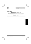
1
USER MANUAL PROFIBUS-DP OPTION OPC-G11S-PDP for Fuji FRENIC5000G11S/P11S & GE Fuji AF-300G11/P11 DOC. NO. SDM-7526-011 HMS FIELDBUS SYSTEMS AB PILEFELTSGATAN 93 - 95 S - 302 50 HALMSTAD SWEDEN PHONE: +46 35 17 29 00 FAX: +46 35 17 29 09 e-mail: [email protected] web: www.hms.se ® USER MANUAL Revision 0.14 2000-01-14 Revision Notes Date: Document: Document: Notes: 99.10.22 Revision 0.10 Created by Anders Arvidsson 99.10.28 Revision 0.11 Minor changes due to remarks from Karin Johansson 99.11.15 Revision 0.12 Compilation and changes according to Fuji remarks 99.12.20 Revision 0.13 Changes according to Fuji GE remarks 00.01.10 Revision 0.14 Minor spelling changes Preface The data and illustrations found in this document are not binding. We reserve the right to modify our products in line with our policy of continuous product development. The information in this appendix is subject to change without notice and should not be considered as a commitment by HMS FIELDBUS SYSTEMS AB. HMS FIELDBUS SYSTEMS AB assumes no responsibility for any errors that may appear in this document. The product and technology described in this document is patent pending in the following countries: USA, Canada, Japan, Belgium, Denmark, Finland, France, Greece, Ireland, Italy, Luxemburg, Monaco, Netherlands, Portugal, Switzerland, Lichtenstein, Spain, United Kingdom, Sweden, Germany and Austria. ANYBUS is a registered trademark of HMS FIELDBUS SYSTEMS AB. All other trademarks are the property of their respective holders. Related documents Document Author PROFIBUS Profile for variable speed drives, PROFIDRIVE. PNO Order-No 3.072 PROFIDRIVE working group of Profibus Nutzerorganisation FRENIC5000G11S/P11S INSTRUCTION MANUAL, INR-Si47-0554-E Fuji Electric HMS FIELDBUS SYSTEMS AB 2 USER MANUAL Revision 0.14 2000-01-14 Table of Contents 1. Applicable inverters......................................................5 2. Receiving Inspection.....................................................6 3. Installation ....................................................................7 3.1 Installation Method ..................................................................................................................................... 7 3.2 Installation Checklist ................................................................................................................................... 8 4. Profibus option card OPC-G11S-PDP.............................9 5. Introduction to Profibus-DP .........................................9 5.1 Technical features of Profibus-DP................................................................................................................ 9 6. OPC-G11S-PDP Overview .............................................11 6.1 Physical interface........................................................................................................................................ 11 6.2 Configuration............................................................................................................................................. 12 6.2.1 Baudrate ............................................................................................................................................. 12 6.2.2 Termination ....................................................................................................................................... 12 6.2.3 Node Address..................................................................................................................................... 12 6.2.4 PPO-type selection............................................................................................................................. 14 6.2.5 Changeover of communications .......................................................................................................... 15 6.2.6 Fast stop............................................................................................................................................. 16 6.2.7 Configuration of PCD word 1-4......................................................................................................... 17 6.3 Action at communication error................................................................................................................... 18 6.4 Indication LED’s ....................................................................................................................................... 21 7. Operating the drive via Profidrive profile.................22 7.1 PPO- description ....................................................................................................................................... 22 7.2 PCD-part................................................................................................................................................... 23 7.2.1 Control- / status word ........................................................................................................................ 23 7.2.2 Frequency setpoint/ Actual frequency.................................................................................................. 28 7.2.3 PCD word 1-4 ................................................................................................................................... 28 7.3 PCV-part................................................................................................................................................... 28 7.4 Example..................................................................................................................................................... 33 7.5 Profidrive specific parameters ..................................................................................................................... 34 7.6 Malfunction codes...................................................................................................................................... 36 8. Parameters specific for communication ....................38 8.1 Command data .......................................................................................................................................... 38 8.2 Operation command data........................................................................................................................... 38 HMS FIELDBUS SYSTEMS AB 3 USER MANUAL Revision 0.14 2000-01-14 8.3 Function data ............................................................................................................................................. 40 8.4 Monitoring data ......................................................................................................................................... 41 8.5 Parameter data format ................................................................................................................................ 43 8.6 Data format specification............................................................................................................................ 49 9. System configuration .................................................54 10. GSD-file......................................................................57 HMS FIELDBUS SYSTEMS AB 4 USER MANUAL Revision 0.14 2000-01-14 1. Applicable inverters Item Description Inverter type FRENIC5000G11S/P11S (AF-300G11/P11) Compatible Inverter The last two digits of the model number should be B1 or later Model number Example: 6KG1123X1B1 (GE Fuji version) Minimum inverter ROM version number up to 22 kW(30HP) EN version S08000 and after (It is impossible to use version prior to S08000 inverter.) Japanese standard, JE Cannot be used and CN version UX and GE Fuji version S08000 and after (It is impossible to use version prior to S08200 inverter.) 30 kW(40HP) and EN, Japanese standard, H07602 and after above JN, JE, AN, CN, UX (It is impossible to use versions of H00000 to H07601.) and GE Fuji version NOTE: This product can only be used for Inverters with ROM version numbers greater than or equal to the versions shown above. And in the case of installing this option in the G11/P11 inverter that is a Japanese standard, JN, JE or CN version, please contact Fuji Electric or its distributors. Check the ROM number of your Inverter as follows using the inverter keypad. a. Check that the Inverter Operation monitor (Operation mode) screen is displayed. b. Press the [PRG] key of the Inverter once. c. Select the "5. MAINTENANC" with the cursor and press the [FUNC/DATA] key. d. Press the down cursor key to increment the display at the MAINTENANC screen. Finally, the ROM number is shown in the maintenance information, as indicated by the display "INV=Hxxxxx or Sxxxxx". The maintenance and inspection items are similar to the Inverter unit, for detail refer to the Inverter Instruction Manual. HMS FIELDBUS SYSTEMS AB 5 USER MANUAL Revision 0.14 2000-01-14 2. Receiving Inspection Confirm the following items upon a receipt. 1) The model number matches your purchase order? Check the model number printed on the circuit board. Model : OPC - G11S - PDP OPTION TYPE PDP -> Profibus-DP INTERFACE OPTION INVERTER TYPE G11S -> FRENIC5000G11S/P11S SERIES & AF-300 G11/P11 SERIES Inspection for damage during transportation. Report damage to transportation carrier. HMS FIELDBUS SYSTEMS AB 6 USER MANUAL Revision 0.14 2000-01-14 3. Installation 3.1 Installation Method Please follow the installation procedure described as follows. Please install or detach the option after turning off the input power supply of the inverter and confirming the charge lamp (CHARGE or CRG) is gone out. The shape, the dimensions and the position of the charge lamp of the inverter are different by each capacity. keypad keypad Option unit Top cover Inverter unit Inverter unit PE Line Charge lamp Step1 Step2 to 4 Step1 Loosen two screws(M4) at a and remove the top cover. Loosen two screws(M3) at b and detach the keypad panel. (For the 30kW[40HP] and above inverters, the keypad panel can be detached if the front cover is removed and the screws loosened at b .) Step2 Reassemble the top cover, push-in the option unit and secure it with two screws(M3) at c . Step3 Secure the keypad panel to the option unit with two screws at b . Step4 Connect the ground cable to the PE terminal of the option unit. HMS FIELDBUS SYSTEMS AB 7 USER MANUAL Revision 0.14 2000-01-14 3.2 Installation Checklist After installation and wiring, check the following items. [1] The wiring is correct. [2] No loose wires or screws remain inside the Inverter. [3] The screws and terminals are all tight. [4] There are no loose threads of wires at terminals that may contact other terminals. [5] The switch positions on the Anybus-S module, JP6 on the conversion-board are suitable for the use purpose. (Do not change the JP4 on the conversion-board !) [6] Inverter parameters such as H30, E15, E30 to E32, o27, o28, o30 to o38, are set correctly. (H30: Link Active/Inactive, E15: effect to OFF3, E30: effect to Bit 8 of Status word, E31 and E32: effect to Bit 10 of Status word, o27 and o28: for RAS, o30: PPO type, o31 to o38: PCD setting) HMS FIELDBUS SYSTEMS AB 8 USER MANUAL Revision 0.14 2000-01-14 4. Profibus option card OPC-G11S-PDP The OPC-G11S-PDP option card gives an instant connection between Fuji G11S drives (GE Fuji AF-300G11) and Profibus-DP. The option board will perform as an integrated part of the G11S drive and gives the user access to all relevant parameters, as well as control-/status signals needed to control the drive The OPC-G11S-PDP option card communicates according to the Profibus Protocol Standard DIN 19245 part 1 & 3. This means that it can communicate with all masters that comply with this standard, but it does not necessarily mean that all services available in the profibus standard are supported. The VDI/VDE 3689 Profibus Profile for Variable Speed Drives, also known as Profidrive, is a subset of Profibus which only supports the services relevant to speed control applications. In a control system the OPC-G11S-PDP will act as a slave that can be read and written to, from a Profibus-DP master. It will not initiate communication to other nodes, it will only respond to incoming telegrams. 5. Introduction to Profibus-DP Profibus has an international user organisation called Profibus International, PI, and local national organisations, PNO. HMS is represented as board member of Profibus Sweden since the start of the organisation in 1992 and also as member of the Technical Committee at the American Profibus Trade Organization, PTO. Technical questions regarding the fieldbus should be addressed to your local Profibus User Group in the first instance. Address list is available on the Profibus Internet site; www.Profibus.com. For general help on Profibus, contact Profibus International on e-mail; [email protected]. Profibus-DP is normally used in industrial automation, to transfer fast data for motor controllers, MMI, I/O units and other industrial equipment. 5.1 Technical features of Profibus-DP • Physical media: EIA RS 485 twisted pair cable or fiber optic. • Baud rate: 9.6 kbaud up to 12Mbaud. • Maximum number of nodes: 126 • Maximum number of I/O: 244 bytes/slave. • Bus topology: Master-Slave communication. The figure below gives an overview of a Profibus-DP network. • Cyclic user data transfer between DP-Master and DP-Slaves. • Watch-Dog Timer at the DP-Slaves • Connecting or disconnecting stations without affecting other stations. • Powerful diagnosis mechanisms, 3 hierarchical levels of the diagnosis messages. • Synchronization of inputs and/or outputs. • All messages are transmitted with Hamming Distance HD=4. HMS FIELDBUS SYSTEMS AB 9 USER MANUAL Revision 0.14 2000-01-14 PROFIBUS DP Personal Computer with Configuration Software RS-232 Master DP Profibus DP Slave node #1 Profibus DP Slave node #n Profibus DP Slave node #2 Figure 1 Bus topology of ProfibusProfibus- DP Figure 2 Bus cycle time of a ProfibusProfibus - DP Mono Master system(2 bytes I/O data/slave) HMS FIELDBUS SYSTEMS AB 10 USER MANUAL Revision 0.14 2000-01-14 . 6. OPC-G11S-PDP Overview This section contains all necessary information to start-up and configure the OPC-G11S-PDP. 6.1 Physical interface Isolation: The bus is galvanically separated from the other electronics with an on board DC/DC converter. Bus signals (A-line and B-line) are isolated via opto couplers. Profibus-DP communication ASIC: SPC3 chip from Siemens. Bus connection: The OPC-G11S-PDP connects to the profibus network with a 9-pin female DSUB connector. For the pin layout, refer to Table 1. Pin Name Function Housing Shield Connected to PE 1 Not Connected - 2 Not Connected - 3 B-Line Positive RxD/TxD according to RS 485 specification 4 RTS Request To Send * 5 GND BUS Isolated GND from RS 485 side * 6 +5V BUS Isolated +5V from RS 485 side * 7 Not Connected - 8 A-Line Negative RxD/TxD according to RS 485 specification 9 Not Connected - Table 1 Pin Layout • +5V BUS and GND BUS are used for bus termination. Some devices, like optical transceivers (RS485 to fibre optics) might require external power supply from these pins. RTS is used in some equipment to determine the direction of transmission. In standard applications only A-Line, B-Line and Shield are used. HMS FIELDBUS SYSTEMS AB 11 USER MANUAL Revision 0.14 2000-01-14 6.2 Configuration 6.2.1 Baudrate The baudrate on a Profibus-DP network is set during configuration of the master and only one baudrate is possible in a Profibus-DP installation. The OPC-G11S-PDP has an auto baudrate detection function and the user does not have to configure the baudrate on the module. Refer to Table 2 for the baudrates supported. Baudrates supported by OPCG11S-PDP 9.6 kbit/s 19.2 kbit/s 93.75 kbit/s 187.5 kbit/s 500 kbit/s 1.5 Mbit/s 3 Mbit/s 6 Mbit/s 12 Mbit/s Table 2 Supported baudrates 6.2.2 Termination The end nodes in a Profibus-DP network has to be terminated to avoid reflections on the bus line. The OPC-G11SPDP is equipped with a termination switch to accomplish this in an easy way. If the module is used as the first or last module in a network the termination switch has to be in ON position. Otherwise the switch has to be in OFF position. Please Note: Note If an external termination connector is used the switch must be in OFF position. Termination switch ON Bus termination enabled If the module is the last or first module, the bus termination has to be set on, or an external termination connector has to be used Termination switch OFF Bus termination disabled 6.2.3 Node Address Before power-on the OPC-G11S-PDP the node address has to be set. This is done with two rotary switches on the module, this enables address settings from 1-99 in decimal format. Looking at the front of the module, the leftmost switch is used for the ten setting and the rightmost switch is used for the setting of the integers. Example: Address = (Left Switch Setting x 10) + (Right Switch Setting x 1) HMS FIELDBUS SYSTEMS AB 12 USER MANUAL Revision 0.14 2000-01-14 Please Note: Note: The node address can not be changed during operation. HMS FIELDBUS SYSTEMS AB 13 USER MANUAL Revision 0.14 2000-01-14 6.2.4 PPO-type selection OPC-G11S-PDP supports PPO-type 1-4. (Refer to chapter 7.1 for PPO description) The same PPO type must be set from both the keypad and the master configuration. If the settings do not comply, the OPC-G11S-PDP will not start exchanging data with the master. Setting the PPO type from keypad: The inverter o-type parameters are used to configure the Profibus-DP interface. The o-type parameters are only accessible from the inverter keypad after the Profibus interface has been installed. PPO type selection is made in parameter o30. After changing this parameter, the drive has to be re-powered for the change to take affect. o30 data PPO type selection 0, 1, 6-255 PPO 1 2 PPO 2 3 PPO 3 4 PPO 4 5 PPO 2 Table 3 PPO type selection Setting the PPO type from master: Identification bytes are transmitted in the configuration frame of the Profibus -DP master. These bytes define the PPO type of the user data frame. The identification bytes are included in the GSD-file (refer to chapter 8) that is used during configuration of the master. For how to configure the Profibus-DP master, please refer to the manual for the actual master. HMS FIELDBUS SYSTEMS AB 14 USER MANUAL Revision 0.14 2000-01-14 6.2.5 Changeover of communications In order to enable the inverter control through the communication (by command data and operation data), the inverter function code "H30: Serial link (Function selection)” should be configured for a value of 1-3. The reading and writing of function data and functions are possible at any time regardless of the setting of Function code H30. Communication Host Frequency command Valid SW1 Frequency command Invalid Forward command H30: Serial linlk Switching circuit of communication valid/invalid Frequency command Frequency setting Forward command Valid Forward command Changeover of communication valid/invalid SW2 Forward command Invalid E 0 1 - E 0 9 : Multi-function term inals setting Changeover signal of communication valid/invalid 6.2.5.1 Changeover method for communication control The changeover of the communication control can be performed by the multi-function command terminals (terminals X1-X9) on the inverter. However, it is necessary to configure the inverter’s multi-function command input terminals (E01 – E09: X1–X9 terminals function) to the link operation selection (Data 24). If the multi-function command terminals have not been set to the link operation selection, the communication becomes valid automatically. Input terminals State OFF Communication invalid mode ON Communication valid mode (H30 setting) Note: 1) Since all memories are initialized at switching power supply on, the command data and operation data must be write again from the upstream units. 2) Even when the communication is invalid, the writing of command data and operation data is valid, but it is not reflected by SW1 • SW2. The changeover without shock is possible by the way the data is set prior to the transition. HMS FIELDBUS SYSTEMS AB 15 USER MANUAL Revision 0.14 2000-01-14 6.2.5.2 Link function configuration (operation selection) The setting (valid/invalid) for command data and operation data during the communication valid period is possible individually by the setting of " H30: Serial link (Function selection)". (By making the communication always valid without setting at the multi-function terminals, changeover for the H30 data valid/invalid can change over the communication valid/invalid, similar to the changeover with multi-function command terminals.) Link function H30 During communication is valid SW1 (Command data) SW2 (Operation data) 0 Invalid Invalid 1 Valid Invalid 2 Invalid Valid 3 Valid Valid During communication is invalid SW1, SW2 Invalid 6.2.5.3 Coexistence of link (option) and RS485 (or Modbus RTU) communication When the link options (such as T link, field bus, etc.) are mounted on the inverter, the communication is positioned as described below and the functions are restricted. Link: The operation through the fieldbus (either one of command data and operation data or both), the operation monitoring, and the reading and changing of functions are possible. RS485: The operation monitoring and the reading and changing of inverter configuration functions codes is possible (Operation through the RS485 communication is impossible). Note: 1) The communication valid bit of M14: Operating state becomes the state signal of link option and not of RS485. 2) When the command data and operation data are accessed from RS485, NAK is returned. 3) If the writing of functions is performed through this communication during the writing of functions by the link, NAK (no writing right error) is returned. 6.2.6 Fast stop When the drive is fast stopped, bit 2 (OFF3 command) in the Control Word, the ramp time specified in Dec time 4 (parameter E15) is used. Refer to chapter 7.2.1 for detailed information about the Control Word. HMS FIELDBUS SYSTEMS AB 16 USER MANUAL Revision 0.14 2000-01-14 6.2.7 Configuration of PCD word 1-4 Assigning parameters to PCD word 1-4 (refer to chapter 7.2.3) can be performed in two ways: 1. From keypad (o31-o38) 2. From network (PNU 915,916) After changing these parameters the drive has to be re-powered for the change to take affect. Assignment from keypad Assignment of PCD write word 1-4 (PLC -> Drive): o31 = Communication number for parameter transferred in PCD1 o32 = Communication number for parameter transferred in PCD2 o33 = Communication number for parameter transferred in PCD3 o34 = Communication number for parameter transferred in PCD4 Assignment of PCD read word 1-4 (Drive ->PLC): o35 = Communication number for parameter transferred in PCD1 o36 = Communication number for parameter transferred in PCD2 o37 = Communication number for parameter transferred in PCD3 o38 = Communication number for parameter transferred in PCD4 Assignment from profibus network Assignment of PCD write word 1-4 (PLC -> Drive) with parameter 915: 915, index 1 = Communication number for parameter transferred in PCD1 915, index 2 = Communication number for parameter transferred in PCD2 915, index 3 = Communication number for parameter transferred in PCD3 915, index 4 = Communication number for parameter transferred in PCD4 Assignment of PCD read word 1-4 (Drive ->PLC) with parameter 916. 916, index 1 = Communication number for parameter transferred in PCD1 916, index 2 = Communication number for parameter transferred in PCD2 916, index 3 = Communication number for parameter transferred in PCD3 916, index 4 = Communication number for parameter transferred in PCD4 Please Note: 1. PCD words 1-4 are only enabled if PPO 2 or 4 is selected. 2. Communication numbers are within the range 1-255. See Section 8.5 for an index of inverter communication numbers. If a communication number is set to 0, the actual PCD word will be ignored. HMS FIELDBUS SYSTEMS AB 17 USER MANUAL Revision 0.14 2000-01-14 6.3 Action at communication error In case of occurring transmission errors (communication cutoff with the master), the following actions can be selected. 1) Select action when error is detected. (o27) o27 Action at error detection Remarks 0 Immediate forced stop Er5 1 Continue operation within o28 time and stop Er5 2 Continue operation according to the last command received until restoration of the communication. If the communication is not restored before the o28 time expires, then immediate forced stop. Er5 3 Continue operation till restoration of the communication, and after the restoration, follow to designation of communication. Automatic restoration after restoring communication Continue operation using the command just before the error within o28 time, but when restoring, operate following to the designation of communication. 2) Setting time of timer at error (o28) 0.0 – 60.0s In a case of o27=0 (Mode of immediate forced stop at communication error detection) Communication state Display Error Normal Normal Alarm reset Normal Er 5 Communication failure FWD Command from Master ON ON Setting frequency Operation command Internal operation of inverter Operation Stop Operation Setting frequency Output frequency HMS FIELDBUS SYSTEMS AB Coast-to-stop 18 USER MANUAL Revision 0.14 2000-01-14 In a case of o27=1, o28=5.0 s (Mode of immediate forced stop after 5 s at occurring communication error) Communication state Error Normal Alarm reset Normal Normal Er 5 Display 5.0s *1 FWD Command from Master OFF ON Setting frequency Operation command Internal operation of inverter ON Operation Stop Operation Setting frequency Output frequency Coast-to-stop In acceleration, even if occurring transmission error,accelerated to the setting frequency. *1) In a period until restoring the communication, the last commands (command data and operation data) received before the error are kept. In a case of o27=2, o28=5.0 s (The communication is not restored for 5.0 sec after error detection, and inverter trips Er5.) Communication state Error Normal Alarm reset Normal Normal Display Er 5 5.0s *1 FWD Command from Master ON ON Setting frequency Operation command Internal operation of inverter Operation Stop Operation Setting frequency Output frequency Coast-to-stop In acceleration, even if occurring transmission error, accelerated to the setting frequency. HMS FIELDBUS SYSTEMS AB 19 USER MANUAL Revision 0.14 2000-01-14 In a case of o27=2, o28=5.0 s (A communication error occurs, but restored within 5 s.) Communication state Error Normal Normal Normal Display 5.0s *1 FWD Command from Master ON OFF Operation Stop Setting frequency Operation command Internal operation of inverter Setting frequency Output frequency In acceleration, even if occurring error, accelerated to the setting transmission frequency. *1) In a period until restoring the communication, the commands (command data and operation data) just before the error are kept. In a case of o27=3 (When a communication error occurs, the operation continues) Communication state Error Normal Normal Normal Display *1 FWD Command from Master ON ON Setting frequency Operation command Internal operation of inverter Operation Setting frequency Output frequency Continue operation keeping the setting at occurring transmission error HMS FIELDBUS SYSTEMS AB 20 USER MANUAL Revision 0.14 2000-01-14 6.4 Indication LED’s The OPC-G11S-PDP is equipped with four LED’s. The function of the LED’s are described in Figure 3 and Table 4. 1. Not used 2. On-Line 3. Off-Line 4. Fieldbus diagnostics Figure 3 LED's Name Color Function Fieldbus diagnostics Red Flashing Red 1 Hz - Error in configuration: PPO-type set in parameter o30 does not match PPO-type set during configuration of the network. Flashing Red 4 Hz - Error in initialisation of the Profibus communication ASIC. Turned Off - No diagnostics present On-Line Green Indicates that the module is On-Line on the fieldbus. Green - Module is On-Line and data exchange is possible. Turned Off - Module is not On-Line Off-Line Red Indicates that the module is Off-Line on the fieldbus. Red - Module is Off-Line and no data exchange is possible. Turned Off - Module is not Off-Line Table 4 LED functionality HMS FIELDBUS SYSTEMS AB 21 USER MANUAL Revision 0.14 2000-01-14 7. Operating the drive via Profidrive profile This section describes how to control drive via control word/status word and how to access drive parameters. 7.1 PPO- description The structure of the user data is designated as parameter process data objects (PPO) in the Profidrive profile. The profile defines five PPO types, where OPC-G11S-PDP supports PPO1-PPO4. There are PPO’s with a parameter area (PCV) and a process data area (PCD). There is also PPO’s that consist exclusively of process data (PCD). 1. PPO1 consists of the PCV area and 2 words PCD. 2. PPO2 consists of the PCV area and 6 words PCD. 3. PPO3 consists only of 2 words PCD. 4. PPO4 consists only of 6 words PCD. The PPO type is defined in the Profibus-DP master parameter settings and must comply with the setting in parameter o30 (refer to chapter 6.2.4) PCV PCA Word PCD IND PVA CTW MRV PCD PCD PCD PCD PCD PCD PCD PCD STW MAV 1 2 3 4 5 6 7 8 7 8 9 10 7 8 9 10 1 2 3 4 5 6 1 2 3 4 5 6 5 6 5 6 PPO1 Word PPO2 Word PPO3 Word PPO4 Please Note: Note PPO type is selected at power-up and can not be changed in run-time. HMS FIELDBUS SYSTEMS AB 22 USER MANUAL Revision 0.14 2000-01-14 7.2 PCD-part In this chapter the process data part (PCD) of a PPO is discussed. The PCD part consists of a fixed part (all PPO’s) and a parameterable part (only PPO 2 & 4). In the fixed part, control word and speed reference are transferred to the drive while status word and actual output frequency are transferred from the drive. In the parameterable part, PCD word 1-4, the user can configure what parameters that should be transferred to/from the drive every bus-cycle. 7.2.1 Control- / status word This section describes how to operate the drive with the control-/status word. Text written in italic refers to the actual state in the profidrive state diagram (refer to Figure 4). Profidrive Control Word: The control word is used to send control commands to the inverter (PLC->Drive). Bit # of control word Bit = 0 Bit = 1 0 OFF1 (normal stop) ON1 1 OFF2 (coast stop) ON2 2 OFF3 (fast stop) ON3 3 Operation disabled Operation enabled 4 Ramp generator disabled Condition for operation 5 Stop ramp generator Ramp generator enabled 6 Setpoint disabled Setpoint enabled 7 No function Fault acknowledge 8 Not used Not used 9 Not used Not used 10 Data not valid Data valid 11 No function Reversing 12-15 Not used Not used Bit 0, OFF1/ON1: Bit=0: Normal stop that uses deceleration time specified in DEC TIME1 (Enter OFF1 active state). When output frequency = 0 the drive output is disabled. Bit=1: Drive can be started if all other start conditions are fulfilled. Bit 1, OFF2/ON2: Bit=0: Drive coast to stop (Enter OFF2 active state). Returns to Switch-on inhibit state. Bit=1: Drive can be started if all other start conditions are fulfilled. HMS FIELDBUS SYSTEMS AB 23 USER MANUAL Revision 0.14 2000-01-14 Bit 2, OFF3/ON3: Bit=0: Fast stop that uses deceleration time specified in DEC TIME4 (Enter OFF3 active state). When output frequency = 0 the drive output is disabled. Bit=1: Drive can be started if all other start conditions are fulfilled. Bit 3, Operation disabled/enabled Bit=0: Drive coast to stop (Enter Inhibit operation state). Bit=1: Drive can be started if all other start conditions are fulfilled. Bit 4, Ramp generator disabled/ Condition for operation Bit=0: Output frequency is set to 0. Inverter remains in Running state. Bit=1: Drive can be started if all other start conditions are fulfilled. Bit 5, Stop ramp generator/ Ramp generator enabled Bit=0: Actual output frequency is frozen. Changes to frequency setpoint has no affect. Bit=1: Drive can be started if all other start conditions are fulfilled. Bit 6, Setpoint disabled/enabled Bit=0: Normal stop that uses deceleration time specified in DEC TIME1. Bit=1: Drive can be started if all other start conditions are fulfilled. Bit 7, No function/ Fault acknowledge Bit=0: No fault acknowledge. Bit=1: Fault is acknowledged on positive edge, i.e. bit = 0 then 1 (Enter Switch-on inhibit state). Bit 10, Data invalid/ Data valid Bit=0: The control word and frequency setpoint (from PROFIBUS) are not activated. Bit=1: The control word and frequency setpoint (from PROFIBUS) are activated. Bit 11, No function/Reversing Bit=0: Drive is not reversing. Bit=1: Drive is reversing. HMS FIELDBUS SYSTEMS AB 24 USER MANUAL Revision 0.14 2000-01-14 Profidrive Status Word: The status word indicates the status of the inverter (Drive -> PLC). Bit # of status word Bit = 0 Bit = 1 0 Not ready for switch-on Ready to switch-on 1 Not ready for operation Ready for operation 2 Operation inhibited Operation enabled 3 No fault Trip 4 OFF2 ON2 5 OFF3 ON3 6 Start disable Start enable 7 No alarm Alarm 8 Frequency not equal to setpoint Frequency equal to setpoint 9 Local control Bus control 10 Frequency out of range Frequency within range 11-15 Not used Not used Bit 0, Not ready for switch-on / Ready to switch-on Bit=0: Control word bit 0,1 or 2 (OFF1, OFF2, OFF3) is set to 0, or the drive has tripped. Bit=1: Control word bit 0 = 0 and bits 1, 2,10 are set to 1 (Ready to switch-on state). Bit 1, Not ready for operation / Ready for operation Bit=0: Control word bit 0,1 or 2 (OFF1, OFF2, OFF3) is set to 0, or the drive has tripped. Bit=1: Control word bit 0,1 and 2 are set to 1, and the drive has not tripped (Ready state). Bit 2, Operation inhibited / Operation enabled Bit=0: Control word bit 0,1,2 or 3 (OFF1, OFF2, OFF3 or Operation disabled) is set to 0, or the drive has tripped. Bit=1: Control word bit 0,1,2 and 3 are set to 1, and the drive has not tripped (Enable operation state). Bit 3, No Fault/ Fault (Trip) Bit=0: Drive has not tripped. Bit=1: Drive is tripped. Fault reset from keypad or bit 7 in Control Word is needed to reset the drive after the fault is cleared. Bit 4, OFF2/ ON2 Bit=0: OFF2 command active. Control word bit 1 = 0 (OFF2 active state). Bit=1: Control word bit 1 = 1. HMS FIELDBUS SYSTEMS AB 25 USER MANUAL Revision 0.14 2000-01-14 Bit 5, OFF3/ ON3 Bit=0: OFF3 command active. Control word bit 2 = 0 (OFF3 active state). Bit=1: Control word bit 2 = 1. Bit 6, Start disable/ Start enable Bit=0: Control word bit 0 = 0 and bit 10 = 1 (Not Ready to switch-on state). Bit=1: Control word bit 1 or 2 (OFF2, OFF3 ) is set to 0 or fault trip has been acknowledged (Switch-on inhibit). Bit 8, Frequency not equal to setpoint/ Frequency equal to setpoint Bit=0: Actual output frequency does not equal frequency setpoint (i.e. motor is accelerating / decelerating). Bit=1: Actual output frequency does equal frequency setpoint. Please Note: The frequency tolerance width is configured in parameter E30. Bit 9, Local control/ Bus control Bit=0: Run command and Frequency setting are invalid via Profibus. Bit=1: Run command or Frequency setting are valid via Profibus. Bit 10, Frequency out of range/ Frequency within range Bit=0: Actual output frequency is lower than the limit specified in parameter E31 and E32. Bit=1: Actual output frequency is above or equal to the limit specified in parameter E31 and E32 . HMS FIELDBUS SYSTEMS AB 26 USER MANUAL Revision 0.14 2000-01-14 Voltage switched-off Switch-on inhibit Voltage ON A B Bit 6 = 1 From every state OFF1(bit 0 = 0) C Not ready for switch-on D Control word, bit pattern: XXXX X1XX XXXX X110 Inhibit operation (bit3 = 0) Bit 2 = 0 Coast stop Inhibit operation active Ready to switch-on Stop drive Bit 3 = 1 Fault Fault acknowledge: Bit7: 0 to 1 Bit 0 = 1 ON1 (bit 0 = 1) From every state Drive stopped Ready B C D OFF1(bit 0 = 0) Normal stop OFF 1 active stage 1 Bit 1 = 0 Open load contactor Enable operation C A D Stop RFG (bit 5 = 0) D B OFF 3 active stage 1 OFF2(bit 1 = 0) OFF 2 active Coast stop Bit 4 = 0 Drive stopped Bit 2 = 1 Open load contactor RFG output enabled (bit 4 = 1) Ramp function generator: Enabled output Inhibit setpoint (bit 6 = 0) Drive stopped Quick stop Bit 5 = 0 Enable operation (bit 3 = 1) RFG output disabled (bit 4 = 0) From every state OFF3(bit 2 = 0) Bit 1 = 1 Load contactor open OFF 3 active stage 2 Load contactor open RFG Acceleration enabled (bit 5 = 1) Ramp function generator: Acceleration enabled OFF 1 active stage 2 C Load contactor open D Enable setpoint (bit 6 = 1) Operating state Figure 4 Profidrive state diagram HMS FIELDBUS SYSTEMS AB 27 USER MANUAL Revision 0.14 2000-01-14 7.2.2 Frequency setpoint/ Actual frequency The data format is “Standardized value”, where 0 hex = 0 % and 4000 hex is 100% of Max. frequency specified in parameter F03 or A01. Standardized value A linear value. 0%=0 (0h), 100% is 214 (4000h) Data type N2 Range -200%…200%-2-14 Resolution 2-14 = 0.0061% Length 2 bytes Notation: 2’s complement notation. st st MSB is 1 bit after sign bit in 1 byte. Sign bit = 0 = positive number Sign bit = 1 = negative number Bit 8 7 0 6 -1 5 4 -2 3 -3 2 -4 -5 1 Byte 1 SIGN 2 2 2 2 2 2 2-6 Byte 2 2-7 2-8 2-9 2-10 2-11 2-12 2-13 2-14 7.2.3 PCD word 1-4 In PCD word 1-4 the user can determine which drive parameters that should be transferred to/from the drive every bus-cycle. Refer to chapter 6.2.7 for configuration of PCD word 1-4. 7.3 PCV-part The parameter part (PCV) is fixed to 4 words and can be used for reading and/or updating the parameters in the drive one by one. Requests and responses is a handshake procedure and cannot be batched, meaning that if the master sends out a read/write request, it has to wait for the response, before it sends a new request. The PCV is further divided into three parts; PCA- Parameter Characteristics (1 word), IND – Subindex (1 word) and PVA- Parameter value (2 words). PCA handling: b15 b14 b13 b12 RC b11 b10 b9 b8 b7 SPM b6 b5 b4 b3 b2 b1 b0 PNU Figure 5 PCA word RC: Request/response characteristics (Range 0-15) SPM: Toggle bit for Spontaneous Messages, not used by OPC-G11S-PDP. HMS FIELDBUS SYSTEMS AB 28 USER MANUAL Revision 0.14 2000-01-14 PNU: Parameter number. Range 1-255 for G11S specific parameters and 900-999 for profidrive specific parameters. Please refer to chapter 7.5 for which profidrive specific parameters that are supported HMS FIELDBUS SYSTEMS AB 29 USER MANUAL Revision 0.14 2000-01-14 Request/Response handling The RC portion of the PCA word defines the request/response that may be issued. Since all parameters in G11S are “word type” (16 bits), the PVA part will transmit parameter values in bytes 7 and 8. (Byte 5 and 6 are reserved for parameters that are “long word type” (32 bits) ). If the Request/Response contains array elements, the high byte (byte 3) of the IND word will carry the array subindex. RC content Request: Function: 0 No request 1 Request parameter value 2 Change parameter value (word) 3 Change parameter value (long word)* 4 Request description element* 5 Change description element* 6 Request parameter value (array) 7 Change parameter value (array word) 8 Change parameter value (array long word)* 9 Request number of array elements 10-15 Not used Response: Function: 0 No response 1 Transfer parameter value (word) 2 Transfer parameter value (long word)* 3 Transfer description element* 4 Transfer parameter value (array word) 5 Transfer parameter value (array long word)* 6 Request number of array elements 7 Request rejected (including fault number, see below) 8 Not parameter change rights by PCV interface 9-15 Not used If the drive rejects a request from the master, the RC word in the PPO-read will indicate this by assuming value 7. The describing fault number (refer to Table 5) will be found in the PVA part. HMS FIELDBUS SYSTEMS AB 30 USER MANUAL Revision 0.14 2000-01-14 * Not supported by OPC-G11S-PDP HMS FIELDBUS SYSTEMS AB 31 USER MANUAL Revision 0.14 2000-01-14 Fault number Interpretation 0 Non-admissible parameter number 1 Parameter value can not be changed 2 Upper or lower limit exceeded 3 Erroneous sub-index 4 No array 5 Incorrect data type 7 Descriptive element cannot be changed 9 Descriptive data not available 11 No parameter change rights 17 Task can not be executed due to operating status 101 Priority of link error 102 Drive communication error 103 Busy communicating with another unit 104 Error during writing 105 Flash segment overflow 106 Illegal task requested Table 5 Fault number HMS FIELDBUS SYSTEMS AB 32 USER MANUAL Revision 0.14 2000-01-14 7.4 Example In this example, PPO1 is used to set parameter S08 (Acceleration time 1) to 4.0 seconds. Also, a Start command and a frequency setpoint (50%) is given. Request 20 08 00 00 00 00 00 28 04 06/7F* 20 00 Response 10 08 00 00 00 00 00 28 03 37 20 00 In the request message the first two bytes are used for parameter identification. The first digit (2) denotes the function “Change parameter value” (refer to chapter 7.3). The second digit along with the second byte (0 and 08) indicates parameter nr. 8. Bytes 7 and 8 (00 28 = DEC 40) is the parameter value (40 meaning 4.0 seconds). The last four bytes are the Control Word and Frequency setpoint. Control Word value 04 06 -> 04 7F* starts the motor, while 20 00 (refer to 7.2.2) signifies 50 % of the maximum frequency specified in parameter F03 or A01. In the response message, the first digit (1) indicates the function “Transfer parameter value” . The last four bytes are Status Word and Actual frequency (%). *To start the drive the profibus state machine must be shifted in a correct way. This may be done in two steps. First the control word should be set to 04 06 (Enter Ready to switch-on state) and then to 04 7F (Enter Operating state). Refer to the state diagram in Figure 4. HMS FIELDBUS SYSTEMS AB 33 USER MANUAL Revision 0.14 2000-01-14 7.5 Profidrive specific parameters The table below shows which profidrive specific parameters that are supported by OPC-G11S-PDP. PNU(Parameter Number) Description Range 915 Refer to chapter 6.2.7 for how to assign PCD words. 1-255 R/W Refer to chapter 6.2.7 for how to assign PCD words. 1-255 R/W Returns address switch setting. 1-99 R 0 - Parameter edit rights from network not possible. 0, 1 R/W Refer to chapter 7.6 for the malfunction codes. R 0-12 R Indexed assignment of PCD write word 1-4 916 Indexed assignment of PCD read word 1-4 918 Profibus-DP slave address 927 Parameter edit rights 1- Parameter edit rights from network possible 947 Index = 1 Fault memory 0 Indexed Fault memory Index = 2 to 8 Fixed to 0 Index = 9 Fault memory (1st prior) Index = 10 to 16 Fixed to 0 Index = 17 Fault memory (2nd prior) Index = 18 to 24 Fixed to 0 Index = 25 Fault memory (3rd prior) Refer to drive parameter M16-M19. 963 PROFIBUS-DP baud rate Shows the baudrate of the Profibus-DP network. 0 = Baud rate not found 1 = 9.6 Kbaud 2 = 19.2 Kbaud 3 = 45.45 Kbaud 4 = 93.75 Kbaud 5 = 187.5 Kbaud 6 = 500 Kbaud 7 = 1.5 Mbaud 8 = 3.0 Mbaud 9 = 6.0 Mbaud HMS FIELDBUS SYSTEMS AB 34 USER MANUAL Revision 0.14 2000-01-14 10 = 12.0 Mbaud 965 Profile version 967 Control Word 968 Status Word 970 Reset to factory setting Returns the Profidrive profile version used in the OPC-G11S-PDP implementation Shows the latest received control word in hex format R Bit 0-15 R Bit 0-15 R 0,1 R/W Refer to chapter 7.2.1 for detailed information about the control word. Shows the latest status word in hex format Refer to chapter 7.2.1 for detailed information about the status word. Parameter for starting the parameter reset to factory setting. After completion of the factory setting, this parameter is also reset to it’s original value, 1. 0 - Start parameter reset 1- No parameter reset Caution: A reset causes the loss of all parameter changes. Table 6 Profidrive parameters HMS FIELDBUS SYSTEMS AB 35 USER MANUAL Revision 0.14 2000-01-14 7.6 Malfunction codes Inverter code (M16 (M16 M19) Description 0 No alarm - 0000 1 Overcurrent (During acceleration) OC1 2301 2 Overcurrent (During deceleration) OC2 2302 3 Overcurrent (While running at constant speed) OC3 2303 4 Overcurrent (Input) OC 2100 5 Ground fault EF 2330 6 Overvoltage (During acceleration) OU1 3211 7 Overvoltage (During deceleration) OU2 3212 8 Overvoltage (While running at constant speed) OU3 3213 10 Undervoltage LU 3220 11 Input phase lose Lin 3130 12 Power supply frequency abnormal FrE 3140 13 AC Fuse blown ACF 5453 14 DC Fuse blown FUS 5450 16 DC link charge circuit abnormal PbF 5120 17 Overheat of heat sink in inverter OH1 4310 18 External alarm input OH2 9000 19 Overheat of unit internal temp. OH3 4110 20 Overheat of motor OH4 4300 22 Overheat of DB resistance dbH 4210 23 Electronic thermal overload relay (Motor 1) OL1 2211 24 Electronic thermal overload relay (Motor 2) OL2 2212 25 Electronic thermal overload relay (Inverter) OLU 2200 27 Overspeed OS 7310 28 PG error Pg 7301 29 Thermistor circuit disconnection nrb 5000 31 Memory error Er1 5500 32 KEYPAD panel communication error Er2 7520 HMS FIELDBUS SYSTEMS AB Malfunction code (HEX) 36 USER MANUAL Revision 0.14 2000-01-14 33 CPU error Er3 5220 34 Option communication error Er4 7510 35 Option error Er5 7511 36 Operating proc. error Er6 F004 37 Output phase loss error Er7 7200 38 RS485 communication error Er8 B100 39 A/D converter defective Er9 7000 HMS FIELDBUS SYSTEMS AB 37 USER MANUAL Revision 0.14 2000-01-14 8. Parameters specific for communication To operate the inverters or to monitor the state via communication, the following parameters are available for communication in addition to the configuration functions of the inverters. These parameters are a common data format applicable to inverter types on and after G11/P11 series, so that it is possible to access different inverter types by the same program on the host side. 8.1 Command data Code Name Unit S01 Setting frequency (p.u.) - S05 Setting frequency Hz Min. unit Read/write -20000–20000 (Maximum frequency at ±20000) 1 R 0.00–400.00 (P11S: 0.00–120.00) 0.01 Variable range R R: Reading W: Writing Note: 1) The data writing exceeding the setting range is possible, but the actual action will be restricted within the inverter. 2) When the command data is read, it is not the command data of actual action but the command data communicated before (the final command data can be obtained by reading of the monitoring data described later). 8.2 Operation command data Code Name Unit Variable range Min. unit Read/write S06 Operation command - Refer to the data format [11] - R/W S07 Universal Do - Refer to the data format [12] - R/W S12 Universal Ao - -20000–20000 (100% output at ±20000) 1 R/W Note: 1) Since X1–X9 are multi-function inputs, it is necessary to set the functions with E01–E09. 2) The alarm reset is executed, when RST signal changes from ON to OFF even there are no alarming factors. 3) Universal Do is a function utilizing inverter’s Do via transmission. (In detail, refer to the detail descriptions E20–E24 in "Function Explanation" in the instruction manual of inverter). 4) The data writing exceeding the setting range is possible, but the actual action will be restricted within the inverter. HMS FIELDBUS SYSTEMS AB 38 USER MANUAL Revision 0.14 2000-01-14 5) When the operation commands are instructed through the communication, the relation to the inverter terminal commands becomes as follows. Function Classification Symbol Name Name FWD/REV FWD/REV command 0–3 SS1, 2, 4, 8 Multistep freq. selection 4, 5 RT1, RT2 ACC/DEC time selection 6 HLD 3-wire operation stop command 7 BX Coast-to-stop command 8 RST Alarm reset 9 THR Trip command (External fault) 10 JOG Jogging operation 11 Hz2/Hz1 Freq. set. 2 / Freq. set. 1 12 M2/M1 Motor 2 / Motor 1 13 DCBRK DC brake command 14 TL2/TL1 Torque limiter 2 / Torque limiter 1 15, 16 SW50, SW60 Switching operation between line and inverter (50, 60Hz) 17, 18 UP, DOWN UP, DOWN command 19 WE-KP Write enable for KEYPAD 20 Hz/PID PID control cancel 21 IVS Inverse mode changeover (terminals 12 and C1) 22 IL Interlock signal for 52-2 23 Hz/TRQ TRQ control cancel 24 LE Link enable (Bus, RS485) 25 U-DI Universal DI 26 STM Pick up start mode 27 PG/Hz SY-PG enable 28 SYC Synchronization command 29 ZERO Zero speed command 30 STOP1 Forced stop command 31 STOP2 Forced stop command with Deceleration time 4 32 EXITE Pre-exciting command Operation command Multi-function command Command HMS FIELDBUS SYSTEMS AB Transmission Terminal block Valid Invalid Invalid Valid Invalid Valid Invalid Valid Invalid Invalid Valid Valid Invalid Invalid Valid Valid Invalid Invalid Valid Valid Valid Invalid Invalid Valid Valid 39 USER MANUAL Revision 0.14 2000-01-14 8.3 Function data Code Name Uni t Variable range Min. unit Read/Write S08 Acceleration time F07 s 0.1–3600.0 0.1 R/W S09 Deceleration time F08 s 0.1–3600.0 0.1 R/W S10 Torque limit level 1 (Driving ) F40 % 20.00–200.00 1.00 R/W 1.00 R/W (P11S : 20.00–150.00), 999 S11 Torque limit level 2 (Braking ) F41 % 0.00, 20.00–200.00 (P11S : 20.00–150.00), 999 Note: 1) The writing to out of the range is treated as out of range error. 2) The acceleration and deceleration time S08 and S09 are assigned to "F07: Acceleration time‚P" and "F08: Deceleration time 1" respectively. 3) The torque limit level 1 and 2 of S10 and S11 are assigned to "F40: Torque limit 1 (Driving )" and "F41: Torque limit 1 (Braking )" respectively HMS FIELDBUS SYSTEMS AB 40 USER MANUAL Revision 0.14 2000-01-14 8.4 Monitoring data Code Description Uni t Range Read/Write Read/Write 1 R 0.01 R 1 R M01 Setting frequency (Final data) - M05 Setting frequency (Final data) Hz M06 Output frequency 1 - -20000–20000 (Maximum frequency at ±20000) M07 Torque calculation value % -200.00–200.00 0.01 R M08 Torque current % -200.00–200.00 0.01 R M09 Output frequency 1 Hz 0.00–400.00 (P11S:0.00–120.00 ) 0.01 R M10 Input power % 0.00–200.00 0.01 R M11 Output current % 0.00–200.00 (Inverter rating at 100.00) 0.01 R M12 Output voltage V 0.0–600.0 1.0 R M13 Operation command (Final data) - Refer to the data format [14] - R M14 Operating state - Refer to the data format [16] - R M15 Y1-Y5 output terminal data - Refer to the data format [15] - R M16 Fault memory 0 - Refer to the 4.6 Malfunction codes - R M17 Fault memory (1st prior) - M18 Fault memory (2nd prior) - M19 Fault memory (3rd prior) - M20 Operating time h 0–65535 1 R M21 DC link circuit voltage V 0–1000 1 R M23 Type code - Refer to the data format [17] - R M24 Capacity code - Refer to the data format [11] - R M25 ROM version - 0–64999 1 R M26 Transmission error code - Refer to the data format [10] - R M27 Setting frequency at alarming (Final data) - -20000–20000 (Maximum frequency at 20000) 1 R M31 Setting Frequency at alarming (Final data) Hz 0–400.00 (P11S: 0.00–120.00) 0.01 R M32 Output frequency at alarming - -20000–20000 (Maximum frequency at ±20000) 1 R M33 Torque calculation value at alarming % -200.00–200.00 0.01 R M34 Torque current at alarming % -200.00–200.00 0.01 R M35 Output frequency 1 at alarming Hz -400.00–400.00 (P11S: -120.00–120.00) 0.01 R M36 Input power at alarming % 0.00–200.00 0.01 R M37 Output current at alarming % 0.00–200.00 (Inverter rating at 100.00) 0.01 R HMS FIELDBUS SYSTEMS AB -20000–20000 (Maximum frequency at ±20000) Min. unit 0–400.00 (P11S: 0.00–120.00) 41 USER MANUAL Revision 0.14 2000-01-14 M38 Output voltage at alarming V 0.0–600.0 1.0 R M39 Operation command at alarming - Refer to the data format [14] - R M40 Operating state at alarming - Refer to the data format [16] - R M41 Y1-Y5 output terminal data at alarming - Refer to the data format [15] - R M42 Operation time at alarming h 0–65535 1 R M43 DC link circuit voltage at alarming V 0–1000 1 R M44 Inverter internal air temp. at alarming °C 0–120 1 R M45 Cooling fin temp. at alarming °C 0–120 1 R M46 Life of main circuit capacitor % 0.0–100.0 0.1 R M47 Life of printed circuit board capacitor h 0–65535 1 R M48 Life of cooling fan h 0–65535 1 R Note : 1) The output frequency 1 is before slip compensation. 2) The output frequency 1 with speed regulator (using option OPC-G11S-PG) is treated as the synchronous frequency. HMS FIELDBUS SYSTEMS AB 42 USER MANUAL Revision 0.14 2000-01-14 8.5 Parameter data format The data formats for various parameter data of the inverters are defined here. The data shall be prepared according to the following data format specifications. The instruction manual of inverter shall be referred to for the range and unit of data. The communication number is used to access inverter parameters through the fieldbus option and to configure process data exchange. List of parameter data format Name Code CommuCommunication Data Format No. decimal decimal Name Code CommuCommunication Data Format No. decimal (Hex.) (Hex.) - 0 - S01 1(1) Setting frequency (p.u.) - 2(2) - - M32 46(2E) Output frequency at alarming [2] - 3(3) - - M33 47(2F) Torque calculation value at alarming [6] - 4(4) - - M34 48(30) Torque current at alarming [6] S05 5(5) Setting frequency [5] M35 49(31) Output frequency 1 at alarming [5] S06 6(6) Operation command [11] M36 50(32) Input power at alarming [5] S07 7(7) Universal Do [12] M37 51(33) Output current at alarming [5] S08 8(8) Acceleration time [3] M38 52(34) Output voltage at alarming [3] S09 9(9) Deceleration time [3] M39 53(35) Operation command at alarming [11] S10 10(A) Torque limit level 1 [5] *1 M40 54(36) Operating state at alarming [13] S11 11(B) Torque limit level 1 [5] *1 M41 55(37) Y1-Y5 output terminal data at [12] S12 12(C) Universal Ao - 13(D) - - M42 56(38) Operating time at alarming [1] - 14(E) - - M43 57(39) DC link circuit voltage at alarming [1] M01 15(F) Setting frequency (Final data) [2] M44 58(3A) Inverter internal air temp. at [1] - 16(10) - - - 17(11) - - M45 59(3B) Cooling fin temp. at alarming [1] - 18(12) - - M46 60(3C) Life of main circuit capacitor [3] M05 19(13) Setting frequency (Final data) [5] M47 61(3D) Life of printed circuit board capacitor [1] M06 20(14) Output frequency 1 [2] M48 62(3E) Life of cooling fan [1] M07 21(15) Torque calculation value [6] - 63(3F) - - M08 22(16) Torque current [6] - 64(40) - - M09 23(17) Output frequency 1 [5] - 65(41) - - M10 24(18) Input power [5] - 66(42) - - M11 25(19) Output current [5] - 67(43) - - M12 26(1A) Output voltage [3] - 68(44) - - HMS FIELDBUS SYSTEMS AB - M31 45(2D) [2] Setting frequency at alarming [5] (Final data) [2] alarming alarming 43 USER MANUAL Revision 0.14 2000-01-14 M13 27(1B) Operation command (Final data) [11] - 69(45) - M14 28(1C) Operating state [13] F00 70(46) Data protection [1] M15 29(1D) Y1-Y5 output terminal data [12] F01 71(47) Frequency command 1 [1] M16 30(1E) Fault memory 0 [1] F02 72(48) Operation method [1] M17 31(1F) Fault memory (1st prior) [1] F03 73(49) Maximum output frequency 1 [1] M18 32(20) Fault memory (2nd prior) [1] F04 74(4A) Base frequency 1 [1] M19 33(21) Fault memory (3rd prior) [1] F05 75(4B) Rated voltage 1 [1] M20 34(22) Operating time [1] F06 76(4C) Maximum output voltage 1 [1] M21 35(23) DC link circuit voltage [1] F07 77(4D) Acceleration time 1 [10] - 36(24) - - F08 78(4E) Deceleration time 1 [10] M23 37(25) Type code [14] F09 79(4F) Torque boost 1 [3] M24 38(26) Capacity code [9] F10 80(50) Electronics thermal overload relay 1 [1] M25 39(27) ROM version [1] M26 40(28) Transmission error processing [1] (Selection) F11 81(51) code M27 41(29) Setting frequency at alarming - Electronics thermal overload relay 1 [10] (Level) [2] (Final data) - 42(2A) - - - 43(2B) - - - 44(2C) - - F12 82(52) Electronics thermal overload relay 1 [3] F13 83(53) Electronics thermal overload relay [1] (Braking resistor) F14 84(54) Restart after momentary power failure [1] (Selection) *1) 999 is treated as 7FFFH. HMS FIELDBUS SYSTEMS AB 44 USER MANUAL Revision 0.14 2000-01-14 Name Code CommuCommunication Data Format No. decimal Name Code CommuCommunication Data Format No. decimal (Hex.) (Hex.) F15 85(55) Frequency limiter (High) [1] E37 135(87) Overload early warning 2 (level) [10] F16 86(56) Frequency limiter (Low) [1] E40 136(88) Display coefficient A [10] F17 87(57) Gain (for frequency setting signal) [3] E41 137(89) Display coefficient B [10] F18 88(58) Bias frequency [4] E43 138(8A) LED monitor (Display selection) [1] F20 89(59) DC brake (Starting frequency) [3] E44 139(8B) LED monitor (Display at STP mode) [1] F21 90(5A) DC brake (Braking level) [1] E45 140(8C) LCD monitor (Display selection) [1] F22 91(5B) DC brake (Braking time) [3] C01 141(8D) Jump frequency 1 [1] F23 92(5C) Starting frequency [3] C02 142(8E) Jump frequency 2 [1] F24 93(5D) Starting frequency (Holding time) [3] C03 143(8F) Jump frequency 3 [1] F25 94(5E) Stop frequency [3] C04 144(90) Jump frequency (Width) [1] F26 95(5F) Motor sound (Carrier frequency) [1] *1 C05 145(91) Multi-step frequency 1 [5] F27 96(60) Motor sound (Sound tone) [1] C06 146(92) Multi-step frequency 2 [5] F30 97(61) FMA terminal (Voltage adjust) [1] C07 147(93) Multi-step frequency 3 [5] F31 98(62) FMA terminal (Function selection) [1] C08 148(94) Multi-step frequency 4 [5] F33 99(63) FMP terminal (Pulse rate multiplier) [1] C09 149(95) Multi-step frequency 5 [5] F34 100(64) FMP terminal (Voltage adjust) [1] C10 150(96) Multi-step frequency 6 [5] F35 101(65) FMP terminal (Function selection) [1] C11 151(97) Multi-step frequency 7 [5] F36 102(66) 30Ry operation mode [1] C20 152(98) Jogging frequency [5] F40 103(67) Torque limit 1 (Driving) [1] C31 154(9A) Analog input offset (terminal 12) / [4] F41 104(68) Torque limit 1 (Braking) [1] F42 105(69) Torque vector control 1 [1] E01 106(6A) X1 terminal function [1] E02 107(6B) X2 terminal function [1] C33 156(9C) Analog filter [5] E03 108(6C) X3 terminal function [1] P01 157(9D) Motor 1 (Number of poles) [1] E04 109(6D) X4 terminal function [1] P02 158(9E) Motor 1 (Capacity) [5] E05 110(6E) X5 terminal function [1] P03 159(9F) Motor 1 (Rated current) [10] E06 111(6F) X6 terminal function [1] P04 160(A0) Motor 1 (Auto-tuning) [1] E07 112(70) X7 terminal function [1] P05 161(A1) Motor 1 (On-line tuning) [1] E08 113(71) X8 terminal function [1] P06 162(A2) Motor 1 (No-load current) [10] E09 114(72) X9 terminal function [1] P07 163(A3) Motor 1 (%R1) [5] E10 115(73) Acceleration time 2 [10] P08 164(A4) Motor 1 (%X) [5] E11 116(74) Deceleration time 2 [10] P09 165(A5) Motor 1 (Slip compensation control ) [5] E12 117(75) Acceleration time 3 [10] H03 166(A6) Data initializing HMS FIELDBUS SYSTEMS AB Analog input bias (terminal 12) C32 155(9B) Analog input offset (terminal C1) / [4] Analog input gain (terminal 12) [1] *2 45 USER MANUAL Revision 0.14 2000-01-14 E13 118(76) Deceleration time 3 [10] H04 167(A7) Auto-reset (Times) [1] E14 119(77) Acceleration time 4 [10] H05 168(A8) Auto-reset(Reset interval) [1] E15 120(78) Deceleration time 4 [10] H06 169(A9) Fan stop operation [1] E16 121(79) Torque limiter 1 (Driving) [1] H07 170(AA) ACC/DCC pattern (Mode selection) [1] E17 122(7A) Torque limiter 1 (Braking) [1] H08 171(AB) Reverse phase sequence lock [1] E20 123(7B) Y1 terminal function [1] H09 172(AC) Start mode (Pick-up mode) [1] E21 124(7C) Y2 terminal function [1] H10 173(AD) Energy-saving operation [1] E22 125(7D) Y3 terminal function [1] H11 174(AE) Deceleration mode [1] E23 126(7E) Y4 terminal function [1] H12 175(AF) Instantaneous overcurrent limiting [1] E24 127(7F) Y5A, Y5C terminal functions [1] H13 176(B0) Auto-restart (Restart time) [3] E25 128(80) Y5 logical reverse function [1] H14 177(B1) Auto-restart (Frequency fall rate) [5] E30 129(81) Frequency arrival (FAR) [3] H15 178(B2) Auto-restart (Holding DC voltage) [1] H16 179(B3) Auto-restart (Detecting width) E31 130(82) Frequency detection 1 (FDT) [1] (level) E32 131(83) Frequency detection (FDT) [3] (Hysteresis width) E33 132(84) Overload early warning [1] (Mode selection) [3] *3 (OPR command selfhold time) H18 180(B4) Torque control (Mode selection) [1] H19 181(B5) Active drive [1] H20 182(B6) PID control (Mode selection) [1] H21 183(B7) PID control (Feed back signal) [1] H22 184(B8) PID control (P-Gain) [5] E34 133(85) Overload early warning 1 (level) [10] H23 185(B9) PID control (I-time) [3] E35 134(86) Overload early warning (Timer time) [3] H24 186(BA) PID control (D-time) [5] E36 135(87) Frequency detection 2 (FDT) (level) [1] H25 187(BB) PID control (Feedback filter) [3] *1) 0.75 kHz is treated as 0000H *2) The communication might not be able to be continued by writing (data 1). *3) 999 is treated as 03E7H (99.9). *4) It is impossible to execute the Auto-tuning via Profibus-DP. HMS FIELDBUS SYSTEMS AB 46 USER MANUAL Revision 0.14 2000-01-14 Name CommuCode Communication Data Format No. decimal Name CommuCode Communication Data Format No. decimal decimal (Hex.) (Hex.) H26 188(BC) PTC thermistor (Mode selection) [1] o36 235(EB) Bus Configuration Parameter 07 [1] H27 189(BD) PTC thermistor (Level) [5] o37 236(EC) Bus Configuration Parameter 08 [1] H28 190(BE) Droop operation [4] o38 237(ED) Bus Configuration Parameter 09 [1] H30 191(BF) Serial link (Function selection) [1] o39 238(EE) Bus Configuration Parameter 10 [1] H31 192(C0) RS485 (Address) [1] *1 o40 239(EF) Bus Configuration Parameter 11 [1] H32 193(C1) RS485 (Mode selection on error) [1] *1 o41/ 240(F0) Bus Configuration Parameter 12/ [1] / H33 194(C2) RS485 (Timer time) [3] *1 H34 195(C3) RS485 (Baud rate) [1] *1 o42/ H35 196(C4) RS485 (Data length) [1] *1 H36 197(C5) RS485 (Parity check) [1] *1 o43/ H37 198(C6) RS485 (Stop bits) [1] *1 H38 199(C7) RS485 (No response detection time) [1] *1 o44/ H39 200(C8) RS485 (Response interval) [5] *1 A01 201(C9) Maximum frequency 2 [1] o45/ A02 202(CA) Base frequency 2 [1] (o13) A03 203(CB) Rated voltage 2 (at base speed) [1] o46/ A04 204(CC) Maximum output voltage 2 [1] (o14) A05 205(CD) Torque boost 2 [3] o47/ 246(F6) Bus Configuration Parameter 18/ [1] / A06 206(CE) Electronics thermal 2 (Selection) [1] (o15) Z phase matching gain [3] A07 207(CF) Electronics thermal 2 (Level) [10] o48/ 247(F7) Bus Configuration Parameter 19/ [1] / A08 208(D0) Electronics thermal 2 [3] (o16) (Thermal time constant) (o09) (o10) (o11) (o12) o49/ 241(F1) Bus Configuration Parameter 13/ Time constant of pulse train input filter 242(F2) Bus Configuration Parameter 14/ Command pulse compensation coefficient 1 243(F3) Bus Configuration Parameter 15/ Command pulse compensation coefficient 2 244(F4) Bus Configuration Parameter 16/ Main speed regulator gain 245(F5) Bus Configuration Parameter 17/ APR P gain Offset angle 248(F8) Bus Configuration Parameter 20/ Detecting angle width for completion [1] [1] / [7] [1] / [1] [1] / [1] [1] / [3] [1] / [5] [1] [1] / A09 209(D1) Torque vector control 2 [1] A10 210(D2) Motor 2 (Number of motor-2 poles) [1] A11 211(D3) Motor 2 (Capacity) [5] o50/ A12 212(D4) Motor 2 (Rated current) [10] (o18) A13 213(D5) Motor 2 (Auto-tuning) [1] o51 250(FA) Bus Configuration Parameter 22/ [1] A14 214(D6) Motor 2 (On-line tuning) [1] o52 251(FB) Bus Configuration Parameter 23/ [1] A15 215(D7) Motor 2 (No load current [10] o53 252(FC) Bus Configuration Parameter 24/ [1] A16 216(D8) Motor 2 (%R1 setting) [5] o54 253(FD) Bus Configuration Parameter 25/ [1] A17 217(D9) Motor 2 (%X setting) [5] o55 254(FE) Bus Configuration Parameter 26/ [1] A18 218(DA) Motor 2 (Slip compensation control 2) [5] - 255(FF) - HMS FIELDBUS SYSTEMS AB (o17) Base side number of encoder pulses [1] of synchronizing 249(F9) Bus Configuration Parameter 21/ Too mach deviation [1] / [1] - 47 USER MANUAL Revision 0.14 2000-01-14 o01 219(DB) Speed command system / [15] automatic speed control system o02 220(DC) Time constant of PG vector and [7] speed command filter o03 221(DD) Number of feedback PG pulses [1] o04 222(DE) Constant P of feedback speed [5] controller o05 223(DF) Constant I of feedback speed [7] controller o06 224(E0) Time constant of feedback [7] speed detection filter o07 225(E1) Feedback pulse correction [1] coefficient 1 o08 226(E2) Feedback pulse correction [1] coefficient 2 o27 227(E3) Mode selection on error [1] o28 228(E4) Timer time setting [3] o30 229(E5) Bus Configuration Parameter 01 [1] o31 230(E6) Bus Configuration Parameter 02 [1] o32 231(E7) Bus Configuration Parameter 03 [1] o33 232(E8) Bus Configuration Parameter 04 [1] o34 233(E9) Bus Configuration Parameter 05 [1] o35 234(EA) Bus Configuration Parameter 06 [1] *1) Read-only from communication. *2) It is impossible to execute the Auto-tuning via Profibus-DP. HMS FIELDBUS SYSTEMS AB 48 USER MANUAL Revision 0.14 2000-01-14 8.6 Data format specification All data within the data field of the communication frame consist of 16 bits binary data. (MSB) 15 (LSB) 14 13 12 11 10 9 8 7 6 5 4 3 2 1 0 16-bits binary data (Negative data is treated with two’s complement.) Data format [1] Integer data (Positive): Min. unit 1 Example) If F15 (Frequency limiter, high limit) = 60 Hz, 60 * 1 = 60 = 003CH -> 0 0 3 C -> F F E C -> 0 3 E 8 -> F F C E -> 1 3 A 1 -> D E A 6 -> 0 6 9 Data format [2] Integer data (Positive, negative): Min. unit 1 Example) If F18 (Bias frequency) = -20 Hz, -20 * 1 = -20 = FFECH(two’s complement) Data format [3] Decimal data (Positive): Min. unit 0.1 Example) If F17 Gain (for frequency setting signal) = 100.0%, 100.0 * 10 = 1000 = 03E8H Data Data format [4] Decimal data (Positive, negative): Min. unit 0.1 Example) If H28 (Droop operation) = -5.0Hz, -5.0 * 10 = -50 = FFCEH(two’s complement) Data format [5] Decimal data (Positive): Min. unit 0.01 Example) If C05 (Multi-step frequency 1) = 50.25 Hz, 50.25 * 100 = 5025 = 13A1H Data format [6] Decimal data (Positive, negative): Min. unit 0.01 Example) If M07 (Actual torque value) = -85.38%, -85.38 * 100 = -8538 = DEA6H(two’s complement) Data format [7] Decimal data (Positive): Min. unit 0.001 Example) If o05 (Constant I of feedback speed controller) = 0.105s, 0.105 * 1000 = 105 = 0069H HMS FIELDBUS SYSTEMS AB 0 49 USER MANUAL Revision 0.14 2000-01-14 Data format [8] Decimal data (Positive, negative): Min. unit 0.001 Example) If being -1.234, -1.234 * 1000 = -1234 = FB2EH(two’s complement) F -> B 2 E Data format [9]• [9] Capacity code Code Capacity (kW) Code Capacity (kW) Code Capacity (kW) 5 0.05 1100 11 11000 110 10 0.1 1500 15 13200 132 20 0.2 1850 18.5 16000 160 40 0.4 2200 22 20000 200 75 0.75 3000 30 22000 220 150 1.5 3700 37 25000 250 220 2.2 4500 45 28000 280 370 3.7 5500 55 31500 315 550 5.5 7500 75 35500 355 750 7.5 9000 90 40000 400 Example) If 30kW Since 30 * 100 = 3000 = 0BB8H 0 -> B B 8 Data format [10] Exponential data (ACC/DEC time, current value, display coefficient) (MSB) (LSB) 15 14 13 12 Polarity 0 0 0 11 10 9 8 7 Index potion 6 5 4 3 2 1 0 Data portion Not used 0: 0.01 * 001–999 (0.00 – 9.99) 1: 0.1 * 100–999 (10.0 – 99.9) 2: 1 * 100–999 (100 – 999) 3: 10 * 100–999 (1000 – 3600) 0: Positive (+), 1:Negative (-) Example) F07 (Acceleration time 1) = 20.0 s, 20.0 = 0.1 * 200 HMS FIELDBUS SYSTEMS AB -> 0 4 C 8 50 USER MANUAL Revision 0.14 2000-01-14 Data format [11] Operation command 12 11 10 9 8 7 6 5 4 3 2 0 0 0 0 X9 X8 X7 X6 X5 X4 X3 X2 X1 Alarm reset command Not used Multi-function command 1 0 FWD 13 REV 14 (RST) 15 FWD: Forward rotation command REV: Reverse rotation command (All bits are ON by 1) Example) If M13 (Operation command, Final command) = FWD, X1, X5 = ON, 0000 0000 0100 0101b = 0045H 0 -> 0 4 5 Data format [12] Universal output terminal 15 14 13 12 11 10 9 8 7 6 5 4 3 2 1 0 0 0 0 0 0 0 0 0 0 0 0 Y5 Y4 Y3 Y2 Y1 Not used Universal command (All bits are ON by 1) Example) If M15 (Universal output terminal) = Y1, Y5 = ON, 0000 0000 0001 0001b.= 0011H HMS FIELDBUS SYSTEMS AB -> 0 0 1 1 51 USER MANUAL Revision 0.14 2000-01-14 Data format [13] Operating status 15 14 - 13 WR 12 11 10 9 RL ALM DEC ACC 8 7 6 5 IL VL TL 4 3 2 1 0 NUV BRK INT EXT REV FWD (All bit are ON or active by 1) FWD: In forward operation IL: In current limiting REV: In reverse operation ACC: In acceleration EXT: In DC braking (or in pre-excitation) DEC: In deceleration ALM: Alarm INT: Inverter trip RL: Transmission valid BRK: In braking WR: Function writing right NUV: DC link voltage is establishment (Undervoltage condition at 0) 0: Keypad panel 1: RS485 TL: In torque limiting VL: In voltage limiting 2: Link (option) Example) Omitted (Monitoring method is similar as in the formats [11] and [12].) Data format [14] Type code 15 14 13 12 11 10 Unit type Code 9 8 7 6 Generation Type 5 4 3 Series Generation 2 1 Voltage series Series Voltage series 1 VG 11th series For Japan 100V single phase 2 G - For Asia 200V single phase 3 P - For China 200V three phase 4 E - For Europe 400V three phase 5 C - For USA 575V three phase 6 S - - - HMS FIELDBUS SYSTEMS AB 0 52 USER MANUAL Revision 0.14 2000-01-14 Data format [15] Code setting setting (1 – 4 figures) 15 14 13 Data 4 12 11 10 9 Data 3 8 7 6 5 4 3 2 Data 2 1 0 Data 1 Example) If "o22:Ai function selection" = 123, Since 123 = 0123H HMS FIELDBUS SYSTEMS AB ⇒ 0 1 2 3 53 USER MANUAL Revision 0.14 2000-01-14 9. System configuration This is an example how to configure the OPC-G11S-PDP in the Siemens step 7 program. Start up the HW configure part and install the GSD file for the OPC-G11S-PDP. This is done under Options/ Install New DDB files. Choose the GSD file HMS_1011 and press open. HMS FIELDBUS SYSTEMS AB 54 USER MANUAL Revision 0.14 2000-01-14 Then start up a new project and configure the PLC and Profibus master. Set-up the Profibus master with baud rate and parameters. Create a network for the Profibus system by choosing insert/ DP Master System. Click on OPC-G11S-PDP in the Hardware catalogue (Profibus DP/Additional Field Devices/ Antriebe )and drag the folder to the Profibus network line. Then choose the PPO type and press OK. HMS FIELDBUS SYSTEMS AB 55 USER MANUAL Revision 0.14 2000-01-14 The configuration program will now automatically set-up the module with IN and OUT addresses. To see how the module is configured or to change addresses double click on Universal Module. When the module is configured the configuration can be downloaded to the master, this is done under PLC/Download. HMS FIELDBUS SYSTEMS AB 56 USER MANUAL Revision 0.14 2000-01-14 10. GSD-file Each device on a Profibus-DP network is associated with a GSD file, containing all necessary information about the device. This text file is used by the network configuration program during configuration of the network. The GSD-file for OPC-G11S-PDP(HMS_1011.GSD) is shown below. ;============================================================ ; Profibus Device Database of : HMS Fieldbus Systems DP-slave ; Model : OPC-G11S-PDP ; Description : Profidrive Profibus-DP option board for FUJI G11-inverter ; Language : English ; Date : 20 October 1999 ; Author : HMS Fieldbus Systems AB ;============================================================ #Profibus_DP GSD_Revision =1 ; Device identification Vendor_Name = "HMS Fieldbus Systems AB" Model_Name = "OPC-G11S-PDP" Revision = "Version 1.00" Ident_Number = 0x1011 Protocol_Ident =0 ; DP protocol Station_Type =0 ; Slave device FMS_supp =0 ; FMS not supported Hardware_Release Software_Release = "Version 1.30" = "Version 1.00" ; Supported baudrates 9.6_supp =1 19.2_supp =1 93.75_supp =1 187.5_supp =1 500_supp =1 1.5M_supp =1 3M_supp =1 6M_supp =1 HMS FIELDBUS SYSTEMS AB 57 USER MANUAL Revision 0.14 2000-01-14 12M_supp =1 ; Maximum responder time for supported baudrates MaxTsdr_9.6 = 60 MaxTsdr_19.2 = 60 MaxTsdr_93.75 = 60 MaxTsdr_187.5 = 60 MaxTsdr_500 = 100 MaxTsdr_1.5M = 150 MaxTsdr_3M = 250 MaxTsdr_6M = 450 MaxTsdr_12M = 800 ; Supported hardware features Redundancy =0 ; not supported Repeater_Ctrl_Sig = 2 24V_Pins ; TTL =0 ; not connected Implementation_Type = "SPC3" ; Supported DP features Freeze_Mode_supp =1 ; supported Sync_Mode_supp =1 ; supported Auto_Baud_supp =1 ; supported Set_Slave_Add_supp = 0 ; not supported ; Maximum polling frequency Min_Slave_Intervall = 1 ; 100 us ; Maximum supported sizes Modular_Station =1 Max_Module =1 Max_Input_Len = 20 Max_Output_Len = 20 Max_Data_Len Modul_Offset Fail_Safe ; modular = 40 =1 =0 ; state CLEAR not accepted HMS FIELDBUS SYSTEMS AB 58 USER MANUAL Revision 0.14 2000-01-14 Slave_Family =1 ; drive Max_Diag_Data_Len = 6 ; Definition of modules Module = "PPO Typ 1" 0xF3, 0xF1; EndModule; Module = "PPO Typ 2" 0xF3, 0xF5; EndModule; Module = "PPO Typ 3" 0xF1; EndModule; Module = "PPO Typ 4" 0xF5; EndModule; HMS FIELDBUS SYSTEMS AB 59