1
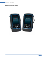
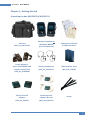
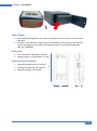
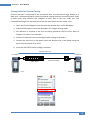
User Manual
Copper Certification Testing
User Manual – WireXpert v7.0.0
WireXpert4500_Copper_IT_EN_U_201506_100
Copyrights 2015 Psiber Data Pte Ltd, a Softing Company
WireXpert - User Manual
WX Series, (WX4500, WX500)
2
WireXpert - User Manual
Notices
No part of this manual may be reproduced in any form or by any means (including electronic storage
and retrieval or translation into a foreign language) without prior agreement and written consent
from Psiber Data as governed by international copyright Laws.
Warranty
The material contained in this document is provided “as is,” and is subject to being changed,
without notice, in future editions. Further, to the maximum extent permitted by applicable law,
disclaims all warranties, either express or implied, with regard to this manual and any information
contained herein, including but not limited to the implied warranties of merchantability and
fitness for a particular purpose. Psiber Data shall not be liable for errors or for incidental or
consequential damages in connection with the furnishing, use, or performance of this document
or of any information contained herein. Should Psiber Data and the user have a separate written
agreement with warranty terms covering the material in this document that conflict with these
Terms, the warranty terms in the separate agreement shall control.
A CAUTION notice denotes a hazard.
It calls attention to an operating procedure, practice, or the like that, if not correctly performed or
adhered to, could result in damage to the product or loss of important data. Do not proceed beyond
a CAUTION notice until the indicated conditions are fully understood and met.
Operating procedure, practice, if not correctly performed or adhered to, could result in personal
injury or death. Do not proceed beyond a WARNING notice until the indicated conditions are fully
understood and met.
General Safety Information
Do not use the device if it is damaged. Before you use the device, inspect the casing. Look for cracks
or missing plastic. Do not operate the device around explosive gas, vapor, or dust.
Always use the device with the cables provided.
Observe all markings on the device before establishing any connection.
Turn off the device and application system power before connecting to the I/O terminals.
When servicing the device, use only the specified replacement parts.
Do not operate the device with the cover removed or loosened.
Use only the power adapter provided by the manufacturer to avoid any unexpected hazards.
3
WireXpert - User Manual
If the device is used in a manner not specified by the manufacturer, the device protection may be
impaired.
Always use dry cloth to clean the device. Do not use ethyl alcohol or any other volatile liquid to clean
the device.
Do not permit any blockage of the ventilation holes of the device.
Environmental Conditions
This instrument is designed for indoor use and in an area with low condensation. The table below
shows the general environmental requirements for this instrument
Environmental conditions
Requirements
Operating Temperature
0 °C to 40 °C
Operating humidity
20% to 85% RH non-condensing
Relative humidity
10% to 80%
The WX4500, WX500 complies with the following Safety and Regulatory requirements.
DIN EN 55024, Edition:2003-10 (IEC/CISPR 24:1997, modified + A1:2001 + A2:2002); EN 55024:1998 +
A1:2001 + A2:2003
DIN EN 55022; VDE 0878-22:2008-05 (IEC/CISPR 22:2005, modified + A1:2005); EN 55022:2006 +
A1:2007
Regulatory Markings
The CE mark is a registered trademark of the
European Community. This CE mark shows
that the product complies with all the
relevant European Legal Directives.
4
WireXpert - User Manual
Declaration of Conformity
Manufacturer‘s Name
Psiber Data Pte. Ltd
Manufacturer’s Address
3 Science Park Drive #03-08,
The Franklin Singapore Science Park 1,
Singapore 118223
Declares under sole responsibility that the product as originally delivered
Model Number
WireXpert, WX4500-FA, WX500
Description
Cable Certification Tester Kit
Equipment
Cable Certifier
Complies with the essential requirements of the following applicable European Directives and carries
the CE marking accordingly:
DIN EN 55024, Edition:2003-10 (IEC/CISPR 24:1997, modified + A1:2001 + A2:2002); EN
55024:1998 + A1:2001 + A2:2003
DIN EN 55022;
VDE 0878-22:2008-05 (IEC/CISPR 22:2005, modified + A1:2005);
EN 55022:2006 + A1:2007
Signature
Arvind C Patel
Quality Management
Psiber Data Pte. Ltd.
www.psiberdata.com
Date :
December 14, 2010
5
WireXpert - User Manual
Contents
Chapter 1: Getting Started ................................................................................................ 7
Unpacking the box (WX4500-FA/WX500-FA) ............................................................................ 7
Key differences between WX4500 and WX500 ......................................................................... 8
WireXpert Overview ................................................................................................................ 10
Dual Control System (DCS) ....................................................................................................... 11
WireXpert Adapters ................................................................................................................. 12
Copper Cable Certification Testing .......................................................................................... 12
Memory.................................................................................................................................... 13
Battery Information ................................................................................................................. 13
Power Supply ........................................................................................................................... 15
Dimension ................................................................................................................................ 15
Environmental Conditions ....................................................................................................... 15
Chapter 2: Configuring WireXpert ................................................................................... 16
WireXpert User Interface ......................................................................................................... 16
Touch Screen Layout ................................................................................................................ 16
The One Touch Access Buttons................................................................................................ 17
WireXpert Firmware ................................................................................................................ 35
Chapter 3: Setting Reference .......................................................................................... 38
Chapter 4: Configuring an AUTOTEST .............................................................................. 39
Testing Guide for Permanent Link Testing............................................................................... 41
Testing Guide for Channel Testing ........................................................................................... 42
Chapter 5: Performing an AUTOTEST .............................................................................. 43
NEXT and RL Fault Locating...................................................................................................... 45
Managing test result(s) ............................................................................................................ 46
Exporting test results into eXport PC Software ....................................................................... 48
USB Flash Drive ........................................................................................................................ 48
Direct connection via USB cable .............................................................................................. 52
Appendix A: Icons Glossary ............................................................................................. 55
Technical Support ................................................................... Error! Bookmark not defined.
6
WireXpert - User Manual
Chapter 1: Getting Started
Unpacking the box (WX4500-FA/WX500-FA)
Soft case
(WX_AC_SOFTCASE)
WireXpert WX4500 or
WireXpert WX500
(Local and Remote)
Calibration Certificate
& USB Flash Drive
Power Adapters Input: 100-240VAC/0.8A
Output: 12VDC/3.0A
(WX_AC_CHARGER)
Talk-set headphones
(WX_AC_TALKSET1)
LCD Protective Cover
(WX_LCD_COVER)
CAT 6A Channel
adapters
(WX_AD_6ACH2)
Permanent Link
adapters & cords
(WX_AD_6ALKIT2)
Straps
7
WireXpert - User Manual
Key differences between WX4500 and WX500
Feature
WX4500
WX500
Frequency of measurement
2500 MHz
500 MHz
Accuracy Specification
Level 2G
Level IIIe
Fiber Testing option
Yes
No
Class FA/CAT 8 options
Yes
No
Patch Cord Test adapters
Yes
Yes
8
WireXpert - User Manual
For Users of WireXpert Software 6.x and Earlier
The software on WireXpert since version 7.x features notable changes on the interface.
These improvements have been made emphasizing on loading time, responsiveness and
stability. The main functions from the previous version remains unchanged.
The new interface is clean and simple, providing quick settings selection and distinct
identification between the Local and Remote units. Booting up is faster and hardware
remains compatible.
Main changes from previous version:
Status bar
1.
Units can now be identified by the background colours on boot up.
2.
Device name function is removed.
3. Connection between devices can now be identified by the Talk set icons.
Devices are not connected.
Devices are connected. Press icon to activate “Talk set Mode”
Devices are connected in “Talk set Mode”. Use headset provided in kit.
4.
5.
Available storage can now be found in System Settings > Settings 2 > Storage
Battery information can now be found System Settings > Settings 2 > Battery
SETUP > Test Settings
1. Quick Setup can now be found in the main SETUP page
2. Site and Label Source can now be found in Project Settings
SETUP > System Settings
1. Operator and Auto Save Results can now be found in Project Settings
SETUP > Device Info
1. Device Info can now be found in System Settings > Settings 2 > Device Info
9
WireXpert - User Manual
WireXpert Overview
Power ON/OFF button
Touch sensitive color LCD screen
USB device port
Audio port
USB host connector for flash drive
RJ-45 Ethernet port for remote control
Power supply port (12V)
One-Touch access buttons
Brightness control button
Navigation scroll buttons
Context sensitive Help button
Probe interface connector
Battery compartment
Item
Functionality
Power ON/OFF Button
To turn on the device, press the power button for 5
seconds.
To turn off the device, press the power button, and
select OK on the power off dialog box. Alternately,
press and hold the power button for 10 seconds (not
recommended). The LED in the power button turns
freen if the unit is turned on.
The LED on the power button turns red when the
device is charging in standy-by mode, orange if it’s
turned on.
Touch Sensitive LCD screen
Performs test executions and viewing of results.
USB device port
Enables remote connection to the PC for remote
control update and exporting saved results.
Audio port
Enables vocal communication between Local and
Remote units when connected to talk set headphones
(WX_AC_TALKSET).
USB Host port
Enables results to be exported and firmware upgrade
via USB flash drive.
Enables loading of custom limits and labels for list
based testing.
10
WireXpert - User Manual
RJ-45 Ethernet port
Enables communication between two sets of WireXpert
for Alien Crosstalk testing.
Power Supply port
Performs charging of device when connected to power
adapter shipped with WireXpert.
One-touch access buttons
Main functional buttons AUTOTEST, SETUP, DATA and
TOOLS for WireXpert. Enables quick AUTOTEST and
results viewing in a single click.
Brightness Control
Adjusts the brightness level of the LCD display.
Navigation scroll buttons
Performs navigation in long lists.
Context sensitive help
Provides simple explanation relevant to the
functionality on the current screen (available in future
version).
Probe interface connector
When connected with different probe adapters (e.g.
CAT6A channel or Permanent Link), WireXpert will
enable specified certification test to be conducted.
Battery compartment
Battery storage compartment. Unscrew to replace
battery (WX_AC_BATT).
Dual Control System (DCS)
WireXpert consists of two identical devices, Local and Remote, for dual-end testing and
certification. Both devices utilise easy to use LCD touch-screen technology and graphical
user interface. The DCS ensures the same graphical data on the Local units are received on
the Remote unit real-time, improving efficiency and productivity significantly as test data
and settings can be viewed from Remote and Local side.
In the event of a wire map failure, the DCS will enable the operator on the far-end to visually
identify which pair of wires is causing the error, instead of just a LED indication on
traditional testers.
2m
30m
2m
10 m
2m
Traditional tester with single display screen, usually
on Local unit only
2m
30m
2m
10 m
2m
WireXpert with LCD screens display on both Local
and Remote units
11
WireXpert - User Manual
WireXpert Adapters
All test adapters are designed to fit onto every WireXpert units. The device automatically
detects adapters when connected and prompts to change in the matching interface
depending on the type of adapter. Via SETUP > “Quick Setup”, the matching limite can be
selected automatically to the type of adapter.
Link and Channel Adapters
Every standard WireXpert kit includes adapters for testing copper cablings in Permanent
Link and Channel configurations.
Channel adapters connect to the patch cords at the wall plates and telecommunication
panels. WireXpert software compensates for the adapter’s transmission characteristics to
ensure test results’accuracy.
Permanent Link adapters connect to the wall plates and telecommunication panel jacks.
WireXpert software compensates for the adapter’s transmission characteristics to ensure
test results will not be affected.
WireXpert’s Permanent Link adapters’ high precision interface reduces the degrading issue
between the RJ-45 jack and link cord, providing highly accurate and repeatable
measurements, and cost efficient method of replacing the link cords instead of the
expensive link adapters.
Adapter Configuration Warnings
WireXpert will display a warning a potential conflict is detected between the adapter and
the test settings. It is important to use the appropriate adapters as accuracy of
measurements will be affected.
Cabling Certification and Testing
Certification testing with WireXpert is highly intuitive and simple. The AUTOTEST function
performs a series of measurements between the Local and Remote devices and analyses the
results to determine if the cabling run passes or fails the selected standards.
Copper Cable Certification Testing
Test at both ends of structured twisted pair cables for the worst case performance are
required in accordance to the ISO/TIA standards. All certification testing requires a two-part
test consisting of a main and remote unit, both bearing similar test capabilities. The test
would be conducted with one end from the telecommunication closet, and the other at the
outlet.
12
WireXpert - User Manual
There are two primary considerations regarding the test method:
•
•
Whether the user patch cords are included in the cabling run during the test.
> If so, channel test configuration is required.
> If not, link test configuration is required.
Which standard – TIA or ISO should be used (Category or Class)
Permanent Link Configuration Tests
The Permanent Link configuration is generally used in facilities still under construction and
does not include user patch cords. As the link configuration does not include the two
additional connections of the patch cords, performance standards are more stringent.
Special link adapters are used on both local and remote units for links that are under test.
Channel Configuration Tests
User patch cords are included for the Channel configuration. The pass/fail limits for this
configuration allows performance degradation inherent in the two additional patch cords
included in the measurements, thus are less stringent. Special channel adapters are used on
both local and remote units for channels that are under test.
Memory
1 Gigabyte internal flash memory.
External USB Flash Drive included allows for flexible data management and storage.
Memory Requirements
The amount of memory that each test result takes up depends on the options that is
configured before starting the test. If plots are saved with each test, file size of test results
will be generally larger than one that has plots option omitted.
WireXpert allocates approximately 1 GB of internal flash memory for test result storage.
Battery Information
WireXpert units are powered by Lithium Ion rechargeable batteries. These batteries contain
circuitry that reports their state of charge to WireXpert. The units can be powered by
external AC/DC power adapters.
A fully charged battery can operate WireXpert for five to eight hours before requiring
recharging. Reducing the screen brightness and enabling the sleep function allows
WireXpert to run longer on a charge.
13
WireXpert - User Manual
Do not set reference or operate WireXpert while the battery is hot immediately after
charging.
Make sure that the WireXpert is always operated within the allowed temperature reange
from 0-40oC. If a significant increase or devrease of the temperature is discovered,
repeat the set reference procedure to remain the instrument’s accuracy.
Use only the supplied power supplies with the WireXpert kit. Using other powers may
damage the tester and void its warranty.
Battery Safety
1. To avoid the risk of fire, burns or damage to your battery pack, do not allow metal
objects to touch the battery contacts.
2. The battery pack is suitable for use only with compatible WireXpert devices.
3. Do not disassemble the battery pack. There are no user serviceable parts inside. Do
not dispose the battery pack in fire or water.
4. Handle a damaged or leaking battery with extreme care. If you come into contact
with the electrolyte, wash the exposed area with soap and water. If the electrolyte
contacts the eye, flush the eye with water for 15 minutes and seek medical attention.
5. Do not expose the battery pack to high storage temperatures (above 55°C).
6. When discarding a battery pack, contact your local waste disposal provider regarding
local restrictions on the disposal or recycling of Lithium Ion batteries.
7. To obtain a replacement battery (part number WX_AC_BAT1), contact your local
dealer.
8. Do not charge the battery pack if the ambient temperature is above 40°C.
Replacing Battery
The batteries are located and secured at the bottom of the WireXpert units for safety
reasons. To replace the batteries;
1.
2.
3.
4.
Switch off WireXpert and disconnect external power supplies.
Unscrew the battery compartment and remove the cover.
Remove and replace a new battery into the compartment.
Close, fasten and secure the screw onto the compartment cover.
14
WireXpert - User Manual
Power Supply
•
•
Removable/rechargeable Li-Ion batteries provide more than 8 hours of continuous
operation.
AC power: 100~240V AC plugs directly into the battery. Alternatively, the batteries
can be recharged using an external charging kit that can be ordered separately
(WX_AC_CHARGER).
Dimension
•
•
Size: 220mmH x 110mmW x 53mmD
Weight: approx. 1.0 kg (approx. 2.2 lbs.)
Environmental Conditions
•
•
•
Operating temperature: 0°C to 40°C
Storage Temperature: 20°C to 60°C
Relative humidity: 10% to 80%
H
W
D
15
WireXpert - User Manual
Chapter 2: Configuring WireXpert
WireXpert User Interface
Touch Screen Layout
The Graphical User Interface (GUI) in version 7.0’s firmware has been updated with a more
responsive system and quick-access menus.
WireXpert boots up to the SETUP screen. It is categorised into 5 groups:
1. Status bar
2. Quick Setup group
3. Test Settings group
4. Project Settings group
5. System Settings group
1. The Status bar displays the current date and time, talk set and battery level.
2. The Quick Setup group provides quick selection with predefined configurations.
3. The Test Settings group provides results oriented configurations necessary to
perform an AUTOTEST.
4. The Project Settings group provides non-results oriented configurations before
performing an AUTOTEST.
5. The System Settings group settings provides device, time, localization and device
related configurations.
16
WireXpert - User Manual
The One Touch Access Buttons
The fundamental philosophy behind the WireXpert User Interface is simplicity in its ease of
use. The main functions of the One-Touch access buttons as follows:
AUTOTEST
The “AUTOTEST” button will perform an immediate certification test on the
last configured settings. If no settings were configured, default settings will be
used.
Test results will be generated automatically after the test is completed.
You will receive any of the following 4 results after the “AUTOTEST”:
•
Green “PASS” – Good test result in accordance to pre-defined settings
•
Green “PASS*” – “PASS” result with one or more test parameters that have margin in
the range of uncertainty of the tester.
•
Red “FAIL” – Unacceptable results with severe disturbance on one or more test
parameters.
•
Red “FAIL*” – “FAIL” result with one or more test parameters that have negative
margin in the range of uncertainty of the tester.
Note: Marginal Pass/Fail is enabled by default. Press the “SETUP” button >Test Settings >
Test Options > Lab > Marginal Pass/Fail to change the presentation of the test result to clear
“PASS” or “FAIL” results. Uncertainty of the tester is then not taken into account. Contact
Psiber Data for more information.
You will be given the following option after performing an AUTOTEST:
•
•
•
“Retest” can be conducted on a PASS or FAIL result (if list based testing labeling
scheme is selected).
“View” details will display additional test parameters and plots.
“Save” test results to device
An “AUTOTEST” will fail in the event of missing connection between the Local and Remote
units, wrong settings configured or if setting reference is required. WireXpert will perform
an initial wire map test before testing other parameters. Disable wire map test at Test
Settings > Test Options > Lab > Wire map to bypass this test.
17
WireXpert - User Manual
AUTOTEST results
“View” detail results
Plots
The type of results will differ depending on the Test Limits and type of cable.
SETUP
The “SETUP” button provides setting options necessary to conduct an AUTOTEST
and configure the device.
These options include –
Quick Settings
Quick Settings provides quick selection using predefined TIA (CAT 5e/6/6A) and ISO (Class
D/E/EA/FA) configurations for UTP/FTP cables. WireXpert will detect if Channel or
Permanent Link adapter is used and changes its test limits automatically.
18
WireXpert - User Manual
Test Settings
Test Settings provides results oriented configurations necessary to perform an AUTOTEST.
Test Limit
Choose from a list of standards to determine the performance criteria in a given category or
class. Three of the most commonly used limits will be listed in the “Recent Limit” list.
Press the SETUP button > Test Settings > Test Limits to choose from a list of commonly used
limits. Three recently used limits will be on top of the list.
Cable
Choose from a list of cable manufacturer for more specific test parameters. If unsure of
manufacturer, choose “Generic UTP” or “Generic Shielded”, or “Customized Cable” to
create custom cable.
Press the SETUP button > Test Settings > Cable Manufacturer to choose from a list of cable
manufacturers. If unsure of manufacturer, choose “Generic UTP” or “Generic Shielded”, or
“Customised Cable” to create custom cable.
Customized Cable
Click “Add” to add or “Delete” to remove customized cable(s) from the customised cable list.
19
WireXpert - User Manual
Add customised cable
Manage customised cables
When creating customised cable, determining the cable name, number of pairs,
construction type, performance grade(S/FTP) and cable’s NVP is required.
WireXpert introduces the “Manage” button on version 7.0
firmware. “Manage” enables multiple saved items such as sites,
operators, customized cables, customized connectors and
results to be selected and deleted simultaneously.
NVP
Determine the Nominal Velocity of Propagation (NVP) value of the cable. The NVP factor is
required to determine the accurate length of the cable run to be measured. Based on this
constant value, the WireXpert performs it’s TDR calculations. Please see the cable’s data
sheet for the specific value of the cable type in use.
If the specfic NVP value is unknown, go to TOOLS > “Learn NVP” to determine the value
using the predefined cable run of at least 30 meters or 100 feet.
20
WireXpert - User Manual
Connector
Press the SETUP button > Test Settings > Cable Manufacturer to choose from a list of
connector manufacturers. If unsure of manufacturer, choose “Generic UTP” or “Generic
Shielded”, or “Customised Connector” to create custom cable.
Click “Add” to add or “Delete” to remove customised connector(s) from the customised
connector list.
Add customized cable
Manage customized cables
21
WireXpert - User Manual
Advanced Test Options
Advanced Test Options determines how the test will be conducted and results will be
displayed.
General
o Locator – If enabled, WireXpert will display NEXT and Return Loss (RL) fault information
in an AUTOTEST result. Disabled by default.
o Cable Pairing Type – Choose T568A or T568B copper cable wiring standard. “B” selected
by default.
o Start AUTOTEST On Connection – If enabled, WireXpert will perform AUTOTEST as soon as
a connection between Local and Remote is established. Disabled by default.
o Direct Attach – If enabled, WireXpert will perform Direct Attach copper installation test.
Attach Permanent Link adapter to the Local and Patch Cord adapter to the Remote unit
to perform this test. Connect Local unit to patch panel and Remote to field terminated
end. Disabled by default.
o AC Wire map – If enabled, WireXpert is able to measure test runs with Power over
Ethernet (PoE) midspan devices in between. The WireXpert supports cable runs with
IEEE 802.3 af and 802.3 at injectors. Disabled by default.
Lab
Labratory use only. Please contact your local WireXpert Vendor for more information.
o WireMap Test – If enabled, WireXpert will ignore failed wire maps during test. Enabled
by default.
o Marginal Pass/Fail –If enabled, WireXpert will display marginal pass (PASS*) and
marginal fail (FAIL*) results. Enabled by default.
o Save Phase Data – If enabled, WireXpert will generate information for phase data plot
generation. Export saved results to CSV format using eXport software to obtain phase
data. Impedance plot will be displayed on eXport. Disabled by default.
o 3/4 dB Rule – If enabled, WireXpert will ignore RL failures if Insertion Loss (IL) is <3dB
and NEXT failures if IL is <4dB. Disabled by default.
Project Settings
Project Settings provides non-results oriented configurations before performing an
AUTOTEST.
22
WireXpert - User Manual
Site
To add a site,
1. Press the SETUP button > Project Settings > Site to begin adding a new site.
2. Click the “Add” button to add a new site.
3. Enter a Site Name. Site Name is a required field. Test results and label source will be
saved under the created Site.
4. Site Address and Site Notes are optional fields, but they provide additional
information of the site.
5. Press “OK” to save site and proceed.
By default, WireXpert creates an “UNSPECIFIED” site for default saving as long as new sites
are not created.
To delete a saved site,
1. Press the “Manage” button.
2. Select site(s) and press the “Delete” to delete site(s).
WireXpert introduces the “Manage” button on version 7.0
firmware. “Manage” enables multiple saved items such as
sites, operators, customized cables, customised connectors
and results to be selected and deleted simultaneously.
23
WireXpert - User Manual
Operator
To add a site,
1.
2.
3.
4.
Press the SETUP button > Project Settings > Operator to begin adding an operator.
Click the “Add” button to add a new operator.
Enter Operator Name.
Press “OK” to save site and proceed.
By default, WireXpert creates an “UNSPECIFIED” operator for default saving if new
operators are not created.
To delete a saved operator,
3. Press the “Manage” button.
4. Select operator(s) and press the “Delete” to delete operator(s).
Label Source
Press the SETUP button > Test Settings > Label Source to choose from a list of scheme.
24
WireXpert - User Manual
Template Label
None
Manual input of label names is required for every saving of result.
Simple Label
Provides simple numeric increments to a prefix. To configure the simple label scheme:
1. Enter desired Prefix (e.g. Office, Company X)
The prefix will remain unchanged by every result.
2. Set a numeric start value (e.g. 1, 33, 245)
The counting value will raise one number with every test made.
Template Label
TIA-606-A Class 1 (Single Room Horizontal Link)
TIA-606-A Class 1 standard labelling scheme mainly used to support labelling for a building
or premises that is served in a single equipment room or a horizontal cross-connect.
25
WireXpert - User Manual
The default “1A-A1” generally refers to “Floor + Tel Room – Panel + Port”.
TIA-606-A Class 2 (Single Building Horizontal/Single Building Backbone Cable)
TIA-606-A Class 2 standard labelling scheme, mainly used to support labelling of
infrastructure with one or more telecommunication spaces in a single building.
The default “1A-A1” for Horizontal Link generally refers to “(1) Floor + (A) Tel Room – (A)
Panel + (1) Port”.
The default “1A/1B-” for Backbone Cable generally refers to “(1)Tel Room 1 Floor + (A)Tel
Room 1 Name / (1)Tel Room 1 Floor + (B)Tel Room 2 Name” followed by - “Backbone Cable .
Cable”
TIA-606-A Class 3 (Campus Backbone Cable)
TIA-606-A Class3 standard labelling scheme, mainly used to support labelling for multiple
buildings in a single site.
26
WireXpert - User Manual
The default “A-1A/A-1A-” generally refers to “(A)Building 1 Name - (1)Tel Room 1 Floor +
(A)Tel Room 1 Name / (A)Building 2 Name – (1)Tel Room 2 Floor + (A) Tel Room 2 Name”
followed by - “Backbone Cable . Cable”
Free Form
Free Form provides simple numeric increments to 2 or more prefix.
The default start “A-1” and end “B-5” labels will generate labels “A1 to A5 and B1 to B5”.
List Based Testing
List based testing allows creation of label list in the eXport software on PC and then bring
the list to WireXpert. It further allows easy selection of labels from the list to help
technician select the cables to be tested quickly. This testing method is carefully optimized
for typical test work-flow, and it significantly improves productivity.
1. Insert USB flash drive to USB port on WireXpert.
27
WireXpert - User Manual
2.
3.
4.
5.
6.
Device will automatically detect USB flash drive.
Select “Label List”.
Select the custom label list(s) to be copied from the USB flash drive.
Press “Copy label files from USB” to proceed.
Click “OK”.
7. Press the “SETUP” button > Project Settings > Label Source > List Based Testing
8. Select label source file and click “OK” to continue.
Refer User Manual – eXport for more information on generating list based labels.
9. Press the AUTOTEST button to display the loaded cable list.
10. Select label from list to begin AUTOTEST.
11. WireXpert will automatically save a PASS result and return to the list, or allows you
to save or conduct a re-test for a FAIL result manually.
28
WireXpert - User Manual
12. Select a tested label to view the results. A green result indicates a PASS and a red
result indicates a FAIL test. A re-test can be conducted by pressing “Retest”.
13. Press the AUTOTEST button to return to the list.
AutoSave
Enable option for WireXpert to auto save every PASS result.
System Settings
Length Unit
Press the SETUP button > System Settings > Settings 1 > Device Settings > Length Unit to
select the preferred length unit to be displayed. Feet (FT) and Meters (M) are available.
Plot Y-axis Direction
Press the SETUP button > System Settings > Settings 1 > Device Settings > Plot Y-axis
Direction to select the how the plot’s Y-axis will be display. Normal and Inverted Y-axis are
available.
Sleep and Auto Power-off Interval
For Sleep Interval,
Press the SETUP button > System Settings > Settings 1 > Sleep Interval to select the idle
duration before WireXpert enters the sleep (power saving) mode.
For Auto Power-off Interval,
Press the SETUP button > System Settings > Settings 1 > Auto Power-Off Interval to select
the idle duration before WireXpert performs an automatic shutdown.
29
WireXpert - User Manual
Audio Settings
Press the SETUP button > System Settings > Settings 1 > Audio Settings to configure various
audio options for WireXpert.
Touch Click – Enable option to trigger clicking sound
options on screen touch.
Speaker & Tone – Enable option to trigger system
sound options, e.g., boot up.
Voice Prompt – Enable option to trigger system vocal
notifications on action.
Volume Control – Adjust for audio loudness.
Date and Time
Press the SETUP button > System Settings > Settings 2 > “Date & Time to configure date,
time and display format.
30
WireXpert - User Manual
Date settings
Time settings
Language
Press the SETUP button > System Settings 2 > Language to select preferred display language.
Storage
Press the SETUP button > System Settings > Settings 2 > Storage to view available storage
space on WireXpert and USB flash drive if inserted.
Read USB flash drive by clicking the USB icon if prompt did not appear or closed after
inserting USB flash drive.
31
WireXpert - User Manual
Read USB flash drive
Battery
Press the SETUP button > System Settings > Settings 2 > Battery to view battery level.
Battery levels of Local and Remote will be displayed if units are connected
Restore Factory Settings
Press the SETUP button > System Settings 2 > Settings 2 > Restore Default Settings to restore
WireXpert to factory settings. Click “OK” to begin restoration.
32
WireXpert - User Manual
Restoring WireXpert to default settings is an irreversible action. All user defined settings
and stored will be erased and cannot be recovered.
Touch Screen Calibration
Press the SETUP button > System Settings > Settings 2 > Touch Screen Calibration to readjust mechanical alignments of the touch screen. Follow on-screen instructions to begin
calibration.
Device Info
Press the SETUP button > System Settings > Settings 2 > Device Information to check the
device and probe serial numbers, software and hardware version numbers, device last
calibrated date and probe test count.
33
WireXpert - User Manual
Click on the “Info” button for more information on the firmware.
To ensure accurate test results, it is recommended to have WireXpert units calibrated
every year. Contact vendor for more information.
DATA
The “DATA” button provides archive and data management ability to saved sites
and test results. Saved test results can be renamed or deleted in this option.
View results
Manage results
Note: Deleting a site will also delete its containing test results.
34
WireXpert - User Manual
TOOLS
The “TOOLS” button provides advanced options for in-depth troubleshooting and
expert WireXpert users. These options include-
Requires:
Local and Remote
Set Reference – Performs loss
compensation through
calculation from setting of
referencing point.
Requires:
Local and Remote
Learn NVP – Performs a test to
determine the NVP of the
cable using the length value
programmed by the user
Requires:
Local or Remote
Length & Delay – Performs a
test to determine the length
and propagation delay of each
pair using the NVP value
programmed by the user.
Requires:
Local and Remote
Wiremap – Verifies the correct
wiring and detects split pairs
Requires:
Local or Remote
Reset Probe – Resets Perm.
Link adapter usage count once
a new link cord is in place
About – Displays worldwide
contact information for Psiber
Data and Softing.
Note: 30 meters (100 feet) cable
length is at least required to get a
valid NVP value!
WireXpert Firmware
Adapter Detection
WireXpert firmware detects which adapters are connected to the Local and Remote units
and configures the testing program to match these adapters. Test limits are automatically
changed to the type of adapter (Channel or Permanent Link) upon a Quick Setup selection.
For instance, if a Channel adapter is attached and a CAT6 profile is selected the limit is
automatically configured for CAT6 Channel Testing.
Digital Fault Finding
WireXpert software automatically pinpoints cable fault locations and causes, speeding
problem resolution and increasing operator productivity.
Applications
WX4500 provides complete certification solutions to major copper cabling and fiber optic
installations. Depending on requirements, separate kits, components or customised
adapters can be purchased to provide more specialised tests and certifications.
35
WireXpert - User Manual
WX500 provides the best cost efficient solution for installers who wish to certify only up to
Cat6A. WX500 runs on the same hardware and firmware as WX4500, but is calibrated to test
only up to 500MHz.
For a list of available adapters, please visit www.psiberdata.com.
Data Management
WireXpert data management software, eXport, enables management of saved results such
as finding, renaming, deleting, printing and creating custom labels. Please refer to User
Manual – eXport for more information.
Adapter Configuration
WireXpert uses different adapters to test and certify different cabling runs. The device
automatically detects which adapters are attached and selects matching test parameters.
Adapter Insertion Counts
Every WireXpert adapter can keep track of the number of tests performed. This data
ensures up to date information on the adapter’s lifespan. WireXpert will indicate a warning
when the adapter insertion counts has expired the specified insertion counts lifespan. This
can be checked by pressing the “SETUP” button > System Settings 2 > Device Info > Probe
Test Count
Upgrading the firmware
Upgrade WireXpert firmware to ensure latest test standards and device features are up to
date. To upgrade WireXpert’s firmware,
•
•
•
•
•
Download and install the latest build of eXport software from psiberdata.com
Export the firmware using an USB flash drive
Backup the test results in the device
Insert the flash drive to the USB port on WireXpert
Choose the upgrade firmware option and click “Yes” to begin upgrade
If the upgrade prompt do not appear after inserting the USB flash drive, press the SETUP
button > System Settings 2 > Storage > USB and select “Upgrade Firmware”.
Upgrading from an older version (< v7.0.0)
Upgrading from older version is possible by following the same procedures. WireXpert will
detect the firmware from the USB flash drive and upgrade the firmware.
36
WireXpert - User Manual
If the Upgrade prompt did
not appear, press SETUP
button > System Settings 2
> Storage and click the USB
button to launch the
prompt manually
Upgrade prompt
Test results and custom data in the device will be permanently removed during firmware
upgrade. Please export all results and data to USB flash drive before proceeding.
37
WireXpert - User Manual
Chapter 3: Setting Reference
It is recommended to perform a set reference measurement if the Local and Remote units
are being paired for the first time. If there is a mismatch in firmware versions or expired
calibrations, AUTOTEST will be denied.
To set reference,
1. Connect a Permanent Link adapter to the Local unit.
2. Connect a Channel adapter to the Remote unit.
3. Connect the 2 units together using the patch cord provided in the kit.
4. Press the TOOLS button > Set Reference
5. Set Reference will fail in the event of•
•
•
Adapter probe mismatch, i.e., two channel or permanent link adapters
Firmware version mismatch between Local and Remote units
No connection between Local and Remote units
38
WireXpert - User Manual
Chapter 4: Configuring an AUTOTEST
After configuring the system settings, follow these steps to set up an AUTOTEST.
1. Press the SETUP button > Project Settings
a. Site – Create or select a Site
b. Operator – Create or select an Operator
c. Label Source – Select cable labelling scheme. Load labels from USB flash drive
if using List Based Testing (LBT).
d. AutoSave – Enable option for WireXpert to auto save every PASS result.
2. Press the SETUP button > Quick Setup to select pre-defined test limit settings using
matching generic UTP/FTP cable and FTP connector.
3. Manual Setup – Press the SETUP button > Test Settings
a. Test Limit – Select a test limit
b. Cable – Create a custom or select cable from list. Select “Generic” if unsure.
c. Connector - Create a custom or select connector from list. Select “Generic” if
unsure.
d. Test Options > General
i. Locator – Enable option to display the worst NEXT and Return Loss (RL)
fault information in an AUTOTEST result. Default has been set to OFF.
ii. Cable Pairing Type – Select if cable under test is paired using the
T568-A or T568-B standard.
iii. Auto Test on Connection – Enable option to perform AUTOTEST on , i.e,
as soon as the connection between Local and Remote units is
established. Default option has been set to OFF.
iv. Direct Attach – Enable option only if performing Direct Attach
installation test. Default option has been set to OFF.
v. AC Wire map – Enable option to bypass testing DC parameters.
Default option has been set to OFF.
39
WireXpert - User Manual
Please ensure you have the following components before conducting the test;
•
WireXpert, Local & Remote units (WX4500)
Permanent Link Testing
•
2 x Permanent Link Adapter (WX_AD_6APL2)
•
2 x Patch Cord (WX_AC_6ALCORD2)
Channel Testing
•
2 x Channel Adapter (WX_AD_6ACH2)
Do not connect WireXpert to a voltage source such as an active telephone jack. Excessive
voltage will damage the units and the adapter and void the warranty.
40
WireXpert - User Manual
Testing Guide for Permanent Link Testing
Permanent Link (PL) test is comprised of the connection from a patch panel to a
telecommunication outlet (horizontal cabling) using Permanent Link test adapters at each
end of the link under test.
1. Insert the Permanent Link adapters into the Local and Remote units of the WireXpert.
2. Power ON WireXpert. Check that WireXpert is in Copper testing mode.
3. Set reference is required if the units are being paired for the first time. Refer to
Chapter 2 on how to set reference.
4. Choose the Permanent Link limits and configure other settings if necessary.
5. Connect the Local unit to the patch panel and Remote unit to the outlet using the
patch cord provided.
6. Press the AUTOTEST button to begin AUTOTEST.
Link under test
PL adapter
PL adapter
Patch Panel
Local
Horizontal Cabling
Outlet
Remote
41
WireXpert - User Manual
Testing Guide for Channel Testing
Channel (Ch) test is comprised of the connection from an active device (egg. Router) in a
data rack, a telecommunication outlet (horizontal cabling) and the connecting patch cords
at both ends using Channel test adapters at each end of the link under test. The
recommended length for the patch cord from the patch panel and the outlet is 5m.
1. Insert the Channel adapters into the Local and Remote units of the WireXpert.
2. Power ON WireXpert. Check that WireXpert is in Copper testing mode.
3. Set reference is required if the units are being paired for the first time. Refer to
Chapter 2 on how to set reference.
4. Choose the Channel limits and configure other settings if necessary.
5. Connect the Local unit to the patch panel and Remote unit to the outlet using the
patch cord connected to be used.
6. Press the AUTOTEST button to begin AUTOTEST.
Channel under test
Ch adapter
Ch adapter
Patch Panel
Local
Horizontal Cabling
Outlet
Remote
42
WireXpert - User Manual
Chapter 5: Performing an AUTOTEST
Press the AUTOTEST button once settings and limits have been selected. WireXpert will use
the last configuration or factory settings to perform the AUTOTEST if new settings are not
configured.
WireXpert will display summarized result with PASS or FAIL once AUTOTEST is completed.
Press the “View” details button to view the comprehensive result or the “Save” button to
save the results.
AUTOTEST in progress
AUTOTEST complete
“View” results
Click on the parameter to display a more comprehensive individual result.
In plot view, press the “Worst Margin” button to view the worst margin. Press again to view
the “Worst Value” or press the “Manage” button for more options.
Wire map
Insertion Loss
Return Loss
43
WireXpert - User Manual
Attentuation to Crosstalk
Ratio, Far-end
Attentuation to Crosstalk
Ratio, Near-end (ISO only)
Near-end Crosstalk
Power-sum ACRF
Power-sum ACRN (ISO only)
Power-sum NEXT
44
WireXpert - User Manual
Manage plots
Resistance
Length & Delay
NEXT and RL Fault Locating
If the Locator option is enabled in the Test Settings > Test Options, WireXpert will display
extremely critical troubleshooting information in the form of a Time Domain Reflection plot
for NEXT and Return Loss.
Near-End Crosstalk (NEXT) is an undesired effect of interference between two pairs in a
cable measured at the same end of the cable as the interfering transmitter. In crosstalk, the
signals traveling through adjacent pairs of wire in twisted-pair cabling interfere with each
other. Cross talk is undesirable.
The NEXT Locator displays the locations where crosstalk is excessive in the cable and
indicate the exact location in meters or feet from the Local unit of where high crosstalk
issue is seen. View individual plot by selecting/deselecting cable pairs. Each two pairs of
cables that have been tested for crosstalk are represented by different colour in the plot.
Return Loss (RL) is the measurement (in dB) of the amount of signal that is reflected back
toward the transmitter. Impedance mismatches and discontinuities caused by terminations
to plugs or jacks and within the plug/jack connection itself contributes to RL. Excessive
bends and damaged cable will also contribute to RL. The greater the variation in impedance,
the greater the return loss reading.
The RL Locator displays the locations where return loss occurred during an AUTOTEST and
indicates the exact location of where the highest return loss occurs. View individual plot by
selecting/deselecting cable pair. Each pair of cables that has been tested is represented by
different colour in the plot.
Each peak result in NEXT and RL Locator could represent a new joint connection, rarely a
coupler and not necessary a bad cable that requires replacement.
45
WireXpert - User Manual
Locator – To enable, press the
“SETUP” button > Test
Settings > Test Options >
Locator
NEXT Locator
Return Loss Locator
Managing test result(s)
Test results can be manually saved by pressing the “Save” button after an AUTOTEST is
completed. When prompted, enter label name and click “OK” to save.
The “Save” icon will disappear
once saving is completed.
Pass test results will be automatically saved with reference to the selected Label Source
(SETUP > Project Settings > Label Source) when AUTOTEST is completed.
46
WireXpert - User Manual
To view saved results,
1.
2.
3.
4.
Press the “DATA” button.
Select “Copper” or “Fiber” and press the “View” button.
Select the test results click “View” to view results.
Select the next page for more results.
To delete a saved result,
1.
2.
3.
4.
Press the “DATA” button.
Select “Copper” or “Fiber” and press the “View” button.
Press the “Manage” button.
Select result(s) and press the “Delete” to delete result(s).
To rename a saved result,
1.
2.
3.
4.
Press the “DATA” button.
Select “Copper” or “Fiber” and press the “View” button.
Press the “Manage” button.
Select result and press the “Rename” to rename result.
47
WireXpert - User Manual
Exporting test results into eXport PC Software
eXport is a data management software designed to work seamlessly with WireXpert. Saved
results can be exported using the following methods;
USB Flash Drive
1. Insert USB flash drive to USB port on WireXpert.
2. Device will automatically detect flash drive.
3. Otherwise, press the “SETUP” button > System Settings 2 > Storage > USB
4. Select “Test Results”.
5. Click “OK” to proceed.
6. Launch eXport software.
7. Go to File > Create New Project to create new project space.
48
WireXpert - User Manual
8. Go to Import > USB Flash Drive and select the flash drive. Click “Import”.
9. Select database and click “Import Selected” to import or click “Import All” for all
databases.
49
WireXpert - User Manual
50
WireXpert - User Manual
51
WireXpert - User Manual
Direct connection via USB cable
1. Connect WireXpert to your PC using a mini USB cable.
2. Launch eXport software.
3. Go to File > Create New Project to create new project space.
4. Go to Import > Device.
5. Select database and click “Import Selected” to import or click “Import All” for all
databases.
52
WireXpert - User Manual
53
WireXpert - User Manual
Refer User Manual – eXport for more information on how to use the software.
54
WireXpert - User Manual
Appendix A: Icons Glossary
Add – Adds a site, operator or
customised cable, connector
to the database.
Retest – Performs an
AUTOTEST on selected result
on List-Based Testing.
Back – Returns to previous
screen. Unsaved options will
be discarded.
Cancel – Discards option.
Delete – Deletes a site,
operator or customised cable,
connector from the database.
Details – View selected result.
Manage – Enables “Rename”
and “Select all” option.
Format, Reset – Performs nonreversible setting/data
restoration to factory defaults.
Forward – Proceed to the next
screen.
Device info – Displays device
firmware build information.
Okay – Confirms and saves
current option.
Rename – Renames saved test
result in the DATA menu.
Restart – Restarts current
procedure.
Save – Saves current test
result. Icon will disappear after
a successful save.
USB – Reads USB flash drive to
perform upgrade firmware,
test result export or custom
limit and label list import
55
WireXpert - User Manual
Select all – Selects all data on
screen.
Next pair – View next pair of
plots of the current result.
Fibermap – Displays mapping
of fiber being tested.
PO chart, grid – Toggles
between displaying of power
loss in bar chart or grid format
for fiber testing.
Scope live, test – Toggles
between ‘Live’ and ‘Test’
mode when inspecting a
SM/MM fiber with the
inspection scope.
Set Reference – Performs
result referencing between the
Local and Remote units.
Transmit ON/OFF – Toggles
between enabling and
disabling of light source on the
Remote unit.
56
WireXpert - User Manual
Technical Support
Worldwide Offices
Psiber Data’s global presence ensures our customers receives sales and technical support
anywhere around the world.
North America
Softing Inc.
7209 Chapman Highway
Knoxville, TN 37920
Phone: +1 865.251.5252
E-mail: [email protected]
Web: itnetworks.softing.com/us
Asia / Pacific
Psiber Data Pte Ltd
a Softing Company
3 Science Park Drive
#03-09, The Franklin
Singapore Science Park 1
Singapore 118223
Phone: +65-6569-6019 ext. 105
E-mail: [email protected]
Web: apen.psiberdata.com
Europe/Middle East/Africa
Psiber Data GmbH
a Softing Company
Lise-Meitner-Str. 3
82152 Krailling
Phone: +49 (0)89 89136060
E-mail: [email protected]
Web: www.psiberdata.com
Psiber Data China
a Softing Company
Room 208, Building 1, No 388, Tianlin Road
Xuhui District, 200233
Shanghai, China
Phone: +86-21-54133123
E-mail: [email protected]
Web: china.psiberdata.com
Psiber Data France
a Softing Company
87 Rue du Général Leclerc
Creteil, 94000 (Paris)
Phone: +33 66 097 0910
E-mail: [email protected]
Web: www.psiberdata.com
Softing Italia Srl
Via M. Kolbe, 6
20090 Cesano Boscone (MI)
Phone: +39 02 4505171
E-mail: [email protected]
Web: www.softingitalia.it
57