1
Operating Manual
Digital
precision measuring amplifier
DMP40, DMP40S2
B03964.0en
d
3
Contents
Contents
A
Introduction
1
2
3
4
5
6
7
8
Safety instructions . . . . . . . . . . . . . . . . . . . . . . . . . . . . . . . . . . . . . . . . . . . . . . . . . . . . . .
Notes on the documentation . . . . . . . . . . . . . . . . . . . . . . . . . . . . . . . . . . . . . . . . . . . . .
How the DMP amplifier works . . . . . . . . . . . . . . . . . . . . . . . . . . . . . . . . . . . . . . . . . . . .
Housing . . . . . . . . . . . . . . . . . . . . . . . . . . . . . . . . . . . . . . . . . . . . . . . . . . . . . . . . . . . . . . .
Structure of the DMP amplifier . . . . . . . . . . . . . . . . . . . . . . . . . . . . . . . . . . . . . . . . . . . .
Back of the amplifier, port jacks . . . . . . . . . . . . . . . . . . . . . . . . . . . . . . . . . . . . . . . . . . .
Conditions on site . . . . . . . . . . . . . . . . . . . . . . . . . . . . . . . . . . . . . . . . . . . . . . . . . . . . . .
Maintenance and cleaning . . . . . . . . . . . . . . . . . . . . . . . . . . . . . . . . . . . . . . . . . . . . . . .
B
Connecting up
1
2
Mains connection . . . . . . . . . . . . . . . . . . . . . . . . . . . . . . . . . . . . . . . . . . . . . . . . . . . . . . .
Connecting transducers . . . . . . . . . . . . . . . . . . . . . . . . . . . . . . . . . . . . . . . . . . . . . . . . .
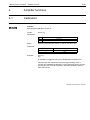
2.1 Possible connections . . . . . . . . . . . . . . . . . . . . . . . . . . . . . . . . . . . . . . . . . . . . . .
2.2 Type of connection . . . . . . . . . . . . . . . . . . . . . . . . . . . . . . . . . . . . . . . . . . . . . . . .
2.3 SG full bridges . . . . . . . . . . . . . . . . . . . . . . . . . . . . . . . . . . . . . . . . . . . . . . . . . . . .
2.4 Auxiliary inputs . . . . . . . . . . . . . . . . . . . . . . . . . . . . . . . . . . . . . . . . . . . . . . . . . . .
B3
B4
B4
B4
B5
B6
3
4
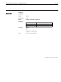
Synchronization . . . . . . . . . . . . . . . . . . . . . . . . . . . . . . . . . . . . . . . . . . . . . . . . . . . . . . . .
Inputs and outputs; remotes . . . . . . . . . . . . . . . . . . . . . . . . . . . . . . . . . . . . . . . . . . . . . .
B7
B8
C
Commissioning
1
2
3
Commissioning . . . . . . . . . . . . . . . . . . . . . . . . . . . . . . . . . . . . . . . . . . . . . . . . . . . . . . . . .
Switch on . . . . . . . . . . . . . . . . . . . . . . . . . . . . . . . . . . . . . . . . . . . . . . . . . . . . . . . . . . . . . .
Choosing dialog language . . . . . . . . . . . . . . . . . . . . . . . . . . . . . . . . . . . . . . . . . . . . . . .
A3
A7
A8
A9
A10
A11
A12
A13
C3
C4
C5
DMP40, DMP40S2
4
Contents
D
Functions and symbols on the DMP
1
2
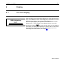
Control elements on the DMP40 . . . . . . . . . . . . . . . . . . . . . . . . . . . . . . . . . . . . . . . . . .
Display . . . . . . . . . . . . . . . . . . . . . . . . . . . . . . . . . . . . . . . . . . . . . . . . . . . . . . . . . . . . . . . .
2.1 The first display . . . . . . . . . . . . . . . . . . . . . . . . . . . . . . . . . . . . . . . . . . . . . . . . . . .
2.2 Display in measuring mode . . . . . . . . . . . . . . . . . . . . . . . . . . . . . . . . . . . . . . . . .
D3
D5
D5
D6
3
Setup mode . . . . . . . . . . . . . . . . . . . . . . . . . . . . . . . . . . . . . . . . . . . . . . . . . . . . . . . . . . .
3.1 Einstellfenster aufrufen . . . . . . . . . . . . . . . . . . . . . . . . . . . . . . . . . . . . . . . . . . . .
3.2 Quit setup window . . . . . . . . . . . . . . . . . . . . . . . . . . . . . . . . . . . . . . . . . . . . . . . .
3.3 Selection menus . . . . . . . . . . . . . . . . . . . . . . . . . . . . . . . . . . . . . . . . . . . . . . . . . .
3.4 Setup window . . . . . . . . . . . . . . . . . . . . . . . . . . . . . . . . . . . . . . . . . . . . . . . . . . . .
D11
D13
D14
D16
D17
E
Setting up the DMP
1
Setting up the amplifier . . . . . . . . . . . . . . . . . . . . . . . . . . . . . . . . . . . . . . . . . . . . . . . . . .
1.1 Measuring range . . . . . . . . . . . . . . . . . . . . . . . . . . . . . . . . . . . . . . . . . . . . . . . . . .
1.2 Scaling and linearization . . . . . . . . . . . . . . . . . . . . . . . . . . . . . . . . . . . . . . . . . . .
1.3 Setting zero/taring . . . . . . . . . . . . . . . . . . . . . . . . . . . . . . . . . . . . . . . . . . . . . . . .
1.4 Low pass filter . . . . . . . . . . . . . . . . . . . . . . . . . . . . . . . . . . . . . . . . . . . . . . . . . . . .
E3
E6
E7
E9
E10
1.4.1 Switching filters . . . . . . . . . . . . . . . . . . . . . . . . . . . . . . . . . . . . . . . . . . . . .
Min / Max store . . . . . . . . . . . . . . . . . . . . . . . . . . . . . . . . . . . . . . . . . . . . . . . . . . .
E12
E13
1.5.1 Deactivate / delete Min/Max store . . . . . . . . . . . . . . . . . . . . . . . . . . . . .
E14
1.5.2 Controlling Min / Max storage . . . . . . . . . . . . . . . . . . . . . . . . . . . . . . . . .
E15
1.5.3 "Peak value" operating mode . . . . . . . . . . . . . . . . . . . . . . . . . . . . . . . . .
E16
1.5.4 "Instantaneous value" operating mode . . . . . . . . . . . . . . . . . . . . . . . . .
E17
1.5.5 Envelope operating mode . . . . . . . . . . . . . . . . . . . . . . . . . . . . . . . . . . . .
E18
1.5
DMP40, DMP40S2
5
Contents
1.6
Limit values . . . . . . . . . . . . . . . . . . . . . . . . . . . . . . . . . . . . . . . . . . . . . . . . . . . . . .
E19
1.6.1 Deactivate limit value switches . . . . . . . . . . . . . . . . . . . . . . . . . . . . . . . .
E20
1.6.2 Adjusting limit values . . . . . . . . . . . . . . . . . . . . . . . . . . . . . . . . . . . . . . . .
Copy . . . . . . . . . . . . . . . . . . . . . . . . . . . . . . . . . . . . . . . . . . . . . . . . . . . . . . . . . . . .
E21
E23
Amplifier settings . . . . . . . . . . . . . . . . . . . . . . . . . . . . . . . . . . . . . . . . . . . . . . . . . . . . . . .
2.1 Excitation voltage . . . . . . . . . . . . . . . . . . . . . . . . . . . . . . . . . . . . . . . . . . . . . . . . .
2.2 Selecting a channel . . . . . . . . . . . . . . . . . . . . . . . . . . . . . . . . . . . . . . . . . . . . . . .
2.3 Remote control contacts . . . . . . . . . . . . . . . . . . . . . . . . . . . . . . . . . . . . . . . . . . .
2.4 Display format . . . . . . . . . . . . . . . . . . . . . . . . . . . . . . . . . . . . . . . . . . . . . . . . . . . .
E24
E24
E25
E26
E27
2.4.1 Switching filters . . . . . . . . . . . . . . . . . . . . . . . . . . . . . . . . . . . . . . . . . . . . .
E28
2.4.2 Setup window components . . . . . . . . . . . . . . . . . . . . . . . . . . . . . . . . . . .
Print . . . . . . . . . . . . . . . . . . . . . . . . . . . . . . . . . . . . . . . . . . . . . . . . . . . . . . . . . . . . .
E29
E35
2.5.1 Print screen . . . . . . . . . . . . . . . . . . . . . . . . . . . . . . . . . . . . . . . . . . . . . . . .
E35
2.5.2 Printout parameters . . . . . . . . . . . . . . . . . . . . . . . . . . . . . . . . . . . . . . . . .
Function keys . . . . . . . . . . . . . . . . . . . . . . . . . . . . . . . . . . . . . . . . . . . . . . . . . . . .
E36
E37
2.6.1 Fkeys in measuring mode . . . . . . . . . . . . . . . . . . . . . . . . . . . . . . . . . . .
E37
2.6.2 Fkeys in setup mode . . . . . . . . . . . . . . . . . . . . . . . . . . . . . . . . . . . . . . .
Password . . . . . . . . . . . . . . . . . . . . . . . . . . . . . . . . . . . . . . . . . . . . . . . . . . . . . . . .
E40
E41
2.7.1 Defining new users . . . . . . . . . . . . . . . . . . . . . . . . . . . . . . . . . . . . . . . . . .
E42
2.7.2 Switch on password protection . . . . . . . . . . . . . . . . . . . . . . . . . . . . . . . .
E43
2.7.3 Set access privileges for operator . . . . . . . . . . . . . . . . . . . . . . . . . . . . .
E44
2.7.4 Delete user . . . . . . . . . . . . . . . . . . . . . . . . . . . . . . . . . . . . . . . . . . . . . . . . .
E45
2.7.5 Change password . . . . . . . . . . . . . . . . . . . . . . . . . . . . . . . . . . . . . . . . . . .
E46
1.7
2
2.5
2.6
2.7
DMP40, DMP40S2
6
Contents
2.8
2.9
2.10
2.11
Language . . . . . . . . . . . . . . . . . . . . . . . . . . . . . . . . . . . . . . . . . . . . . . . . . . . . . . . .
Save/Recall . . . . . . . . . . . . . . . . . . . . . . . . . . . . . . . . . . . . . . . . . . . . . . . . . . . . . .
Time . . . . . . . . . . . . . . . . . . . . . . . . . . . . . . . . . . . . . . . . . . . . . . . . . . . . . . . . . . . .
Version . . . . . . . . . . . . . . . . . . . . . . . . . . . . . . . . . . . . . . . . . . . . . . . . . . . . . . . . . .
F
Menu structure
G
Technical Data
1
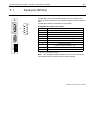
Amplifier plugin units . . . . . . . . . . . . . . . . . . . . . . . . . . . . . . . . . . . . . . . . . . . . . . . . . . .
H
Index
DMP40, DMP40S2
E47
E48
E50
E51
G3
A1
A
Introduction
DMP40, DMP40S2
A2
DMP40, DMP40S2
Introduction Ý Safety instructions
1
A3
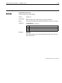
Safety instructions
Use as prescribed
The precision measuring amplifier is to be used exclusively for measurement tasks and directly related control
tasks. Any other use is deemed to be use not as prescribed.
In the interests of safety the instrument should be operated only as specified in the User Manual. It is also essential
to observe the statutory and safety provisions relevant to the particular application. The same applies to the use of
accessories.
General dangers in nonobservance of the safety instructions
The precision measuring amplifier corresponds to the state of the art and is safe to operate. The instrument can
give rise to residual danger if improperly installed and operated by untrained personnel.
Any person charged with installation, commissioning, maintenance or repair of the instrument must have read and
understood the User Manual and in particular the technical safety instructions.
Residual dangers
The performance and list of components supplied with the measuring amplifier cover only part of the scope of
measurement technology. In addition, equipment planners, installers and operators should plan, implement and be
responsible for the technical safety aspects of measurement equipment in such a way as to minimise residual
dangers. All existing regulations must be complied with. Attention must be drawn to residual dangers associated
with measuring equipment.
After settingup and passwordprotected activities, ensure that any controllers that may be connected are in a safe
status, until the switching behaviour of the measuring amplifier has been tested.
DMP40, DMP40S2
A4
Introduction Ý Safety instructions
Any risk of remaining dangers when working with the amplifier system is pointed out in this introduction by means
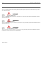
of the following symbols:
Symbol:
DANGER
Meaning:
Maximum danger level
Warns of a decidedly dangerous situation in which failure to comply with safety requirements will lead to death or
serious physical injury.
Symbol:
WARNING
Meaning:
Dangerous situation
Warns of a potentially dangerous situation in which failure to comply with safety requirements can lead to death or
serious physical injury.
Symbol:
CAUTION
Meaning:
Possibly dangerous situation
Warns of a possibly dangerous situation in which failure to comply with safety requirements could cause damage
to property or result in some kind of minor physical injury.
DMP40, DMP40S2
Introduction Ý Safety instructions
A5
Symbol:
Meaning: CE mark
The CE mark enables the manufacturer to guarantee that the product complies with the requirements of the relev
ant EC directives (the declaration of conformity is available at http://www.hbm.com/HBMdoc).
Working safely
Faultmessages must only be acknowledged if the cause of the fault has been eliminated and no further danger
exists.
Conversions and modifications
No modifications may be made to the measuring amplifier from the structural or safetyengineering point of view
without our express agreement. Any modification precludes liability on our part for any resulting damage.
In particular, all repairs and soldering work on motherboards (replacement of components other than EPROMs) are
prohibited. When replacing complete modules only original HBM parts may be used.
Qualified personnel
are persons who are entrusted with the installation, assembly, commissioning and operation of the product and who
possess the appropriate professional, trade or craft qualifications.
This instrument is to be installed and used only by qualified personnel in strict accordance with the technical data
and the safety rules and regulations mentioned. When using the amplifier it is also essential to comply with the stat
utory and safety regulations relevant to the particular application. The same applies to the use of accessories.
Maintenance and repair work on an open amplifier with the power on may only be carried out by a trained person
who is fully aware of the attendant risks.
DMP40, DMP40S2
A6
Introduction Ý Safety instructions
Safety requirements
Find out before commissioning whether the circuit being used is adequately protected.
The mains plug must only be inserted into a socket with a protection switch (Protection Class I). Connecting elec
trical amplifiers to low voltage: connect to extralow safety voltage only (safety transformer in accordance with
DINVDE0551/EN60742).
Before opening the amplifier make sure that it is off by withdrawing the mains plug from the socket.
Never pull the mains plug from the socket by the mains cable.
Do not operate the amplifier if the mains cable is damaged.
If a connection board is withdrawn, the plugin unit must be closed off with a blanking plate.
Builtin equipment should be operated only when installed in the housing provided.
The amplifier complies with the safety requirements of DIN EN 61010, Part 1 (VDE 0411, Part 1); Protection
ClassI.
To ensure sufficient electromagnetic immunity, it is essential to use Greenline shielding only (see HBM brochure
"Greenline shielding design"; internet download http://www.hbm.com/Greenline).
DMP40, DMP40S2
Introduction ➝ Notes on the documentation
2
A7
Notes on the documentation
The complete documentation on the precision measuring amplifier consists of the following publications:
The Operating Manual, (Part 1)
explains how to operate the amplifier manually and use it to take measurements.
The publication Operation with computer or terminal, (Part 2)
shows you how to program and measure using a computer or terminal.
This manual contains all the information you need to operate the DMP.
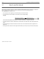
There are several guidelines to help you:
•
The header shows you which chapter or sub−section you are currently reading.
Example:
Connecting up ➝ Mains connection
C12
•
The page numbering consists of a capital letter (corresponding to the chapter heading) and a number.
•
Chapter D Functions and symbols on the DMP explains the display and the control keys
•
Chapter F Menu structure gives an overview of the selection and setup windows
DMP40, DMP40S2
Introduction ➝ Mechanical structure
A8
3
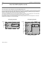
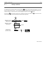
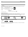
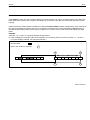
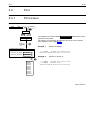
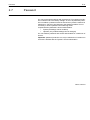
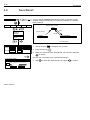
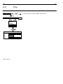
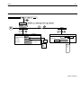
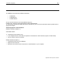
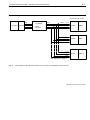
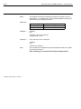
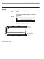
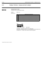
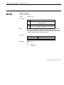
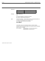
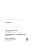
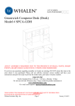
How the DMP amplifier works
This section gives a clear explanation of how the DMP amplifier works.
You can connect as many as eight sequentially selectable channels to the DMP40. Connected transducers (operat
ing on the SG principle) are excited with a 225Hz carrier frequency. Since all the transducers are connected to the
excitation voltage at the same time and are therefore constantly "warmed up", as soon as you switch to the next
channel you can begin taking measurements with complete accuracy.
The alternative DMP40S2 version has two amplifiers operating in parallel, each with eight ports. This means that
two measured values can be displayed simultaneously from a total of 16 channels.
It is possible to display not only the SG signal, but also auxiliary quantities such as the temperature, current and
resistance of the channels or an external voltage.
Auxiliary signal (external voltage,
ext. resistance, ext.temperature)
Channels
1.1
1.2
1.3
1.4
1.5
1.6
1.7
1.8
DMP40
24°C
Auxiliary signal (external voltage,
ext. resistance, ext.temperature)
Channels
1.1
1.2
DMP40S2
1.3
1.4
1.5
1.6
1.7
1.8
2.1
2.2
2.3
2.4
2.5
2.6
2.7
2.8
Auxiliary signal (external voltage,
ext. resistance, ext.temperature)
DMP40, DMP40S2
Introduction ➝ Mechanical structure
4
A9
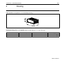
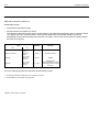
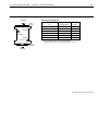
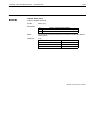
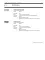
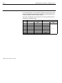
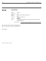
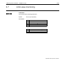
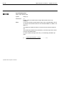
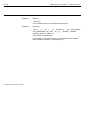
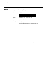
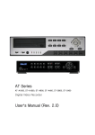
Housing
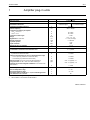
DMP amplifiers are supplied in a 19 inch desktop housing.
h
w
d
Desktop housing with 1 or 2 amplifiers (wā xā hā xā d): 458mmx171mmx367mm
Alternative version
Number of amplifiers
Max. number of channels
Power supply
DMP40
DMP40S2
1
8
230V/115V
2
16
230V/115V
DMP40, DMP40S2
Introduction ➝ Mechanical structure
A10
5
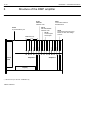
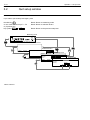
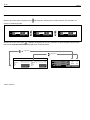
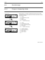
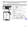
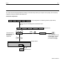
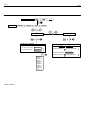
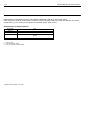
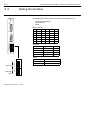
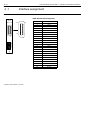
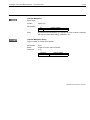
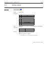
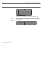
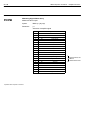
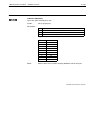
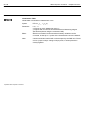
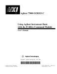
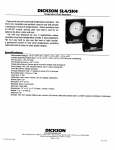
Structure of the DMP amplifier
AP41
Connection board for
SG transducer
PI 12*)
IEEE488
Interface card
CP 12
RS−232/422/485
interface card
SY02
Synchronization port
DMP40S2 only
Power
pack
Amplifier 2
Display
*)
With devices up to IdentNo. 122820045 only.
DMP40, DMP40S2
AP 42
Control inputs
and outputs
Amplifier 1
AP40
Connection board for Pt100,
Pt500, Pt1000, DC voltage
sources
Introduction ➝ Mechanical structure
6
A11
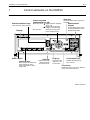
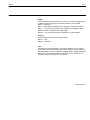
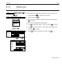
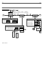
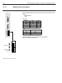
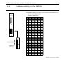
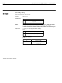
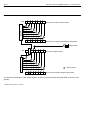
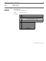
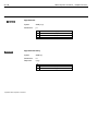
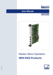
Back of the amplifier, port jacks
RS232C interface
Synchronization
Earthing switch
RS422/485 interface
AP42
Transducer ports
Channels 2.1...2.8
(DMP40S2 only)
Transducer ports
Channels 1.1...1.8
Outputs
Amplifier 1
SY 02
AP42
CP12
IEEE488 interface*)
IdentNo.
Outputs
Amplifier 2
Blanking plate
Mains
connection
Chassis ground
*)
With devices up to IdentNo. 122820045 only.
DMP40, DMP40S2
Introduction ➝ Mechanical structure
A12
7
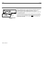
Conditions on site
CAUTION
•
Protect the amplifier from humidity or atmospheric influences such as rain, snow and so on.
•
Please ensure that the ventilation openings in the side and the power pack fan vents in the back of the amplifier
are not covered up.
DMP40, DMP40S2
Introduction ➝ Mechanical structure
8
A13
Maintenance and cleaning
The precision amplifiers are maintenancefree. Please note the following points when cleaning the housing:
•
Remove the power plug from the socket before cleaning.
•
Clean the housing with a soft, damp (not wet) cloth. Never use solvents, since these can damage the display
field as well as the makings and labeling on the front panel.
•
Make sure that no liquids find their way into the amplifier or its connection ports in the course of cleaning.
DMP40, DMP40S2
A14
DMP40, DMP40S2
Introduction ➝ Mechanical structure
B1
B
Connecting up
DMP40, DMP40S2
B2
DMP40, DMP40S2
Connecting up ➝ Mains connection
1
B3
Mains connection
The NT010 power pack is designed for 230V/115V connection as well as for the maximum configuration with 2
amplifiers. Adaptation to the mains supply voltage (115V/230V) is automatic. The fan on the power pack is tem
peraturecontrolled and is automatically switched on only when needed.
The power pack is protected by an internal 3.15 A/T heatcoil fuse.
CAUTION
The powerpack fuse must only be changed by the manufacturer’s service personnel!
Earthing switch
In factory setup (
) the earthing switch connects zero operating voltage to the protection circuit. If external
devices (transducers, computers) already make this link, giving rise to earthcircuits (humpickup), the earthing
switch should be opened ( ).
DMP40, DMP40S2
Connecting up ➝ Transducer port
B4
2
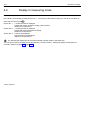
Connecting transducers
2.1
Possible connections
You can connect SG transducers to the DMP amplifier in a fullbridge network. In addition you can connect one
Pt100, PT500, Pt1000 thermistor or one DC voltage source ("10V) via the AP40 connection board.
2.2
Type of connection
Connect SG transducers in sixwire mode.
DMP40, DMP40S2
Connecting up ➝ Transducer port
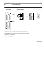
2.3
B5
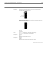
SG full bridges
Terminal plate
Pin assignment
Connection diagram
Input
wh
bk
LEDs
2
bu
rd
1
4
3
ye
gn
gy
Measuring signal (+)
8
Excitation voltage (−)
5
Excitation voltage (+)
6
Measuring signal (−)
15
Cable shielding 1)
Hsg.
Sensor circuit (+)
13
Sensor circuit (−)
12
1
9
8
15
LEDs
Wiring colours: wh= white; bk= black; bu= blue; rd= red; ye= yellow; gn= green; gy= grey
The LEDs above the port jacks indicate the operating status of the channel:
LED on (green) = channel active
LED off = channel inactive
DMP40, DMP40S2
Connecting up ➝ Transducer port
B6
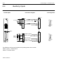
2.4
Auxiliary inputs
Terminal plate
Connection diagram
Pin assignment
Input
(+)
U=±10V
Zero operating voltage
(−)
Cable shielding
8
6
1
9
15
Hsg.
8
15
LED
Excitation voltage
Pt100
Pt500
Pt1000
Sensor circuit
Cable shielding
Sensor circuit
Excitation voltage
The LED above the port jack indicates the operating status of the channel:
LED on (green) = channel active
LED off = channel inactive
DMP40, DMP40S2
5
1
9
12
Hsg.
13
6
8
15
Connecting up → Synchronisation
3
B7
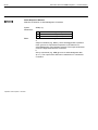
Synchronization
Synchronization prevents beat interference due to carrierfrequency
differences between several DMP amplifiers.
SY 02
All the amplifiers within a device are basically synchronized.
We recommend synchronizing the devices if:
SYNCHR.
MASTER
D
Switch
D the transducer cables of several devices are laid sidebyside
D the channels are unshielded and close together
D
SLAVE
Synchronization jack
Synchronizing several devices
You can synchronize any number of devices over the synchronization
jacks. The synchronization jacks have the same features, so it is
equally valid which of the two you use as input or output. Set the switch
on one device to MASTER, and on all the others to SLAVE.
Use synchronization cable Kab251−0,5 (accessories).
Synchronization jack
DMP40, DMP40S2
Connecting up ➝ Outputs and remotes
B8
4
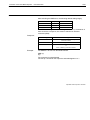
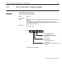
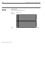
Inputs and outputs; remotes
On the back of the desktop housing are the AP42 connection boards for connecting output and control signals.
These connection boards have a 25pin jack labelled OUTPUT.
The control I/Os are galvanically isolated by optical coupler.
Pin assignment of the AP42*):
1
14
25
13
OUTPUT
1
2
3
4
5
6
7
8
9
10
11
12
13
14
15
16
17
18
19
20
21
22
23
24
25
*)
DMP40, DMP40S2
Control input 1 (ACAL)
Control input 2 (TARE)
Ground (control inputs 3+4)
Control input 5 (CPV 1)
Control input 6 (HLD 1)
Ground (control inputs 7+8)
24V (limit value 1+2)
Ground (limit value 1+2)
24V (limit value 3+4)
Ground (limit value 3+4)
Current output Ia1
not in use
not in use
Ground (control inputs 1+2)
Control input 3 (RNGE)
Control input 4 (FREQ)
Ground (control inputs 5+6)
Control input 7 (CPV 2)
Control input 8 (HLD 2)
Limit value output 1
Limit value output 2
Limit value output 3
Limit value output 4
Warning
Analog ground
The signals for control inputs are freely definable (factory setup is the specified
default).
Connecting up ➝ Outputs and remotes
B9
Control inputs:
Function
Level 0V
Level 24V
ACAL
Autocal ON
Autocal OFF
TARA
Taring is triggered by a transition from 0V to 24V
RNGE
Scaling mV/V
FREQ
Cutoff frequency 1
Cutoff frequency 2
CPV1/2
Peak values 1 and 2 are stored
Peak values 1 and 2 are replaced
by current value
HLD1/2
Peak stores 1 and 2 not frozen
Contents of peak stores 1 and 2 frozen
ZERO
Userdefined scaling
Zero balancing triggered by transition from 0V to 24V
REMT
Remote control contacts inactive
SHNT
Shunt off (XM001)
Remote control contacts active
Shunt on (XM001)
PRNT
Print enabling takes channel
into account
Print enabling does not take channel
into account
CAL
Input is switched to the measuring signal
Input is switched to
internal calibration source
ZERO
Input is switched to the measuring signal
Input is switched to the zero signal
Control outputs:
Function
Level 0V
Level 24V
Limit val.
Limit switches OFF
Limit switches ON
Warning
Device not ready or error (e.g. overload)
No error
DMP40, DMP40S2
Connecting up ➝ Outputs and remotes
B10
Circuit diagram of control outputs:
Limit value outputs 1 ... 4 and Warning
External
AP42
+24V
+
−
0V
The voltage on output is some 0.5...1V lower than the externally connected supply voltage. Maximum current is
dependent on the loadcarrying capacity of the external supply voltage, but is not to exceed 0.5A.
Circuit diagram of the control inputs:
Control inputs 1 ... 8
External
AP42
2.5k
+24V
approx.
12mA
5.6V
5k
+
36V
−
0V
DMP40, DMP40S2
C1
C
Commissioning
DMP40, DMP40S2
C2
DMP40, DMP40S2
Commissioning ➝ Switching on
1
C3
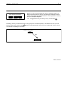
Commissioning
This chapter shows the steps you need to take, in order to make your
measuring system (measuring amplifier and transducer) ready for use.
After connecting the transducer and running the initial commissioning,
you are in a position to get acquainted with the other functions and fa
cilities of the precision measuring amplifier.
•
•
•
•
Unpack the DMP.
Check the DMP for damage.
Is the delivery complete?
Compare the contents of packages with the enclosed documenta
tion list. Is the documentation complete?
DMP40, DMP40S2
Commissioning ➝ Switching on
C4
2
Switch on
This chapter shows the steps you need to take, in order to make your
measuring system (measuring amplifier and transducer) ready for use.
After connecting the transducer and running the initial commissioning,
you are in a position to get acquainted with the other functions and fa
cilities of the precision measuring amplifier.
•
•
•
•
•
•
Switch on
•
DMP40 Initializing
0%
100%
•
•
Unpack the DMP.
Check the DMP for damage.
Is the delivery complete?
Compare the contents of packages with the enclosed documenta
tion list. Is the documentation complete?
Please note the safety instructions in chapter 1!
Connect your transducer to the jack provided for the purpose on the
connection board (named "Input"). If you use a cable that you have
made up yourself, please note the pin assignment for your trans
ducer in
chapterB.
Connect the DMP to the mains supply with the mains cable
provided.
The power pack for the DMP amplifier is designed for 230V or
115V connection. Adaptation to the existing mains supply voltage is
automatic.
Switch on the DMP with the POWER button on the front panel of
the amplifier (after some 10 seconds the opening display appears).
The DMP is initialised and the components present are detected.
In no transducer is connected, an overflow is displayed!
After the opening display has appeared, a standard measured value
display of the "1 value" type appears (factory setup). When you press
the
shift key you access the setup mode, where you can config
ure the channels, amplifiers, display, print options and system.
DMP40, DMP40S2
Commissioning ➝ Switching on
3
C5
Choosing dialog language
We recommend that you only set up the dialog language of you want to use a language other than English.
Check
Channel
Amplifier
Acal
Display
Print
System
Fkeys
Password
Language
Save/Recall
Time
Version
LANGUAGE
Language:
English↓
Deutsch
English
DMP40, DMP40S2
C6
DMP40, DMP40S2
Commissioning ➝ Switching on
D1
D
Functions and symbols on the DMP
DMP40, DMP40S2
D2
DMP40, DMP40S2
D3
Operation Ý Control elements
1
Control elements on the DMP40
Cursor keys and
confirmation key (
Channel selection keys
Measuring mode:
They select the active channel
Display
Setup mode:
Power switch
Function keys
Have an effect in measuring
mode and setup mode;
freely assignable for meas
uring mode
Clear key
Clears the whole of the entry in the
edit fields
)
Alphanumeric
keypad
Signal selection (absolute,
gross, net)
Display mode selection
(single or multichannel)
Moves you to the selec
tion and setup menus
Shift key
Switches between
measuring mode
and setup mode.
For inputting figures, letters
or special characters in the
displayed edit fields
Help key
Confirmation key
Activates online
help for the act
ive functions.
Enables the settings you
have entered
Cancel key
Resets last entry in menus or selection
boxes and closes help texts.
DMP40, DMP40S2
D4
Operation Ý Control elements
You adjust all the settings for your DMP amplifier with the control keys on the front panel. Not all keys have an ef
fect in both operating modes (measuring mode/setup mode).
Keys inside a green border (on the front panel) affect the current display in measuring mode. Function keys F1...F5
also work in setup mode, but they have a different effect.
Keys with a black border are those that only work in setup mode (other than the cursor keys). The
key has a
special purpose. Pressing this shift key takes you from one operating mode to the other, i.e. from measuring mode
to setup mode and viceversa.
Control keys for measuring mode
Green border
DMP40, DMP40S2
Control keys for setup mode
Black border
D5
Operation Ý Display
2
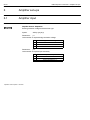
Display
2.1
The first display
After switching on the mains supply (after about 10 seconds) the initial
izing of the DMP40 is shown on the display by a horizontal bar. You are
also given information on the current software version.
After the opening display has appeared, a standard measured value
display of the "1 value" display format appears (factory setup). By
DMP40 Initalizing
0%
100%
you shift to setup, where you can configure
pressing the shift key
the system, the display, the amplifier, print options and the channel set
tings. Firstly, we recommend you set up the language, if you want
something other than German (see chapter 3).
DMP40, DMP40S2
D6
Operation Ý Display
2.2
Display in measuring mode
In the factory, three display formats (Screen No.1 ... Screen No.3) are defined, which you can call up one after an
:
other with the cursor keys
Screen No. 1: 1 measured value is displayed
Header with range, excitation voltage, channel name
Status line is switched on
Screen No. 2: 1 measured value is displayed
Header with minimum/maximum display
Status line is switched on
Screen No. 3: 2 values are displayed
Channel names are displayed
Status line is switched on
On changing the display format, the screen number is briefly shown in the status line.
You can define up to ten display formats and allocate a "Screen number". Setting the display format options is
covered in detail in Chapter 2.4, Page E27.
DMP40, DMP40S2
D7
Operation Ý Display
Which keys affect the display?
With
•
Cursor keys
retrieve the stored display format; symbol
•
Cursor keys
change the signal type (gross, net, absolute); symbol
•
Channel selection keys
•
•
Shift key
.
.
select the required channel.
change from measuring mode to setup mode and viceversa.
Function key F1 − F5 trigger the assigned function (e.g. tare, calibrate, etc.). Function key F4 as set up in the
factory switches between the unscaled value (Abs; mV/V) and the scaling in the physical unit.
DMP40, DMP40S2
D8
Operation Ý Display
Display of screen type "1 measured value"
channel name (freely selectable)
Excitation voltage
or measured value auxiliary channel
Measured value
Range
Unit
output signal
(absolute,
gross,
net)
Header
Status line
F key assignment
Meas.
Number of
channel selec
ted
Acal OFF
Check
Activation message
Display of "2 values" screen type
Channel name
(freely selectable)
Measured value
Meas. value line 1
Unit
Output signal
Absolute
Gross
Net
Number of chan
nels selected
Meas. value line 2
Status line
F key assignment
Meas.
Acal OFF
Check
Activation message
DMP40, DMP40S2
D9
Operation Ý Display
Signal type in the display
In the factory setup, you can display the absolute, gross and net signal for each channel one after another (cursor
keys
).
Example:
Userdefined scaling
Absolute
Zero value=0.5mV/V
Gross
0
0.5
Net
Menu
Tarevalue
Zerovalue
Tare value=0.25mV/V
1.0
mV/V
1.5
0.75 (relative to zero value 0.25mV/V)
For this example, the following values appear in the display:
Absolute
1.5mV/V
Gross
1.0mV/V
Net
0.75mV/V
DMP40, DMP40S2
D10
Operation Ý Display
Status line
The status line keeps you informed of the current status of the measuring amplifier:
Status line
Meas.
Acal OFF
Check
Activation message
Measure,
Zero,
Calibrate
status of amplifier input ("Control" function key)
Filter selected ("Filter" function key)
Acal ON
Automatic calibration On/Off ("Acal" function key)
Status of limit value switch. If the set "on value" of a limit value switch is exceeded, the switch num
ber will be shown on the display with a white background.
Example: On value of limit value switch 1 is exceeded
Low pass filter is in the transient phase. In this state, the displayed value
is not valid!
In this field, activation or status messages (e.g. clr min/max(clear peak values), calibrate, ...) ap
pear briefly
DMP40, DMP40S2
Operation ➝ Setup mode
3
D11
Setup mode
After switching the DMP amplifier on, "measurement mode" is always selected. By pressing the shift key,
you
switch into setup mode and the selection bar appears at the bottom of the display. The setup facilities of the DMP
amplifier are summarized according to function in the selection bar.
Display in setup mode
Channel
Amplifier
Display
Print
System
Selection bar
Channel
Amplifier
Display
Print
System
Range
Scal./Linear
Zero/Tare
Filter
Min/Max Store
Limit values
Copy
Excitation voltage
Channel select
Remote contacts
Display
Screens
Parameters
Fkeys
Password
Language
Save/Recall
Time
Version
Settings relating to
channels for adaptation
of the transducer.
amplifier setups
Useroriented settings
on the display, such as,
for example preferred
display of measured
values, channel/signal
selection, activation of
header or status line
Print options
Systemrelated set
tings, which are
mostly undertaken
when first put into
operation or on
starting a new
measurement job.
DMP40, DMP40S2
Operation ➝ Setup mode
D12
Switch to the setup dialogue, by pressing the shift key
. A selection bar appears at the bottom of the display
and the function keys underneath it (F1 to F5) are assigned to the various selections (selection level 1).
You can setup your DMP amplifier in different menus which you call up using the selection bar. Depending on the
function, you can call in up to 4 menu levels (selection and setup levels). In the first two level you select topics. You
are in Selection levels. In the next levels, you set specific values or switch functions on and off. You are now in
Setup levels.
Using the help key,
you can call up information in any level on selected subjects.
Example: System password setup
Measuring mode
Selection level 1
Meas.
Check
Acal Off
Acal
Selection bar
Selection level 2
Channel
Amplifier
Pullup menu
Di
Password
Channel
Amplifier
Fkeys
Password
Language
Save/Recall
Time
Version
Setup window
Setup level 1
User:
new
Password:
modify
Access:
Channel
delete
Setup level 2
Define User
Amplifier
Set..
User:
.
Password:
Authority:
Operator
OK
Setup window
DMP40, DMP40S2
Cancel
Operation ➝ Setup mode
3.1
D13
Setup window
The starting point is measuring mode. Press the shift key
. At first, only the selection bar appears. If you now
press one of the function keys F1 − F5, the relevant pullup menu appears above the appropriate subject (in this
example "System"). In the pullup menu, move the highlight using the cursor keys
function keys
or the
to the subject required (here "Language") and press the confirm key
. You are now in the
selected subject. The current setup window can lead to other setup levels.
Selection level 1
Selection bar
Selection level 2
Pullup menu
Setup level 1
Selection window
Channel
Amplifier
Fkeys
Password
Language
Save/Recall
Time
Version
English ↓
Display
Print
System
Highlight
English
English
DMP40, DMP40S2
Operation ➝ Setup mode
D14
3.2
Quit setup window
If you want to quit a setup level again, press
the shift key
or one of the function keys F1 − F5
or (if present) the
key symbol Cancel or OK
Result: Return to measuring mode
Result: Return to selection level 2
Result: Return to the previous setup level
Measuring mode
Meas.
Check
Acal Off
Acal
Selection level 1
Selection level 2
Channel
Amplifier
Password
User:
Channel
Amplifier
Di
Fkeys
Password
Language
Save/Recall
Time
Version
Setup level 1
new
Password:
Access:
Channel
nelete
modify
Setup level 2
Define User
Amplifier
Set..
User:
.
Password:
Authority:
Operator
OK
DMP40, DMP40S2
Cancel
Operation ➝ Setup mode
D15
Save settings permanently?
Yes
No
Cancel
Before you quit a menu window and return to measuring mode, you
always have the option of saving or not saving the settings you have
made or interrupting quit dialogue window. For this purpose, a security
prompt is displayed alongside.
"Yes" is suggested here by the factory setup. Confirm with
.
All settings, which you made before the security prompt are stored temporarily in the RAM as soon as you have
. Data is saved permanently, as soon as you confirm with "Yes" at the se
made a change and confirmed with
curity prompt on quitting setup mode.
Volatile memory (8hrs)
RAM
Save
EEPROM
Permanent save
DMP40, DMP40S2
Operation ➝ Setup mode
D16
3.3
Selection menus
In the first two selection levels, you select subjects. In the first level (menu bar) by pressing the relevant function
key
, in the second level by selecting from the pullup menu with the cursor keys
ing the function keys
or by repeatedly press
.
• Making selections from the selection bar
Channel
Amplifier
Display
Example:
Print
System
The pullup menu appears after pressing the function key.
• Selecting and confirming in the pullup menu
Example:
Fkeys
Password
Language
Save/Recall
Time
Version
The field selected is displayed inversely. Confirm your selection with
. Pullup menus can be scrolled, i.e. hav
ing gone right through the menu, you return to the first selection again. The item last selected with the highlight is
saved.
DMP40, DMP40S2
Operation ➝ Setup mode
3.4
D17
Setup window
Enter the parameters with the setup window in the setup level. Located in the setup windows are dialogue fields,
which can be split up into four different types.
SETUP WINDOW
Activation fields
Dialogue fields
Selection field
Edit field
2.5V
5V ↓↓
1st amplifier: 5V
10V
abs.
gross
net
User:
Button
Cancel
• Switching on or off in activation fields
Example:
abs.
gross
net
The field selected is displayed inversely. Confirm your selection with
tivated"). If the confirm key is pressed again, activation is restored.
• Opening and selecting in selection boxes
Example:
1st amplifier: 5V ↓
1st amplifier:
. A tick appears in the box selected ("ac
2.5V
5V ↓
10V
The field selected is displayed inversely. After pressing the confirm key,
the cursor keys
select and confirm your setting with
fields are indicated by downward pointing arrows↓ .
the selection field opens up. Using
. In the documentation (not on the display), such
DMP40, DMP40S2
Operation ➝ Setup mode
D18
• Edit fields
You can enter numbers or letters in edit fields. In some edit fields, you can only enter numbers (e.g. zero value),
because it would not make sense to enter letters here.
Example:
a) Edit field with no content
User:
The field selected is displayed inversely. Confirm your entries with
Example:
b) Edit field with content
You can
Zero point:
.
0.000
− directly overwrite,
− partially edit
− completely delete with the delete key
an edit field with content.
Inputting numbers and letters
The keys of the alphanumeric input field are assigned 7 times: 1 number, 3 upper case letters, 3 lower case letters.
The first time you press a key, a number appears, then when pressed again letters follow.
When entering consecutive letters that are on the same key, you must press the cursor key
Example for the letter sequence "FE":
1st step
2nd step
4x
The minus sign of the key
• Buttons
Example:
Cancel
3rd step
1x
3x
can also be used as a separator in text fields.
or
change...
The field selected is displayed inversely. Confirm with
which appear after confirming another setup window.
DMP40, DMP40S2
between the letters.
. Three dots (change ...) follow the button designation
E1
E
Setting up the DMP
DMP40, DMP40S2
E2
DMP40, DMP40S2
E3
Settinguptheamplifier
1
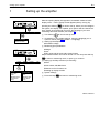
Setting up the amplifier
After the opening display has appeared, a standard measured value
display of the "1 value" display format appears (factory setup). By
Meas.
Acal Off
Check
Acal
Channel
Amplifier
Display
Print
System
pressing the shift key
you shift to setup, where you can configure
the system, the display, the amplifier, print options and the channel set
tings. Firstly, we recommend you set up the language, if you want
something other than German (see chapter 3).
Use shift key
If necessary: in the system settings, set up the language you re
quire for menus (see E47 System→ Language)
Setting up the amplifier:
’Excitation voltage
Measuring point parameters:
’Range
’Unit
’Zero point and fullscale value (Scal./Linear)
Simple measurements can now be carried out. You can press shift key
Excitation voltage
Channel select
Remote contacts
Meas.
Acal Off
Check
to choose setup mode
Acal
to return to measuring mode, or pressto continue.
Channel
Range
Scal./Linear
Zero/Tare
Filter
Min/Max Store
Limit Values
Copy
Amplifier
Display
Range
Scal./Linear
Zero/Tare
Filter
Min/Max Store
Limit Values
Copy
Print
Setting up auxiliary functions (if necessary)
’Filter
’Limit values, Min/Max Store
’Remote control contacts, etc.
’Setting up display formats
System settings
Press shift key
and return to measuring mode
DMP40, DMP40S2
E4
Settinguptheamplifier
Example:
The transducer is a load cell with the following rated data:
Nominal load: 50kg
Sensitivity: 2mV/V
1. Use the measuring point selection keys
to choose the measur
ing point you require.
2. Use the shift key
3. Press function key
tion voltage". Press
to change to setup mode.
Amplifier" and use
to select "Excita
to open the selection box.
4. Select 5V from the selection box and confirm with
5. Use
.
to change to the "Channel" popup menu.
6. Press the confirmation key
to open the "Range" setup window.
7. Press the confirmation key
to open the "Range:" selection box.
8. Select 2.5mV/V from the selection box and confirm with
9. Use
DMP40, DMP40S2
to change to the "Channel" popup menu.
.
E5
Settinguptheamplifier
10. Select "Scal./Linear" with the cursor key
and confirm with
.
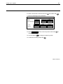
11. Enter the following into the edit fields:
SCALING/LINEARIZATION
CHANNEL 1.1
Step:
1
1
Save
Num.precision:
3
3
Restore
kg
mV/V
1st pt.
0.000
0.000
measure
2nd pt.
50.000...
2.000
measure
Save
12. Select
with the cursor keys and confirm with
enable the settings.
13. Use the shift key
to
to change to measuring mode.
14. Confirm the security prompt with
.
DMP40, DMP40S2
E6
Range
1.1
Measuring range
Check
Acal
Channel
Amplifier
The choice of measuring range is dependent on the excitation voltage
selected.
Display
Print
System
Range
Scal./Linear
Zero/Tare
Filter
Min/Max Store
Limit Values
Copy
RANGE
*)
Range:
DMP40, DMP40S2
6wire ↓
5mV/V ↓
2.5mV/V
5mV/V
10mV/V
2.5
5*)
10
Selectable range (mV/V)
2,5
5
10
2,5
5
2,5*)
Factory settings
Notes:
• The maximum accuracy specified in the Technical Data is only
reached with the settings: Excitation voltage=10V and
Range=2.5mV/V.
CHANNEL 1.1
The excitation voltage is set to 2.5V
Excitation voltage (V)
4wire
6wire
E7
Range
1.2
Check
Scaling and linearization
You can assign two values to each function in this setup window (with
the exception of the unit). The value on the left refers to userdefined
scaling, and the one on the right refers to scaling in mV/V. With the
"measure" button you adopt only values in mV/V (righthand edit field).
Acal
Channel
Save
Range
Scal./Linear
Zero/Tare
Filter
MIn/Max Store
Limit Values
Copy
Restore
measure
SCALING/LINEARIZATION
Step:
1↓
Num.precision: 0...
Unit:
ppm ↓
CHANNEL 1.1
1↓
Save
0 ...
Restore
mV/V
0.000000...
0.000000...
measure
2nd pt. 0.000000...
0.000000...
measure
3rd pt.
0.000000...
0.000000...
measure
4th pt.
0.000000...
0.000000...
measure
5th pt.
0.000000...
0.000000...
measure
6th pt.
0.000000...
0.000000...
measure
7th pt.
0.000000...
0.000000...
measure
8th pt.
0.000000...
0.000000...
measure
9th pt.
0.000000...
0.000000...
measure
0.000000...
0.000000...
measure
0.000000...
0.000000...
measure
1st pt.
10th pt.
11th pt.
Saves all changes immediately.
Resets changes and adopts the values from the last Scal/
Lin. points.
Accepts the instantaneous measured value (in mV/V) into
the edit field.
Step
Step lets you define the display step size. The step width refers to the
last decimal place.
Example: End value 20kg
Decimal places 1 (20.0kg)
Step 1 means the display is in steps of 100g
Step 5 means the display is in steps of 500g
Decimal places 3 (20.000kg)
Step 1 means the display is in steps of 1g
Step 5 means the display is in steps of 5g
Num.precision
Number of decimal places in the display.
DMP40, DMP40S2
E8
Range
SCALING/LINEARIZATION
Step:
1↓
Num.precision: 0...
Unit:
ppm ↓
CHANNEL 1.1
1↓
Save
0 ...
Restore
mV/V
1st pt.
0.000000...
0.000000...
measure
2nd pt.
0.000000...
0.000000...
measure
3rd pt.
0.000000...
0.000000...
measure
4th pt.
0.000000...
0.000000...
measure
5th pt.
0.000000...
0.000000...
measure
6th pt.
0.000000...
0.000000...
measure
7th pt.
0.000000...
0.000000...
measure
8th pt.
0.000000...
0.000000...
measure
9th pt.
0.000000...
0.000000...
measure
0.000000...
0.000000...
measure
0.000000...
0.000000...
measure
10th pt.
11th pt.
Unit
Required unit in the display (e.g. ppm).
1st pt. ... 11th pt.
The edit field "1st pt. to 11th pt." is used for the linearization of a trans
ducer curve.
Display errors arising from a nonlinear characteristic curve can be
compensated by this means. Basically, when the characteristic curves
are sharply nonlinear, more points must be provided on the curve in
order to ensure shorter straightline sections.
Linearization with 2 points
kg
Linearization with 5 points
5
2
4
3
1
mV/V
1
2
Characteristic curve of the transducer
Linearized characteristic curve
Enter the points of the curve in ascending order (in the mathematically
positive direction).
DMP40, DMP40S2
E9
Settingzero/taring
1.3
Check
Setting zero/taring
Zero value
Edit field for the zero value.
Acal
Tare value
Edit field for the tare value..
Channel
Zero
Transfers the instantaneous measured zero value (in
mV/V) into the edit field.
Range
Scal./Linear
Zero/Tare
Filter
Min/Max Store
Limit Values
Copy
ZERO AND TARE VALUES
Tare
Transfers the instantaneous measured tare value (in
mV/V) into the edit field.
The concepts "zero value" and "tare value" are explained in chapter
2.2, page D9 with an example.
CHANNEL 1.1
Zero value: 0.000000...
mV/V
Zero
Tare value: 0.000000...
mV/V
Tare
DMP40, DMP40S2
E10
Filter
1.4
Low pass filter
Step response
Butterworth
Step response
Bessel
DMP40, DMP40S2
Low pass filters are used to suppress undesirable highfrequency inter
ference above a certain cutoff frequency.
Two different cutoff frequencies are provided for a channel, and you can
use whichever you choose (fc1, fc2). You can set up the cutoff frequen
cies at specified levels.
Amplitude response, transit time and step response are dependent on
the filter characteristics. You can choose between the Butterworth char
acteristic and the Bessel characteristic.
The Butterworth characteristic exhibits a linear amplitude response
which falls away steeply above the cutoff frequency. An overshoot of
some 10% occurs.
The Bessel characteristic exhibits a step response with very little (<1%)
or no overshoot. The amplitude response falls away less steeply.
Each amplifier has two defaults (Lowpass 1, Lowpass 2), and only one
filter is active.
E11
Filter
Check
Channel
Acal
Amplifier
Display
Print
The following example explains the settings:
Weights are to be determined with a balance. The balance consists of a
platform which tends to vibrate at 12Hz. Disturing frequencies higher
than 11Hz are to be filtered out.
1. Use shift key
Range
Scal./Linear
Zero/Tare
Filter
Min/Max Store
Limit Values
Copy
2. Press
to change to setup mode.
.
to
3. Make your choice from the "Filter" pullup menu and press
confirm.
4. Choose "Butterworth" from the "Filter 1" selection box and press
to confirm.
CHANNEL 1.1
5. Choose "11.0Hz" from the "Filter 1" selection box and press
confirm.
Filter 13dB cutoff frequency:
0.02↓ Hz Bessel↓
6. When you want to return to measuring mode, press shift key
Filter 23dB cutoff frequency:
10↓
FILTERS
Hz Butterw↓
and confirm the security prompt with
to
.
Bessel
Butterworth
0.03
0.05
0.1
0.22
0.45
0.90
1.7
1.1
1.6
2.3
3.2
4.6
6.4
8.7
11 0
DMP40, DMP40S2
E12
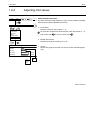
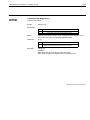
1.4.1
Filter
Switching filters
You can switch between the preset filters:
−
−
−
DMP40, DMP40S2
In measuring mode via the function key (factory setup
, 2nd
level).
Via the remote control contacts, when remote control is on.
With the command "AFS" (Computer control, Part 2).
E13
Min/Maxstore
1.5
Min / Max store
measured
Min/Max
You can use the ’Min/Max’ function to record and save individually oc
curring signal peaks and minimum/maximum signal amplitudes. Each
amplifier contains two Min / Max stores.
With these you can save:
maxima
minima or
peaktopeak amplitudes
Gros
Net
Min / Max storage
Display
Peak to peak
(Envelope)
In the case of rapid dynamic signals, you must take into account that
peak values are defined in the time slot of the currently selected filter
(1.2Hz − 75Hz).
DMP40, DMP40S2
E14
Min/Maxstore
1.5.1
Check
Channel
Deactivate / delete Min/Max store
In the factory setup, min/max stores are active (Enable min/max store
"Yes").
Acal
Amplifier
Display
Deactivate Min/Max storage
Print
1. Use the shift key
Range
Scal./Linear
Zero/Tare
Filter
Min/Max Store
Limit Values
Copy
2. Press
to change to setup mode.
.
3. Make your selection from the "Min/Max Store" pullup menu and
press
to confirm.
4. Select "Enable min/max store" "No" from the selection field and
press
to confirm.
5. Use the function key
MIN / MAX STORAGE
CHANNEL 1.1
shift key
to switch to measuring mode.
To save space, min/max stores are abbreviated to Store1 and Store2 in
other setup windows.
Enable min/max store: Yes↓
Store 1 function:
Maximum↓
Store 1 envelope:
On↓
Store 2 function:
Minimum↓
Store 2 envelope:
On↓
0 ...
0 ...
to return to the pullup menu or use the
ms
Clear Min / Max store
You have three options for clearing the min/max store:
ms
1. Using a function key (factory setup
On
Off
DMP40, DMP40S2
Maximum
Minimum
Peak to peak
,/2ndlevel).
2. Using remote contacts CPV1/CPV2, if the device is set up for re
mote control.
3. Using a computer with the command "CPV".
E15
Min/Maxstore
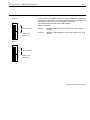
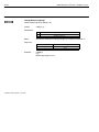
1.5.2
Controlling Min / Max storage
Two remote contacts have an influence on min/max storage:
CPV:
is used for deleting the min/max store
HLD: freezes the current content of the store or releases it
You can carry out other functions with these remote control elements,
such as, for example, storing the instantaneous value.
DMP40, DMP40S2
E16
Min/Maxstore
1.5.3
"Peak value" operating mode
Measuring
signal
Memory contents
Vi, Vo
Function
Operating
mode
Run
Min/Max
DMP40, DMP40S2
Hold
t
Run
Instantan
eous
value
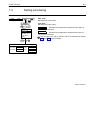
In "Peak value" operating mode, you can save the minimum value, the
maximum value or the peaktopeak value ("Run" function). With the
"Hold" function you can hold the contents of the store:
CPV control circuit
Peak/instantaneous
value
Store1 =AP42, Pin 4
Store2=AP42, Pin 18
Store1=AP42, Pin 5
Store2=AP42, Pin 19
Min/Max:
Memory running in
selected direction
with
24V
0V
Freeze value
any
24V
Function
HLD control circuit
Run/Hold
E17
Min/Maxstore
1.5.4
"Instantaneous value" operating mode
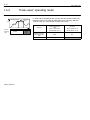
In "Instantaneous value" operating mode, the store is continuously up
dated ("Run" function). With the "Hold" function you can hold the con
tents of the store: You switch the min/max store to instantaneous value
operating mode using the remote contacts.
Measuring signal
Vi, Vo
Memory
contents
t
Function
Operating
mode
Run
Hold
Instantaneous
value
Function
Run
Control circuit
Peak/instantaneous value
Store1 =AP42, Pin 4
Store2=AP42, Pin18
Control circuit
Run/Hold
Store1 =AP42, Pin 5
Store2=AP42, Pin 19
Instantaneous value:
memory running in
either direction with
0V
0V
Freeze value
any
24V
DMP40, DMP40S2
E18
Min/Maxstore
1.5.5
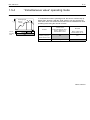
Envelope operating mode
Output signal
100%
30%
Input signal
Time constant
Time constant: OK
Time constant: too large
Time constant: too small
DMP40, DMP40S2
Min/max stores can also be used for displaying envelopes. The envel
ope function is particularly suitable for the measurement of amplitude
modulated oscillations. By entering a time constant, you define how
quickly the min/max store discharges to 30% of the peak value, if this is
no longer present at the input to the store. The choice of time constant
depends on the basic oscillation frequency f0 and the modulation fre
quency. In general terms, you get usable envelopes with a time con
stant which is approximately 10 times the basic frequency period (t= 10
/ f0).
E19
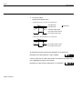
Limitvalues
1.6
Meas.
Check
Limit values
Acal off
Acal
Limit value display
For the assessment of mass or weight tolerances, or when monitoring
forces, pressures, etc., it is often necessary to keep within certain
planned or limit values. Each amplifier has four limit values available for
this purpose (as delivered, these are switched on).
You can preset the limitvalue monitoring level. You also select the
operating direction and hysteresis. The hysteresis value prevents
"fluttering" of the limitvalue switch when the switching threshold is
reached. The hysteresis is derived from the difference between the on
and off values.
Please note when working with limit values:
− The measuring signal must be present for at least 1ms. The
measurement voltage delivered by the amplifier is compared
internally with the reference voltage. If the measurement voltage
reaches or exceeds the set reference voltage, it triggers the
associated logic output.
The factory setting is a hysteresis of 1% (limit values 1 and 2 below the
On value, limit values 3 and 4 above the On value).
DMP40, DMP40S2
E20
Limitswitches
1.6.1
Check
Deactivate limit value switches
Limit values are enabled in the factory setting (Enable limit switch
"Yes").
Acal
Channel
Amplifier
Deactivate limit value switches
Display
Prin
1. Use the shift key
Range
Scal./Linear
Zero/Tare
Filter
Min/Max Store
Limit Values
Copy
to change to setup mode.
2. Press function key
.
3. Make your choice from the "Limit values" pullup menu and press
to confirm.
4. Choose "No" from the "Enable limit switch" selection box and press
to confirm.
5. Use the function key
LIMIT VALUE SWITCH 1
1 ..
Limit values
shift key
Enable limit switch No ↓
Source
Gross ↓
prompt with
On value
2.550000 ...
mV/V
Off value
2.525000 ...
mV/V
abs
gross
net
DMP40, DMP40S2
to return to the pullup menu or use the
Channel 1.1
No
Yes
to change to measuring mode (confirm the security
).
E21
Limitvalues
1.6.2
Check
Channel
Adjusting limit values
Setup window Limit values
You must select this setup window on every occasion before activating
the limit value switches (Enable limit switch).
Acal
Amplifier
Display
Prin
•
Limit values
Number of the limit value switch (1...4)
To select the required limit value switches, enter the number (1...4)
Range
Scal./Linear
Zero/Tare
Filter
Min/Max Store
Limit Values
Copy
and confirm with
•
LIMIT VALUE SWITCH 1
1 ..
Limit switches
Channel 1.1
Enable
Source
No ↓
Gross ↓
On value
2.550000 ...
mV/V
Off value
2.525000 ...
mV/V
abs
gross
net
•
or use the cursor keys
.
Enable (limit switch)
Switches limitvalue monitoring on or off
Source
Selects the signal source that you want to monitor (absolute/gross/
net/)
No
Yes
DMP40, DMP40S2
E22
Limitswitches
•
On and off values
Inputting the operate value
a) Switches when the on value is exceeded (E>A)
E
A
On value (E)
Off value (A)
Hysteresis
Amplifier output signal
1
Limit value switch closed
Limit value switch open
0
b) Switches on dropping below the on value (E<A)
A
E
1
0
Limit value switch closed
Limit value switch open
All enabled limit value switches are displayed on the status line.
Example: Limit value switches 1 and 2 enabled
If the On value set for a limit value switch is exceeded, the switch num
ber is highlighted in white on the display.
Example: On value for limit value switch 1 is exceeded
DMP40, DMP40S2
E23
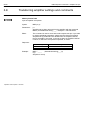
Copy
1.7
Check
Copy
You can use the "Copy" function to send the settings for one channel to
other channels.
Acal
1. Use the shift key
Channel
Amplifier
Display
Prin
2. Press function key
4. Press
press
1.1 ↓
, select the required channel number with
and
to confirm.
to select the key symbol "All" or select from check boxes
5. Use
1...8 those channels (n), deren ) whose settings are to be overwrit
COPY THE CHANNEL SETTINGS
to channels:
.
to
3. Make your choice from the "Copy" pullup menu and press
confirm.
You are now in the setup window "COPY THE CHANNEL SETTINGS".
Range
Scal./Linear
Zero/Tare
Filter
Min/Max Store
Limit Values
Copy
Copy from channel
to change to setup mode.
ten. Confirm with
OK
1. 1 2 3 4 5 6 7 8>
6. Use
.
to select the "OK" button and confirm with
.
all
1.1
1.2
1.3
1.4
.
.
.
DMP40, DMP40S2
E24
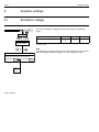
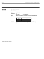
Amplifiersettings
2
Amplifier settings
2.1
Excitation voltage
Check
Acal
mV/V
The chosen excitation voltage can restrict the choice of measuring
range.
Amplifier
Excitation voltage
Channel select
Remote contacts
Attention: Amplifier input range may be effected!
2.5V
5.0V
10.0V
DMP40, DMP40S2
2.5
5*)
10
Selectable range (mV/V)
2.5
5
10
2.5
5
2.5*)
Factory setup
Note:
The maximum accuracy specified in the Technical Data is only reached
with the settings: excitation voltage=10V and range=2.5mV/V.
EXCITATION VOLTAGE
1st amplifier: 5.0V↓
*)
Excitation voltage (V)
2nd amplifier: 5.0V↓
E25
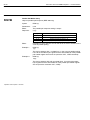
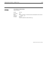
Selectingachannel
2.2
Selecting a channel
In the "Channel select" setup window, you can enable or disable up to 16 channels (DMP40S2 only; otherwise 8
channels) and specify a name of your choice for each channel (max. 10 characters).
In the factory setup, the first digit represents the amplifier and the second digit the channel (2.3 = amplifier 2, chan
nel3).
DMP40, DMP40S2
E26
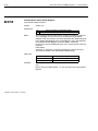
2.3
Remotecontrolcontacts
Remote control contacts
The OUTPUT jack on the AP42 connection board (back of device) has eight remote control contacts. They are
used to initiate or switch on/off certain functions of the DMP amplifier by means of 24V control signals (see also
Chap. 4, page B8). The remote control contacts are only active if remote control is ON (REMT). Assignment of the
remotes can be freely chosen.
DMP40, DMP40S2
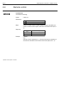
E27
Display
2.4
Display format
Type 1 value
Meas.
Check
Acal Off
Acal
Type 2 values
Meas.
Check
The settings in the setup window Display format affect the appearance of
the signals you can select in the display. Basically you can choose
between three different signals per amplifier (gross, net, absolute
value).
The display status details illustrated left are known as screen types or
simply types, and can be selected in the setup window.
Appearance
• 1 value (with/without status line; with/without header)
• 2 values (with/without status line)
Acal Off
Acal
DMP40, DMP40S2
E28
Display
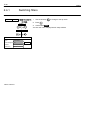
2.4.1
Check
Switching filters
1. Use the shift key
Acal
2. Press
Display
to change to setup mode.
.
3. Confirm with
.
You are now in the "Display format" setup window.
Display
DISPLAY FORMAT
ScreenNo.:
1 ...
Type:
One value ↓
Channels/Signals: all↓
Header:
ext.temperature↓
Status line:
On ↓
DMP40, DMP40S2
one value
selection...
E29
Display
2.4.2
Setup window components
ScreenNo.
You can enter the figures 1...10 in this edit field. This lets you save your
current display settings under a number or recall the factory preset
tings. You can also define the sequence in which the screen types are
selected with the cursor keys
in measuring mode.
Type
With the type you define the number of measuring signals (as a numer
ical value) that can appear simultaneously in the display.
The structure of the "Display format" setup window depends on the
screen type selected. The window mask differs depending on the selec
ted screen type.
Window for type
"1 value"
DISPLAY FORMAT
one value
0 ...
One value ↓
ScreenNo:
Type:
Channels/signals: all ↓
Range/Excitation ↓
Header:
On ↓
Status line:
Window for type
"2 values"
selection...
DISPLAY FORMAT
two values
0 ...
ScreenNo:
Type:
two values ↓
1st value (base):
Channels/Signals:
2nd value:
channel:
all↓
selection...
Channel
0
signal base ↓
Channel name:
On ↓
Status line
On ↓
unit
base ↓
DMP40, DMP40S2
E30
Display
1st value (base)
This appears in first position in the display.
1st value
2nd value
Meas.
Check
Acal Off
Acal
Channels/signals
Here you define which channels will appear with which signals in the
display. You can define your settings for all channels or only for certain
(selected) ones (button selection... ). You can call a maximum of three
signals per channel in sequence (absolute, gross, net).
SELECTION OF CHANNELS / SIGNALS
OK
Cancel
Channel 1.
abs
gross
net
all channels
1 2 3 4 5 6 7 8
all signals
Define...
This button opens a new setup window Selection of channels / sig
nals.
2nd value
It appears in second position in the display.
Channel
There are two ways to enter the channel number. The type of input de
termines how the system relates to the 1st value (base).
Input absolute to base: the value entered is identical to the channel
number, e.g. "1.5" . The measured value and the signal type are dis
played regardless of the base.
DMP40, DMP40S2
E31
Display
Input relative to base: the value entered relates to the base channel (1st value). Channels located to the left of the
base channel are entered with a negative operating sign, and those to the right are entered with a positive operat
ing sign.
Please note that it is not possible to display two channels from the same amplifier simultaneously. This means that
the channel specified for the 2nd value is only accepted if the channel of the second amplifier (DMP40S2 only) or
the base channel itself (relative=0) functions in response to it. If this is not the case, the second display line stays
blank.
Example:
Channels 1.2, 1.3 and 1.4 have been defined as base values.
In order to display the channels of the second amplifier, it only makes sense to input the numbers −2 ...−9 and +7
...+14 in the "Display" edit field. The input was actually 7.
Selected base
Input in the "Channel:" edit field
−9
Amplifier 1
1.1
1.2
1.3
1.4
1.5
−2
2nd amplifier (DMP40S2 only)
1.6
1.7
1.8
Channel:
2.1
7
2.2
2.3
2.4
2.5
2.6
2.7
2.8
14
DMP40, DMP40S2
E32
Display
With the aid of the channel selection keys
all channels, starting from the base channel, are selected in se
quence in measuring mode.
Value 1
Value 2
1.2
2.1
Value 1
Value 2
1.4
2.3
Value 1
Value 2
Meas.
Meas.
Meas.
Check
Check
1.5
2.3
Check
With the aid of the cursor keys
(SIGNAL) all signals set up in the "Selection of channel/signal" setup window
that function with the base value are displayed in measuring mode.
brings about
brings about
SELECTION OF CHANNELS / SIGNALS
Channel 1.
abs
gross
net
DMP40, DMP40S2
1 2 3 4 5 6 7 8
Channel 2.
abs
gross
net
1 2 3 4 5 6 7 8
Meas.
Check
Value 1
abs
1.5
Value 2
gross
2.3
E33
Display
Signal
Choice of signal type (absolute, gross, net). If you want the signal type
to depend on the signal type of the base channel, choose Base,
Base+1 or Base+2.
Base → signal type is identical to the signal type of the base channel.
Base+1 → is moved one position (to the right) in the sequence Abso
lute/Gross/Net in relation to the base signal.
Base+2 → is moved two positions in relation to the base signal
Example:
"Gross" has been chosen as the base signal.
Base+1 = Net
Base+2 = Absolute
Unit
The preferred unit of measure in the display. Besides "mV/V" scaling
and "Udim" userdefined scaling, you can accept the unit of measure of
the base (Base) or invert it (Toggle). Toggling means changing between
base units, e.g. if the base unit is mV/V then the unit "Scaled" is dis
played for the second value and viceversa.
DMP40, DMP40S2
E34
Display
Channel name
Fades the channel name in or out of the display.
Header (1 value)
Fades the header in or out of the display. In the header you have the
option of displaying:
•
•
•
•
•
Min/Max Store (Minimum/Maximum)
Range and excitation voltage
External voltage
External resistance
External temperature
Status line
Fades the status line in or out of the display. The details on the status
line refer to the 1st value.
DMP40, DMP40S2
E35
Print
2.5
Print
2.5.1
Print screen
Check
Acal
mV/V
Print
Screens
Parameters
The settings in the setup window Define print screen define which screen
types are to be printed.
For printing, you can assign two function keys to the "Print" function
(see "System, F keys"; page E37).
Example1:
Printout of "Display"
DEFINE PRINT SCREEN
F−key ’Print_S1’ prints:
Act.screen↓
F−key ’Print_S2’ prints:
Act.screen↓
1.1 1.1−DMP40
15862 ppm Gross 23−Jul−96 11:06:12
Measure Filt: 0.22 Hz Be AutoCal: On LV:1=0,2=0,3=0,4=0
Example2:
Act.screen
Screen 1
Screen 2
Screen 3
Screen 4
Screen 5
Screen 6
Screen 7
Screen 8
Screen 9
Screen 10
Printout of "Screen 2"
1.1 1.1−DMP40
15862 ppm Gross 23−Jul−96 11:05:40
1.1 1.1−DMP40
0.039656 mV/V Abs
Measure Filt: 0.22 Hz Be AutoCal: On LV:1=0,2=0,3=0,4=0
DMP40, DMP40S2
E36
Print
2.5.2
Check
Printout parameters
Acal
mV/V
With the "Printout parameters" function you can print out:
− System parameters
− Amplifier parameters
− Channel parameters
− Display parameters
− Print parameters
Print
Screens
Parameters
Select the parameters you require or enable all parameters with the
all
button
.
The button Print
activates the print run. You can also assign a func
tion key to the "Printout parameters" function (see "System, F keys";
page E37).
PRINTOUT PARAMETERS
Print
all
System parameters 3
Amplifier parameters
3
Example3:
Printout the parameters
1. 1 2 3 4 5 6 7 8
Channel parameters
Display parameters 3
DMP40, DMP40S2
Print parameters
3
System Parameter:
−−−−−−−−−−−−−−−−−
System version : DMP40,P10
Dialog language: English
Time
: 11:00:59
Date
: 23−07−96
User
: HBM
Password
: SESAM
Function keys:
1st level
F1 = Check (zero/cal/measure signal)
One channel
F2 = Autocal (autocalibr. on/off)
One channel
F3 = −>T<− (taring)
One channel
F4 = mV/V (unscaled/scaled)
One channel
F5 = . . . (Next F−level)
E37
Fkeys
2.6
Function keys
2.6.1
Fkeys in measuring mode
Function keys F1...F5 work in measuring mode and in setup mode.
In measuring mode you can make use of a total of 9 functions on three
levels (factory setup):
• F1 Check
• F2 Autocalibration On/Off
• F3 Taring
• F4 Switch range
• F5 . . . (move to next level)
F keys − Level 1
Meas.
Acal Off
Check
F keys − Level 2
Meas.
Acal Off
Check
F keys − Level 3
Meas.
Aux−Chan
Acal Off
P−print
Print−S1
Print−S2
•
•
•
•
•
F1
F2
F3
F4
F5
Check
Autocalibration On/Off
Filter 1/Filter2 Print values
Clear Store
. . . (move to next level)
•
•
•
•
•
F1
F2
F3
F4
F5
Auxiliary channels
Printout parameters
Print screen 1
Print screen 2
...
DMP40, DMP40S2
E38
Meas.
Fkeys
Acal Off
Check
...
The "Taring" function
being defined for all
channels
DMP40, DMP40S2
The key assignment can be freely selected; the allocation shown here
corresponds to the factory settings. In the factory setup, key F5
switches switches to the next appropriate level (...Flevel).
You can extend the effect of the functions to all channels or restrict it to
one (selected) channel.
In measuring mode for all screen types, the bottom line of the display
shows the current key assignment. If you have defined the function for
all channels, this is shown by the symbol . . . in the top righthand
corner of the Fkey field.
E39
Fkeys
Check
Select setup menu
1. Use the shift key
Channel
Amplifier
Display
Print
System
Level
Level 1
1↓
F1: Check (zero/cal/measure signal)↓
F2: Autocal (autocalibr. on/off)↓
F3: −>T<−(taring) ↓
F4: mV/V (Range 1/2)
F5: ...(Next Flevel)
not used
mV/V (unscaled/scaled)
Filter 1/2 (filter selection)
clr min/max(clear peak values)
−>T<− (taring)
−>0<− (zero balance)
Autocal (autocalibr. on/off)
Check (zero/cal/measure signal)
Start/Stop (start/stop meas.)
auxchan (special channels)
Pprint (print instrument settings)
PrintS1 (print defined screen)
PrintS2 (print defined screen)
2. Press function key
.
3. Make your choice from the "Fkeys" popup menu and press
confirm.
You are now in the "FKEYS" setup window.
Fkeys
Password
Language
Save/Recall
Time
Version
FKEYS
to change to setup mode.
One channel ↓
One channel
One channel
One channel
1
2
3
4. Choose the required selection box with
and open it with
5. Make your choice with
to confirm.
and press
When you want to return to measuring mode, press shift key
confirm the security prompt with
to
.
and
.
Revers Sign
The resulting function key is labeled "Rev.Sign". If pressed, the display
will toggle between normal and reversed values. If reversed, a new
"+/−" sign will be shown above the unit and the sign of the measured
value will be changed (if not 0).
If the 1st line of the display shows Max−or Min−Values, these are also
reversed and the text will change from Max to Min and vice versa. Zero
and tare values are also inverted.
On the other hand: limit, linearization and scaling values keep their
normal, physical sense. When the polarity is inversed, the effect will
also be present at the serial and parallel interfaces.
one channel
all channels
DMP40, DMP40S2
E40
Fkeys
2.6.2
Channel
Fkeys in setup mode
Amplifier
DMP40, DMP40S2
Display
Fkeys
Password
Language
Save/Recall
Time
Version
Print
System
In setup mode use the function keys to call the popup menus on the
menu bar.
E41
Password
2.7
Password
You can protect all the settings with a password. This password protec
tion is switched off in the factory settings. As soon as password protec
tion is enabled, a password must be entered every time the machine is
switched on. Only then are changes to the settings possible. It is not
necessary to enter a password for measuring mode.
Coupled with the password is access authorisation:
• System (all settings can be modified)
• Operator (only enabled settings can be changed)
You can define a password and access authorisation for a maximum of
9 users.
Important: password protection can only be switched on if at least one
new user is defined with the "System" access authorisation.
DMP40, DMP40S2
E42
Password
2.7.1
Defining new users
1. Use the shift key
Check
to change to setup mode.
2. Press function key
Channel
Amplifier
Display
Print
System
.
3. Make your choice from the "Password" popup menu and press
to confirm.
You are now in the "PASSWORD" setup window.
Fkeys
Password
Language
Save/Recall
Time
Version
4. Use
to select the "New..." button and press
5. Enter user name and press
6. Use
7. Use
new...
User:
delete...
to confirm.
to select the "Password" edit field, enter the password and
confirm with
PASSWORD
to confirm.
.
to select the "Access" selection field, select the required
access authorisation and press
to confirm.
modify..
Password:
8. Use
set...
Access:
Define user
User:
Password:
Access:
Operator
OK
Cancel
Operator
System
DMP40, DMP40S2
to select the "OK" button and confirm with
.
E43
Password
2.7.2
Switch on password protection
If you are still in the "Password" setup window, carry on with Point 4.
PASSWORD
new...
User:
delete...
1. Use the shift key
to change to setup mode.
modify..
Password:
2. Press function key
set...
Access:
.
3. Make your choice from the "Password" popup menu and press
to confirm.
You are now in the "PASSWORD" setup window.
4. Use
to select the "Set..." button and confirm with
.
Authorities for operator
Channel
Range
Scal./Linear
Zero/Tare
Filter
Min/Max Store
Limit values
Copy
Yes
No
No
No
No
No
No
Amplifier
Excitation voltage
Channel select
Remote contacts
No
No
No
Display
Display
No
Print
Screens
Parameters
No
No
System
Fkeys
Password
Language
Save/Recall
No
No
No
No
OK
5. Press
Off ↓
Password protection
Off
On
6. Use
.
to select the "Password protection" selection field, select
the required setting and press
7. Press
to confirm.
(jump to OK button) and confirm with
.
If, at this stage, the error message "No user present with system priv
ileges" appears, firstly press the cancel key
, to delete the error
Off and press
message. Select with
again. Press
twice. You are now in the "PASSWORD" setup window.
Now define a user with system privileges as described in Chapter 2.7.1.
Cancel
DMP40, DMP40S2
E44
Password
2.7.3
Set access privileges for operator
PASSWORD
If you are still in the "Password" setup window, carry on with Point 4.
new...
User:
delete...
1. Use the shift key
to change to setup mode.
modify..
Password:
2. Press function key
set...
Access:
.
3. Make your choice from the "Password" popup menu and press
to confirm.
Authorities for operator
Range
Scal./Linear
Zero/Tare
Filter
Min/Max Store
Limit values
Copy
Excitation voltage
Channel select
Remote contacts
Display
Yes
No
No
No ↓
No
No
No
No
No
No
No
Print
Screens
Parameters
No
No
System
Fkeys
Password
Language
Save/Recall
No
No
No
No
Amplifier
Display
OK
DMP40, DMP40S2
to select the "Set..." button and confirm with
5. Use
to select the required "No/Yes" selection field and press
Off ↓
Password protection
Channel
4. Use
Cancel
.
to confirm.
6. Use
Yes
No
7. Press
to select the required setting and press
(jump to OK button) and confirm with
to confirm.
.
When you want to return to measuring mode, press shift key
confirm the security prompt with
.
and
E45
Password
2.7.4
Delete user
If you are still in the "Password" setup window, carry on with Point 4.
Check
1. Use the shift key
Channel
Amplifier
Display
Print
System
2. Press function key
to change to setup mode.
.
3. Make your choice from the "Password" popup menu and press
to confirm.
Fkeys
Password
Language
Save/Recall
Time
Version
You are now in the "Password" setup window.
4. Use
to select the "delete..." button and press
5. Use
to select the "delete..." button behind the required user
and press
PASSWORD
6. Press
new...
User:
to confirm.
to confirm.
(jump to OK button) and confirm with
.
delete...
modify..
Password:
set...
Access:
Delete user
User1:
Miller
delete
User2:
Meyer
delete
delete
User3:
.
.
User9:
delete
OK
Cancel
DMP40, DMP40S2
E46
Password
2.7.5
Change password
If you are still in the "Password" setup window, carry on with Point 4.
Check
1. Use the shift key
Channel
Amplifier
Display
Print
System
2. Press function key
to change to setup mode.
.
3. Make your choice from the "Password" popup menu and press
to confirm.
Fkeys
Password
Language
Save/Recall
Time
Version
You are now in the "Password" setup window.
4. Use
to select the "modify..." button and press
5. In the edit field and press
6. Press
PASSWORD
new...
User:
modify..
Password:
set...
Access:
Modify password
New password:
OK
DMP40, DMP40S2
Cancel
delete...
to confirm.
to confirm.
(jump to OK button) and confirm with
.
E47
Language
2.8
Language
You can use this function to select the language for the display, menus and help texts.
DMP40, DMP40S2
E48
Save/Recall
2.9
Save/Recall
You can use the "Internal Save/Recall" function to save the current
amplifier settings permanently, to recall stored settings or to load the
factory settings.
Check
Acal
Channel
Amplifier
Display
Print
Volatile memory (8hrs)
System
RAM
Fkeys
Password
Language
Save/Recall
Time
Version
Save
(Factory setup)
Recall
EPROM
Internal EEPROM
Permanent save
SAVE/LOAD INSTRUMENT SETTINGS
Save
Recall
External Save
Recall
Internal
Setup
1. Use the shift key
2. Press function key
to change to setup mode.
.
3. Make your choice from the "Save/Recall" popup menu and press
to confirm.
You are now in the setup menu "Save/recall settings".
Load factory settings
1st amplifier
Display
Channel 1. 1 2 3 4 5 6 7 8>
All
OK
DMP40, DMP40S2
Cancel
4. Use
to select the required button and press
to confirm.
E49
Save/Recall
Load factory settings
1st amplifier
Display
Channel 1. 1 2 3 4 5 6 7 8>
Another setup menu opens under "Factory settings" in which you define
whether all channels or only certain of them are to be set to factory
status.
All
OK
Cancel
5. Use
to select from check boxes 1...8 (and display) those chan
nels (n), deren Werkseinstellungen ) whose factory settings are to
.
be recalled, or select the key symbol "All". Confirm with
6. Use
to select the "OK" button and confirm with
.
When you want to return to measuring mode, press shift key
confirm the security prompt with
and
.
DMP40, DMP40S2
E50
Time
2.10
Check
Channel
Time
Use this function to set up the date, day and time.
Acal
Amplifier
Display
Print
System
Fkeys
Password
Language
Save/Recall
Time
Version
SET DATE/TIME
Date:
Day ...
Day:
Friday ↓
Time
Hour ...
DMP40, DMP40S2
Month ↓
Min ...
Year ...
Sec ...
E51
Version
2.11
Check
Channel
Version
The header in the "Version" setup window shows the system version.
The lower line shows the type name and program version of the selec
ted amplifier (e.g. HBM, RD40−DMP40, 0, P00).
Acal
Amplifier
Display
Print
System
Fkeys
Password
Language
Save/Recall
Time
Version
DMP40−Version
1st amplifier:
Pxx
HBM, RD40DMP40, 0, Pxx
DMP40, DMP40S2
E52
DMP40, DMP40S2
Version
F1
F
Menu structure
DMP40, DMP40S2
F2
DMP40, DMP40S2
F3
Menu
The menu structure displayed below will help you find the setup menus you require more quickly. The necessary
sequence of keys is shown at the same time.
Structural components
Fkey assignment in measuring mode (output status)
Key for accessing the first selection menu
Selection bar
or
The lines in the
pullup menu are
displayed in
sequence.
If the menu does not fit
on one page, it is split.
Circled letters guide
you to the next page.
Setup window
↓
Selection field
DMP40, DMP40S2
F4
Menu
Symbols
mV/V ↓
Selection field
0.000000...
measure
Edit field
Button
Activation fields
Cursor keys
Arrows show the direction in which the keys work
DMP40, DMP40S2
F5
Menu
Check
Acal
Channel
Amplifier
Display
Print
System
or
Range
RANGE
Scal./Linear
CHANNEL 1.1
The excitation voltage is set to 2.5V
Range:
SCALING/LINEARIZATION
6wire
5mV/V ↓
2.5mV/V
5mV/V
10mV/V
V
g
kg
t
kt
tons
lbs
N
kN
bar
mbar
Pa
pas
hPa
kPa
psi
µm
mm
cm
m
.
.
.
CHANNEL 1.1
Step:
1↓
1↓
Save
Num.precision:
0...
0 ...
Restore
ppm ↓
mV/V ↓
1st pt.
0.000000...
0.000000...
measure
2nd pt.
0.000000...
0.000000...
measure
3rd pt.
0.000000...
0.000000...
measure
4th pt.
0.000000...
0.000000...
measure
5th pt.
0.000000...
0.000000...
measure
6th pt.
0.000000...
0.000000...
measure
7th pt.
0.000000...
0.000000...
measure
8th pt.
0.000000...
0.000000...
measure
9th pt.
0.000000...
0.000000...
measure
10th pt.
0.000000...
0.000000...
measure
11th pt.
0.000000...
0.000000...
measure
1
2
5
10
20
50
100
200
500
1000
DMP40, DMP40S2
F6
Check
Menu
Acal
Channel
Amplifier
Display
Print
or
or
Zero/Tare
ZERO AND TARE VALUES
System
Filter
CHANNEL 1.1
Zero value: 0.000000...
mV/V
Zero
Tare value: 0.000000...
mV/V
Tare
MIN / MAX STORAGE
Enable min/max store
Function of 1st store
Function of 2nd store
2nd store envelope:
Yes↓
Maximum↓
0 ...
ms
0 ...
ms
Minimum↓
On↓
CHANNEL 1.1
Filter 1 −3dB cutoff frequency:
0.02↓
Hz
Filter 2 −3dB cutoff frequency:
0.45↓
Hz Butterworth
Bessel↓
↓
1.1
1.6
2.3
3.2
4.6
6.4
8.7
11.0
DMP40, DMP40S2
CHANNEL 1.1
On↓
1st store envelope
FILTERS
B
Min/Max Store
Bessel
Butterworth
0.03
0.05
0.1
0.22
0.45
0.90
1.7
On
Off
Maximum
Minimum
Peaktopeak
Yes
No
F7
Menu
Check
Acal
Channel
Amplifier
Display
Print
System
or
B
Limit Values
LIMIT VALUE SWITCHes 1
1 ..
Limit values
Copy
CHANNEL 1.1
COPY THE CHANNEL SETTINGS
Copy from channel
Enable limit switch No ↓
gross ↓
Source
to channels:
On value
2.550000 ...
mV/V
Off value
2.525000 ...
mV/V
No
Yes
gross
net
PVM1
PVM2
1.1 ↓
OK
1. 1 2 3 4 5 6 7 8>
all
✓
✓
✓
1.1
1.2
1.3
1.4
.
.
.
DMP40, DMP40S2
F8
Menu
Check
Acal
Channel
Amplifier
Display
Print
System
or
Excitation voltage
Channel select
REMOTE CONTACTS
EXCITATION VOLTAGE
Attention: Amplifier input range may be effected!
1st amplifier:
5.0V↓
CHANNEL NAMES,CHANNEL SELECT
2.5V
5.0V
10.0V
Remote 1:
ACAL−autocal
Remote 2:
Remote 3:
TARA−taring
RNGE−mV/V / scaled
Remote 4:
FREQ−filter1/2
Remote 5:
CPV1−instantaneous/peak 1
Channel 1.1
1.1−DMP40 ...
enabled ↓
Remote 6:
Remote 7:
HLD1−hold peak store 1
CPV2−instantaneous/peak 2
Channel 1.2
1.2−DMP40 ...
enabled ↓
Remote 8:
HLD2−hold peak store 2
Channel 1.3
1.3−DMP40 ...
enabled ↓
Channel 1.4
1.4−DMP40 ...
enabled ↓
Channel 1.5
1.5−DMP40 ...
enabled ↓
Channel 1.6
1.6−DMP40 ...
enabled ↓
Channel 1.7
1.7−DMP40 ...
enabled ↓
Channel 1.8
1.8−DMP40 ...
enabled ↓
Channel 2.1
2.1−DMP40 ...
enabled ↓
enabled
disabled
DMP40, DMP40S2
Remote contacts
ACAL−autocal
TARA−taring
RNGE−mV/V / scaled
FREQ−filter1/2
CPV1−instantaneous/peak 1 1
HLD1−hold peak store 1
CPV2−instantaneous/peak 2 2
HLD2−hold peak store 2
ZERO−zero balance
REMT−remote on/off
SHNT−shunt on/off
PRNT−print
CAL−input: cal. signal
NULL−input: zero signal
F9
Menu
Check
Acal
Channel
Amplifier
Display
Print
System
Display
DISPLAY FORMAT
or
one value
ScreenNo.:
1 ...
Type:
One value ↓
Channels/signals:
all↓
Header:
Ext.temperature ↓
Status line:
On ↓
On
Off
DISPLAY FORMAT
2 values
0 ...
ScreenNo:
Type:
2 values ↓
1st value (base):
selection...
Channels/signals:
2nd value:
all
selected
not used
one value
two values
Off
Min/Max display
Range/Excitation
ext. voltage
ext. resistor
ext. temperature
channel:
all↓
selection...
Channel
0... signal base ↓
Channel name:
On ↓
Status line
On ↓
On
Off
unit
base ↓
mV/V
scaled
base
toggle
SELECTION OF CHANNELS / SIGNALS
OK
Cancel
Channel 1.
abs
gross
net
All channels
1 2 3 4 5 6 7 8
All signals
abs
gross
net
base
base+1
base+2
DMP40, DMP40S2
F10
Menu
Check
Channel
Amplifier
Acal
Display
Print
System
or
Screens
DEFINE PRINT SCREEN
Parameters
PRINTOUT PARAMETERS
Print
F−key ’Print_S1’ prints:
Act.screen↓
F−key ’Print_S2’ prints:
Act.screen↓
all
System parameters
✓
Amplifier parameters
✓
1. 1 2 3 4 5 6 7 8
Channel parameters
Display parameters
Act.screen
Screen 1
Screen 2
Screen 3
Screen 4
Screen 5
Screen 6
Screen 7
Screen 8
Screen 9
Screen 10
DMP40, DMP40S2
✓
Print parameters
✓
F11
Menu
Check
Channel
Amplifier
Display
Acal
Print
System
or
C
Fkeys
F−KEYS
Level 1
1↓
Level
F1: Check (zero/cal/measure signal)↓
F2: Autocal (autocalibr. on/off)↓
F3: −>T<−(taring) ↓
F4: mV/V (Range 1/2)
F5: ...(Next F−level)
Not used
mV/V (unscaled/scaled)
Filter 1/2 (filter selection)
clr min/max(clear peak values)
−>T<− (taring)
−>0<− (zero balance)
Autocal (autocalibr. on/off)
Check (zero/cal/measure signal)
Start/Stop (start/stop meas.)
auxchan (special channels)
Pprint (print instrument settings)
PrintS1 (print defined screen)
PrintS2 (print defined screen)
One channel ↓
One channel
One channel
One channel
1
2
3
one channel
all channels
DMP40, DMP40S2
F12
Menu
Check
Channel
Amplifier
Display
Acal
Print
System
or
C
Password
D
Language
PASSWORD
LANGUAGE
new...
User:
Authorities for operator
Amplifier
Display
Print
System
Range
Scal./Linear
Zero/Tare
Filter
Min/Max Store
Limit values
Copy
Excitation voltage
Channel select
Remote contacts
Display
Yes
No
No
No
No
No
No
No
No
No
No
Screens
Parameters
No
No
Fkeys
Password
Language
Save/Recall
No
No
No
No
OK
DMP40, DMP40S2
Authority:
set...
Language:
English ↓
Off ↓
Password protection
Channel
Password:
modify...
delete...
Cancel
Deutsch
English
Define user
User:
Modify password
Delete user
Password:
New password:
OK
Authority:
Cancel
OK
Operator
Cancel
User1:
Miller
delete
User2:
Meyer
delete
delete
User3:
Operator
System
.
.
delete
User9:
OK
Cancel
F13
Menu
Check
Channel
Amplifier
Display
Acal
Print
System
or
D
Save/Recall
Time
SAVE/LOAD INSTRUMENT SETTINGS
Internal
Save
Recall
External
Save
Recall
Setup...
Version
SET DATE/TIME
Date:
Day ...
Day:
Friday ↓
Time
Hour ...
Month ↓
Min ...
Year ...
Sec ...
Load factory settings
1st amplifier
Display
DMP40Version
Pxx
Channel 1. 1 2 3 4 5 6 7 8>
1st amplifier:
All
OK
HBM, RD40DMP40, 0, Pxx
Cancel
DMP40, DMP40S2
F14
DMP40, DMP40S2
Menu
G1
G
Technical Data
DMP40, DMP40S2
G2
DMP40, DMP40S2
G3
TechnicalData
1
Amplifier plugin units
Type
DMP40
Number of amplifiers
Attachable transducers
Transducer excitation voltage Ub
Carrier frequency
Transducer resistance per amplifier
for Ub = 2.5V; 5V
for Ub = 10V
Transducer cable length
Range
Digital filter to 16th order
Display resolution
Inphase rejection
Input resistance
Measuring rate, per amplifier
1
8 SG full bridges
V
Hz
Rated temperature range
Service temperature range
Storage temperature range
Permitted relative humidity at 31°C (noncondensing) with lin
ear reduction to 50% at 40°C.
2
2 x 8 SG full bridges
2.5; 5; 10
225 "100ppm
Ω
Ω
m
mV/V
Hz
digit
dB
MΩ
"2.5; "5, "10
11...0.03 (15 steps)
> 1.000.000
> 120
1000
1/s
1.2...75
Taring range
Linearisation of transducer characteristic curve
Linearity variation
by reference to final scale value
Influence of temperature per 10K in rated temperature range
− on zero point (by reference to final scale value)
− on sensitivity (by reference to actual value)
Shortterm drift over 5min, from 2hrs after switching on
Longterm drift over 24h, from 2hrs after switching on
Variance due to electromagnetic irradiation in accordance with
EN500082−1
DMP40S2
0.00051)/0.0052)
Accuracy class
30...2000
60...4000
<< 200
full range
2...11 points
%
<< 0.0005
%
%
ppm
ppm
<< 0.0002
<< 0.0005
max. "2, typically "1
max. "5, typically "2
%
<< 0.005
°C
°C
°C
0...+40
0...+50
−10...+60
%
80
1)
With excitation voltage 10V; range 2.5mV/V; transducer resistance 350Ω; length of cable <10m
2)
With irradiation in accordance with EN50082−1
DMP40, DMP40S2
G4
TechnicalData
Operating voltage (mains voltage)
V
Power consumption
Weight
VA
kg
Dimensions (W x H x D)
mm
230 (115) −15% +10%, (45...65Hz)
approx. 40
approx. 14
approx. 60
approx. 15
458 x 171 x 367
Connection for
Transducers
Limit value outputs, remote inputs
Computer interface RS232
Computer interface RS422/485
DMP40, DMP40S2
8 x DB15S
2 x 8 x DB15S
DB25S
DB9S
DB9S
H1
H
Index
DMP40, DMP40S2
H2
DMP40, DMP40S2
H3
Index
A
Absolute value, D9
Activation fields, D17 , F4
Activation messages, D10
Adjusting limit values, E21
Alternative version, A9
Amplifier settings, E24
AP40, B6
AP41, B5
AP42, B8
Auxiliary inputs, B6
B
Back of the device, A11
Base value, E30
Button, D17 , F4
Buttons, D18
Clear Min / Max store, E14
Commissioning, C1
Connecting transducers, B4
Connecting up, B1
Control elements on the DMP40, D3
Control inputs, B9
Control keys for measuring mode, D4
Control keys for set−up mode, D4
Control outputs, B9
Controlling Min / Max storage, E15
Copy, E23
Cutoff frequency, E10
D
Deactivate limit value switches, E20
Deactivate Min / Max storage, E14
Define, E30
Defining new user, E42
Dialogue fields, D17
C
Channel name, E34
Display, D5
"2 values" screen type, D8
Screen type "1 measured value", D8
Channels/signals, E30
Display format, E27
Choosing dialog language, C5
Display formats, D6
Circuit diagram of control outputs, B10
Display in measuring mode, D6
Circuit diagram of the control inputs, B10
DMP40, DMP40S2
H4
Index
E
Earthing switch, B3
absolute, E30
relative, E31
Inputting numbers and letters, D18
Edit field, D17 , F4
Edit fields, D18
Inputs and outputs, B8
Einstellfenster, aufrufen, D13
Envelope operating mode, E18
Excitation voltage, E24
F
Function keys, E37
measuring mode, E37
set−up mode, E40
L
Language, E47
MGC unit, C5
Limit values, E19
enable, E21
On and off values, E22
source, E21
Low pass filter, E10
M
Mains connection, B3
G
Gross value, D9
H
Header, E34
Housing, A9 , A12 , A13
Hysteresis, E19
I
Input
DMP40, DMP40S2
Measuring range, E6
Menu structure, F1
Min / Max store, E13
N
Net value, D9
Num.precision, E7
H5
Index
P
S
Password, E41
Safety instructions, A3
Password protection
access privileges, E44
change password, E46
delete user, E45
switch on, E43
Save/Recall, E48
Pin assignment of the AP42, B8
Screen types, E27
Port jacks, A11
Security prompt, D15
Possible connections, B4
Selecting a channel, E25
Power pack, B3
Selection bar, D16
Print, E35
Selection boxes, D17
Print screen, E35
Selection field, D17 , F4
Printout parameters, E36
Selection menus, D16
Pull up menu, D16
Set−up mode, D11
Scaling and linearization, E7
ScreenNo., E29
Screen number, D6
Setting up the amplifier, E3
Q
Quit setup window, D14
Setting zero/taring, E9
Setup window, D17
components, E29
SG full bridges, B5
R
Signal, E33
Remote control contacts, E26
Signal type, D9
Remotes, B8
Status line, D10 , E34
Residual dangers, Residual dangers, A3
Step, E7
DMP40, DMP40S2
H6
Index
Structure of the DMP device, A10
Type, E29
Switch on, C4
Types of connection, B4
Switching filters, E12 , E28
Synchronization, B7
U
Synchronization cable, B7
Synchronizing several devices, B7
T
Tare value, E9
Technical Data, G1
The first display, D5
Time, E50
DMP40, DMP40S2
Unit, E8 , E33
V
Version, E51
Z
Zero value, E9
xxx
7−2001.0308
Modifications reserved.
All details describe our products in
general form only. They are not to be understood as express
warranty and do not constitute any liability whatsoever.
B03964.0en
Hottinger Baldwin Messtechnik GmbH
Postfach100151, D64201 Darmstadt
Im Tiefen See 45, D64293 Darmstadt
Tel.: +49/61 51/8 030; Fax: +49/61 51/ 8039100
E−mail: [email protected] www.hbm.com
Operating Manual
Digital
precision measuring amplifier
DMP40, DMP40S2
Operation with computer
or terminal
B03964.0en
d
3
Contents
Contents
A
Introduction
1
Summary of documentation . . . . . . . . . . . . . . . . . . . . . . . . . . . . . . . . . . . . . . . . . . . . . .
1.1 How to use this manual . . . . . . . . . . . . . . . . . . . . . . . . . . . . . . . . . . . . . . . . . . . .
1.2 Operation with computer or terminal . . . . . . . . . . . . . . . . . . . . . . . . . . . . . . . . .
A3
A4
A5
1.2.1 Summary of chapters and appendices . . . . . . . . . . . . . . . . . . . . . . . . .
A6
B
Interfaces compared
C
RS 232/RS 422/485 serial interfaces
1
RS 232C and RS 42/485 interfaces . . . . . . . . . . . . . . . . . . . . . . . . . . . . . . . . . . . . . . .
1.1 RS 422/485 bus . . . . . . . . . . . . . . . . . . . . . . . . . . . . . . . . . . . . . . . . . . . . . . . . . .
D
IEEE 48878 parallel interface
1
2
3
IEEE 48878 bus . . . . . . . . . . . . . . . . . . . . . . . . . . . . . . . . . . . . . . . . . . . . . . . . . . . . . . .
Addressing . . . . . . . . . . . . . . . . . . . . . . . . . . . . . . . . . . . . . . . . . . . . . . . . . . . . . . . . . . . .
Service Request (SRQ) . . . . . . . . . . . . . . . . . . . . . . . . . . . . . . . . . . . . . . . . . . . . . . . . .
3.1 Serial poll (SPOLL) . . . . . . . . . . . . . . . . . . . . . . . . . . . . . . . . . . . . . . . . . . . . . . . .
3.2 Parallel poll (PPOLL) . . . . . . . . . . . . . . . . . . . . . . . . . . . . . . . . . . . . . . . . . . . . . .
D3
D4
D5
D6
D7
4
5
Interface commands . . . . . . . . . . . . . . . . . . . . . . . . . . . . . . . . . . . . . . . . . . . . . . . . . . . .
IEEE 488 interface function in HBM devices . . . . . . . . . . . . . . . . . . . . . . . . . . . . . . . .
D8
D9
C3
C5
Operation with computer or terminal
4
Contents
E
Communicating with the DMP
1
2
HBM Interpreter . . . . . . . . . . . . . . . . . . . . . . . . . . . . . . . . . . . . . . . . . . . . . . . . . . . . . . . .
Activation of the RS 232C interface . . . . . . . . . . . . . . . . . . . . . . . . . . . . . . . . . . . . . . .
2.1 Serial poll (SPOLL) . . . . . . . . . . . . . . . . . . . . . . . . . . . . . . . . . . . . . . . . . . . . . . . .
2.2 Setting the interface . . . . . . . . . . . . . . . . . . . . . . . . . . . . . . . . . . . . . . . . . . . . . . .
E3
E4
E5
E6
3
Activation of the RS 485 interface . . . . . . . . . . . . . . . . . . . . . . . . . . . . . . . . . . . . . . . . .
3.1 Serial poll (SPOLL) . . . . . . . . . . . . . . . . . . . . . . . . . . . . . . . . . . . . . . . . . . . . . . . .
3.2 Setting the interface . . . . . . . . . . . . . . . . . . . . . . . . . . . . . . . . . . . . . . . . . . . . . . .
E7
E8
E10
4
Activation of the IEEE 48878 interface . . . . . . . . . . . . . . . . . . . . . . . . . . . . . . . . . . . .
4.1 Interface assignment . . . . . . . . . . . . . . . . . . . . . . . . . . . . . . . . . . . . . . . . . . . . . .
4.2 Address setting on the DMP40 . . . . . . . . . . . . . . . . . . . . . . . . . . . . . . . . . . . . . .
E12
E14
E15
5
Connect the computer to the DMP . . . . . . . . . . . . . . . . . . . . . . . . . . . . . . . . . . . . . . . .
E17
F
Program creation
1
IBM PCs and compatibles . . . . . . . . . . . . . . . . . . . . . . . . . . . . . . . . . . . . . . . . . . . . . . .
1.1 Communicating via the RS 232C interface . . . . . . . . . . . . . . . . . . . . . . . . . . .
1.2 Communicating via the RS 485 interface . . . . . . . . . . . . . . . . . . . . . . . . . . . . .
1.3 Communicating via the IEEE interface . . . . . . . . . . . . . . . . . . . . . . . . . . . . . . .
G
HBM Interpreter instruction set
1
Important conventions . . . . . . . . . . . . . . . . . . . . . . . . . . . . . . . . . . . . . . . . . . . . . . . . . . .
1.1 Command syntax . . . . . . . . . . . . . . . . . . . . . . . . . . . . . . . . . . . . . . . . . . . . . . . . .
1.2 Command structure . . . . . . . . . . . . . . . . . . . . . . . . . . . . . . . . . . . . . . . . . . . . . . .
1.3 Dataoutput structure . . . . . . . . . . . . . . . . . . . . . . . . . . . . . . . . . . . . . . . . . . . . . .
1.4 The commands individually . . . . . . . . . . . . . . . . . . . . . . . . . . . . . . . . . . . . . . . . .
Operation with computer or terminal
F3
F4
F8
F9
G3
G7
G8
G10
G11
5
Contents
2
Communication . . . . . . . . . . . . . . . . . . . . . . . . . . . . . . . . . . . . . . . . . . . . . . . . . . . . . . . .
2.1 Addressing . . . . . . . . . . . . . . . . . . . . . . . . . . . . . . . . . . . . . . . . . . . . . . . . . . . . . . .
2.2 Communication computer − DMP40 . . . . . . . . . . . . . . . . . . . . . . . . . . . . . . . . .
2.3 Error correction, status register . . . . . . . . . . . . . . . . . . . . . . . . . . . . . . . . . . . . .
2.4 Identification . . . . . . . . . . . . . . . . . . . . . . . . . . . . . . . . . . . . . . . . . . . . . . . . . . . . .
G12
G12
G25
G33
G51
3
Amplifier setups . . . . . . . . . . . . . . . . . . . . . . . . . . . . . . . . . . . . . . . . . . . . . . . . . . . . . . .
3.1 Amplifier input . . . . . . . . . . . . . . . . . . . . . . . . . . . . . . . . . . . . . . . . . . . . . . . . . . . .
3.2 Filter setup . . . . . . . . . . . . . . . . . . . . . . . . . . . . . . . . . . . . . . . . . . . . . . . . . . . . . .
3.3 Measuring range . . . . . . . . . . . . . . . . . . . . . . . . . . . . . . . . . . . . . . . . . . . . . . . . . .
3.4 Tare . . . . . . . . . . . . . . . . . . . . . . . . . . . . . . . . . . . . . . . . . . . . . . . . . . . . . . . . . . . . .
3.5 Analog outputs . . . . . . . . . . . . . . . . . . . . . . . . . . . . . . . . . . . . . . . . . . . . . . . . . . .
3.6 Peak store . . . . . . . . . . . . . . . . . . . . . . . . . . . . . . . . . . . . . . . . . . . . . . . . . . . . . . .
3.7 Limitvalue monitoring . . . . . . . . . . . . . . . . . . . . . . . . . . . . . . . . . . . . . . . . . . . . .
3.8 Transferring amplifier settings and comments . . . . . . . . . . . . . . . . . . . . . . . . .
3.9 Remote control . . . . . . . . . . . . . . . . . . . . . . . . . . . . . . . . . . . . . . . . . . . . . . . . . . .
G52
G52
G59
G65
G73
G75
G77
G81
G86
G94
4
Amplifier functions . . . . . . . . . . . . . . . . . . . . . . . . . . . . . . . . . . . . . . . . . . . . . . . . . . . . . .
4.1 Calibration . . . . . . . . . . . . . . . . . . . . . . . . . . . . . . . . . . . . . . . . . . . . . . . . . . . . . . .
4.2 Output format, measurement output . . . . . . . . . . . . . . . . . . . . . . . . . . . . . . . . .
4.3 Display functions . . . . . . . . . . . . . . . . . . . . . . . . . . . . . . . . . . . . . . . . . . . . . . . . . .
G99
G99
G102
G119
Appendix I: Program versions
Appendix II: CP12 measuredvalue transmission rates
Number of amplifiers . . . . . . . . . . . . . . . . . . . . . . . . . . . . . . . . . . . . . . . . . . . . . . . . . . . . . . . . . .
Number of value/s per channel . . . . . . . . . . . . . . . . . . . . . . . . . . . . . . . . . . . . . . . . . . . . . . . . .
I1
I1
Operation with computer or terminal
6
Appendix III: Glossary
Appendix IV: Alphabetical summary of commands
Appendix V: Summary of commands by function
Appendix VI: Index to keywords
Operation with computer or terminal
Contents
A1
A
Introduction
Operation with computer or terminal
A2
Operation with computer or terminal
Introduction Ý Summary of documentation
1
A3
Summary of documentation
The following publications comprise the complete product documentation of the DMP40/DMP40S2 precision mea
suring amplifier:
The Operating Manual
explains to you how to operate the amplifier manually
Operation with computer or terminal
shows you how to program and measure via terminal or computer
Operation with computer or terminal
A4
1.1
Introduction Ý Summary of documentation
How to use this manual
This manual is intended to enable you quickly to operate the DMP amplifier through a computer. It is equally sui
table for beginners without experience in the PC world and for users with computing experience.
Several guidelines are available to you:
•
The contents list at the beginning of the manual gives you an initial overview.
•
The header tells you which chapter or subsection you are currently reading.
Example:
HBM Interpreter commands
Dataoutput structure
G11
The manual’s title (Operation with computer or terminal, User Manual, ...) appears in the footer.
•
The page numbers are linked to capital letters corresponding to the chapter titles. Each chapter begins with
page 1.
•
If you are looking for individual commands it is best to refer to the command summaries in Appendix IV or
Appendix V.
•
The keyword index contains an index register which enables you to find your way round the manual quickly.
Operation with computer or terminal
A5
Introduction Ý Summary of documentation
1.2
Operation with computer or terminal
This manual explains how to operate your HBM amplifier with a terminal or computer.
•
•
With a terminal, dialogue with the DMP amplifier is possible.
You can effect all device settings by sending an appropriate command sequence from the computer. With a
computer and the appropriate programs recurrent measurement sequences can be automated.
For the signals sent by the various devices (computer, plotter, printer, measuring devices etc.) to be adapted to one
another the devices must be interconnected through interfaces.
So that devices from different manufacturers can be used, interfaces have been standardised.
You can operate the DMP system through the following standardised interfaces:
the RS232C interfaces (V.24)
the RS485 and
the IEEE 48878 interface (also IEC bus interface).
Note
The IEEE 48878 interface was built into devices up to IdentNo. 122820045 only. The IdentNo. will be found
on the device rear next to the mains connection.
Operation with computer or terminal
A6
1.2.1
Introduction Ý Summary of documentation
Summary of chapters and appendices
Chapter A
Introduction
General notes on using this manual. The documentation summary lists for you all the documents pertaining to the
DMP system.
Chapter B
The RS 232C, RS 485 and IEEE 48878 interfaces compared
This tells you which interfaces are incorporated in the DMP amplifier and the essential differences between them.
Chapter C
RS 232C and RS 485 interfaces
Description of the two interfaces and their assignment.
Chapter D
IEEE 48878 interface
Description of the interface and its address setting.
Chapter E
Communicating with the DMP amplifier
You are shown how to enable the different interfaces and how the DMP amplifier must be connected to your com
puter.
Operation with computer or terminal
A7
Introduction Ý Summary of documentation
Chapter F
Program creation
Here you will find routines for programming the interfaces of IBM PC’s and compatibles for creating your own pro
grams.
Chapter G
HBM Interpreter commands
Important conventions governing the syntax, structure and notation of commands are highlighted. The complete
HBM Interpreter commandset completes this chapter.
Appendix I
Program versions
Alterations in the present CP12 program version P17 relative to older versions are listed here.
Appendix II
Transmission rates
Tables of the CP12 measuredvalue transmission rates
Appendix III
Glossary
The Glossary describes in dictionary form the most important technical terms used in this manual.
Operation with computer or terminal
A8
Introduction Ý Summary of documentation
Appendix IV
Alphabetical summary of commands
The alphabetical summary of commands helps you find your way about more quickly.
Appendix V
Summary of commands by functions
You can also access a summary of commands arranged by functions.
Appendix VI
Keyword index
Note:
We advise users without computer experience to read Chapters B to D as well. Users with computer experience
can skip these chapters and proceed to Chapter E.
Operation with computer or terminal
B1
B
Interfaces compared
Operation with computer or terminal
B2
Operation with computer or terminal
B3
Interfaces compared
The DMP40 incorporates three different interfaces:
•
•
•
an RS232C,
an RS485 and
an IEEE 48878.
At any one time the device can be operated through one
interface only; each has certain advantages but also disadvantages.
The following is intended to simplify the choice of interface for you. For how the interfaces function please see the
appropriate chapter.
General properties of the interfaces:
RS232C interface (Chapter C)
Serial data transfer
•
Transmission rate relatively "low".
•
•
In the simplest case a 3wire cable is required for transmission in both directions (duplex or bidirectional).
Only one device can be connected.
RS485 interface (Chapter C)
• Transmission rate is as for the RS232.
• Requires a fourwire bus.
• More than one device can be connected to a serial interface on your computer.
Operation with computer or terminal
B4
Interfaces compared
IEEE 48878 interface (Chapter D)
Parallel data transfer
•
Transmission rate relativly "high".
•
Several devices can operate in a linkup.
Data transfer is faster than when using a serial interface. The maximum transmission rate for measured values
is no higher than when communication is serial (at least 9600 baud). The parallel interface is however
advantageous when communicating with more than one device, since in this case a serial bus rapidly reaches
the limits of its capacity.
Link
from
Max.
distance
Interface
to
terminal / computer
measuring
device
20 m
RS232C 1)
computer / terminal
measuring
device
infinite
RS232C/modem
computer
one or more
measuring
devices
1200 m
RS485
computer
one or more
measuring
devices
2...20 m
IEEE 488782)
(Distance between individual
measuring devices not more
than 2m.)
Tab. 1:Length of transmission distance with different interfaces
In the two following chapters the interfaces are described in detail.
1)
2)
By inserting modems the distance can be increased as required.
Greater distances are possible using extenders.
Operation with computer or terminal
C1
C
RS 232/RS 422/485 serial interfaces
Operation with computer or terminal
C2
Operation with computer or terminal
C3
RS 232C/RS 485/422 serial interfaces
1
RS 232C and RS 42/485 interfaces
Both interfaces are designated serial interfaces since data is transferred in sequence, bit by bit. They differ in the
voltage level used and in construction; the RS 232C interface is suitable for pointtopoint connections, the RS
422/485 for bus operation.
START
0
1
2
3
4
5
6
PARITY
STOP
Logical 1
Logical 0
Fig. : Line level of the character Y with negative logic
A STARTbit is placed in front of each character (data byte). Then follow the data bits and a STOPbit. Since data is
transferred sequentially, the speed of the transmitter must match that of the receiver.
The number of bits per second is termed the baud rate. A receiver’s exact baud rate is synchronized for each byte
transmitted by means of the STARTbit . Then follow the data bits, all of equal length. Once the STOPbit has been
reached, the receiver enters its waiting state until reactivated by the next STARTbit.
Operation with computer or terminal
C4
RS 232C/RS 485/422 serial interfaces
Data transfer is controlled by means of the software handshake XON (DC1) and XOFF (DC3).
If the computer is ready to receive data, it sends the control character XON (DC1) down the data line. If it cannot
accept data, e.g. if its memory is full, the control character XOFF (DC3) is sent.
Characteristics of serial interfaces
*
2)
3)
Word length
8 bits
Stop bits
1
Parity
Even
Baud rate
3002), 6003), 12002), 24003), 48003), 9600* 2),
19 2002
Software handshake
XON, XOFF
factory setup
to be set with DIP switch
to be set only with command BDR
Operation with computer or terminal
C5
RS 232C/RS 485/422 serial interfaces
1.1
RS 422/485 bus
The bus shown here is an extension of the RS 422 interface permitting − unlike the latter − more than one trans
mitter. Each DMP40 has a receiver and a transmitter; the transmitter can be switched on or off with the SELECT
commands.
You can connect up to 32 devices to this fourwire bus. In contrast to the RS232C interface only one computer
interface is needed to connect several devices. You need the serial converter only if the computer has no RS422
interface (see Chapter E).
CP12 connection board
Computer RS232
TxD
RxD
GND
RTS
SC232/422
Serial
converter
TxDP
TxDN
RxDP
RxDN
RxDP
RxDN
TxDP
TxDN
Pin 4
Pin 9
Pin 3
Pin 8
RS485
DMP 0
RS485
DMP 1
RS485
DMP 31
or
Computer RS422
TxDP
TxDN
RxDP
RxDN
Pin 4
Pin 9
Pin 3
Pin 8
Bus cabling max. 1200m
Fig. : The RS422/485 bus with and without serial converter
Operation with computer or terminal
C6
Operation with computer or terminal
RS 232C/RS 485/422 serial interfaces
D1
D
IEEE 48878 parallel interface
Operation with computer or terminal
D2
Operation with computer or terminal
D3
IEEE 48878 parallel interface Ý IEEE 48878 bus
1
IEEE 48878 bus*)
The IEEE 48878 interface was developed as a bus system for connecting computers and measuring amplifiers. It
has been standardised and its properties are adhered to by many manufacturers.
In practice two types of connector have become standard:
the 24pin Amphenol connector conforming to the US Standard and the 25pin subminiature Dconnector
conforming to the international IEC 625 Standard.
Electrically the two connectors are equivalent; on the PI12 connection board HBM use the 24pin Amphenol
connector.
This bus enables a maximum of 15 devices to be connected to a system in parallel. Data is transferred in parallel
and asynchronously using the handshake procedure.
*)
Not all devices have this interface (see also page A5).
Operation with computer or terminal
D4
2
IEEE 48878 parallel interface→ Addressing
Addressing
Each of the devices functioning together in a linkup must have its own address so that they can be correctly distin
guished by the controller.
These addresses are generally set with a switch and numbered consecutively from 0 to 30. Each device can be
addressed at its individual address.
Operation with computer or terminal
D5
IEEE 48878 parallel interface Ý Service Request
3
Service Request (SRQ)
Each of the devices functioning together in a linkup must have its own address so that they can be correctly distin
guished by the controller.
In a linkup of several measuring amplifiers a measurement run can occupy a considerable timespan. The control
ler waits for this task to finish. All other devices connected are however blocked during this period. To give other
important tasks a signalling opportunity despite this there is the Service Request.
Mode of operation:
The device requiring immediate processing (e.g. in the case of measuredvalue overshoot) requests an SRQ. On
receiving this request the controller interrupts the action currently in progress and identifies by means of a serial or
parallel poll the device which has requested the SRQ. This device is then requested to deliver its data or give the
reason for the Service Request.
In an IEEE bus system a theoretical maximum of 14 devices can request a Service Request at the same time. The
controller must then identify the requesting device by sequential (serial) poll.
In a parallel poll eight devices can be polled simultaneously. In contrast to a parallel poll, in a serial poll the reason
for the SRQ can also be transmitted.
Operation with computer or terminal
D6
IEEE 48878 parallel interface Ý Service Request
3.1
Serial poll (SPOLL)
If a Service Request occurs during a measurement, by initiating a serial poll the computer can identify the device
which has caused the interrupt. The computer must address all devices and query the status value. By this means
the computer can also determine the cause of the interrupt. A serial poll takes longer than a parallel poll.
For a device to be able to respond in a serial poll the SR interface function must have been provided for in it. It
must also be able to function as talker and decoding of the two interface commands SPE and SPD must be pos
sible.
If the controller has identified an SRQ, it must initiate a serialpoll routine. For this purpose the devices are put into
the serialpoll state with the command SPE. The devices are then addressed in turn as talker so that the status
byte can be set.
If the device addressed as talker has set the SRQ line, it must set the data line DI07 and enable the SRQ line. The
other circuits DIO1 to DIO6 and DIO8 can be used to transfer status bits. After polling of the device(s) the controller
sends the command SPD to restore the normal state.
The status bits transmitted during a serial poll have the following meaning:
Bit:
7
RQS ESB MAV
3
2
1
0
Status byte register
16
32
64
Data present
Error total bit
SRQ identification character
RQS Request Service ESB Event Status Bit MAV Message Available
Operation with computer or terminal
D7
IEEE 48878 parallel interface Ý Service Request
3.2
Parallel poll (PPOLL)
In a parallel poll too the computer can identify the device which has caused the interrupt. The cause for it is howe
ver not identified.
The PPOLL interface function has been implemented in the DMP40. For this purpose one of the eight DI0 lines
must be allocated to the connected devices. The controller is thus in a position to poll eight devices simultaneously.
In a parallel poll the controller receives no indication as to the reason for the SRQ. If the controller transmits the
identification command (EOI + ATN = IDY = True), the devices must set the data line assigned to them. HBM de
vices are activated with the interface command PPM.
Operation with computer or terminal
D8
IEEE 48878 parallel interface Ý Interface commands
4
Interface commands
These commands are not among the device commands described later. They apply to the IEEE interface only. The
table below lists the most important of these commands.
The commands are to be output via the interface as ASCII code. If this does not happen automatically in the com
puter an appropriate translation routine is required.
Universal commands
These affect all connected
devices if the ATN circuit is active.
DCL Device Clear
SPE Serial Poll
Enable
Puts all devices into the preciselydefined switchedon state.
Initiates a serial poll; the device addressed as talker transmits
its statusbyte.
SPD Serial Poll
Disable
Deactivates the serialpoll state.
Addressed
commands:
These affect only the devices currently
addressed by the controller.
GTL GoTo Local
Returns the device addressed to the manualoperation state.
Disables remotecontrol operation.
Puts one or more devices into the defined initial state.
SDC Selected
Device Clear
Addressing commands:
TAG LAG Talker
Address Group
Listener
Address Group
Addresses the device as talker.
Addresses the device as listener.
Signingoff commands:
UNL UNT Unlisten
Untalker
Operation with computer or terminal
Deletes all listener addresses.
Deletes the address of the most recently active
talker.
D9
IEEE 48878 parallel interfaceÝ IEEE interface function
5
IEEE 488 interface function in HBM devices
Your device’s HBM Interpreter is equipped with the following interface functions:
Interface function
Abbreviation
Source Handshake
SH1
All functions are included.
Meaning
Acceptor Handshake
AH1
All functions are included.
Talker
T1
All functions are included.
Listener
L1
All functions are included.
Service Request (SRQ)
SR1
All functions are included.
Remote/Local
RL2
All functions except the setting "Re
mote control with locking" are inclu
ded.
Connector:
Parallel poll
PP2
The parallelpoll response must be configured
with the HBM command PPM. Afterwards a stan
dard parallel poll can be performed. Configuration
by means of the interface commands PPC and
PPU etc. is not possible.
Device Clear
DC1
All functions are included.
Device Trigger
DT1
All functions are included.
Controller
CO
No function provided for.
24pin Cannon connector (IEEE 48878 Standard) on the connection board of the PI12.
Operation with computer or terminal
D10
Operation with computer or terminal
IEEE 48878 parallel interfaceÝ IEEE interface function
E1
E
Communicating with the DMP
Operation with computer or terminal
E2
Operation with computer or terminal
Communicating with the DMP ➝ HBM Interpreter
Communicating with the DMP ➝ HBM Interpreter
1
E3
HBM Interpreter
The HBM Interpreter "translates" the command received from an interface and the associated character strings into
a code understood by the DMP40.
You can call the Interpreter via the
RS 232C,
RS 422/485 and
IEEE 48878 interfaces.
As soon as it has been called from an interface, access through the other interfaces is blocked.
The commands and generated data are identical for all interfaces.
All HBM Interpreter commands are listed in Chapter G "HBM Interpreter commands".
Operation with computer or terminal
Communicating with the DMP ➝ Activation of the RS 232C interface
E4
2
Activation of the RS 232C interface
The HBM Interpreter is activated with the following control characters:
•
•
CTRL B (STX) − computer operation without echo
CTRL R (DC2) − computer operation without echo
Inputting one of these control characters puts the device into the remotecontrol operation state "Computer Con
trol"; except for the screen’s display functions the device cannot now be operated via the front panel.
Computer operation without echo means:
The generated data but no command characters are returned to the computer by the DMP40.
With the RS 232C interface each informationitem generated is output as soon as it is complete in the output buffer.
You can deactivate remotecontrol operation with the following commands:
DCL or
CTRL A (SOH) or
with the commands RES and RST
Operation with computer or terminal
Communicating with the DMP ➝ Activation of the RS 232C interface
2.1
E5
Serial poll (SPOLL)
CP 12
RS 232C
5
V24
9
The RS 232C (V.24) and RS 485 interface jacks are located on the
CP12 connection board. Only one of these interfaces may be used at a
time.
The RS 485 interface is intended for bus operation.
Assignment RS 232C (V.24) interface
Remotes
Bu21
RS 485
6
1
Assignment
1
Free
2
RD (input)
3
TD (output)
4
Free
5
RTS (internal 3kOhm to +10V)1)
6
DTR (internal 3kOhm to +10V)1)
Bu22
7
Ground
A1
A2
A3
A4
A5
B1
B2
ON
8
External print enabling
(enabled low, internal 10kOhm to +5V)
9
+5V
Shield
Container connection via boltsecured plug.
1)
No function in the DMP40 amplifier
Note: This assignment differs from that of a PC. For this reason we
recommend that you use the connection cable supplied.
Operation with computer or terminal
Communicating with the DMP ➝ Activation of the RS 232C interface
E6
2.2
Setting the interface
With the eightfold DIP switch on the CP12’s connection board you can
set the
baud rate and
parity.
CP 12
RS 232C
V24
Baud rate
Baud rate
B1
B2
300
ON
ON
1200
OFF
ON
9600
OFF
OFF1)
19200
ON
OFF
Bu21
RS 485
Parity
Bu22
A1
A2
A3
A4
A5
B1
B2
ON
1)
Parity
Switch position
even
ON1
none
OFF
Factory setup
With this interface the device address is not significant
(only one device is connected).
ON
A1
A2
Address
A3
A4
A5
Baud rate
Parity
B1
B2
ON
Operation with computer or terminal
Communicating with the DMP ➝ Activation of the RS 485 interface
3
E7
Activation of the RS 485 interface
The HBM Interpreter is activated/deactivated with the same control
characters as for the RS 232C interface. The requested information
items are likewise output as soon as they are present in the output buf
fer.
The HBM devices have been factoryset to address "1". If several devi
ces are being operated on this bus, they must be set to different
addresses.
Individual devices are activated with the Select command (Sxx).
Operation with computer or terminal
Communicating with the DMP ➝ Activation of the RS 485 interface
E8
3.1
Serial poll (SPOLL)
RS 485 interface assignment
CP 12
Remotes
Assignment
RS 232C
V24
Bu21
RS 485
5
9
6
Bu22
A1
A2
A3
A4
A5
B1
B2
ON
1
+5V
2
Ground
3
TxDP(B) Transmitted data (+)
4
RxDP(B’) Received data (+)
5
Ground
6
Not used
7
Ground
8
TxDN (A) Transmitted data (−)
9
RxDN (A’) Received data (−)
Shield
Container connection through boltedin plug.
1
Through the RS 485 interface (Bu22) you can connect the DMP40 to a
computer and so address up to 32 devices. Use a cable with a 9pin
connector and unattached ends to do this. The unterminated cables are
connected to the screw terminals of the SC232/422 serial converter.
The converter is needed only if the computer has no RS 485 interface.
•
Computer with 25pin RS 232 jack:
Connect converter to the computer direct.
•
Computer with 9pin RS 232 jack:
Fit the Kab 413 adapter to the converter and connect it to the computer.
Operation with computer or terminal
Communicating with the DMP ➝ Activation of the RS 485 interface
E9
Converter assignment
Computer
Jack
25pin
Screw terminal (conver
ter)
Wire colour
(Unterminated)
Bu22
(CP12)
1
wh
8
2
bk
3
3
bu
9
4
re
4
RS 232
serial
converter
RS 422
1)
5
+
6
−1)
RA RB TA TB Eop
1)
1
2
3 4
5
6
Supply voltage (9V DC) for the serial converter.
A plugin powersupply unit is supplied with the converter.
Screw
terminal
DMP40
Operation with computer or terminal
Communicating with the DMP ➝ Activation of the RS 485 interface
E10
3.2
Setting the interface
An eightfold DIP switch on the connection board enables you to
CP 12
set the device address,
baud rate and
parity.
RS 232C
V24
Device address
Bu21
RS 485
Bu22
A1
A2
A3
A4
A5
B1
B2
ON
A1
A2
A3
A4
A5
0
OFF
OFF
OFF
OFF
OFF
1
ON
OFF
OFF
OFF
OFF1
2
OFF
ON
OFF
OFF
OFF
3
ON
ON
OFF
OFF
OFF
.
.
.
.
.
.
31
ON
ON
ON
ON
ON
Baud rate
Baud rate
B1
B2
300
ON
ON
1200
OFF
ON
9600
OFF
OFF1
19200
ON
OFF
Parity
ON
A1
A2
Address
A3
A4
A5
Baud rate
Parity
B1
B2
ON
Operation with computer or terminal
Parity
Switch position
even
ON1
none
OFF
1 Factory
setting
Communicating with the DMP ➝ Activation of the RS 485 interface
E11
CP12 connection board
Computer
RS 232
TxD
RxD
GND
RTS
SC232/422
serial
converter
TxDP
TxDN
RxDP
RxDN
RxDP
RxDN
TxDP
TxDN
Pin 4
Pin 9
Pin 3
Pin 8
Pin 4
Pin 9
Pin 3
Pin 8
RS 485
DMP 0
RS 485
DMP 1
RS 485
DMP 31
Bus cabling max. 1200m
Fig. 1:
RS 422/485 bus with RS 232C interface in the computer and SC232/422 serial converter
Operation with computer or terminal
Communicating with the DMP ➝ Activation of the IEEE78 interface
E12
4
Activation of the IEEE 48878 interface
The interface message Remote Enable (REN, usually set automatically
by the computer when the IEEE 48878 interface is initialised) activates
the HBM Interpreter together with the first command.
The DMP40 is thus in remotecontrol mode and, except for the screen’s
display functions, cannot now be operated through the control panel on
the front panel.
You can reenable the control panel with one of the following com
mands. You then quit the HBM Interpreter.
•
•
•
•
HBM command DCL
Interface message DCL (Device Clear)
Interface message GTL (Go To Local)
Disabling of the REN circuit
This returns the device to the Local state. You can operate the DMP40
through the keys on the front panel again.
The factoryset address of HBM devices is 4 (see page E15).
If several devices are being operated on this bus you must set them to
different addresses.
Operation with computer or terminal
Communicating with the DMP ➝ Activation of the IEEE 48878 interface
E13
The computer must respond to the message Data present with an
INPUT or ENTER and accept the data. Only when all dataitems
pertaining to a command have been output can the HBM device inter
pret the next command.
Errors are recorded in the Standard Event Status Register and can be
queried with the HBM command *ESR?.
Errors are also totalled in the Status Byte Register into an errortotal bit
(ESB). When the Standard Event Status Register is read the individual
error bits and total bit are cleared.
Bit:
7 6
5 4 3
2 1
0
Standard Event Status Register
8
16
32
Devicedependent error
Parameter invalid
Unknown command
Operation with computer or terminal
Communicating with the DMP ➝ Activation of the IEEE78 interface
E14
4.1
Interface assignment
IEEE 488 interface assignment
PI 12
IEEE 48878
24
13
Bu1
A1
A2
A3
A4
A5
LO
TO
S1
Operation with computer or terminal
12
1
Remotes
Assignment
1
DIO1
2
DIO2
3
DIO3
4
DIO4
5
EOI
6
DAV
7
NRFD
8
NDAC
9
IFC
10
SRQ
11
ATN
12
Shield
13
DIO5
14
DIO6
15
DIO7
16
DIO8
17
REN
18
Ground 6
19
Ground 7
20
Ground 8
21
Ground 9
22
Ground 10
23
Ground 11
24
Ground
Communicating with the DMP ➝ Activation of the IEEE 48878 interface
4.2
E15
Address setting on the DMP40
An eightfold DIP switch on the PI12’s connection board enables you to
PI 12
set the device address and
interface configuration.
IEEE 48878
Bu1
A1
A2
A3
A4
A5
LO
TO
S1
ON
A1
A2
Device address
A3
A4
A5
Listener only
Talker only
LO
TO
A1
A2
A3
A4
A5
0
1
OFF
ON
OFF
OFF
OFF
OFF
OFF
OFF
OFF
OFF
2
3
4
OFF
ON
OFF
ON
ON
OFF
OFF
OFF
ON
OFF
OFF
OFF
OFF
OFF
OFF1)
5
6
ON
OFF
OFF
ON
ON
ON
OFF
OFF
OFF
OFF
7
8
9
ON
OFF
ON
ON
OFF
OFF
ON
OFF
OFF
OFF
ON
ON
OFF
OFF
OFF
10
11
12
OFF
ON
OFF
ON
ON
OFF
OFF
OFF
ON
ON
ON
ON
OFF
OFF
OFF
13
14
ON
OFF
OFF
ON
ON
ON
ON
ON
OFF
OFF
15
16
17
ON
OFF
ON
ON
OFF
OFF
ON
OFF
OFF
ON
OFF
OFF
OFF
ON
ON
18
19
OFF
ON
ON
ON
OFF
OFF
OFF
OFF
ON
ON
20
21
22
OFF
ON
OFF
OFF
OFF
ON
ON
ON
ON
OFF
OFF
OFF
ON
ON
ON
23
24
ON
OFF
ON
OFF
ON
OFF
OFF
ON
ON
ON
25
26
27
ON
OFF
ON
OFF
ON
ON
OFF
OFF
OFF
ON
ON
ON
ON
ON
ON
28
29
30
OFF
ON
OFF
OFF
OFF
ON
ON
ON
ON
ON
ON
ON
ON
ON
ON
31
−
−
−
−
−
1)
Factory setting
Operation with computer or terminal
Communicating with the DMP ➝ Activation of the IEEE78 interface
E16
Setting Talker/Listener:
1)
Operation with computer or terminal
Switch
not
allowed
only
Listener
only
Talker
Addressable 1)
LO
OFF
ON
OFF
ON
TO
OFF
OFF
ON
ON
Factory setting
Communicating with the DMP ➝ Connection to the computer
5
E17
Connect the computer to the DMP
Connect the DMP40 and computer to the mains supply
Leave DMP40 and computer switched off for the present
RS 232C interface:
•
connect the DMP40 (Bu21, CP12) to the computer with the Kab
255−3 cable (supplied with the unit)
•
Set baud rate (9600*)
•
Set parity (ON*)
•
Switch on the DMP40 and the computer
RS 485 interface:
•
attach a cable with a 9pin connector and unterminated ends to the
DMP40 (Bu22, CP12) and connect it to the SC232/422 serial con
verter; connect the latter direct or with the fitted Kab 2553 adapter
plug to the computer (the unterminated cable and serial converter
are not supplied with device)
•
Set baud rate (9600*)
•
Set parity (ON*)
•
Set address
1.DMP40:
2.DMP40:
•
Bus address 1
Bus address 2 etc.
Switch on the DMP40, the computer and the converter’s power
pack
Operation with computer or terminal
Communicating with the DMP ➝ Connection to the computer
E18
DMP40
PI12 plug
in unit
IEEE 488 interface:
24pin
24pin
Kab 04882
•
PC
•
•
connect the DMP40 (Bu1, PI12) to the computer with the Kab
0488−2 cable (not supplied with the unit)
Set address:
1.DMP40:
2.DMP40:
Bus address 4
Bus address 5 etc.
Switch on the DMP40 and the computer
Computer and DMP40 are now ready to measure.
(Follow ’Connection’ chapter in the User Manual)
Operation with computer or terminal
F1
F
Program creation
Operation with computer or terminal
F2
Operation with computer or terminal
Program creation ➝ IBM PCs and compatibles
1
F3
IBM PCs and compatibles
To make embarking on program creation a little easier for you, you will
find here the routines for programming the interfaces of IBM PCs and
compatibles.
Caution:
•
•
First attach all cable connections.
Switch on the devices concerned only after you have done this.
Operation with computer or terminal
Program creation ➝ IBM PCs and compatibles
F4
1.1
Communicating via the RS 232C interface
Connect the PC and the DMP40 using the Kab255−3 cable and set the
DIP switches as shown in the adjacent diagram. The interface has now
been set to 9600 baud and no parity.
ON
A1
A2
A3
A5
B1
Baud rate
B2
ON
Test program (QuickBASIC 4.5)
Address
A4
Parity
1. ’Program "DEMO232"
face
2.
’QBasic
3. DECLARE SUB dmpcmd (cmd$)
’Transmit command to DMP40, read
response
4. DECLARE SUB delay (seconds!) ’Delay
5.
6.
7.
8.
9.
10.
11.
12.
13.
14.
15.
16.
17.
18.
19.
20.
21.
22.
23.
24.
25.
Operation with computer or terminal
’Demo program for the RS 232 inter
init:
q$ = CHR$(34)
’Quotation marks: for textstring
OPEN "com1:9600,n,8,1,cs,ds,cd,rb256" FOR RANDOM AS #1
’Open interface with
’baud rate 9600, no parity, 8 databits,
’ignore control signals,
’inputstore 256 bytes
PRINT #1, CHR$(18)
’Activate HBM Interpreter
CALL delay(2)
’wait two seconds
CALL dmpcmd("SRB1")
’Command acknowledgment on
CALL dmpcmd("CHS1")
’Select amplifier 1
CALL dmpcmd("CHM1")
’Select transducer 1
CALL dmpcmd("ASA2,1")
’Set excitation voltage, range
CALL dmpcmd("ASS2")
’Transducer signal = measure
CALL dmpcmd("AFS1")
’Select filter 1
CALL dmpcmd("ASF1,6,0")
’Set filter cutoff frequency
CALL dmpcmd("CMR2")
’Select scaled signal
CALL dmpcmd("ENU2," + q$ + "KG " + q$) ’Set unit of measurement
CALL dmpcmd("IAD2,,3,1")
’decimal places and step
’for scaling
CALL dmpcmd("LTB2,0,0,2,500") ’Set measuredvalue scaling
Program creation ➝ IBM PCs and compatibles
F5
26. CALL dmpcmd("COF0")
27. CALL dmpcmd("CAL")
28.
29.
30.
31.
32.
33.
34.
35.
36.
37.
measure:
DO
PRINT #1, "XST?;";
INPUT #1, a
dummy$ = INPUT$(1, #1)
LOOP WHILE a <> 0
PRINT #1, "MSV?2,1; ";
LINE INPUT #1, rd$
dummy$ = INPUT$(1, #1)
PRINT "Value,Channel,Status: "; rd$
38.
39.
40.
41.
end:
PRINT
PRINT #1, "DCL;";
END
’Define measuredvalue output format
’Start calibration
’Query measuredvalue status
’Transmit command to device
’Accept response
’Read end marker LF
’Measurement command, net"
’Read measured value
’Read end marker LF
’Display measured value on screen
’Switch off HBM Interpreter
’End of program
42. SUB delay (seconds!) STATIC
43. begin! = TIMER
44. DO UNTIL (TIMER − begin! > seconds!) OR (TIMER − begin! < 0)
45. LOOP
46. END SUB
47. SUB dmpcmd (wrt$)
48.
49.
50.
51.
52.
PRINT "Command: "; wrt$,
PRINT #1, wrt$; ";"
LINE INPUT #1, rd$
dummy$ = INPUT$(1, #1)
PRINT " Response: "; rd$
’Display command on screen
’Transmit command to DMP40
’Read response from DMP40
’Read end marker LF
’Display response on screen
53. END SUB
Operation with computer or terminal
Program creation ➝ IBM PCs and compatibles
F6
NOTES:
12. The control character CTRLR switches on the command interpreter
in the measuring amplifier. At the end of the printcommand a termina
ting sequence comprising the control characters CR (Carriage Return)
and LF (Line Feed) is transmitted automatically. These characters are
ignored by the measuring amplifier but cause the next command to be
correctly detected even if the command interpreter was already swit
ched on beforehand.
14. SRB1" causes each command to output a response acknowled
ging receipt.
16.−26. These commands initialise Channel 1 of Amplifier 1.
27. CAL" causes the amplifier to calibrate itself with the new settings,
so that the subsequent measurement command’s values are output
with the greatest possible accuracy.
29.−33. After the CAL command the amplifier must settle again. The
amplifier waits until the settling time is over before measuring.
34.−37. A value is requested; the value is read in and displayed on the
screen.
38.−41. The command interpreter is switched off and manual operation
of the measuring amplifier is enabled again.
Operation with computer or terminal
Program creation ➝ IBM PCs and compatibles
F7
42.−46. With critical commands, e.g. after the command interpreter has
been switched on, a delay routine can be used in order to wait until the
measuring amplifier is ready again.
47.−53. In this subprogram the command is transmitted to the measu
ring amplifier, the response read in and both displayed on the screen.
The command is transmitted here with ";" as end marker, suppressing
the PRINT# command’s standard terminating sequence.
If the program has run correctly, the following is displayed on the
screen:
Value, channel, status: 0.000,1,0
Operation with computer or terminal
Program creation ➝ IBM PCs and compatibles
F8
1.2
Communicating via the RS 485 interface
Connect the PC to the DMP40.
Device 1
Set the DIP switches on the CP12 connection board as shown in the
adjacent diagram.
The interface has now been set to 9600 baud and even parity.
ON
A1
A2
Address allocation:
A3
Address
A4
Device 1:
Address 1 (DIP switch A1 to the left, A2−A5 to the right)
A5
Device 2:
Address 2 (DIP switch A2 to the left, A1, A3−A5 to the right)
B1
Baud rate
B2
Parity
ON
Device 2
ON
A1
A2
A3
Address
A4
A5
B1
Baud rate
B2
ON
Parity
Operation with computer or terminal
Program creation ➝ IBM PCs and compatibles
1.3
F9
Communicating via the IEEE interface
Setting of the GPIB board (IF488/PC2A) with National Instruments
GPIB PC software to:
GPIB0
Primary GPIB address 0 (other addresses also possible)
Secondary GPIB address
none
Timeout setting
T 10 µs
EOS byte
00H (different byte also possible)
Terminate read on EOS no
Set EOI with EOS on write
no
Type of compare on EOS
7bit
Set EOI w/last byte of write
no
GPIB PC model
PC2A (or as appropriate)
Board is system controller
yes
Local lockout on all devices
no (yes also possible)
Disable auto serial polling
yes
Disable device unaddressing
yes
Highspeed timing
yes (no also possible)
Interrupt jumper setting none
Base I/O address
02E1H (or as appropriate)
DMA channel none
Internal clock freq. (in MHz)
8
Operation with computer or terminal
Program creation ➝ IBM PCs and compatibles
F10
For the HBM device the following settings should be made:
DEV4
Primary GPIB address: 04H
Secondary GPIB address:
Timeout setting:
T10s
EOS byte:
00H
Terminate read on EOS no
Set EOI with EOS on write
Type of compare on EOS
Set EOI w/last byte write
none
no
7bit
no
Additional devices may be defined as required, provided they are given
a different primary address. After these settings have been saved on
quitting IBCONF* the computer must be warmstarted in order to ac
tivate them.
Note:
Other versions of the GPIB PC software may order the parameters to
be input differently or have differentlydefined questions. In this case
the settings should be effected analogously.
*
Operation with computer or terminal
Configuration program for the GPIB IF488/PC2A board
Program creation ➝ IBM PCs and compatibles
F11
Connect the PC and DMP40 amplifiers using an IEEE connecting cable
(HBM cable: Kab 04882), and set the DIP switches LO, TO on the PI12
connection boards as shown in the diagram on the right.
The interface has now been set to "addressable".
Device 1
ON
A1
Address allocation:
A2
A3
Device address
Device 1:
Address 4 (DIP switch A3 to the right, A1, A2, A4, A5 to
the left)
Device 2:
Address 5 (DIP switches A1, A3 to the right, A2, A4, A5 to
the left)
A4
A5
LO
TO
Listener only
Talker only
Device 2
ON
A1
A2
A3
Device address
A4
A5
LO
TO
Listener only
Talker only
Operation with computer or terminal
F12
Operation with computer or terminal
Program creation ➝ IBM PCs and compatibles
G1
G
HBM Interpreter instruction set
Operation with computer or terminal
G2
Operation with computer or terminal
HBM Interpreter instruction set ➝ Important conventions
1
G3
Important conventions
These conventions and general notes make working with the HBM In
terpreter commands easier for you.
Notation
•
All commands can be input in lower or upper case.
Short commands
•
Short commands consist of 3 to 5 characters and, depending on the
command, a list of parameters separated by commas.
e.g. CHS255(x)
Blanks
•
Prefixed and following blanks in parameters are suppressed.
IEEE commands
•
IEEE Standard commands start with an asterisk (*).
e.g. *ESE
Command types: − Setup commands − Query commands
•
•
Setup and query commands affect all selected (active) channels
(see in this connection the CHS command).
Query commands − used for reading out information − are dis
tinguished by an appended questionmark (?).
e.g. ADR?
Operation with computer or terminal
HBM Interpreter instruction set ➝ Important conventions
G4
Responses
•
The device’s responses shown in the examples are printed in
italics.
The responses are shown for one channel only.
Character strings
•
For input purposes character strings must be enclosed in quotation
marks. Quotation marks are also used in output.
e.g. UCC"TEST"(x)
Command terminator
in input commands:
•
The command terminator is marked with an (x).
Permitted command terminators are:
’;’, LF, LFCR, CRLF, <EOI>
in output commands:
•
Operation with computer or terminal
The command terminator is marked with a (y).
The command terminator is always CRLF and for the IEEE in
terface <EOI> also.
HBM Interpreter instruction set ➝ Important conventions
G5
I/O with numbers
•
Handling of numbers:
under the IEEE488.2 Standard all numeric parameters can be input
in floatingpoint format even if they are integers or fixedpoint num
bers.
The numbers input are converted to the numeric format of the parame
ter concerned and − if necessary − rounded.
•
Numbers are always output in fixedpoint format.
Interfaces: serial
•
With the RS 232C interface communication via computer begins
with the permitted control characters.
’CTRLR’ or ’CTRLB’ and ends with ’CTRLA’ or
the command DCL.
•
The software handshake ’CTRLQ’ (XON) ad ’CTRLS’ (XOFF) is
supported.
Operation with computer or terminal
HBM Interpreter instruction set ➝ Important conventions
G6
Acknowledgement
•
You can choose whether or not the DMP40’s response to setup
commands is output.
Output commands, identified by a ? − always give rise to output
data (see SRB command).
Output in response to setup commands:
a ’0’ for satisfactory execution or
a ’?’ if an error has occurred.
This also applies to unknown commands.
e.g.
ASS3,(x)
0(y)
Activate Interpreter
•
When the HBM Interpreter is activated, manual operation via the
front panel is disabled with few exceptions (displayed: ’Remote’).
Change parameter
•
If parameters affecting the actual measurement are changed, then
after the input a calibration is performed which can last about 3s.
Norms and standards
•
Operation with computer or terminal
The IEEE 488.2 Standard, which defines the codes and format and
also some general commands, has been followed as far as possi
ble.
HBM Interpreter instruction set ➝ Important conventions
1.1
G7
Command syntax
All the commands used are based on a specific structure.
There are essentially two types of command:
•
Setup commands:
The DMP40 is set up via the computer.
Example:
•
BDR4800(x)
0(y)
The interface has been set to 4800 baud.
Query commands:
Measured values or device settings are read from the DMP40 and ap
pear on the screen.
Example:
BDR?(x)
4800,2,1,1(y)
The RS 232 interface has been set to 4800 baud,
even parity and 1 stopbit.
Operation with computer or terminal
HBM Interpreter instruction set ➝ Important conventions
G8
1.2
Command structure
Short command Parameters
*TTT?
End marker
p1, p2, ...pn
(x)
Example:
*PRE?(x)
Operation with computer or terminal
*
only in IEEE Standard commands
TTT
Short command in alphabetical
characters (a ... z)
?
only in query commands
p1, p2...pn
Parameter value, consisting of opera
ting sign (+/−) and digits (0...9) or
character strings (always in quotation
marks " "). A positive sign may be
omitted.
,
Separator
(x)
Command terminator:
Line Feed (LF), semicolon (;),
Carrige Return/Line Feed (CRLF) or
Line Feed/Carrige Return (LFCR).
When operating via the IEEE 488 in
terface also the setting of the EOI line
when the last character is transmitted.
HBM Interpreter instruction set ➝ Important conventions
G9
CR
ASCII character
Carriage Return = decimal 13
LF
ASCII character
Line Feed = decimal 10
ASCII character
semicolon = decimal 59
;
If an additional parameter − e.g. parameter 2 − is omitted, at least the
separator must be input.
e.g.
ASA1,,0(x)
If from a particular point all additional parameters are omitted, input can
be concluded with the command terminator.
The commands always affect all selected active channels (see CHS
command).
Operation with computer or terminal
HBM Interpreter instruction set ➝ Important conventions
G10
1.3
Dataoutput structure
q1, q2...qn(y)
Example 1:
*IDN?(x)
HBM,CP12,0,P17(y)
Example 2:
CHS?0(x)
3(y)
The responses sent by the DMP40 are printed in italics in this docu
mentation (second line in the examples).
Values output:
Operation with computer or terminal
q1,q2...qn
Numerical values with sign, character
strings (always in " ") or ’?’ as errorsi
gnal
,
Separator
(y)
End of sequence (CRLF).
With the IEEE interface also EOI.
HBM Interpreter instruction set ➝ Important conventions
1.4
G11
The commands individually
On the following pages each command is listed, its structure analysed
and explained with an example.
Command
The character string which you must enter in order to operate the
DMP40.
e.g.
DCL
Syntax
Command notation to be adhered to:
e.g. ASA p1,p2,p3(x)
Parameters
The meaning of any parameters is explained:
e.g. if with the command ASA parameter p1=1, this signifies:
2.5V bridge excitation voltage
Effect
e.g. Explanation of how to set the DMP40.
Response
The DMP40 responds to your input. If you are operating through a
terminal you will see this response on the screen (always with output
commands, with input commands if required).
Example
The example shows you the command input and the DMP40’s resp
onse. The response is always shown in italics .
Appended you will find an alphabetical list of the individual commands
sorted by function.
Operation with computer or terminal
Instruction set for the HBM Interpreter ➝ Communication
G12
2
Communication
2.1
Addressing
Control characters (for RS 232C / RS 485 only):
CTRL R:
CTRL B:
Start of communication via computer
(ASCII code 18 decimal)
Start of communication via computer
(ASCII code 2 decimal)
After entering one of these control characters, the DMP40 can (with a
few exceptions) no longer be operated via the front panel (’Remote’
display).
CTRL A:
End of communication via computer (ASCII code
01 decimal)
After entering this control character, the DMP40 can be operated via
the front panel again.
Operation with computer or terminal
Instruction set for the HBM Interpreter ➝ Communication
DCL
G13
Device Clear
Terminate communication
Syntax:
DCL (x) or with RS 232C / RS 485 control character CTRL A (ASCII
code 01 decimal).
Parameters:
Effect:
none
Remotecontrol operation is terminated.
Response:
none
Example:
DCL(x)
Note:
Interpreter is no longer active, the device can be
operated via the AB12 control panel again.
After this command, you can only enter a new command after approx.
3s.
Operation with computer or terminal
Instruction set for the HBM Interpreter ➝ Communication
G14
ADR?
Address Query
Output the device address
Syntax:
ADR?(x)
Parameters:
Effect:
none
Depending on the interface selected, the relevant
DMP40 address is output. The address is set with switches (A1A5) on
the CP12 connection board for the RS 485 interface and on the PI12
connection board for the IEEE interface. Both address settings are
necessary for bus control.
PI12
CP12
ON
ON
A1
A2
A3
A4
A1
A2
Device address
A5
Baud rate B1
B2
A5
LO
TO
Response:
Listener only
Talker only
EVEN PARITY ON
q1(y)
q1
Device address
0 − 31
Operation with computer or terminal
A3
A4
Instruction set for the HBM Interpreter ➝ Communication
Example 1:
G15
Input of commands via RS 232C/RS 485 interface.
ADR?(x)
1(y)
Address 1 is set on the CP12 connection board (factory setup) for the
RS 485 interface.
Example 2:
Input of command via IEEE488 interface
ADR?(x)
4(y)
Address 4 is set on the PI12 connection board (factory setup) for the
IEEE interface.
Operation with computer or terminal
Instruction set for the HBM Interpreter ➝ Communication
G16
Sxx
Select
Selects the DMP40 with the address xx
Syntax:
S00(x) to S99(x)
Parameters:
Effect:
none
With the Select command, you can individually address a maximum of
32 DMP40 units connected to a RS 422/485 bus.
There are 32 usable addresses 0...31 (switches A1A5 on the CP12
connection board, rear panel). With the Select command these
addresses are mapped again on to addresses 32...63 and 64...95, i.e.
the commands S00, S32, S64 actuate the DMP40 amplifiers with the
address 00, but have a different effect on them
Addresses 96...99 are provided for special functions.
Address
Sxx
Responses
00...31
Yes
Yes2)
No
No
32...63
Yes
Yes2)
Yes
No1)
64...95
Yes
No1)
96
No
No
No
No
Yes
No1)
Yes
No1)
Yes
Yes2)
Yes
Yes2)
993)
Operation with computer or terminal
All other
devices
Execute
command
97,98
1)
2)
3)
Device with the specified
address Sxx
Execute
command
Responses
as for last
address selected
The response to the previous command is stored internally.
The stored response to the previous command is output subsequently.
Factory setup
Instruction set for the HBM Interpreter ➝ Communication
G17
Explanation:
S00...S31(x)
Only the instrument with the specified address receives commands,
executes them and responds.
S32...S63(x)
All instruments receive all commands and execute them. Only the in
strument with the specified address
(S32 = device 0) responds on behalf of all instruments.
S64...S95(x)
The instrument with the specified address is accepted as a supple
mentary station which receives and executes all commands but sends
no responses.
S96(x)
All instruments wait for Select and send no responses.
S97 (x) or S98(x)
All instruments receive all commands and execute them, but send no
responses.
S99(x)
All instruments on the bus are active, receive all commands and send
responses (where there are multiple stations this leads to collisions on
the bus). Presetting of the devices after switchingon (default).
Operation with computer or terminal
Instruction set for the HBM Interpreter ➝ Communication
G18
Response:
none
Example:
S03(x)
Device with the address 03 executes all commands and responds.
S35(x)
All devices at the bus receive all commands and
execute them. Instrument with the address 03 (3532) responds on
behalf of all instruments.
Note:
Operation with computer or terminal
The command is ignored at the IEEE and RS 232C interfaces.
Instruction set for the HBM Interpreter ➝ Communication
CHS
G19
Channel Select
Select amplifier channels
Syntax:
The DMP40S2 has two amplifier channels, the DMP40 has one.
CHS p1(x)
Parameters:
p1
p1
Channel coding value
1−3
Channel combinations are set up using the total of the relevant channel coding values.
Channel coding value p1
Channel number
1
1
2
2
3
Both channels
Operation with computer or terminal
Instruction set for the HBM Interpreter ➝ Communication
G20
Effect:
The amplifier channels are selected according to the binary value of
parameter p1. It is established in this way which amplifier channels are
addressed by the following command.
Response:
Example 1:
Acknowledgment
Meaning
0
Command has been executed
?
Error
CHS3(x)
0(y)
Channels 1 and 2 are selected
(Coding value 1+2=3)
Example 2:
Only Channel 2 is to be selected:
CHS2(x)
0(y)
Channel 2 is selected
Note:
Operation with computer or terminal
The commands for amplifier setups and amplifier functions only affect
the channels selected.
After switching on, all channels are always selected (active).
Instruction set for the HBM Interpreter ➝ Communication
CHS?
G21
Channel Select Query
Output of amplifier channels
Syntax:
CHS? p1(x)
Parameters:
p1
present / selected channel numbers
0
The channels present
1
The channels selected
Effect:
The channels present and selected come from the total of the channel
coding values.
Response:
q1(y)
Channel coding value q1
Channel number
1
1
2
2
3
Both channels
Operation with computer or terminal
Instruction set for the HBM Interpreter ➝ Communication
G22
Example 1:
Query: what channels are present in the device?
CHS?0(x)
3(y)
DMP40S2 is equipped with Channels 1 and 2.
Example 2:
Query: Which channels are selected?
CHS?1(x)
1(y)
Channel 1 is selected.
Operation with computer or terminal
Instruction set for the HBM Interpreter ➝ Communication
CHM
G23
Channel Multiplexer
Select input
Syntax:
CHM p1(x)
Parameters:
Note:
CHM?
p1
Channel number
1−8
1−8
All measurement parameters can change, as a new channel is selected
with the command (filter setting, calibration, etc.)
Channel Multiplexer Query
Output number of current input channel
Parameters:
Effect:
none
output of current channel number
Response:
q1(y)
Response
Channel number
1−8
1−8
Operation with computer or terminal
Instruction set for the HBM Interpreter ➝ Communication
G24
RES
*RST
Reset
Carry out warmstart
Syntax:
RES (x)
Parameters:
Effect:
none
The device carries out a warmstart. Communication is ended.
Response:
none
Example:
RES(x)
Note:
The RES command is an HBM command.
Reset
Carry out warmstart
Syntax:
*RST (x)
Parameters:
Effect:
none
The device carries out a warmstart. Communication is ended (same
function as RES).
Response:
none
Example:
*RST(x)
Note:
The *RST command is a standard IEEE command.
Operation with computer or terminal
Instruction set for the HBM Interpreter ➝ Communication
2.2
BDR
G25
Communication computer − DMP40
Baud Rate
Set baud rate of serial interface
Syntax:
BDR p1,p2,p3,p4(x)
Parameters:
p1 Baud rate
300
600
1200
2400
4800
96001)
19 200
1)
ÉÉ
ÉÉ
ÉÉ
ÉÉ
ÉÉ
ÉÉ
ÉÉ
ÉÉ
p2
Parity
0
No
1
Odd
2
Even1)
p3
Stop bits
p4
The settings apply to the following interfaces:
1
1 Stop bit1)
0
The interface, via which the DMP40
is operated
2
2 stop bits
1
RS 232C
2
RS 485
Factory setup
Transmission is always carried out with a character length of 8 bits.
Operation with computer or terminal
Instruction set for the HBM Interpreter ➝ Communication
G26
Effect:
baud rate, parity bit and number of stop bits of the serial interfaces are
reset.
Response:
Example 1:
Acknowledgment
Meaning
0
Command has been executed
?
Error
The DMP40 is operated via the RS 232C interface:
BDR19200,2,1,1(x)
0(y)
The RS 232C interface is set to 19200 Baud, Even Parity, 1 stop bit.
Example 2:
The DMP40 is operated via the RS 485 interface:
BDR4800,0,2(x)
0(y)
The RS 485 interface has been set to 4800 Baud, No Parity,
2 stop bits.
Note:
The response after a BDR command is always output with modified
setup.
After switching on, the device is always set up according to the switch
setting on the CP12 connection board.
Operation with computer or terminal
Instruction set for the HBM Interpreter ➝ Communication
BDR?
G27
Baud Rate Query
Output baud rate of serial interfaces
Syntax:
BDR? p1(x)
Parameters:
p1
Interface, the baud rate of which is being queried
0
The interface, via which the DMP40 is operated
1
RS 232C interface
2
RS 485 interface
Effect:
The serial interface’s set baud rate, parity bit and number of stop bits
are output.
Response:
q1,q2,q3,q4(y)
q1
Baud rate *
q2
Parity
q3
Stop bits
q4
Interface ID
Example 1:
The DMP40 is operated via the RS 232C interface:
BDR?(x)
4800,0,2,1(y)
The RS 232C interface is set to 4800 Baud,
No Parity, 2 stop bits.
Example 2:
BDR?2(x)
4800,0,2,2(x)
The RS 485 interface is set to 4800 Baud,
No Parity, 2 stop bits.
* see tables p1 − p4 on BDR command
Operation with computer or terminal
Instruction set for the HBM Interpreter ➝ Communication
G28
IBY?
Internal Byte Query
Baud rates/address switch query
Syntax:
IBY? p1(x)
Parameters:
p1
1
DIP switch settings
step width
2
Carry out RAM test in CP12
Effect:
On the CP12 or PI12 connection boards, there is an 8way DIP switch
for setting the address and interface configuration. The "IBY?"
command outputs the ON/OFF setting of the switch as a decimal figure.
Response:
q1, q2(y) On querying the switch setting
p1=1
q1
DIP switch on the
CP12 connection board
q2
DIP switch on the
PI12 connection board
q1,(y) On RAM test
p1=2
q1
Operation with computer or terminal
0
No error in RAM
miscellaneous
address of faulty
memory cell
Instruction set for the HBM Interpreter ➝ Communication
Example 1:
G29
The positions of the DIP switches on the CP12 connection board
correspond with the factory setup
ON
A1
A2
A3
A4
A5
Baud rate B1
B2
EVEN PARITY ON
The positions of the DIP switches on the PI12 connection board corre
spond to the factory setup
ON
A1
A2
A3
A4
A5
LO
TO
IBY?1(x)
129,100(y)
Note:
129 = 1 + 128 (Address 1, 9600 Baud, Even Parity)
100 = 4 + 32 + 64 (Address 4, addressable)
Example 2:
IBY?2(x)
0 (y)
RAM test completed without errors.
Example 3:
IBY?2(x)
8192(y)
RAM cell 8192 (corresponds to 2000 Hex) is faulty.
Operation with computer or terminal
Instruction set for the HBM Interpreter ➝ Communication
G30
SRB
Select Response Behavior
Selection of behavior on acknowledgment of interface
Syntax:
SRB p1(x)
Parameters:
p1
Effect:
Operation with computer or terminal
Switch acknowledgment output on/off
0
Switch acknowledgment output off
1
Switch acknowledgment output on
There are two command types:
a.
Output commands (e.g. MSV?), which are flagged with a question
mark, give rise to output data irrespective of the behavior on
acknowledgement of the interface selected. The output of this data
cannot be suppressed with this command.
b.
Setup commands (e.g. SRB) give rise to acknowledgment data
(0 or ?). The output of this data can be switched on or off with this
command.
Instruction set for the HBM Interpreter ➝ Communication
G31
After switching the DMP40 on, the following default settings apply:
Interface
p1
Note
IEEE
0
Off
RS 232C
1
On
RS 485
1
On
The IEEE interface gives no acknowledgments to setup commands. If
there should be a response, this must be switched on with this
command (SRB).
Response:
Example:
Acknowledgment
Meaning
0
Command is executed if SRB 1(x)
has been entered
?
Error, if SRB 1(x) has been entered
none
Command has been executed
or
Error, if SRB 0(x) has been entered
The DMP40 is driven from the IEEE interface.
SRB1(x)
0(y)
The command is acknowledged.
The setup commands now output the acknowledgment 0 or ?.
Operation with computer or terminal
Instruction set for the HBM Interpreter ➝ Communication
G32
SRB?
Select Response Behavior Query
Output of behavior on acknowledgement of interface
Syntax:
SRB?(x)
Parameters:
Effect:
none
The output behavior (acknowledgment on or off) of the interface is
output (see SRB command).
Response:
q1(y)
q1
Example:
Switch acknowledgment output on/off
0
Acknowledgment Off
1
Acknowledgment On
The DMP40 is driven from the IEEE interface.
SRB?(x)
0(y)
Setup commands do not output a response.
Operation with computer or terminal
Instruction set for the HBM Interpreter ➝ Communication
2.3
*ESR?
G33
Error correction, status register
Standard Event Status Register
Output of the eventstatus register
Syntax:
*ESR? (x)
Parameters:
Effect:
none
Output of contents of standard Event Status Register (ESR) as decimal
equivalent.
The standard eventstatus register (ESR) is set if errors occur in
communication. Different causes of error set different bits, so that errors
can be specified precisely.
Response:
q1(y)
q1 8, 16 or 32
Bits:
7 6 5
4
3 2
1 0
Devicedependent error:
Devicedependent error,
e.g. command for this amplifier
not allowed
Execution error:
parameter error,
e.g. too many parameters
Command error:
Command not recognized (syntax error),
e.g. *SER?
All other bits are undefined.
Operation with computer or terminal
Instruction set for the HBM Interpreter ➝ Communication
G34
Bits:
7 6 5
&
4
3 2
1
0
Standard Event Status Register *ESR?
&
&
LogicOR
&
&
&
&
&
7 6 5
4
3 2
1 0
Standard Event Status Enable Register *ESE,*ESE?
Output buffer
RQS
Bits:
7 6
ESB MAV
3 2
1
0
Status Byte Register *STB?
MSS
&
&
&
LogicOR
&
&
&
&
7
5
4
3 2
1
0
& = AND operation
Service Request Enable Register *SRE,*SRE?
You will find an explanation of the various registers under the commands SRE, STB, ESR, ESE, as well as in the
glossary.
Operation with computer or terminal
Instruction set for the HBM Interpreter ➝ Communication
RQS
Request Status:
RQS
Request status:
G35
Service request has been made.
ESB
Event Summary Bit:
Summary of all the bits of the Standard Event Status Register enabled
in the Standard Event Status Enable Register.
MAV
Message available:
There is a message ready to be retrieved from the output buffer.
MSS
Master Summary Status
Summary of all Status Byte Register bits enabled in the Service Re
quest Enable Register.
Example:
*ESR?(x)
32(y)
Command error, e.g. command not recognized (syntax error).
Operation with computer or terminal
Instruction set for the HBM Interpreter ➝ Communication
G36
*ESE
Standard Event Status Enable Register
Input of ESR enable bit mask
Syntax:
*ESE p1(x)
Parameters:
p1
Decimal equivalents of 8Bit ESE register
0 − 255
Effect:
This command sets the ESE masks. It makes it possible to suppress
error messages. An error bit is set in the Standard Event Status
Register. This only results in the Event Summary Bits (ESB) being set
in the Status Byte Register if the associated bit is set in the Standard
Event Status Enable Register (see also *ESR? command).
In this way it can be established which error causes lead to a Service
Request.
Initial status:
255(free), i.e. all errors occurring in the ESR give rise to an Event
Summary Bit (ESB) in the Status Byte Register (STB).
Response:
Example:
Acknowledgment
Meaning
0
Command has been executed
?
Error
*ESE 32(x)
0(y)
Bit 5 is set by the ESE register, i.e. only command errors generate an
ESB bit.
Operation with computer or terminal
Instruction set for the HBM Interpreter ➝ Communication
*ESE?
G37
Standard Event Status Enable Query
Output of ESR enable bit mask
Syntax:
*ESE?(x)
Parameters:
Effect:
none
Current contents of Standard Event Status Enable (ESE) register
output.
q1(y)
Response:
q1
Contents of ESE register
0 − 255
Example:
*ESE?(x)
32(y)
Bit 5 from the ESE register is masked, i.e. only command errors
generate an ESB bit.
Operation with computer or terminal
Instruction set for the HBM Interpreter ➝ Communication
G38
PPM
Parallel Poll Mode
Inputting the parallel poll response (IEEE488 only)
Syntax:
PPM p1(x)
Parameters:
p1
Effect:
0
No parallel poll response ( Sense = 1)
1−8
Parallel poll response (Sense = 1)
9 − 16
Parallel poll response (Sense = 0)
17
No parallel poll response (Sense = 0)
Indicates on which data line and at what level the device answers in the
event of parallel polling. This command must be used instead of the
IEEE interface commands PPE and PPD.
Response:
Operation with computer or terminal
Acknowledgment
Meaning
0
Command has been executed
?
Error
Instruction set for the HBM Interpreter ➝ Communication
Example 1:
G39
PPM1(x)
0(y)
The device answers with with 1 on data line 1, if one bit of the status
byte registers and the associated bit of the parallel poll enable register
are set (see also command *IST?, *PRE).
Example 2:
PPM9(x)
0(y)
The device answers with with 0 on data line 1, if one bit of the status
byte registers and the associated bit of the parallel poll enable register
are set (see also Command *IST?, *PRE).
Operation with computer or terminal
Instruction set for the HBM Interpreter ➝ Communication
G40
PPM?
Parallel Poll Mode Query
Output of parallel poll response (IEEE488 only)
Syntax:
PPM?(x)
Parameters:
Effect:
none
The parallel poll response setting is output.
Response :
q1(y)
q1
0
No parallel poll response ( Sense = 1)
1−8
Parallel poll response (Sense = 1)
9 −16
Parallel poll response (Sense = 0)
17
No parallel poll response (Sense = 0)
Effect:
Indicates on which data line and at what level the device answers in the
event of parallel polling.
Example 1:
PPM?(x)
1(y)
The device answers with 1 on data line 1 in the event of parallel polling
if one bit of the status byte register and the associated bit of the parallel
poll enable register have been set (see also *IST?, *PRE command).
Example 2:
PPM?(x)
10(y)
The device answers with with 0 on data line 2, if one bit of the status
byte registers and the associated bit of the parallel poll enable register
are set (see also command *IST?, *PRE).
Operation with computer or terminal
Instruction set for the HBM Interpreter ➝ Communication
*STB?
G41
Status byte register query
Output of STB register
Syntax:
*STB?(x)
Parameters:
Effect:
none
Output of status byte register.
The status byte register receives information on whether there is a
message in the output buffer, an error has occurred or a service
request has been made (see also *ESR? command).
With a serial poll via the IEEE interface, the status byte register of the
device addressed is output.
Response:
q1(y)
q1
Example:
16
MAV
Message present in output buffer.
32
ESB
Error summary bit set.
64
RQS
Service request made.
*STB?(x)
32(y)
Event summary bit set, error has occurred.
*ESR?(x)
32(y)
Command error, e.g. command not recognized (syntax error).
Operation with computer or terminal
Instruction set for the HBM Interpreter ➝ Communication
G42
*SRE
Service Request Enable Register
Input of TB enable bit mask
Syntax:
*SRE p1(x)
Parameters:
p1
Decimal equivalents of 8Bit SRE register
0 − 63, 128 − 191
Effect:
This command sets the SRE register bits. It makes it possible to allow
or suppress service requests to the IEEE interface.
If one bit of the status byte register is set and the associated bit of the
service request enable register is masked, this has the following effects:
•
•
The master summary status byte (MSS) of the status byte register
(STB) is set.
A service request (RQS) is executed (see also *ESR? command).
Initial status:
191 (free), i.e. all available status changes in the STB register give rise
to an MSS bit (master summary status bit) in the STB register.
This leads to a service request.
Response:
Operation with computer or terminal
Acknowledgment
Meaning
0
Command has been executed
?
Error
Instruction set for the HBM Interpreter ➝ Communication
Example:
G43
*SRE32(x)
0(y)
5 from the SRE register is set, i.e. so that the MSS bit is set and a
service request made if the ESB bit has been set in the STB register.
Operation with computer or terminal
Instruction set for the HBM Interpreter ➝ Communication
G44
*SRE?
Service request enable query
Output of STB enable bit mask
Syntax:
*SRE?(x)
Parameters:
Effect:
none
Current contents of service request enable (SRE) registers is output.
Response:
q1(x)
q1
Contents of SRE register
0 − 63, 128 − 191
Example:
*SRE?(x)
32(y)
Bit 5 from the SRE register is masked, i.e. so that the MSS bit is set
and a service request is generated if the ESB bit has been set in the
STB register.
Operation with computer or terminal
Instruction set for the HBM Interpreter ➝ Communication
*CLS
G45
Clear status
Delete all queues and event registers
Syntax:
*CLS(x)
Parameters:
Effect:
none
All event status registers, which are represented by a summary bit in
the status byte register, as well as the output buffer, are deleted.
Response:
none
Example:
*CLS(x)
ESR register, ESB bit and output buffer are all deleted.
Operation with computer or terminal
Instruction set for the HBM Interpreter ➝ Communication
G46
Individual status query
Output of readiness to respond in event of parallel poll
*IST?
Syntax:
*IST?(x)
Parameters:
Effect:
none
Output of readiness to respond in event of parallel poll (summary bit
from the status byte register and parallel poll enable register
interconnection).
Response:
q1(y)
q1
Example:
0
The DMP40 gives no
response in the event of a parallel poll query
1
In the event of a parallel poll query, the DMP40 answers
*IST?(x)
1(y)
The DMP40 answers on a parallel poll query.
Bits: 15 14 13 12 11 10 9
8 7
MSS ESB MAV
3 2
1 0
Status byte
*STB? register
LogicOR
&
*IST?
&
15 14 13 12 11 10 9 8 7 6
Operation with computer or terminal
5 4
3 2
1 0
Parallel Poll Enable
Register
*PRE *PRE?
Instruction set for the HBM Interpreter ➝ Communication
*PRE
G47
Parallel Poll Enable Register
Input of PRE bit mask
Syntax:
*PRE p1(x)
Parameters:
p1
Decimal equivalents of 16Bit PRE register
0 − 65 535
Effect:
This command sets the PRE register bits. Each bit in this register is
assigned to a bit in the status byte register. If a bit from the status byte
register and the associated bit from the parallel poll enable register are
set, in the event of a parallel poll query, the parallel poll response set
with the command PPM is output (see also *IST? command).
Initial status:
65 535 (free), i.e. all available status changes in the STB register bring
about a response in the event of a parallel poll query.
Response:
Acknowledgment
Meaning
0
Command has been executed
?
Error
Example 1:
*PRE0(x)
0(y)
No response in event of parallel poll query
Example 2:
*PRE64(x)
0(y)
The DMP40 should answer in the event of a parallel poll query, if the
MSS bit (master summary status) is set.
Operation with computer or terminal
Instruction set for the HBM Interpreter ➝ Communication
G48
*PRE?
Parallel Poll Enable Register Query
Output of PRE bit mask
Syntax:
*PRE?(x)
Parameters:
Effect:
none
Current contents of PRE register output.
Response:
q1(y)
q1
Decimal equivalents of 16Bit PRE register
0 − 65 535
Example:
*PRE?(x)
64(y)
Bit 6 from PRE register is set.
The DMP40 answers in the event of a parallel poll query, if the MSS bit
(master summary status) has been set in the status byte register.
Operation with computer or terminal
Instruction set for the HBM Interpreter ➝ Communication
XST?
G49
Extended Status Query
Syntax:
XST?(x)
Parameters:
Effect:
none
The DMP40 answers with one decimal number, which is bit−coded.
Bit
Hex
Decimal
0
0001
1
1
0002
2
2
0004
4
3
0008
8
4
0010
16
5
0020
32
6
0040
64
7
0080
128
8
0100
256
9
0200
512
10
0400
1024
Operation with computer or terminal
Instruction set for the HBM Interpreter ➝ Communication
G50
Bit0:
not used
Bit1:
Calibration error
Bit2:
Sensor−Current limit
Bit3:
Sensor short cut to GND
Bit4:
Input signal clipped = overflow, open
Bit5:
no transducer, sensor lines open
Bit6:
not used
Bit7:
not used
Bit8:
Calibration in progress
Bit9:
Settling time of filter (after calibration or filter change)
Bit10:
maesurement value is inverted (with SGN 1)
XST? returns the sum of all relevant bits, so XST? → 258 is 256 (Calibration in progress) and 2 (Calibration error).
This is the typical situation after change of channel and before the 1st calibration is executed.
Operation with computer or terminal
Instruction set for the HBM Interpreter ➝ Communication
2.4
AID?
G51
Identification
Amplifier identification query
Output of amplifier identification
Syntax:
AID?(x)
Parameters:
Effect:
none
Output of amplifier identification.
Response:
Character string (20 characters per active amplifier)(y)
Example:
AID?(x)
HBM,RD001MC30,0,P13(y)
Company, device designation, serial number, version number.
*IDN?
Identification query
Output of device identification
Syntax:
*IDN?(x)
Parameters:
Effect:
none
Output of device identification.
Response:
Character string (14 characters)(y)
Example:
*IDN?(x)
HBM,CP12,0,P13(y)
Company, device designation, serial number, version number.
Operation with computer or terminal
G52
HBM Interpreter commands➝ Amplifier setups
3
Amplifier setups
3.1
Amplifier input
ASA
Amplifier Sensor Adaptation
Entering excitation voltage and transducer type
Syntax:
ASA p1,p2,p3(x)
Parameters:
p1
Code number of required bridge excitation voltage
Parameters:
p1
Bridge excitation voltage
1
2.5V
2
5V
3
10V
p2
Code number of required input sensitivity
p2
Operation with computer or terminal
Input sensitivity
1
2.5mV/V
2
5mV/V (Excitation 2.5V or 5V)
3
10mV/V (Excitation 2.5V)
HBM Interpreter commands ➝ Amplifier setups
Parameters:
Effect:
G53
p3
Shunt status
p3
Shunt
0
Off
1
On
Amplifier sets itself to the selected transducer configuration.
Response:
Example:
Note:
Acknowledgment
Meaning
0
Command has been executed
?
Error
ASA3,1,0(x)
0(y)
The amplifier is set to 10V excitation voltage, 2.5mV/V sensitivity and
shunt ’OFF’.
This command initiates a calibration procedure at the amplifier.
Operation with computer or terminal
G54
ASA?
HBM Interpreter commands➝ Amplifier setups
Amplifier sensor adaptation query
Output excitation voltage and transducer type
Syntax:
ASA? p1(x)
Parameters:
p1
0
Output excitation voltage and input sensitivity setup
1
Output table of available setups for excitation voltage and input sensitivity
Effect:
The amplifier outputs the excitation voltage, input sensitivity and shunt
statuses.
Response:
ASA?0(x)
q1,q2,q3(y)
Operation with computer or terminal
q1
Bridge excitation voltage
q2
Input sensitivity
q3
Shunt status
HBM Interpreter commands ➝ Amplifier setups
Response:
G55
ASA?1(x)
q1,q2,q3(y)
Table of available settings
q1
Available excitation voltage
q2
Available sensitivity
q3
Shunt status
Excitation voltage
p1
Excitation voltage (V)
02.5
2.5
05.0
5.0
10.0
10.0
The index corresponds to the excitation voltage to be set up (each
element in the table is 4 characters long).
Sensitivity
p2
Sensitivity
1
only 2.5mV/V possible (10V excitation)
12
2.5mV/V or 5mV/V possible (5V excitation)
123
2.5mV/V, 10mV/V possible (2.5V excitation)
Each element corresponds to the transducer type to be set up (see
assignment of code numbers to transducer types. Each element in the
table is 1 characters long).
Shunt:
p3
Shunt status
0
Shunt is switched off
Operation with computer or terminal
G56
ASS
HBM Interpreter commands➝ Amplifier setups
Amplifier Signal Select
Select amplifier input signal
Syntax:
ASS p1(x)
Parameters:
p1
Effect:
Input source
0
ZERO
Internal zero signal
1
CAL
Internal calibration signal
2
MEAS
Measuring signal
Definition of amplifier input signal.
Response:
Example:
Acknowledgment
Meaning
0
Command has been executed
?
Error
ASS0(x)
0(y)
Amplifier input is switched to ZERO (internal zero signal).
Operation with computer or terminal
HBM Interpreter commands ➝ Amplifier setups
ASS?
G57
Amplifier Signal Select Query
Output of source type
Syntax:
ASS?(x)
Parameters:
Effect:
none
The type of amplifier input signal is output.
Response:
q1(y)
Example:
q1
Amplifier’s input signal source
0
Amplifier input is switched to ZERO.
1
Aplifier input is switched to CAL.
2
Amplifier input is switched to MEAS.
ASS?(x)
2(y)
Amplifier input is switched to MEAS (measuring signal).
Operation with computer or terminal
G58
SFB
HBM Interpreter commands➝ Amplifier setups
Select Feedback
Select type of transducer connection
Syntax:
SFB p1(x)
Parameters:
Note:
SFB?
p1
Circuit type
0
6wire circuit
1
4wire circuit
Accurate measurement results can only be obtained with 6wire circuit
(factory setup)! In special cases you can switch to 4 wires.
Select Feedback Query
Output transducer connection type
Parameters:
Effect:
q1
Output of types of connection selected
Response:
q1(y)
Operation with computer or terminal
Response
Circuit type
0
6wire circuit
1
4wire circuit
HBM Interpreter commands ➝ Amplifier setups
3.2
AFS
G59
Filter setup
Amplifier Filtering Select
Filter switching (fc 1/2)
Syntax:
AFS p1(x)
Parameters:
Effect:
p1
Filter code number
1
fc1
2
fc2
Switching between two filters (see also ASF).
Response:
Example:
Acknowledgment
Meaning
0
Command has been executed
?
Error
AFS 2 (x)
0(y)
Filter fc2 is switched on.
Operation with computer or terminal
G60
AFS?
HBM Interpreter commands➝ Amplifier setups
Amplifier Filtering Select Query
Output of filter setting
Syntax:
AFS?(x)
Parameters:
Effect:
none
Output of filter set up
Response:
q1(y)
Example:
Operation with computer or terminal
q1
Filter code number
1
fc1
2
fc2
AFS?(x)
1(y)
Filter fc1 is switched on
HBM Interpreter commands ➝ Amplifier setups
ASF
G61
Amplifier Signal Filtering
Input of cutoff frequency and filter characteristics
Syntax:
ASF p1,p2,p3(x)
Parameters:
p1
Filter code number
1
fc1
2
fc2
p2
1−n
p3
Effect:
Filter frequency
Code number for frequency value
(corresponds to the index from the frequency table, which
can be output with the command ASF?0).
Filter characteristics
0
Bessel
1
Butterworth
A frequency value and filter characteristics are assigned to the low pass
filter fc1 or fc2.
(see frequency table for ASF? command).
Operation with computer or terminal
G62
HBM Interpreter commands➝ Amplifier setups
Response:
Example:
Acknowledgment
Meaning
0
Command has been executed
?
Error
Input of cutoff frequency and filter characteristics for filter fc2 e.g. for
MC30.
ASF 2,10,0 (x)
0(y)
Filter fc2 is set to a cutoff frequency of 0.22Hz and
Bessel characteristic.
(see tables for ASF? command)
Operation with computer or terminal
HBM Interpreter commands ➝ Amplifier setups
ASF?
G63
Amplifier Signal Filtering Query
Output of cutoff frequency and filter characteristics
Syntax:
ASF? p1(x)
Parameters:
p1
Filter code number
0
Frequency table (Bessel und Butterworth)
1
Filter fc1
2
Filter fc2
Effect:
Output of cutoff frequency and filter characteristics set in low pass filter.
Response:
If p1=0
q1, q2(y)
q1
Table of Bessel frequencies
q2
Table of Butterworth frequencies
If p1≠0
q1, q2, q3(y)
Example 1:
q1
Filter number fc1 / fc2
q2
Cutoff frequency of filter fc1/fc2
q3
Filter characteristics (0=Bessel, 1= Butterworth)
Table of available filter frequencies, e.g. for MC30.
ASF?0(x)
"0.0300.0500.1000.2200.04500.9001.700",
"1.1001.6002.3003.2004.6006.4008.70011.000"(y)
Operation with computer or terminal
G64
HBM Interpreter commands➝ Amplifier setups
In the following tables you will find the available cutoff frequencies with
Bessel or Butterworth characteristics with the maximum possible mea
suring rate (speed) (see also ISR command).
The index corresponds to the frequency to be set up (each element in
the table is 5 characters long).
Index
Bessel frequency (Hz)
Butterworth (Hz)
Measuring rate
(Hz)
Operation with computer or terminal
Measuring rate
(Hz)
1
0.030
1.2
1.100
2
0.050
2.3
1.600
3
0.100
4.7
2.300
4
0.220
9.4
3.200
5
0.450
18.8
4.600
6
0.900
37.5
6.400
7
1.700
75
8.700
8
−
−
11.00
75
HBM Interpreter commands ➝ Amplifier setups
3.3
CDW
G65
Measuring range
Calibration Dead Weight
Start zeroing/enter zero value (balance)
Syntax:
Parameters:
CDW(x) or CDW p1(x)
q1
Zero value in ADU units
7 680 000 ADU units correspond to the final value of the measuring range
currently set at 2.5mV/V, 5mV/V or 10mV/V.
Effect:
Response:
Example 1:
Example 2:
Note:
The value entered is saved to the amplifier’s zero store.
Acknowledgment
Meaning
0
Command has been executed
?
Error
Start zeroing
CDW(x)
0(y)
CDW10000(x)
0(y)
For p1, if the value read off with CDW?1 (zero value plus gross meas
ured value) is sent, the current gross measured value is set to zero.
Operation with computer or terminal
G66
HBM Interpreter commands➝ Amplifier setups
Note:
There also exists the possibility of setting the basic unbalance to zero,
with the zero value to be calculated according to the following equation:
Zero value (ADU units) =
7 680 000 x basic unbalance (mV/V)
Final value of the measuring range (mV/V)
CDW: The output value is reversed, if programmed so
CDW?: The input value is reversed, if programmed so
See also SGN.
Operation with computer or terminal
HBM Interpreter commands ➝ Amplifier setups
CDW?
G67
Calibration Dead Weight Query
Output of zero value
Syntax:
CDW? p1(x)
Parameters:
p1
Code number of zero value
0
Zero value
1
Zero value plus current gross measured value
Effect:
With this command, the zero value is output from the memory or the
sum of the zero value and gross measured value.
Response:
q1(y)
q1
Zero value in ADU units
7 680 000 ADU units correspond to the final value of the measur
ing range currently set at 2.5mV/V, 5mV/V or 10mV/V.
Example 1:
CDW?1(x)
10000(y)
Zero value and gross measured value are output.
With CDW 10 000(x) this signal would now be set to zero.
Operation with computer or terminal
G68
CMR
HBM Interpreter commands➝ Amplifier setups
Change Measuring Range
Switch measuring range (Range 1/2)
Syntax:
CMR p1(x)
Parameters:
Effect:
p1
Measuring range code number
1
Measuring range (Range) 1
2
Measuring range 2
Whichever of the two measuring ranges you require is switched on.
Response:
Example:
Operation with computer or terminal
Acknowledgment
Meaning
0
Command has been executed
?
Error
CMR2(x)
0(y)
Measuring range 2 is set.
HBM Interpreter commands ➝ Amplifier setups
CMR?
G69
Change Measuring Range Query
Output of measuring range
Syntax:
CMR?(x)
Parameters:
Effect:
none
The measuring range selected is output.
Response:
q1(y)
Example:
q1
Measuring range code number
1
Measuring range (Range) 1
2
Measuring range 2
CMR?(x)
2(y)
Measuring range 2 is set.
Operation with computer or terminal
G70
IMR
HBM Interpreter commands➝ Amplifier setups
Input Measuring Range
Input of the final value of the measuring range
Syntax:
IMR p1,p2(x)
Parameters:
Effect:
p1
Measuring range code number
1
Measuring range (Range) 1
2
Measuring range 2
p1 is set to the measuring range ’p2’.
Response:
Example:
Acknowledgment
Meaning
0
Command has been executed
?
Error
IMR2,2.5(x)
0(y)
Measuring range 2 is set to 2.5mV/V
Note:
Operation with computer or terminal
This command is implemented into the existing software in the DMP40
for reasons of compatibility only; permitted input value is only that with
the ASA selected measuring range.
HBM Interpreter commands ➝ Amplifier setups
IMR?
G71
Input Measuring Range Query
Output of final value of the measuring range
Syntax:
IMR? p1(x)
Parameters:
p1
Measuring range code number
0
The signal S1 in ADU units without zero and tare
1
Measuring range (Range) 1
2
Measuring range 2
3
maximum and minimum adjustable final value of the measuring range
Effect:
Output of the set measuring range.
Response:
q1,q2(y)
p1=0
q1=0, q2
p1=1
q1
1 = Measuring range code number,
q2
final value set up for measuring range 1
q1
2 = Measuring range code number,
q2
final value set up for measuring range 1
q1
maximum adjustable final value of the measuring range
(depending on the amplifier)
q2
minimum adjustable final value of the measuring range (de
pending on the amplifier)
p1=2
p1=3
Signal S1 in ADU units
See also note on IMR, page G69.
Operation with computer or terminal
G72
HBM Interpreter commands➝ Amplifier setups
Example 1:
IMR?2(x)
2,2.5(y)
Measuring range 2 is set to 2.5mV/V.
Note:
Operation with computer or terminal
If no measuring range code number (p1) is input, the device sends the
code number for the measuring range that is currently set and the final
value of the measuring range.
HBM Interpreter commands ➝ Amplifier setups
3.4
TAR
G73
Tare
Tare instruction
Start taring /Enter tare value
Syntax:
TAR p1(x)
Parameters:
p1 (optional)
Tare value in ADU units
The signal S2 is tared (set to zero).
If p1 is not sent, the current measured value is tared by S2.
Effect:
Response:
Example 1:
Acknowledgment
Meaning
0
Command has been executed
?
Error
Start taring
TAR(x)
0(y)
Note:
Taring is done computationally, not by balancing of the input signal.
Example 2:
TAR3840000(x)
0(y)
Input value is written to the tare memory.
Example 3:
TAR0(x)
0(y)
The tare memory is deleted (S2=S1).
Operation with computer or terminal
G74
TAR?
HBM Interpreter commands➝ Amplifier setups
Tare Value Query
Output tare value
Syntax:
TAR?(x)
Parameters:
Effect:
none
The tare value is output in ADU units.
Response:
q1(y)
Tare value in ADU units
TAR?(x)
3840000(y)
Using the following equation, you can convert the tare value into the
correponding units:
Example:
Note:
Tare value (unit) =
TAR: The output value is reversed, if programmed so
TAR?: The input value is reversed, if programmed so
See also SGN.
Operation with computer or terminal
Final value of the measuring range (unit) x Tare value (ADU units)
7 680 000
HBM Interpreter commands ➝ Amplifier setups
3.5
OPS
G75
Analog outputs
Output Path Select1)
Assign analog outputs
Syntax:
OPS p1,p2(x)
Parameters:
Effect:
p1
Output
1
Vo1
2
Vo2
p2
Signal
0
No link
1
S1 (Gross)
2
S2 (Net)
3
S3 (min / max storage 1)
4
S4 (min / max storage 2)
5
S16 (absolute)
With the aid of this command, the analogue output p1 is linked with the
signal p2.
Response:
Example:
Acknowledgment
Meaning
0
Command has been executed
?
Error
OPS1,1(x)
0(y)
Output Vo1 is switched to signal S1.
1)
From Hardware Rev. 1.05, this command is no longer supported.
Operation with computer or terminal
G76
OPS?
1)
HBM Interpreter commands➝ Amplifier setups
Output Path Select Query1)
Query allocation of analog outputs
Syntax:
OPS? p1(x)
Parameters:
p1
Code number of required output (see OPS command).
Effect:
With this the allocation between the analogue output p1 to one of the
signals S1 − S4, S16 is output.
Response:
q1(y)
Code number of allocated signal (see OPS command).
Example:
OPS?2(x)
2(y)
The signal S2 is present at output Vo2.
From Hardware Rev. 1.05, this command is no longer supported.
Operation with computer or terminal
HBM Interpreter commands ➝ Amplifier setups
3.6
PVS
G77
Peak store
Peak Value Select
Input of peakvalue store settings
Syntax:
PVS p1,p2,p3,p4(x)
Parameters:
p1
Min / Max storage
1
S3
2
S4
p2
Peak value determination
(always applies to both Min / Max storage)
0
Off
1
On
p3
Signal
−1
−S1
−2
−S2
+1
+S1
+2
+S2
+3
Peaktopeak S1
+4
Peaktopeak S2
Operation with computer or terminal
G78
HBM Interpreter commands➝ Amplifier setups
Effect:
p4
Envelopes
0
Envelope function is off
1..60000
Timing constant in ms
This command is used to set the function of the peakvalue store p1.
Response:
Example:
Operation with computer or terminal
Acknowledgment
Meaning
0
Command has been executed
?
Error
PVS1,1,+1,0(x)
0(y)
Min / Max storage 1 (S3) is switched on, allocated to signal +S1; the
envelope function is switched off.
HBM Interpreter commands ➝ Amplifier setups
PVS?
G79
Peak Value Select Query
Output of peakvalue store settings
Syntax:
PVS?p1(x)
Parameters:
p1
Code number of Min / Max storage (see PVS command).
This command causes the setting of peakvalue store p1 to be output.
Effect:
Response:
q1,q2,q3,q4(y)
Format: see PVS command
q1
Example:
Code number for the peakvalue store
q2
Peakvalue determination On/Off
q3
Code number of signal with polarity
q4
Timing constant for envelope function in ms
PVS?2(x)
2,0,2,0(y)
Min / Max storage 2 (S4) is off and allocated to signal +S2. The enve
lope function is off.
Operation with computer or terminal
G80
CPV
HBM Interpreter commands➝ Amplifier setups
Clear Peak Value
Clear peakvalue store
Syntax:
CPV(x)
Parameters:
Effect:
none
This command clears the peakvalue stores
Response:
Acknowledgment
Meaning
0
Command has been executed
?
Error
Example:
CPV(x)
0(y)
Min / Max storage 1 and 2 (S3,S4) are deleted.
Note:
After clearing of the peakvalue store the output signal of the store is
the adjacent measured value.
Operation with computer or terminal
HBM Interpreter commands ➝ Amplifier setups
3.7
LIV
G81
Limitvalue monitoring
Limit Value
Input of limit value switching thresholds
Syntax:
LIV p1,p2,p3,p4,p5(x)
Parameters:
p1
Limit monitors
1
1
2
2
3
3
4
4
p2
Limitvalue monitoring
0
Off
1
On
Operation with computer or terminal
G82
HBM Interpreter commands➝ Amplifier setups
p3
Source
1
S1
2
S2
3
S3
4
S4
5
S16
p4, p5 Switching points
Input in ADU units, 7680000 at final value of the measuring range.
Effect:
With the aid of this command, limit value switch p1 is set to limitvalue
monitoring, to source p3, to switching point p4 (closer) and switching
point p5 (opener).
Response:
Operation with computer or terminal
Acknowledgment
Meaning
0
Command has been executed
?
Error
HBM Interpreter commands ➝ Amplifier setups
Example 1:
G83
LIV1,1,2,3840000,−3840000(x)
0(y)
Limit value switch 1 is set to limitvalue monitoring, source S2 and swit
ching points +50% (closer) or 50% (opener).
Note:
With the following equations, you can convert the switching points into
ADU units
Switching point (ADU units) =
7 680 000 x switching point (unit)
Final value of measuring range (unit)
Operation with computer or terminal
G84
LIV?
HBM Interpreter commands➝ Amplifier setups
Limit Value Query
Output of limit value switching thresholds
Syntax:
LIV? p1,p2(x)
Parameters:
p1
0
Effect:
Operation with computer or terminal
Limit monitors
Query signal value of p2 (output in ADU units)
1
1
2
2
3
3
4
4
p2
Signal codenumber, if p1=0
1
S1
2
S2
3
S3
4
S4
5
S16
This command causes the setting of limit value switch p1 to be output.
HBM Interpreter commands ➝ Amplifier setups
Response:
G85
q1,q2,q3,q4,q5(y) or q6(y)
q1
Limit monitors
q2
Limitvalue monitoring On/Off
q3
source of the limit monitor
q4
Switching point 1 (closer) in ADU units
q5
Switching point 2 (opener) in ADU units
q6
Level of signal p2 in ADU units
Example 1:
Query settings of limit value 2
LIV?2(x)
2,1,3,3840000,1920000 (y)
Example 2:
Query level of signal S1 (Range 1).
LIV?0,1(x)
7680000(y)
Note:
With the following equations, you can convert the switching points or
levels inot the selected unit of measurement.
Switching
point (Unit)
Level
(Unit)
=
Final value of measuring range (unit) x switching point (ADU units)
7 680 000
=
Final value of measuring range (unit) x level (ADU units)
7 680 000
Operation with computer or terminal
G86
3.8
MDD
HBM Interpreter commands➝ Amplifier setups
Transferring amplifier settings and comments
Memory Device Data
Input of amplifier setup data
Syntax:
MDD p1(x)
Parameters:
p1
Amplifier setup data, retrieved from the amplifier with the command
MDD? (as hexadecimal string "___", 123 Bytes = 246 characters.
Effect:
The command is used to save and recall complete setups. If you want
to change individual parameters, please use the relevant command
Amplifier setup parameters are reloaded into the amplifier channel,
then a warmstart is executed. In the setup data, the amplifier channel
number, for which the setup data is specified, is coded.
Response:
Example:
Operation with computer or terminal
Acknowledgment
Meaning
0
Command has been executed
?
Error
MDD "_____
(Hexadecimal string)___"(x)
0(y)
Amplifier is set up.
HBM Interpreter commands ➝ Amplifier setups
MDD?
G87
Memory Device Data Query
Output of amplifier setup data
Syntax:
MDD? p1(x)
Parameters:
p1
Channel number of amplifier (12)
Effect:
Setup parameters of amplifier are output
Response:
"____hexadecimal string____"(y) (123 Bytes= 246 characters)
Example:
MDD? 1(x)
"0a00ff...."(y)
Output amplifier setups of Channel 1.
Operation with computer or terminal
G88
TDD
HBM Interpreter commands➝ Amplifier setups
Transmit Device Data
Save amplifier setups and comments
Syntax:
TDD p1(x)
Parameters:
p1
Amplifier setups
0
ROM
1
EEPROM
RAM (Recall Data)
2
RAM
EEPROM (Save Data)
3
External EEPROM
RAM (Recall Data)
4
RAM
External EEPROM (Save Data)
p1
Effect:
Response:
Operation with computer or terminal
RAM (Setup Factory Data)
Comments
5
EEPROM
RAM (Recall Comment)
6
RAM
EEPROM (Save Comment)
7
External EEPROM
RAM (Recall Comment)
8
RAM
External EEPROM
(Save Comment)
Cold/Warm start and data security to EEPROM
Acknowledgment
Meaning
0
Command has been executed
?
Error
HBM Interpreter commands ➝ Amplifier setups
Example:
G89
TDD2(x)
0(y)
Store amplifier setups in internal EEPROM.
Saving to an external EEPROM takes about 3 secs.
Operation with computer or terminal
G90
TDD?
HBM Interpreter commands➝ Amplifier setups
Transmit Device Data Query
Query, where amplifier setup originates from
Syntax:
TDD? p1(x)
Parameters:
p1
0
Source of amplifier setup
3
Queries whether external EEPROM is connected
Effect:
Queries the source of the currently active amplifier
setting.
Response:
q2(y)
Operation with computer or terminal
q2
when p1=0
0
Setup
1
Internal EEPROM
2
User entry
3
External EEPROM (transducer EEPROM)
?
Error
q2
when p1 = 3
−1
External EEPROM not present.
0
External EEPROM present.
HBM Interpreter commands ➝ Amplifier setups
G91
Example 1:
TDD?0(x)
1(y)
Amplifier setup comes from internal EEPROM.
Example 2:
TDD?3(x)
1(y)
External EEPROM not present.
Operation with computer or terminal
G92
UCC
HBM Interpreter commands➝ Amplifier setups
User Channel Comment
Input comment
Syntax:
UCC p1(x)
Parameters:
p1
Effect:
any string "_ _ _ _ _", (45 characters)
With this command any comments can be stored in the amplifier.
Response:
Example:
Operation with computer or terminal
Acknowledg
ment
Meaning
0
Command has been executed
?
Error
UCC"Displacement transducer to righthand tunnel wall" (x)
0(y)
HBM Interpreter commands ➝ Amplifier setups
UCC?
G93
User Channel Comment Query
Output comments
Syntax:
UCC?(x)
Parameters:
Effect:
none
With this command, a comment stored in the amplifier can be read off.
Response:
Example:
"_ _ (String)_ _"(y)
UCC?(x)
"Pressure transducer at load machine"(y)
Operation with computer or terminal
G94
3.9
LOR
HBM Interpreter commands➝ Amplifier setups
Remote control
Local/Remote
Local/Remote switching
Syntax:
LOR p1(x)
Parameters:
p1
Effect:
Status
1
local
0
remote
Switch to remote control of certain amplifier functions (see RFP com
mand) via remote control inputs of the AP42 connection board (Pin 2 −
9).
Response:
Example:
Operation with computer or terminal
Acknowledg
ment
Meaning
0
Command has been executed
?
Error
LOR0(x)
0(y)
Remote control is switched on, i.e. all setup functions for amplifier pa
rameters are activated via the remote control lines (Bu2, Pin 2 − 9).
HBM Interpreter commands ➝ Amplifier setups
LOR?
G95
Local/Remote Query
Query Local/Remote status
Syntax:
LOR?(x)
Parameters:
Effect:
none
Local/Remote control status is output
Response:
q1(y)
Example:
q1
Status
1
local
0
remote
LOR?(x)
1(y)
Local control is switched on, i.e. all setup functions for amplifier pa
rameters via the remote control lines (Bu2,
Pin2 − 9) are blocked.
Operation with computer or terminal
G96
RFP
HBM Interpreter commands➝ Amplifier setups
Remote Function Programming
Assignment of remote functions
Syntax:
RFP " . . . . . . . . ."(x)
Pin9
Bu2 of connection boards
Pin2
Parameters:
Operation with computer or terminal
Code
number
Function
0
Autocalibration Off/On
ACAL
1
Initiate taring
TARE
2
Switch Range 2/1
RNGE
3
Switch Filter 2/1
FREQ
4
Current value/Min/Max 1
CPV1
5
Min/Max 1 (HOLD)
HLD1
6
Current value/Min/Max 2
CPV2
7
Min/Max 2 (HOLD)
HLD2
8
Amplifier zero values
ZERO
9
REMOTE/LOCAL
Switching
REMT
A
Shunt Off/On
SHNT
PRNT
B
Print Off/On
C
Switch on calibration signal
CAL
D
Switch on zero signal
ZERO
HBM Interpreter commands ➝ Amplifier setups
G97
The function code numbers 0 − 7 correspond to the default assignment
of Pins 2 − 9 after a device "SET UP".
Effect:
A string (8 characters) is sent for the assignment of Pins 2 − 9 of the
AP42 socket on the amplifier connection boards. In this way, the effect
of the remotes on the selected amplifier functions is defined.
Response:
Acknowledgment
Meaning
0
Command has been executed
?
Error
Example:
RFP "01894567"(x)
0(y)
Pins 4 and 5 are assigned with ZERO or REMT (different from the
default assignment).
Note:
Switching between Remote and Local remains possible even when the
instrument is in LOCAL status.
Operation with computer or terminal
G98
RFP?
HBM Interpreter commands➝ Amplifier setups
Remote Function Programming Query
Query re: assignment of the remote functions
Syntax:
RFP? p1(x)
Parameters:
p1
0
Output assignment of remote functions
1
Output table of available functions
Effect:
Output of assignment of remote functions of Pins 2 − 9 of the AP42 on
the amplifier connection boards.
Response:
" . . . . . . . . "(y)
Example 1:
RFP?0(x)
"01234567"(y)
Pins 2 − 9 are assigned as per the default setting (see RFP command).
Example 2:
RFP?1(x)
"ACALTARARNGEFREQCPV1HLD1CPV2HLD2ZEROREMTSHNTPR
NTCALNULL"(y)
Output table of available remote functions. Abbreviations
(4 characters), see RFP command.
Operation with computer or terminal
HBM Interpreter commands ➝ Amplifier functions
G99
4
Amplifier functions
4.1
Calibration
ACL
AutoCal
Switching autocalibration on and off
Syntax:
ACL p1(x)
Parameters:
p1
Effect:
Automatic calibration
0
Switch off
1
Switch on
Switching autocalibration status on and off (see also CAL).
Response:
Example:
Acknowledgment
Meaning
0
Command has been executed
?
Error
ACL1(x)
0(y)
A calibration is triggered and cyclic autocalibration is switched on.
This interrupts the measurement process approximately every 5
minutes and calibrates the amplifier. If such interruption during a meas
urement process would be a problem, automatic calibration must re
main switched off.
Operation with computer or terminal
HBM Interpreter commands ➝ Amplifier functions
G100
ACL?
AutoCal Query
Output of autocalibration status
Syntax:
ACL?(x)
Parameters:
none
Effect:
Status of autocalibration is output.
Response:
q1(y)
Example:
q1
Status
0
Autocalibration is off
1
Autocalibration is on
ACL?(x)
1(y)
Autocalibration has been switched on.
Operation with computer or terminal
HBM Interpreter commands ➝ Amplifier functions
CAL
G101
Calibrate
Calibration
Syntax:
CAL(x)
Parameters:
none
Effect:
A single calibration is triggered.
Response:
Example:
Acknowledgment
Meaning
0
Command has been executed
?
Error
CAL(x)
0(y)
Calibration is performed.
Note:
see also ACL command
Operation with computer or terminal
HBM Interpreter commands ➝ Amplifier functions
G102
4.2
COF
Output format, measurement output
Change Output Format
Change format of measurement output
Syntax:
COF p1(x)
Parameters:
p1
Measurement output format
0
Measured value, channel, status (ASCII format)
1
Measured value (ASCII format)
2
Binary measurement output 4 bytes (MSB XX XX LSB)
3
Binary measurement output 4 bytes (LSB XX XX MSB)
4
Binary measurement output 2 bytes (MSB LSB)
5
Binary measurement output 2 bytes (LSB MSB)
4byte output:
MSB
1
LSB
2
3
4
3byte measured value
1 byte status
7 680 000 = final value of measuring range (unit)
With thermocouples and units °C,°F, K corresponds to the output value
multiplied by 1 / 2560 of the measured value in degrees.
Operation with computer or terminal
HBM Interpreter commands ➝ Amplifier functions
Bit:
7
G103
6
5
4
3
2
1
0
Status byte
1
2
4
8
16
32
64
128
Limit value1 On
Limit value 2 on
Limit value 3 On
Limit value 4 on
S1 Overflow
S2 Overflow
Calibration error
Alteration of setting
(e.g. via remote control signals),
Value not available
2byte output:
MSB LSB
1
2
2byte measured value
30 000 = final value of measuring range (unit)
With thermocouples and units °C,°F, K corresponds to the output value
multiplied by 1 / 10 of the measured value in degrees.
Operation with computer or terminal
HBM Interpreter commands ➝ Amplifier functions
G104
Effect:
With the following MSV commands, measured values are output in the
preferred form.
Response:
Example:
Acknowledgment
Meaning
0
Command has been executed
?
Error
COF0(x)
0(y)
Output measured values with channel no. and status in ASCII format.
Note:
This command always applies to all the channels of a device.
Note:
With ASCII format, measured values are output scaled, with binary
format in ADU units.
Operation with computer or terminal
HBM Interpreter commands ➝ Amplifier functions
COF?
G105
Change Output Format Query
Query format of measurement output
Syntax:
COF?(x)
Parameters:
none
Effect:
Output the output format code number of measured values.
Response:
q1(y)
Output format code number (see COF command).
Example:
COF?(x)
0(y)
Measured values, channel no. and status are output in ASCII format.
Operation with computer or terminal
HBM Interpreter commands ➝ Amplifier functions
G106
ISR
Input Sampling Rate
Define value transfer rate
Syntax:
ISR p1(x)
Parameters:
p1
Divider value for measurement output data transfer rate via an
interface.
In the case of binary measurement output, this command takes care of
an output in a fixed time raster for the commands MSV?13; MSV?14 or
MSV?15.
Effect:
The display of measured values on the Act.screen must be switched
off.
The relationship between the parameter p1 and the output rate comes
from the calculation below.
In order to define the input value for p1, the following calculation ap
plies:
p1 =
Operation with computer or terminal
Internal cycle frequency (=75 Hz)
Measured value transfer rate
=
1...75
HBM Interpreter commands ➝ Amplifier functions
G107
The following commands start an output in the 15 measured values /
seconds time raster:
Command
Function
ISR5(x)
Value transfer rate 15 per second
COF2(x)
Output format 4 bytes binary
MSV?13,0(x)
Continuous measurement output
Gross signal
STP(x)
Stop measurement output
Operation with computer or terminal
HBM Interpreter commands ➝ Amplifier functions
G108
MSV?
Measuring Signal Value Query
Measured value output
Syntax:
MSV? p1,p2,p3(x)
Parameter:
p1
Selection of amplifier signal
p1
1
S1
2
S2
Net
3
S3
Peak value1
4
S4
Peak value2
5
LVS1
Closer
6
LVS1
Opener
7
LVS2
Closer
8
LVS2
Opener
9
LVS3
Closer
10
LVS3
Opener
11
LVS4
Closer
12
LVS4
Opener
13
S1
Dynamic, gross
14
S2
Dynamic, net
15
S0
Dynamic, absolute
16
S0
Gross
Absolute
32
Absolute mV/V
33
Gross mV/V
34
Operation with computer or terminal
Signal
Net mV/V
35
Peak value1 absolute mV/V
36
Peak value1 gross mV/V
Synchronized, see
ASF for
measurement rate
HBM Interpreter commands ➝ Amplifier functions
G109
Selection of amplifier signal
p1
Signal
37
Peak value1 net mV/V
38
Peak value2 absolute mV/V
39
Peak value2 gross mV/V
40
Peak value2 net mV/V
41
Absolute Unit2
42
Gross Unit2
43
Net Unit2
44
Peak value1 absolute Unit2
45
Peak value1 gross Unit2
46
Peak value1 net Unit2
47
Peak value2 absolute Unit2
48
Peak value2 gross Unit2
49
Peak value2 Net Unit2
p2
Number of measured values
0
Send continuously
1 ... 65 535
Default = 1
Operation with computer or terminal
HBM Interpreter commands ➝ Amplifier functions
G110
Parameter:
p3
Sequence in seconds 0.1s to 60.0s.
Output time in seconds between measured values (only for binary
measurement output).
Effect:
The measured value from the required signal p1 is output. The output
format depends on the last COF and TEX command. The command
CMS is used to define from which channel values are output.
Response:
Measured value (output format: see COF command).
MSV?: all values are reversed, if programmed so; exception: peak−peak values (signal no. 3,4,35..40,44..49) and
limit values (signal no. 5..12).
See also remote SGN.
Operation with computer or terminal
HBM Interpreter commands ➝ Amplifier functions
Example 1:
G111
Output in full ASCII format
TEX44,59(x)
0(y)
COF0(x)
0(y)
Separators ’,’ and ’;’
Full ASCII format (value, channel, status)
Retrieve one measured value from S1.
MSV?1(x)
9.998,3,0(y)
Status byte
Channel
Measured value (e.g. 9.998kg)
Operation with computer or terminal
HBM Interpreter commands ➝ Amplifier functions
G112
Example 2:
Output in stripped ASCII format
Stripped ASCII format (value only).
One measured value from S1.
COF1(x)
0(y)
MSV?1(x)
9.998(y)
Operation with computer or terminal
HBM Interpreter commands ➝ Amplifier functions
Example 3:
G113
Output in 4byte binary format
Binary 4byte format
One value from S1
COF2(x)
0(y)
MSV?1(x)
#14ffeedd00(y)
1byte status
3 bytes measured value
y
x
z
Binary format
ASCII format
z: Identification character for binary output
x: gives the number of decimal places from y (x=0 with continuous
output)
y: gives the number of binary bytes which follow (not used for continu
ous output)
e.g.:
x=1
x=2
y=8
y =16
(8 binary bytes are output)
(16 binary bytes are output)
Operation with computer or terminal
HBM Interpreter commands ➝ Amplifier functions
G114
MEV
Measuring Extended Values Query
Output of additional measured values
Syntax:
MEV? p1 (x)
Parameter:
p1
Selection of amplifier signal
p1
Signal
1
External voltage in volts (xx.xxx)
2
External resistance in W (xxxx.x)
3
External temperature in °C (−xxx.xx)
4
Transducer current in mA (xxx.x)
5
Transducer resistance in W (xxx.x)
The measuring rate for all MEV signals is slow (1...2Hz). The output is
not synchronized; in the event of more rapid querying, the same value
is output several times.
p1
The external voltage with a maximum of three decimal places is
zero with an open input.
p2/3 The external resistance input is dispensed with from 10 to 1400
ohms and is designed for Pt100, Pt500 or Pt1000. Switching
between ranges is automatic. Open inputs are displayed as
9999.99W or 200°C. With input resistances under 80W,
−100°C is output.
Operation with computer or terminal
HBM Interpreter commands ➝ Amplifier functions
Example:
G115
p4
The maximum transducer current is about 250mA. If the final
stage of transducer excitation is limited, 999.9mA is displayed.
p5
The transducer resistance is the quotient of the current excitation
voltage and the transducer current. If the final stage is limited, 0
is output. With very low currents, the information on resistance is
very approximate and if the current is too low, it is limited to
9999.9W.
Measurement of transducer temperature with Pt100
MEV?3(x)
24.44
or
MEV?3(x)
30(y)
Operation with computer or terminal
HBM Interpreter commands ➝ Amplifier functions
G116
STP
Stop
End of measurement output
Syntax:
STP(x)
Parameters:
none
Effect:
The measurement output initiated with MSV?is stopped.
Response:
Example:
none
STP(x)
Operation with computer or terminal
HBM Interpreter commands ➝ Amplifier functions
TEX
G117
Define Terminator
Define value separators
Syntax:
TEX p1,p2(x)
Parameters:
p1
Parameter separators
1 126
Default: 44, ASCII ","
p2
Block separators
1 126
Default: 13, ASCII "CR"
Effect:
ASCII characters input with p1 and p2 are effective as separators for
ASCII value output (MSV? command). ASCII characters input with p1
are output as parameter separators and those input with p2 are output
as block separators between repeated values.
Response:
Example:
Acknowledgment
Meaning
0
Command has been executed
?
Error
TEX59,13(x)
0(y)
59
13
➝ ASCII ";"
➝ ASCII "CR"
Operation with computer or terminal
HBM Interpreter commands ➝ Amplifier functions
G118
TEX?
Define Terminator Query
Output value separator
Syntax:
TEX?(x)
Parameters:
none
Effect:
Output value separator (see TEX).
Response:
q1,q2(y)
Parameter and block separators
Example:
TEX?(x)
44,13(y)
44 ➝ ASCII ","
13 ➝ ASCII "CR"
Operation with computer or terminal
HBM Interpreter commands ➝ Amplifier functions
4.3
Display functions
Note:
ENU
G119
The commands in this Chapter, "Display functions" have an effect on
the display of measured values on the Act.screen.
Engineering Unit
Input of the unit of measurement
Syntax:
ENU p1,p2(x)
Parameters:
p1
Measuring range, to which the unit applies
1 = Measuring range 1; 2 = Measuring range 2
p2
The preferred unit as string
4 characters
Effect:
Unit is set to p2.
Response:
Example:
Acknowledgment
Meaning
0
Command has been executed
?
Error
ENU 2,"KG_ _"(x)
0(y)
Operation with computer or terminal
HBM Interpreter commands ➝ Amplifier functions
G120
ENU?
Engineering Unit Query
Output of the unit of measurement
Syntax:
ENU? p1(x)
Parameters:
p1
0
Unit of measurement of measuring range currently set
1
Unit − Measuring range 1
2
Unit − Measuring range 1
3
Table of available units
Effect:
The set unit is output.
Response:
q1,q2(y)
q1 No. of measuring range (Range1/2)
q2 A string consisting of a maximum of 4 characters. You can take
the characters for the string from the table on the following page.
Possible unit for Measuring range 1:
"MV/V"
Possible units for Measuring range 2:
"V__G___KG__T___KT−−TONSLBS−N−−−KN−−BAR−
mBARPA__PAS_HPASKPASPSI_uM__MM__CM__M___INCHNM__FTLBINL
BUM/MM/S_M/SSp/o_p/ooPPM"
Operation with computer or terminal
HBM Interpreter commands ➝ Amplifier functions
G121
These mean:
MV/V
=
mV/V
PSI
=
PSI
V
=
V
uM
=
µm
G
=
g
MM
=
mm
KG
=
kg
CM
=
cm
T
=
t
M
=
m
KT
=
kt
INCH
=
inch
TONS
=
tons
NM
=
Nm
LBS
=
lbs
FTLB
=
ftlb
N
=
N
INLB
=
inlb
KN
=
kN
uM/M
=
µm/m
BAR
=
bar
M/S
=
m/s
mBAR
=
mbar
M/SS
=
m/s2
PA
=
PA
p/o
=
%
PAS
=
PAS
p/oo
=
%o
HPAS
=
HPAS
PPM
=
ppm
KPAS
=
KPAS
Operation with computer or terminal
HBM Interpreter commands ➝ Amplifier functions
G122
Example 1:
ENU?(x)
1,"MV/V"(y)
Unit of measurement of current measuring range set
Example 2:
ENU?3(x)
"MV/VV_ _ _G_ _ _KG_ _T_ _ _KT_ _TONSLBS_N_ _ _KN_ _BAR_mBARPA_
PAS_HPASKPASPSI_UM_ _MM_ _CM_ _M_ _ _INCHNM_ _FTLBINLB
UM/MM/S_M/SSp/o_p/00PPM_"(y)
Output table of possible units.
In this string you will find the table of units available for this amplifier
Each element in the table is 4 characters long.
Operation with computer or terminal
HBM Interpreter commands ➝ Amplifier functions
IAD
G123
Indication Adaptation
Input, end value, decimal point, step
Syntax:
IAD p1,p2,p3,p4(x)
Parameters:
p1
Range 1 or 2
p2
End value without decimal point
p3
Decimal point (number of decimal places)
p4
Step (= minimum step) (digit)
Step p4 can have the following values:
Effect:
p4
Step
1
1
2
2
3
5
4
10
5
20
6
50
7
100
8
200
9
500
10
1000
With the aid of this command, display adaptation values are input.
Operation with computer or terminal
HBM Interpreter commands ➝ Amplifier functions
G124
Response:
Example:
Acknowledgment
Meaning
0
Command has been executed
?
Error
IAD2,10000,3,4(x)
0(y)
Set display adaptation for Measuring range 2
End value 10,000 with step width 0.010
Note:
In Measuring range 1, only the range currently selected with ASA can
be input; the decimal places can vary from 3 to 6.
For example, the following are permissible:
IAD1,250000,6,2
IAD1,50000,4,1
If necessary, step p4 is increased internally so that the display
resolution does not exceed 2500000. This internal increase is effected
without an error message.
The command
Operation with computer or terminal
IAD2,6000000,0,1 has the same effect as
IAD2,6000000,0,3 namely step 5.
HBM Interpreter commands ➝ Amplifier functions
IAD?
G125
Indication Adaptation Query
Output end value, decimal point, step
Syntax:
IAD? p1(x)
Parameters:
p1
Status
1
of Measuring range 1
2
of Measuring range 1
Effect:
Output of end value, decimal point, step.
Response:
q1,q2,q3,q4(y)
Parameters: see IAD command
Example:
IAD?2(x)
2,10000,3,1(y)
End value in Measuring range 2 is 10.000 with step 0.001.
Operation with computer or terminal
HBM Interpreter commands ➝ Amplifier functions
G126
LTB
Linearization Table
Linearization of transducer characteristic curve
Syntax:
LTB n,x1,y1 .... xn,yn(x)
Parameter:
n=2 ...11
x=Figures in mV/V (Measuring range 1)
y=Figures with current unit of measurement for Measuring range 2
(Set decimal places using the command "IAD")
With this command, known transducer linearity variations can be
corrected, in that up to 11 points of the characteristic curve are defined.
Effect:
Note:
Operation with computer or terminal
Certain unorthodox entries will not be accepted by the DMP unit. These
can be: jumps in slope, change of slope prefix, xvalues placed too
closely together.
HBM Interpreter commands ➝ Amplifier functions
LTB?
G127
Linearization Table Query
Output current linearization curve
Syntax:
LTB?(x)
Parameters:
none
Effect:
The current characteristic curve points are output.
Note:
After inputting the characteristic curve points, the display adaptation
("IAD" command) of Measuring range 2 is automatically adjusted. As
the linearization table is input in mV/V, no correction is necessary after
a change of measuring range.
Likewise, values which lie outside the measuring range currently selec
ted can also be input.
Example:
Display
125 kg
100 kg
Measuring range 2
Measuring
range 1
2.0
2.5
Transducer output signal
(mV/V)
Operation with computer or terminal
HBM Interpreter commands ➝ Amplifier functions
G128
SGN
SGN?
Sign Reversal
Syntax:
SGN p1(x)
Parameters:
p1
p1
Display
0
normal display of values
1
reversed display of values
2
toggle normal / reversed
Sign Reversal Query
Syntax:
SGN?(x)
Parameters:
no
Response:
q1(y)
q1
Operation with computer or terminal
0
normal display of values
1
reversed display of values
Appendix I ➝ Program versions
H1
Appendix I Program versions
Some commands are executed in the amplifiers, others in the CP12.
Should individual components (CP12 or amplifier) of your DMP ampli
fier be fitted with older firmware versions, the table below will tell you
which commands are affected by this.
Operation with computer or terminal
Appendix I ➝ Program versions
H2
Command
Executed in the CP12
ACL
x
ADR
x
AID
x
ASA
x
ASS
x
AFS
x
ASF
x
BDR
x
CAL
x
CDW
x
CHS
x
*CLS
x
CMR
COF
x
x
CPV
DCL
x
x
ENU
x
*ESR?
x
*ESE
x
IAD
x
IBY?
x
*IDN?
x
IMR
Operation with computer or terminal
Executed in the
amplifier
x
Appendix I ➝ Program versions
H3
Command
Executed in the CP12
ISS
ISR
x
*IST?
x
Executed in the ampli
fier
x
LIV
x
LOR
x
MDD
MSV
x
x
OPS
x
PFS
x
PPM
x
*PRE
x
PRT
x
PVS
RES
x
x
RFP
x
*RST
x
Sxx
x
SRB
x
*STB?
x
STP
x
*SRE
x
TAR
UCC
x
x
TDD
TEX
x
x
x
x
Operation with computer or terminal
H4
Operation with computer or terminal
Appendix I ➝ Program versions
Appendix II ➝ CP12 measuredvalue transmission rates
I1
Appendix II CP12 measuredvalue transmission rates
The quickest transmission of measured values (IEEE interface or serial
at 9600 baud) is obtained with binary output; with one or two
(DMP40S2) amplifiers all values occurring at 75Hz can be transmitted
(measuring rates: see command ASF).
ASCII measurement output
The values in the following table are valid only if the command
MSV?x,0 has been input in ASCII measurement output (see COF com
mand).
Number of
amplifiers
Number of value/s per channel
ASCII long format
ASCII short format
1
18
20
2
9
10
Operation with computer or terminal
I2
Operation with computer or terminal
Appendix II ➝ CP12 measuredvalue transmission rates
Appendix III ➝ Glossary
J1
Appendix III Glossary
This glossary contains words which are use in the manual "Operation
with computer or terminal", as well as general terms used in the field of
computer technology.
ASCII
ASCII is a standardized code (American Standard Code for Information
Interchange), in which specific codes are assigned to each printable
character and each control character on your computer, e.g. 4F for the
character O.
Baud
Baud is the unit of measurement for the speed at which data is transfe
red between system units via a serial interface. 1 baud corresponds to
a transfer rate of one bit per second.
Bit
Bit is the abbreviation for "binary digit". A bit is the smallest unit of in
formation a computer can recognize. A bit can have the value 0 or 1. 8
bits equal 1 byte.
Command
Command is the technical term for an instruction to your computer.
Commands are entered into the computer using a keyboard, a mouse
or some other form of input device. Commands instruct the computer to
start or stop particular operations or to call up and process a program.
Operation with computer or terminal
Appendix III ➝ Glossary
J2
Byte
Byte is the amount of memory space needed to save one character.
One byte consists of 8 bits, e.g. 01010001.
DIP switch
A DIP switch is a miniswitch, usually with 8 individual switches.
Firmware
Software, which is stored in the EEPROM or PROM and defines equip
ment functions. Firmware is integrated permanently and does not run
on an external computer.
Channel coding value
A binary value is assigned to each channel. The associated decimal
value is transfered.
Parallel interface
A parallel interface is a standardized interface with, for example, 25
connecting pins. Amongst other things, this interface is used for
connecting a printer to the computer. Data is simultaneously sent or
received by the parallel interface via a number of circuits.
Operation with computer or terminal
Appendix III ➝ Glossary
J3
Register
Standard Event Status Register
The standard eventstatus register (ESR) is set if errors occur in com
munication. Different causes of error set different bits, so that errors can
be specified precisely.
Standard Event Status Enable Register
An error bit is set in the standard event status register. This only leads
to the setting of the event summary bit (ESB) in the status byte register
if the associated bit is set in the standard event status enable register
(see also *ESR? command).
With this it can be established which error causes lead to the genera
tion of a service request.
Status Byte Register
The status Byte register contains information on whether there is a
message in the output buffer, an error has occurred or a service re
quest has been made. In the case of a serial poll via the IEEE interface,
the status byte register of the addressed device is also output.
Service Request Enable Register
If a service request enable register bit and the associated bit of the
status byte register are set, this has the following effects:
*
The master summary status byte (MSS) of the status byte register
(STB) is set.
*
A service request is carried out.
Operation with computer or terminal
Appendix III ➝ Glossary
J4
Interface
Any connection point through which data can be transfered or other
devices connected.
Serial
A standardized transfer mode, enabling data to be transfered between
transmitting and receiving devices bit by bit.
Syntax
A fixed sequence of characters, which must be used for inputting com
mands, parameters and switches, e.g. in MSDOS.
Operation with computer or terminal
Appendix IV ➝ Alphabetical summary of commands
K1
Appendix IV Alphabetical summary of commands
Operation with computer or terminal
Appendix IV ➝ Alphabetical summary of commands
K2
This summary relates to Chapter G "HBM Interpreter commands".
Abbreviation
Command
Page
Abbreviation
Command
Page
ACL
AutoCal
Switching on/off of
autocalibration . . . . . . . . . . . . . . . . . . . . . . . G99
BDR
Baud Rate
Set baud rate for the
serial interfaces . . . . . . . . . . . . . . . . . . . . . . G25
ACL?
Autocal Query
Output of autocalibration
status . . . . . . . . . . . . . . . . . . . . . . . . . . . . . G100
BDR?
Baud Rate Query
Output baud rate for the
serial interfaces . . . . . . . . . . . . . . . . . . . . . . G27
ADR?
Address Query
Output of device address . . . . . . . . . . . . . G14
CAL
Calibrate
Calibration . . . . . . . . . . . . . . . . . . . . . . . . . G101
AFS
Amplifier Filtering Select
Filter changeover (fc 1/2) . . . . . . . . . . . . . G59
CDW
Calibration Dead Weight
Start zeroing/input
zero value (balance) . . . . . . . . . . . . . . . . . . G65
AFS?
Amplifier Filtering Select Query
Output of filter setting . . . . . . . . . . . . . . . . . G60
CDW?
Calibration Dead Weight Query
Output of zero value (balance) . . . . . . . . . G67
ASA
Amplifier Sensor Adaptation
Input bridge excitation
voltage and transducer type . . . . . . . . . . . G52
CHS
Channel Select
Select amplifier channels . . . . . . . . . . . . . G19
ASA?
Amplifier Sensor Adaptation Query
Input bridge excitation
voltage and transducer type . . . . . . . . . . . G54
CHS?
Channel Select Query
Output of amplifier channels . . . . . . . . . . . G21
CHM
ASF
Amplifier Signal Filtering
Input of cutoff frequency and
filter characteristics . . . . . . . . . . . . . . . . . . . G61
Channel Multiplexer
Choose input . . . . . . . . . . . . . . . . . . . . . . . . G23
CHM?
Amplifier Signal Filtering Query
Output of cutoff frequency
and filter characteristics . . . . . . . . . . . . . . . G63
Channel Multiplexer Query
Output number of current input
step width . . . . . . . . . . . . . . . . . . . . . . . . . . . G23
CMR
Amplifier Signal Select
Select amplifier input
signal . . . . . . . . . . . . . . . . . . . . . . . . . . . . . . G56
Change Measuring Range
Switch to different measuring range
(range 1/2) . . . . . . . . . . . . . . . . . . . . . . . . . . G68
CMR?
Change Measuring Range Query
Output of measuring range . . . . . . . . . . . . G69
Amplifier Signal Select Query
Output of input−signal type . . . . . . . . . . . . G57
COF
Change Output Format
Change measurement output
format . . . . . . . . . . . . . . . . . . . . . . . . . . . . . G102
ASF?
ASS
ASS?
Operation with computer or terminal
Appendix IV ➝ Alphabetical summary of commands
Abbreviation
Command
K3
Page
COF?
Change OutputFormat Query
Query format of measurement output . . G105
CPV
Clear Peak Value
Clear peak−value store . . . . . . . . . . . . . . . G80
Abbreviation
Command
Page
IMR?
Input Measuring Range Query
Output of measuring−range upper and lower .
limits . . . . . . . . . . . . . . . . . . . . . . . . . . . . . . . G71
ISR
Input Sampling Rate
Define measured−value transmission
rate . . . . . . . . . . . . . . . . . . . . . . . . . . . . . . . G106
*IST?
Individual Status Query
Output of response−readiness
in parallel poll . . . . . . . . . . . . . . . . . . . . . . . G46
DCL
Device Clear
Terminate communication . . . . . . . . . . . . . G13
ENU
Engineering Unit
Input of the unit of measure . . . . . . . . . . G119
ENU?
Engineering Unit Query
Output of the unit of measure . . . . . . . . . G120
LIV
*ESE
Standard Event−Status Enable Register
Input of
ESREnable bit−mask . . . . . . . . . . . . . . . . G36
Limit Value
Input of limit−value
switching thresholds . . . . . . . . . . . . . . . . . . G81
LIV?
Standard Event Status Enable Query
Output of ESR
Enable bit−mask . . . . . . . . . . . . . . . . . . . . . G37
Limit Value Query
Output of limit−value
switching thresholds . . . . . . . . . . . . . . . . . . G84
LOR
Local/Remote
Local/Remote changeover . . . . . . . . . . . . G94
*ESE?
*ESR?
Standard Event Status Register
Output of
event−status register . . . . . . . . . . . . . . . . . G33
LOR?
Local/Remote Query
Query Local/Remote
status . . . . . . . . . . . . . . . . . . . . . . . . . . . . . . G95
IAD
Indication Adaptation
Input of end value,
decimal point, step . . . . . . . . . . . . . . . . . . G123
LTB
Linearisation Table Query
Linearisation of the
transducer characteristic curve . . . . . . . G126
IAD?
Indication Adaptation Query
Output end value,
decimal point, step . . . . . . . . . . . . . . . . . . G125
LTB?
Linearisation Table
Output linearisation curve . . . . . . . . . . . . G127
IBY?
Internal Byte Query
Query re: baud rates/address switch . . . . G28
MDD
Memory Device Data
Input of amplifier set−up data . . . . . . . . . . G86
*IDN?
Identification Query
Output of device identification . . . . . . . . . G51
MDD?
Memory Device Data
Output of amplifier
set−up data . . . . . . . . . . . . . . . . . . . . . . . . . G87
IMR
Input Measuring Range
Input of measuring−range upper and lower
limits . . . . . . . . . . . . . . . . . . . . . . . . . . . . . . . G70
MEV
Measuring Extended Values Query
Output of supplementary measured
values . . . . . . . . . . . . . . . . . . . . . . . . . . . . . G114
Operation with computer or terminal
Appendix IV ➝ Alphabetical summary of commands
K4
Abbreviation
Command
Page
Abbreviation
Command
Page
MSV?
Measuring Signal Value Query
Output of measured value . . . . . . . . . . . . G108
*RST
Reset
Execute warm start . . . . . . . . . . . . . . . . . . . G24
OPS
Output Path Select
Allocate analog outputs . . . . . . . . . . . . . . . G75
Sxx
OPS?
Output Path Select Query
Query allocation of analog
outputs . . . . . . . . . . . . . . . . . . . . . . . . . . . . . G76
Select
Selects the MGC with
the address xx . . . . . . . . . . . . . . . . . . . . . . . G16
SFB
Select Feedback
Choose transducer port type . . . . . . . . . . G58
PPM
Parallel Poll Mode
Input of parallel−poll response . . . . . . . . . G38
SFB?
Select Feedback Query
Output transducer port type . . . . . . . . . . . G58
PPM?
Parallel Poll Mode Query
Output of parallel−poll response . . . . . . . . G40
SGN
Sign Reversal . . . . . . . . . . . . . . . . . . . . . . G128
SGN?
Sign Reversal Query . . . . . . . . . . . . . . . . G128
*PRE
Parallel Poll Enable Register
Input of PRE bit−mask . . . . . . . . . . . . . . . . G47
SRB
*PRE?
Parallel Poll Enable Register Query
Output of PRE bit−mask . . . . . . . . . . . . . . G48
Select Response Behavior
Selection of the interface’s behaviour
on acknowledgment . . . . . . . . . . . . . . . . . . G30
SRB?
PVS
Peak Value Select
Input of Min/Max store
settings . . . . . . . . . . . . . . . . . . . . . . . . . . . . . G77
Select Response Behavior Query
Output of the interface’s behaviour
on acknowledgment . . . . . . . . . . . . . . . . . . G32
*SRE
Service Request Enable Register
Input of STBEnable bit−mask . . . . . . . . . G42
*SRE?
Service Request Enable Query
Output of
STBEnable bit−mask . . . . . . . . . . . . . . . . G44
*STB?
Status Byte Register Query
Output of the STB register . . . . . . . . . . . . G41
STP
Stop
Terminate measurement output . . . . . . . G116
PVS?
Peak Value Select Query
Output of Min/Max store
settings . . . . . . . . . . . . . . . . . . . . . . . . . . . . . G79
RES
Reset
Execute warm start . . . . . . . . . . . . . . . . . . . G24
RFP
Remote Function Programming
Assignment of remote
functions . . . . . . . . . . . . . . . . . . . . . . . . . . . . G96
RFP?
Remote Function Programming Query
Query assignment of
functions . . . . . . . . . . . . . . . . . . . . . . . . . . . . G98
Operation with computer or terminal
Appendix IV ➝ Alphabetical summary of commands
Abbreviation
Command
K5
Page
TAR
Tare Instruction
Initiate taring/
input tare value . . . . . . . . . . . . . . . . . . . . . . G73
TAR?
Tare Value Query
Output tare value . . . . . . . . . . . . . . . . . . . . G74
TDD
Transmit Device Data
Save amplifier set−up data
and comments . . . . . . . . . . . . . . . . . . . . . . G88
TDD?
Transmit Device Data Query
Query source of
amplifier set−up . . . . . . . . . . . . . . . . . . . . . . G90
TEX
Define Terminator
Define measured−value
terminator . . . . . . . . . . . . . . . . . . . . . . . . . . G117
TEX?
Define Terminator Query
Output measured−value
step width . . . . . . . . . . . . . . . . . . . . . . . . . . G118
UCC
User Channel Comment
Input comment . . . . . . . . . . . . . . . . . . . . . . G92
UCC?
User Channel Comment Query
Output comment . . . . . . . . . . . . . . . . . . . . . G93
XST?
Extended Status Query . . . . . . . . . . . . . . . G49
Operation with computer or terminal
K6
Operation with computer or terminal
Appendix IV ➝ Alphabetical summary of commands
Appendix V ➝ Summary of commands by function
L1
Appendix V Summary of commands by function
Operation with computer or terminal
Appendix V ➝ Summary of commands by function
L2
This summary relates to Chapter G "HBM Interpreter instruction set".
Abbreviation
Page
Abbreviation
Page
Communications behaviour . . . . . . . . G12
•
•
*ESR?
Output of the
event−status register . . . . . . . . . . . . . . . . . G33
Addressing . . . . . . . . . . . . . . . . . . . . . . . . . . . . . G12
Error−handling, status register . . . . . . . . . . . G33
CTRLR
Start of
communication via computer . . . . . . . . . . G12
*ESE
Input of the
ESREnable bit−mask . . . . . . . . . . . . . . . . G36
CTRLA
End of
communication via computer . . . . . . . . . . G12
*ESE?
Output of the
ESREnable bit−mask . . . . . . . . . . . . . . . . G37
DCL
Terminate communication . . . . . . . . . . . . . G13
PPM
ADR?
Output address of the device . . . . . . . . . . G14
Input of the
parallel−poll response . . . . . . . . . . . . . . . . G38
Sxx
Selects the DMP with the
address xx . . . . . . . . . . . . . . . . . . . . . . . . . . G16
PPM?
Output of the
parallel−poll response . . . . . . . . . . . . . . . . G40
CHS
Select amplifier channels . . . . . . . . . . . . . G19
*STB?
Output of the STB register . . . . . . . . . . . . G41
CHS?
Output of amplifier channels . . . . . . . . . . . G21
*SRE
Input of the
STBEnable bit−mask . . . . . . . . . . . . . . . . G42
CHM
Select input . . . . . . . . . . . . . . . . . . . . . . . . . G23
*SRE?
RES
Execute warm start . . . . . . . . . . . . . . . . . . G24
Output of the
STBEnable bit−mask . . . . . . . . . . . . . . . . G44
*RST
Execute warm start . . . . . . . . . . . . . . . . . . G24
*CLS
Clear all queues and event
register . . . . . . . . . . . . . . . . . . . . . . . . . . . . . G45
Computer−DMP communication . . . . . . . . . . G25
*IST?
Output of response−readiness
in parallel poll . . . . . . . . . . . . . . . . . . . . . . . G46
*PRE
Input of the PRE bit−mask . . . . . . . . . . . . G47
•
BDR
Set baud rate of the
serial interfaces . . . . . . . . . . . . . . . . . . . . . . G25
BDR?
Output baud rate of the
serial interfaces . . . . . . . . . . . . . . . . . . . . . . G27
*PRE?
Output of the parallel−
poll enable bit−mask . . . . . . . . . . . . . . . . . G48
IBY?
Query baud rates/address switch . . . . . . G28
XST?
Extended Status Query . . . . . . . . . . . . . . . G49
SRB
Selection of the interface’s
acknowledgment procedure . . . . . . . . . . . G30
SRB?
Output of the interface’s
acknowledgment procedure . . . . . . . . . . . G32
Operation with computer or terminal
Appendix V ➝ Summary of commands by function
Abbreviation
•
L3
Page
Identification . . . . . . . . . . . . . . . . . . . . . . . . . . . . G51
Abbreviation
Page
CMR
Change range
(range1/2) . . . . . . . . . . . . . . . . . . . . . . . . . . G68
AID?
Output of the
amplifier identification . . . . . . . . . . . . . . . . G51
CMR?
Output of range . . . . . . . . . . . . . . . . . . . . . . G69
*IDN?
Output of the device identification . . . . . . G51
IMR
Input of
upper and lower limits of range . . . . . . . . G70
Amplifier set−up . . . . . . . . . . . . . . . . . . G52
IMR?
•
Output of the
upper and lower limits of range . . . . . . . . G71
LTB
Bridge excitation voltage
and transducer type . . . . . . . . . . . . . . . . . . G52
Linearisation of the transducer
characteristic curve . . . . . . . . . . . . . . . . . G126
LTB?
Output linearisation curve . . . . . . . . . . . . G127
ASA?
Select bridge excitation voltage
and transducer type . . . . . . . . . . . . . . . . . . G54
•
ASS
Select amplifier input
signal . . . . . . . . . . . . . . . . . . . . . . . . . . . . . . G56
TAR
Start taring/
Input tare value . . . . . . . . . . . . . . . . . . . . . . G73
ASS?
Output of the
input−signal type . . . . . . . . . . . . . . . . . . . . . G57
TAR?
Output tare value . . . . . . . . . . . . . . . . . . . . G74
SFB
Select transducer−port type . . . . . . . . . . . G58
•
SFB?
Output transducer−port type . . . . . . . . . . . G58
OPS
Allocate analog outputs . . . . . . . . . . . . . . . G75
OPS?
Query allocation of the
analog outputs . . . . . . . . . . . . . . . . . . . . . . G76
Amplifier input . . . . . . . . . . . . . . . . . . . . . . . . . . G52
ASA
•
Filter setting . . . . . . . . . . . . . . . . . . . . . . . . . . . . G59
Taring . . . . . . . . . . . . . . . . . . . . . . . . . . . . . . . . . . G73
Analog outputs . . . . . . . . . . . . . . . . . . . . . . . . . G75
AFS
Filter changeover (fc1/2) . . . . . . . . . . . . . . G59
AFS?
Output of filter setting . . . . . . . . . . . . . . . . . G60
PVS
Input of peak−value store settings . . . . . . G77
ASF
Input of cutoff frequency and
filter characteristics . . . . . . . . . . . . . . . . . . G61
PVS?
Output of peak−value store
settings . . . . . . . . . . . . . . . . . . . . . . . . . . . . . G79
ASF?
Output of cutoff frequency and
filter characteristics . . . . . . . . . . . . . . . . . . G63
CPV
Clear peak−value store . . . . . . . . . . . . . . . G80
•
Range . . . . . . . . . . . . . . . . . . . . . . . . . . . . . . . . . . G65
CDW
Start zeroing/input
zero value (balance) . . . . . . . . . . . . . . . . . . G65
CDW?
Output of zero value
(balance) . . . . . . . . . . . . . . . . . . . . . . . . . . . G67
•
•
Peak−value store . . . . . . . . . . . . . . . . . . . . . . . . G77
Limit−value monitoring . . . . . . . . . . . . . . . . . . G81
LIV
Input of limit−value operating points . . . . G81
LIV?
Output of limit−value operating points . . . G84
Operation with computer or terminal
Appendix V ➝ Summary of commands by function
L4
Abbreviation
•
Page
Transmission of amplifier
settings and comment(s) . . . . . . . . . . . . . . . . G86
Abbreviation
•
Page
Output format, measurement output . . . . . G102
COF
Change measurement output
format . . . . . . . . . . . . . . . . . . . . . . . . . . . . . G102
COF?
Query measurement output
format . . . . . . . . . . . . . . . . . . . . . . . . . . . . . G105
Save amplifier set−up data
and comment(s) . . . . . . . . . . . . . . . . . . . . . G88
ISR
Define measurement trans−
mission rate . . . . . . . . . . . . . . . . . . . . . . . . G106
TDD?
Query source of amplifier
set−up . . . . . . . . . . . . . . . . . . . . . . . . . . . . . . G90
MEV?
Output of supplementary measured
values . . . . . . . . . . . . . . . . . . . . . . . . . . . . . G114
UCC
Enter comment . . . . . . . . . . . . . . . . . . . . . . G92
MSV?
Output of measured value . . . . . . . . . . . . G108
UCC?
Output comment . . . . . . . . . . . . . . . . . . . . . G93
STP
Stop measurement output . . . . . . . . . . . . G116
TEX
Define measurement
separator . . . . . . . . . . . . . . . . . . . . . . . . . . G117
TEX?
Measured−value separator
Step width . . . . . . . . . . . . . . . . . . . . . . . . . G118
MDD
Input of amplifier set−up data . . . . . . . . . . G86
MDD?
Output of amplifier set−up data . . . . . . . . G87
TDD
•
Remote control . . . . . . . . . . . . . . . . . . . . . . . . . G94
LOR
Local/Remote switchover . . . . . . . . . . . . . G94
LOR?
Query Local/Remote status . . . . . . . . . . . G95
RFP
Assignment of remote functions . . . . . . . . G96
•
RFP?
Query assignment of
remote functions . . . . . . . . . . . . . . . . . . . . . G98
ENU
Input of the unit of measure . . . . . . . . . . G119
ENU?
Output of the unit of measure . . . . . . . . . G120
IAD
Input of end value,
decimal point, step . . . . . . . . . . . . . . . . . . G123
IAD?
Output of end value,
decimal point, step . . . . . . . . . . . . . . . . . . G125
SGN
Sign Reversal . . . . . . . . . . . . . . . . . . . . . . G128
SGN?
Sign Reversal Query . . . . . . . . . . . . . . . . G128
Amplifier functions . . . . . . . . . . . . . . . . . . . . . G99
•
Display functions . . . . . . . . . . . . . . . . . . . . . . G119
Calibration . . . . . . . . . . . . . . . . . . . . . . . . . . . . . . G99
ACL
Switching on/off of
autocalibration . . . . . . . . . . . . . . . . . . . . . . . G99
ACL?
Output of autocalibration
status . . . . . . . . . . . . . . . . . . . . . . . . . . . . . G100
CAL
Calibration . . . . . . . . . . . . . . . . . . . . . . . . . G101
Operation with computer or terminal
Appendix VI − Index to keywords
M1
Appendix VI Index to keywords
Operation with computer or terminal
M2
A
Activation, RS−232−C, E4
Appendix VI − Index to keywords
Interface commands, D8
Interfaces, A5 , B3 , B4 , C3
Interpreter, E3 , E12
Activation of the interface, E7
Address, D4 , D5 , E7 , E10 , E15
Assignment, E5
P
Parallel poll, D5 , D7 , D9
B
Parity, C4 , E6 , E10
Baud rate, C3 , C4 , E6 , E10
R
Bus, IEEE, D3
C
RS232C, C3
RS485, E5
RS485/422, C3 , C5
Connect, E17 , E18
Connector
Amphenol, subminiatur, Cannon, D9
Amphenol connector, D3
S
Serial converter, C5 , E8 , E9 , E11
Serial poll, D5 , D6
F
Service Request, D5 , D6 , D9
Four−wire, B3
Setting the interface, E10
Four−wire bus, C5
Status byte, D6
Standard Event Status Register, E13
H
Handshake, D9
T
Talker, D6 , E16
I
IEEE 48878, B4 , E14
Transmission rate, B3 , B4
Interface, Setting, E6
Y
Interface assignment, E14
IEEE 488, D3
Operation with computer or terminal
xxx
7−2001.0308
Modifications reserved.
All details describe our products in
general form only. They are not to be understood as express
warranty and do not constitute any liability whatsoever.
B03964.0en
Hottinger Baldwin Messtechnik GmbH
Postfach100151, D64201 Darmstadt
Im Tiefen See 45, D64293 Darmstadt
Tel.: +49/61 51/8 030; Fax: +49/61 51/ 8039100
E−mail: [email protected] www.hbm.com