1
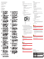
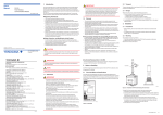
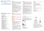
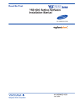
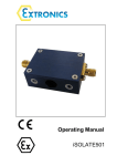
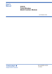
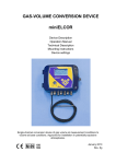
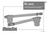
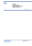
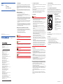
User’s Manual 1. Introduction FN110 Field Wireless Communication Module IM 01W03B01-01EN This manual describes how to use the FN110 Field Wireless Communication Module (hereafter simply referred to as FN110). FN110 enables various sensors with digital communication interface to be operated in field wireless network by converting input/ output of sensor to wireless transmission based on the wireless communication standard ISA100.11a. Your FN110 was precisely calibrated at the factory before shipment. To ensure both safety and efficiency, please read this manual carefully before you operate the FN110. n Regarding This Manual • This manual should be provided to the end user. • The contents of this manual are subject to change without prior notice. • All rights reserved. No part of this manual may be reproduced in any form without Yokogawa’s written permission. • Yokogawa makes no warranty of any kind with regard to this manual, including, but not limited to, implied warranty of merchantability and fitness for a particular purpose. • If any question arises or errors are found, or if any information is missing from this manual, please inform the nearest Yokogawa sales office. • The specifications covered by this manual are limited to those for the standard type under the specified model number break-down and do not cover custom-made instruments. • Please note that changes in the specifications, construction, or component parts of the instrument may not immediately be reflected in this manual at the time of change, provided that postponement of revisions will not cause difficulty to the user from a functional or performance standpoint. n Safety, Protection, and Modification of this Product • In order to protect the operator, product, and system controlled by the product, observe the safety precautions described in this manual. If users handle contrary to these instructions, we cannot guarantee the safety. • Modification of the product is strictly prohibited. • The following safety symbols are used in this manual: 2nd Edition: Dec. 2014 (KP) All Rights Reserved, Copyright © 2014, Yokogawa Electric Corporation WARNING IM 01W03B01-01EN 3rd Edition Indicates a potentially hazardous situation which, if not avoided, could result in death or serious injury. CAUTION Indicates a potentially hazardous situation which, if not avoided, may result in minor or moderate injury or physical damage. It may also be used to alert against unsafe practices. YOKOGAWA ELECTRIC CORPORATION Headquarters 2-9-32, Nakacho, Musashino-shi, Tokyo, 180-8750 JAPAN Phone : 81-422-52-5555 Branch Sales Offices Osaka, Nagoya, Hiroshima, Kurashiki, Fukuoka, Kitakyusyu IMPORTANT Indicates that operating the hardware or software in this manner may damage it or lead to system failure. YOKOGAWA CORPORATION OF AMERICA Head Office 12530 West Airport Blvd, Sugar Land, Texas 77478, USA Phone : 1-281-340-3800 Fax : 1-281-340-3838 Georgia Office 2 Dart Road, Newnan, Georgia 30265, USA Phone : 1-800-888-6400/ 1-770-253-7000 Fax : 1-770-254-0928 NOTE YOKOGAWA AMERICA DO SUL LTDA. Praca Acapulco, 31 - Santo Amaro, Sáo Paulo/SP, BRAZIL, CEP-04675-190 Phone : 55-11-5681-2400 Fax : 55-11-5681-4434 YOKOGAWA EUROPE B. V. Euroweg 2, 3825 HD Amersfoort, THE NETHERLANDS Phone : 31-88-4641000 Fax : 31-88-4641111 YOKOGAWA ELECTRIC CIS LTD. Draws attention to information essential for understanding the operation and features. 1.1 Safe Use of This Product • Users of explosion protected instruments should refer first to “6. Explosion Protected Instrument”. • The use of this instrument is restricted to those who have received appropriate training in the device. • Take care not to create sparks when accessing the instrument or peripheral devices in a hazardous location. • Repair or modification to this instrument by customer will cause malfunction of explosion protect function and hazardous situation. If you need to repair or modification, please contact the nearest Yokogawa office. 1.2 Radio Wave 2. Notes on Handling The FN110 is fully factory-tested before shipment. When the FN110 is delivered, check the appearance for damage. 2.1 Check the Model and Specifications The model name and specifications are written on the nameplate attached to the housing. Verify that the specification indicated in the “Model and Suffix Code” in General Specifications “GS 01W03B01-01EN” is in compliance with the specifications written on the order sheet. Manual number omitting the language code at the end is printed on the nameplate. Check the delivery by reference to the following bundled item list. n Bundled items IMPORTANT • This product is equipped with a wireless module which is designated as a certification of construction type as a wireless facility for 2.4 GHz band low-power data communication system of the Radio Act. Refer to “5.2 Regulatory Compliance Statements” for detail. Due to the designated certification of construction type, users may be subject to legal punishment in case of disassembling or modifying this product. • RF Transmitter power (eirp) The factory default settings of RF transmitter power is 12dBm (current consumption 50mA or less). The maximum settings of RF transmitter power is 14dBm (current consumption 60mA or less). • Microwave ovens and other industrial, scientific and medical equipment, as well as local wireless stations (license required) and specific low-power wireless stations (license not required) for identifying mobile objects used in the production line of a factory, use the same frequency band as this product. Prevent interference with other wireless stations. • Check that local wireless stations and specific low-power wireless stations are not being used in the vicinity before using this product. • If this product causes radio interference in a local wireless station used for identifying mobile objects, change the working frequency or stop the emission of radio waves immediately. For details on how to prevent radio interference, contact our service office. • Although this product has been designed to resist high frequency electrical noise, if a radio transceiver is used near this product or its external wiring, this product may be affected by high frequency noise pickup. To test this, start out from a distance of several meters and slowly approach this product with the transceiver while observing the measurement loop for noise effects. Thereafter use the transceiver outside the range where the noise effects were first observed. F01.ai • Manual (IM 01W03B01-01EN) • Attachment Manual (IM 01W03B0102EN) • Attachment (F9092EY*) • Open Source Software license term (F9092QA) • Protection cap (optional specifications) • EU DECLARATION OF CONFORMITY (F9092QC), if optional specification /KS27 is specified. • The remote antenna cable is not included. *:If you need F9092EY, please purchase F9092EX. F9092EX is a set of F9092EY and an instruction manual. Figure 2.1 Nameplate 2.2 Transport To prevent damage while in transit, leave the FN110 in the original shipping container until it reaches the installation site. 2.3 Storage When storing this product, observe the following precautions. 1. Choose a storage location that satisfies the following requirements. • A location that is not exposed to rain or water. • A location subject to a minimum of vibration or impact. • The temperature and humidity limits refer to “5.1 Specifications”. 2. If at all possible, store the FN110 in factory-shipped condition, that is, in the original shipping container. 1.3 Warranty • The warranty shall cover the period noted on the quotation presented to the purchaser at the time of purchase. Problems occurring during the warranty period shall basically be repaired free of change. • If any problems are experienced with this product, the customer should contact the Yokogawa representative from which this product was purchased or the nearest Yokogawa office. • If a problem arises with this product, please inform us of the nature of the problem and the circumstances under which it developed, including the model specification and serial number. Any diagrams, data and other information you can include in your communication will also be helpful. • The party responsible for the cost of fixing the problem shall be determined by Yokogawa following an investigation conducted by Yokogawa. n The purchaser shall bear the responsibility for repair costs, even during the warranty period, if the malfunction is due to: Grokholskiy per 13 Building 2, 4th Floor 129090, Moscow, RUSSIA Phone : 7-495-737-7868 Fax : 7-495-737-7869 YOKOGAWA CHINA CO., LTD. 3F Tower D Cartelo Crocodile Building, No.568 West Tianshan Road, Shanghai 200335, CHINA Phone : 86-21-62396262 Fax : 86-21-62387866 YOKOGAWA ELECTRIC KOREA CO., LTD. (Yokogawa B/D, Yangpyeong-dong 4-Ga), 21, Seonyu-ro 45-gil, Yeongdeungpo-gu, Seoul, 150-866, KOREA Phone : 82-2-2628-6000 Fax : 82-2-2628-6400 YOKOGAWA ENGINEERING ASIA PTE. LTD. 5 Bedok South Road, Singapore 469270, SINGAPORE Phone : 65-6241-9933 Fax : 65-6241-2606 YOKOGAWA INDIA LTD. Plot No.96, Electronic City Complex, Hosur Road, Bangalore - 560 100, INDIA Phone : 91-80-4158-6000 Fax : 91-80-2852-1442 • Improper and/or inadequate maintenance by the purchaser. • Malfunction or damage due to a failure to handle, use, or store this product in accordance with the design specifications. • Use of this product in question in a location not conforming to the standards specified by Yokogawa, or due to improper maintenance of the installation location. • Failure or damage due to modification or repair by any party except Yokogawa or an approved representative of Yokogawa. • Malfunction or damage from improper relocation of this product in question after delivery. • Reason of force majeure such as fires, earthquakes, storms/floods, thunder/ lightening, or other natural disasters, or disturbances, riots, warfare, or radioactive contamination. YOKOGAWA AUSTRALIA PTY. LTD. Tower A, 112-118 Talavera Road, Macquarie Park NSW 2113, AUSTRALIA Phone : 61-2-8870-1100 Fax : 61-2-8870-1111 YOKOGAWA MIDDLE EAST & AFRICA B.S.C.(C) P.O. Box 10070, Manama, Building 577, Road 2516, Busaiteen 225, Muharraq, Kingdom of BAHRAIN Phone : 973-17358100 Fax : 973-17336100 Apr. '15 Printed in Japan IM 01W03B01-01EN P.1 3.1 Precautions • Before installing, refer to the User’s Manual of the device to be connected to the FN110. • For additional information on the ambient conditions allowed at the installation location, refer to “5.1 Specifications”. 3.2 Mounting The installation procedure is as follows. 1. Check the orientation of the pins, insert FN110 into the connector on the device. 2. Tighten the lock nut to a torque of 1.2 N·m. Removal is the reverse of the above. 2 Lock nut 1 The connector is shipped with a dust cap. Keep the cap attached until the installation to protect the connector. The cap should be stored so that you can use it again when you detach FN110. In an extremely wet condition, use the optional water-proof cap. CAUTION • Before installing, turn off the equipment to be installed. • When installing, secure FN110 by tightening the lock nut. Tightening by screwing the housing instead of the lock nut may cause failure such as cable disconnection. • When using the remote antenna cable, use the dedicated cable provided by Yokogawa as accessories for FN110. • The remote antenna cable and other cables should not be bundled together. • To maintain a good connection between the modules, protect the connector from the corrosive atmosphere by the following treatment. 1. Clean the connection to be protected. 2. Wind the butyl rubber self-bonding tape around the connection. See the manual of the tape about the winding. 3. To protect the butyl rubber self-bonding tape from the environment such as ultraviolet rays and so on, wind vinyl tape (or a vinyl type self-bonding tape) on it. 4. When the tape is necessary, prepare appropriate tape for the installing environment. Do not cover the nameplate by the tapes. 3.3 Installation of an Explosion Protected Instrument Refer to “6. Explosion Protected Instrument”. 4. Operation F02.ai FN110 is used with FN series product (e.g., FN310 Field Wireless Multi-Protocol Module). For the usage of FN110, refer to the User’s Manual of the device to be connected to FN110. Figure 3.1 Installation of FN110 and Sealing of the Connector To install FN110 with remote antenna cable, follow the procedure below. 1. Assemble the mounting bracket and fix it on a 50A (2-inch) pipe. 2. Connect the FN110 and the device the dedicated remote antenna cable. Tighten the connector of the remote antenna cable with a torque of 1.2 N·m. The minimum bend radius should be more than 100mm. 3. Protect the connectors of the FN110 and remote antenna cable as necessary. 4. Fix the remote antenna cable to an appropriate structure to protect the cable from the vibration, wind, and so on. The minimum bending radius for fixing in the state maintained for a long period should be more than 100 mm. 5. Fix the FN110 to the mounting bracket. Bracket 2-inch pipe fastening nut Spring washer FN110 holder bolt U-bolt nut FN110 FN110 mounting bracket U-bolt 2-inch pipe mounting bracket Bracket fastening bolt Remote antenna cable FN110 holder F03.ai Figure 3.2 Vertical Pipe Mounting of FN110 FN110 holder bolt FN110 FN110 mounting bracket FN110 holder Remote antenna cable Bracket fastening bolt U-bolt nut Spring washer Bracket fastening nut U-bolt 2-inch pipe mounting bracket 5. General Specifications Please refer to GS 01W03B01-01EN for the latest information. 5.1 Specifications Communication Protocol: ISA100.11a (IEEE802.15.4) Data Rate: 250 kbps Frequency: 2400 - 2483.5 MHz license free ISM band Radio Security: AES 128 bit RF Transmitter Power: 12 dBm (eirp) Antenna: 2 dBi (Omni directional) Power Supply Voltage: 2.9 - 4.8 V Consumption Current: Max. 60 mA Update Period: 1 to 3600 s* * Depends on module to connect this product. Refer to the General Specifications of the products that are connected to this product. Digital Communication for FN series: Communication Mode: Half-duplex communication (RS485 compliant) Communication Speed: 9600 bps Communication Distance: Max 20 m (dedicated cable) Diagnostic Functions: Power failures, wired communication failures, firmware internal errors, memory errors, abnormal temperature Software Download Function: Software download function enables you to update wireless field device software via ISA100 Wireless communication. Ambient Temperature Limits: Operating: -40 to 85°C (altitude: up to 3000 m) Storage: -40 to 85°C Ambient Humidity Limits: Operating: 0 to 100% RH (non-condensation) Storage: 0 to 100% RH (non-condensation) Ambient Temperature Gradient: Operating: ±10°C/h or less Storage: ±20°C/h or less Vibration Resistance: 0.21 mm P-P (10 - 60 Hz), 3 G (60 - 2 kHz) Shock Resistance: 50 G 11 ms Grounding: Ground through the mating of the metal shell. Please ensure that the ground terminal is connected to an appropriate ground. Weight: 100 g 5.2 Regulatory Compliance Statements This product satisfies the following standards. * Please confirm that an installation region fulfills an applicable standard. If additional regulatory information and approvals are required, contact a Yokogawa representative. Telecommunication Compliance: MIC Identification (Japan) Applied to a wireless module that incorporates. Construction Design Attestation Number: 006-000202 FCC Approval (United States) (Part 15B, 15C) This device complies with part 15 of the FCC Rules. Operation in subject to following two conditions: (1) This device may not cause harmful interface, and (2) this device must accept any interference received, including interference that may cause undesired operation. FCC WARNING: Changes or modifications not expressly approved by the party responsible for compliance could void the user’s authority to operate the equipment. NOTE This equipment has been tested and found to comply with the limits for a Class A digital device, pursuant to part 15 of the FCC Rules. These limits are designed to provide reasonable protection against harmful interference when the equipment is operated in a commercial environment. This equipment generates, uses, and can radiate radio frequency energy and, if not installed and used in accordance with the instruction manual, may cause harmful interference to radio communications. Operation of this equipment in a residential area is likely to cause harmful interference in which case the user will be required to correct the interference at his own expense. Co-located: This transmitter must not be co-located or operated in conjunction with any other antenna or transmitter. RF Exposure Compliance: This equipment complies with FCC radiation exposure limits set forth for an uncontrolled environment and meets the FCC radio frequency (RF) Exposure Guidelines. This equipment should be installed and operated keeping the radiator at least 20 cm or more away from person’s body. IC Approval (Canada) (RSS-Gen) This device complies with Industry Canada license-exempt RSS standard(s). Operation is subject to the following two conditions: (1) this device may not cause interference, and (2) this device must accept any interference, including interference that may cause undesired operation of the device. French: Le présent appareil est conforme aux CNR d'Industrie Canada applicables aux appareils radio exempts de licence. L'exploitation est autorisée aux deux conditions suivantes: (1) l'appareil ne doit pas produire de brouillage, et (2) l'utilisateur de l'appareil doit accepter tout brouillage radioélectrique subi, même si le brouillage est susceptible d'en compromettre le fonctionnement. (RSS-102) This equipment complies with IC radiation exposure limits set forth for an uncontrolled environment and meets RSS-102 of the IC radio frequency (RF) Exposure rules. This equipment should be installed and operated keeping the radiator at least 20 cm or more away from person’s body (excluding extremities: hands, wrists, feet and ankles). French: Cet équipement est conforme aux limites d’exposition aux rayonnements énoncées pour un environnement non contrôlé et respecte les règles d’exposition aux fréquences radioélectriques (RF) CNR-102 de l’IC. Cet équipement doit être installé et utilisé en gardant une distance de 20 cm ou plus entre le dispositif rayonnant et le corps (à l’exception des extrémités : mains, poignets, pieds et chevilles). R&TTE Directive (EU Countries) We, Yokogawa Electric Corporation hereby declare that this equipment, model FN110 is in compliance with the essential requirements and other relevant provisions of Directive 1999/5/EC. The EU declaration of conformity for R&TTE for this product can be found at http://www.yokogawa.com/fld/ The Authorized Representative for this product in the EEA is: Yokogawa Europe B.V. Euroweg 2, 3825 HD Amersfoort, THE NETHERLANDS. CE Conformity: Radio Spectrum: EN 300 328 EMC: EN 301 489-1, EN301 489-17, EN61326-1 Class A Table 2 (For use in industrial locations), EN55011 Class A CAUTION This instrument is a Class A product, and it is designed for use in the industrial environment. Please use this instrument in the industrial environment only. Safety: EN61010-1 (Indoor/Outdoor use), EN62479 (1) Pollution Degree 2 “Pollution degree” describes the degree to which a solid, liquid, or gas which deteriorates dielectric strength or surface resistivity is adhering. “2” applies to normal indoor atmosphere. Normally, only non-conductive pollution occurs. Occasionally, however, temporary conductivity caused by condensation must be expected. (2) Installation Category I “Overvoltage category (Installation category)” describes a number which defines a transient overvoltage condition. It implies the regulation for impulse with stand voltage. “I” applies to electrical equipment which is supplied from the circuit when appropriate transient overvoltage control means (interfaces) are provided. Degrees of Protection: IP66 IP66 rating applies when the connector is properly tightened. Explosion Protected Types: TIIS, ATEX, IECEx Approvals FM (United States or Canada) Approvals under pending 5.3 Model and Suffix Codes Refer to the General Specification “GS 01W03B01-01EN”. 5.4 External Dimensions and Pin Assignment Unit: mm (approx. inch) Pin 90 (3.54) IMPORTANT 14 (0.56) 3. Installation F05.ai 2-inch pipe F04.ai Figure 3.3 Horizontal Pipe Mounting of FN110 Figure 3.4 Sealing of the Remote Antenna Cable Ø23 (0.91) Signal 1 Not Connected 2 Signal Ground 3 Power Supply 4 Transmit/Receive Data positive 5 Transmit/Receive Data negative 21 (0.83) 123 45 Ø2 3 (0 .9 1) F06.ai Plug type of FN110: JR13WPI-5P (connector mating with type of JR13WRI-5S or JR13WJI-5S) IM 01W03B01-01EN P.2 6. Explosion Protected Instrument 6.3.2. Installation (1) Technical Data Caution for ATEX Intrinsically safe type. This chapter includes a control drawing of IIE023-A71. Note 1.Model FN110 Field Wireless Communication Module with optional code /KS27 for potentially explosive atmospheres: • No.: Presafe 15ATEX6309X • Applicable Standard: EN 60079-0:2012/A11:2013, EN 60079-11:2012, EN60529:1991/A2:2013 • Type of Protection and Marking code: Ex ia IIC T4 Ga • Group: II • Category: 1G • Ambient Temperature: -40°C to 70°C • Enclosure: IP66 Note 2. Electrical Parameters Ui: 5.88 V, Ii: 0.62 A, Pi: 0.92W, Ci: 5.8μF, Li: 7uH Note 3. Installation • Installation should be in accordance with local installation requirements. (Refer to “Figure 6.3.1 Control Drawing for ATEX Certification” • Control Drawing (ATEX) 6.1. FM Approval (United States) Approval under pending. 6.2. FM Approval (Canada) Approval under pending. 6.3. ATEX Certification 6.3.1. ATEX Documentation This is only applicable to the countries in European Union. GB DK SK CZ Hazardous Area LT E LV FN110 Field Wireless Communication Module Ui: 5.88 V Ii: 0.62 A Pi: 0.92 W Ci: 5.8 µF Li: 7 µH … I NC 1 GND 2 Vcc 3 DATA_P 4 DATA_N 5 Hazardous Area or Non-Hazardous Area IS Apparatus or Associated Apparatus (4) Nameplate Please refer to “Figure 2.1 Nameplate” for ATEX Certification. MODEL: Specified model code. SUFFIX: Specified suffix code. STYLE: Style code. SUPPLY: Supply voltage. OUTPUT: Output signal. CAL RNG: Calibration range. No.: Serial number. TOKYO 180-8750 JAPAN: The manufacturer name and the address*1. *1: “180-8750” is a zip code which represents the address: 2-9-32 Nakacho, Musashino-shi, Tokyo, Japan. 6.4. IECEx Certification Caution for IECEx Intrinsically safe type. This chapter includes a control drawing of IIE023-A71. Note 1.Model FN110 Field Wireless Communication Module with optional code /SS27 for potentially explosive atmospheres. • No.: IECEx PRE 15.0015X • Applicable Standard: IEC 60079-0:2011, IEC 60079-11:2011, IEC 60529:2013 • Type of Protection and Marking code: Ex ia IIC T4 Ga • Ambient Temperature: -40°C to 70°C • Enclosure: IP66 Note 2. Output Parameters Ui: 5.88 V, Ii: 0.62 A, Pi: 0.92W, Ci: 5.8μF, Li: 7uH Note 3. Installation • Installation should be in accordance with local installation requirements. Refer to “Figure 6.3.1 Control Drawing for ATEX Certification” and Note 4 of “6.3.2 Installation”. Note 4. Maintenance and Repair F08.ai Figure 6.3.1 Control Drawing, IIE023-A71 for ATEX Certification NL Note 4.FN110 Field Wireless Module is connected to IS Apparatus (or Associated Apparatus), or it is directly connected to IS Apparatus (or Associated Apparatus). The equipment satisfies the requirements for IP66 only when it is connected to a connector JR13WRI-5S or JR13WJI-5S (Hirose Electric). Appropriate type of socket must be used in accordance with the instruction manual. Note 5. Special conditions for Safe Use • Precautions shall be taken to minimize the risk from electrostatic discharge of nonmetallic parts. • When Field Wireless Communication Module is used in a potentially explosive atmosphere requiring equipment category 1 G, it must be installed such that, even in the event of rare incidents, ignition sources due to impact and/or friction sparks are excluded. EST PL SF WARNING SLO P Potential electrostatic charging hazard - Electrostatic charge may cause an explosion hazard. Avoid any actions that cause the generation of electrostatic charge, such as rubbing with a dry cloth on the product. H WARNING The instrument modification or parts replacement by other than an authorized Representative of Yokogawa Electric Corporation is prohibited and will void IECEx Intrinsically safe Certification. Note 5. Special conditions for Safe Use Precautions shall be taken to minimize the risk from electrostatic discharge of nonmetallic parts. When Field Wireless Communication Module is used in a potentially explosive atmosphere requiring EPL Ga, it must be installed such that, even in the event of rare incidents, ignition sources due to impact and/or friction sparks are excluded. WARNING Potential electrostatic charging hazard - Electrostatic charge may cause an explosion hazard. Avoid any actions that cause the generation of electrostatic charge, such as rubbing with a dry cloth on the product. (2) Operation F WARNING BG Take care not to generate mechanical sparking when access to the instrument and peripheral devices in a hazardous location. D (3) Maintenance and repair RO S WARNING The instrument modification or parts replacement by other than an authorized Representative of Yokogawa Electric Corporation is prohibited and will void the certification. M GR F07.ai Revision Record Title: FN110 Field Wireless Communication Module Manual No.: IM 01W03B01-01EN Edition Date Page 1st July 2014 — New Publication. Revised item 2nd Dec. 2014 1 2 2.1Add Bundled items 5.2Add CSA Safety Requirements Modify Explosion-Proot Types 3rd Dec, 2015 — Add ATEX and IECEx Certification. IM 01W03B01-01EN P.3