1
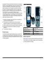
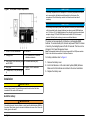
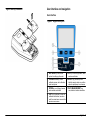
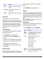
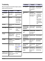
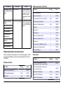
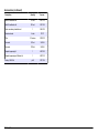
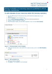
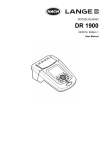
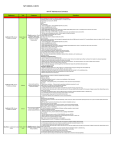
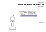
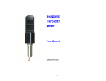
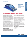
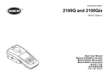
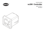
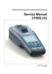
DOC022.53.80041
2100Q and 2100Qis
01/2010, Edition 1
User Manual
For Sales & Service Contact
2650 E. 40th Ave. • Denver, CO 80205
Phone 303-320-4764 • Fax 303-322-7242
1-800-833-7958
www.geotechenv.com
Table of Contents
Specifications .................................................................................................................................................................................3
General Information ....................................................................................................................................................................3
Safety information .............................................................................................................................................................................4
Use of hazard information .................................................................................................................................................................4
Precautionary labels ..........................................................................................................................................................................4
Certification .......................................................................................................................................................................................4
Product overview ...............................................................................................................................................................................5
Product components .........................................................................................................................................................................5
Installation ........................................................................................................................................................................................6
Install the battery ...............................................................................................................................................................................6
User interface and navigation ..............................................................................................................................................7
User interface ....................................................................................................................................................................................7
Display description ............................................................................................................................................................................8
Navigation .........................................................................................................................................................................................8
Start-up ...............................................................................................................................................................................................8
Turn the meter on and off ..................................................................................................................................................................8
Change the language .......................................................................................................................................................................8
Change the date and time ................................................................................................................................................................9
Standard operations ...................................................................................................................................................................9
Use a sample ID ................................................................................................................................................................................9
Use an operator ID ............................................................................................................................................................................9
Calibrate the turbidimeter with StablCal® Standards ........................................................................................................................9
Turbidity measurement ....................................................................................................................................................................10
Measurement notes .................................................................................................................................................................10
Turbidity measurement procedure ...........................................................................................................................................11
Data management ......................................................................................................................................................................11
About stored data ............................................................................................................................................................................11
View data log ...................................................................................................................................................................................11
Delete data log ................................................................................................................................................................................12
1
Table of Contents
Send stored data .............................................................................................................................................................................12
Advanced operations ...............................................................................................................................................................12
Display contrast ...............................................................................................................................................................................12
Power management ........................................................................................................................................................................12
Set the sound options ......................................................................................................................................................................12
Security options ...............................................................................................................................................................................13
Turn security options on ...........................................................................................................................................................13
View meter information ....................................................................................................................................................................13
Calibration .......................................................................................................................................................................................13
Calibration options ...................................................................................................................................................................13
Calibration standard overview ..................................................................................................................................................14
StablCal® RapidCal™ calibration .............................................................................................................................................15
Verification options ...................................................................................................................................................................16
Calibration verification (Verify Cal) ...........................................................................................................................................16
Reading modes ...............................................................................................................................................................................16
Apply silicone oil to a sample cell ....................................................................................................................................................17
Indexing a single cell .......................................................................................................................................................................17
Maintenance ..................................................................................................................................................................................19
Clean the meter ...............................................................................................................................................................................19
Store the sample cells .....................................................................................................................................................................19
Replace the battery .........................................................................................................................................................................19
Replace the lamp ............................................................................................................................................................................19
Troubleshooting ..........................................................................................................................................................................22
Replacement parts and accessories ..............................................................................................................................23
Replacement parts .........................................................................................................................................................................23
Accessories ....................................................................................................................................................................................23
Index ...................................................................................................................................................................................................25
2
Specifications
Specifications are subject to change without notice.
Specification
Details
Measurement
method
Ratio turbidimetric determination using a primary
nephelometric light scatter signal (90°) to the transmitted light
scatter signal.
Regulatory
Details
Power
requirement
AC 100–240 V , 50/60 Hz (with power or USB/power module)
2100Q: Tungsten filament lamp
2100Qis: Light-emitting diode (LED) at 860 nm
Range
0–1000 NTU (FNU)
Accuracy
±2% of reading plus stray light from 0–1000 NTU (FNU)
4 AA alkaline batteries
Rechargeable NiMH (for use with USB/power module)
Operating
conditions
Temperature: 0 to 50 °C (32 to 122 °F)
Storage
conditions
–40 to 60 °C (–40 to 140 °F), instrument only
Interface
Optional USB
Sample required
15 mL (0.5 oz.)
Sample cells
Round cells 60 x 25 mm (2.36 x 1 in.) borosilicate glass with
screw caps
2100Q: Meets EPA Method 180.1
2100Qis: Meets ISO 7027
Lamp source
Specification
Relative Humidity: 0–90% at 30 °C, 0–80% at 40 °C, 0–70%
at 50 °C, noncondensing
Repeatability
±1% of reading or 0.01 NTU (FNU), whichever is greater
Dimensions
22.9 x 10.7 x 7.7 cm (9.0 x 4.2 x 3.0 in.)
Resolution
0.01 NTU on lowest range
Weight
530 g (1.17 lb) without batteries
Stray light
≤ 0.02 NTU (FNU)
Signal averaging
Selectable on or off
Detector
Silicon Photodiode
Reading modes
Normal (Push to Read), Signal Averaging or Rapidly Settling
Turbidity™
Calibration
options
Single step RapidCal™ for Low-Level Regulatory Reporting
from 0–40 NTU (FNU)
Full range calibration from 0–1000 NTU (FNU)
Calibration to degrees of turbidity
Calibration logger
Records the last 25 successful calibrations
Verification logger
Logs the last 250 successful verifications
Data logger
500 records
620 g (1.37 lb) with four AA alkaline batteries
Meter enclosure
rating
IP67 (closed lid, battery and module compartment excluded)
Protection class
Power supply: Class II
Certification
CE certified
Warranty
1 year (EU: 2 years)
General Information
In no event will the manufacturer be liable for direct, indirect, special,
incidental or consequential damages resulting from any defect or omission
in this manual. The manufacturer reserves the right to make changes in
this manual and the products it describes at any time, without notice or
obligation. Revised editions are found on the manufacturer’s website.
English 3
Safety information
Please read this entire manual before unpacking, setting up or operating
this equipment. Pay attention to all danger and caution statements. Failure
to do so could result in serious injury to the operator or damage to the
equipment.
Make sure that the protection provided by this equipment is not impaired,
do not use or install this equipment in any manner other than that specified
in this manual.
Use of hazard information
DANGER
Indicates a potentially or imminently hazardous situation which, if not avoided, will
result in death or serious injury.
WARNING
Indicates a potentially or imminently hazardous situation which, if not avoided,
could result in death or serious injury.
CAUTION
Indicates a potentially hazardous situation that may result in minor or moderate
injury.
NOTICE
Indicates a situation which, if not avoided, may cause damage to the instrument.
Information that requires special emphasis.
Precautionary labels
Read all labels and tags attached to the instrument. Personal injury or
damage to the instrument could occur if not observed. A symbol, if noted
on the instrument, will be included with a danger or caution statement in
the manual.
This symbol, if noted on the instrument, references the instruction
manual for operation and/or safety information.
This symbol, when noted on a product enclosure or barrier, indicates
that a risk of electrical shock and/or electrocution exists.
Electrical equipment marked with this symbol may not be disposed
of in European public disposal systems after 12 August of 2005. In
conformity with European local and national regulations (EU
Directive 2002/98/EC), European electrical equipment users must
now return old or end-of-life equipment to the Producer for disposal
at no charge to the user.
Note: For return for recycling, please contact the equipment producer or supplier
for instructions on how to return end-of-life equipment, producer-supplied
electrical accessories, and all auxillary items for proper disposal.
Certification
Canadian Radio Interference-Causing Equipment Regulation,
IECS-003, Class A:
Supporting test records reside with the manufacturer.
This Class A digital apparatus meets all requirements of the Canadian
Interference-Causing Equipment Regulations.
Cet appareil numèrique de la classe A respecte toutes les exigences du
Rëglement sur le matériel brouilleur du Canada.
FCC Part 15, Class "A" Limits
Supporting test records reside with the manufacturer. The device complies
with Part 15 of the FCC Rules. Operation is subject to the following
conditions:
1. The equipment may not cause harmful interference.
2. The equipment must accept any interference received, including
interference that may cause undesired operation.
Changes or modifications to this equipment not expressly approved by the
party responsible for compliance could void the user's authority to operate
4 English
the equipment. This equipment has been tested and found to comply with
the limits for a Class A digital device, pursuant to Part 15 of the FCC rules.
These limits are designed to provide reasonable protection against
harmful interference when the equipment is operated in a commercial
environment. This equipment generates, uses and can radiate radio
frequency energy and, if not installed and used in accordance with the
instruction manual, may cause harmful interference to radio
communications. Operation of this equipment in a residential area is likely
to cause harmful interference, in which case the user will be required to
correct the interference at their expense. The following techniques can be
used to reduce interference problems:
1. Disconnect the equipment from its power source to verify that it is or
is not the source of the interference.
2. If the equipment is connected to the same outlet as the device
experiencing interference, connect the equipment to a different outlet.
3. Move the equipment away from the device receiving the interference.
4. Reposition the receiving antenna for the device receiving the
interference.
5. Try combinations of the above.
Product overview
The 2100Q and 2100Qis portable turbidimeters measure turbidity from 0
to 1000 NTU (FNU). Primarily for field use, the portable meter operates on
four AA batteries. Data can be stored and transferred to a printer, computer
or USB storage device.
Figure 1 Product overview
1 Power on or off
5 Alignment arrow
2 Backlight keys (+ and -)
6 Module
3 Sample cell holder with lid
7 Lamp compartment
4 Attachment for lanyard
8 Battery compartment
Product components
Refer to Figure 2 to make sure that all components have been received.
If any of these items are missing or damaged, contact the manufacturer
or a sales representative immediately.
English 5
Figure 2 2100Q and 2100Qis components
NOTICE
The battery compartment is not waterproof. If the battery compartment becomes
wet, remove and dry the batteries and thoroughly dry the interior of the
compartment. Check the battery contacts for corrosion and clean them if
necessary.
NOTICE
When using nickel metal hydride (NiMH) batteries, the battery icon will not indicate
a full charge after freshly charged batteries have been inserted (NiMH batteries
are 1.2 V versus 1.5 V for alkaline batteries). Even though the icon does not indicate
complete charge, 2300 mAH NiMH batteries will achieve 90% of instrument
operation lifetime (before recharge) versus new alkaline batteries.
The meter can be powered with AA alkaline or rechargeable NiMH
batteries. To conserve battery life, the meter will power off after 10 minutes
of inactivity, the backlight powers off after 30 seconds. This time can be
changed in the Power Management menu.
1 2100Q or 2100Qis turbidimeter
6 Silicone oil
2 Carrying case
7 20, 100 and 800 NTU StablCal
calibration standards
3 User manual, Quick reference guide
and CD-ROM
8 AA alkaline batteries (pk/4)
4 Oiling cloth
9 StablCal 10 NTU verification
standard
5 1" sample cell (10 mL) with cap (pk/
6)
Installation
CAUTION
Personal injury hazard. Only qualified personnel should conduct the tasks
described in this section of the manual.
Install the battery
WARNING
Potential fire hazard. Use only alkaline or nickel metal hydride batteries (NiMH) in
the meter. Other battery types or incorrect installation can cause a fire. Never mix
battery types in the meter.
6 English
Note: Rechargeable batteries will only be recharged with the USB/power module.
Refer to the module documentation for further information.
For battery installation refer to Figure 3.
1. Remove the battery cover.
2. Install 4 AA alkaline or 4 AA nickel metal hydride (NiMH) batteries.
Make sure that the batteries are installed in the correct orientation.
3. Replace the battery cover.
Figure 3 Battery installation
User interface and navigation
User interface
Figure 4 Keypad description
1 SETTINGS key: select menu
options for setting up the meter
5 UP key: scroll through menus, enter
numbers and letters
2 CALIBRATION key: shows
calibration screen, start calibration,
select cal options
6 RIGHT key (contextual): read
turbidity sample, selects or confirms
options, opens/jumps to sub-menus
3 DOWN key: scroll through menus,
enter numbers and letters
7 DATA MANAGEMENT key:
view, delete or transfer stored data
4 LEFT key (contextual): access for
calibration verification, cancels or
exits the current menu screen to the
previous menu screen
English 7
Display description
Navigation
The measurement screen shows the turbidity, unit, calibration status, date
and time, operator ID (if setup) and sample ID (if setup). Refer to
Figure 5.
The meter contains a Settings menu, Reading Options menu, Calibration
Options menu and Calibration Verification Options menu to change
various options. Use the UP and DOWN keys to highlight different options.
Push the RIGHT key to select an option. There are two ways to change
options:
Figure 5 Single screen display
1. Select an option from a list: Use the UP and DOWN keys to select an
option. If check boxes are shown, more than one option can be
selected. Push the LEFT key under Select.
Note: To deselect check boxes, push the LEFT key under Deselect.
2. Enter an option value using the arrow keys:
Push the UP and DOWN keys to enter or change a value.
3. Push the RIGHT key to advance to the next space.
4. Push the RIGHT key under OK to accept the value.
Start-up
Turn the meter on and off
1 Operator identification
9 NTU (Nephelometric Turbidity Unit)
or FNU (Formazin Turbidity Unit)
Push the ON/OFF key to turn on or turn off the meter. If the meter does
not turn on, make sure that the batteries, or the module, are properly
installed or that the AC power supply is properly connected to an electrical
outlet.
2 Sample identification
10 Reading mode: Rapidly Settling
Turbidity (Target icon)
Note: The Auto-Shutoff option can also be used to turn off the meter. Refer to Power
management on page 12.
3 Stability or display lock indicator
11 Reading mode: Signal Average (Xbar icon)
Change the language
4 Calibration status indicator
(Calibration OK=pass)
12 Time
There are three options to set the language:
5 Calibration status indicator
(Calibration ?=fail)
13 Date
6 Parameter title
14 Read (contextual: OK, Select)
7 AC power icon
15 Options (contextual)
• The display language is selected when the meter is powered on for the
first time.
• The display language is selected when the power key is pushed and
held.
• The language can be changed from the Settings menu.
8 Battery icon
16 Verification calibration
8 English
1. Select a language from the list. Confirm with OK.
2. Push Done when the update is complete.
Option
Description
Current ID
Select an ID from a list. The current ID will be
associated with sample data until a different ID is
selected.
Create a New
Sample ID
Enter a name for a new sample ID.
Delete Sample ID
Delete an existing sample ID.
Change the date and time
The date and time can be changed from the Date & Time menu.
1. Push the SETTINGS key and select Date & Time.
2. Update the time and date information:
Option
Description
Use an operator ID
Format
Select one of the formats for the date and time:
The operator ID tag associates readings with an individual operator. All
stored data will include this ID.
yyyy-mm-dd 24h
yyyy-mm-dd 12h
dd-mm-yyyy 24h
dd-mm-yyyy 12h
1. Select Operator ID in the Settings menu.
2. Select, create or delete an operator ID:
mm/dd/yyyy 24h
Option
Description
mm/dd/yyyy 12h
Current ID
Select an ID from a list. The current ID will be
associated with sample data until a different ID is
selected.
Create a New
Operator ID
Enter a name for a new operator ID (maximum 10
names can be entered).
Delete Operator ID
Delete an existing operator ID.
Date
Enter the current date
Time
Enter the current time
The current date and time will be shown on the display.
After the date and time setup, the meter is ready to take a reading.
Standard operations
Use a sample ID
Calibrate the turbidimeter with StablCal® Standards
Note: For best accuracy use the same sample cell or four matched sample cells for
all readings during calibration. Insert the sample cell in the instrument cell
compartment so the diamond or orientation mark aligns with the raised orientation
mark in front of the cell compartment.
The sample ID tag is used to associate readings with a particular sample
location. If assigned, stored data will include this ID.
1. Select Sample ID in the Settings menu.
2. Select, create or delete a sample ID:
English 9
Turbidity measurement
WARNING
Potential explosion and fire hazard. This turbidimeter is designed for water based
samples. Do not measure solvent or combustible based samples.
1. Push the
CALIBRATION key to
enter the Calibration
mode. Follow the
instructions on the
display.
Note: Gently invert each
standard before
inserting the standard.
2. Insert the 20 NTU
StablCal Standard and
close the lid.
Note: The standard to
be inserted is bordered.
3. Push Read. The
display shows
Stabilizing and then
shows the result.
Readings can be taken with the Normal reading mode, Signal Average
mode or in the Rapidly Settling Turbidity mode. Refer to Reading modes
on page 16 for more information. For accurate turbidity readings use
clean sample cells and remove air bubbles (degassing).
Measurement notes
Proper measurement techniques are important in minimizing the effects
of instrument variation, stray light and air bubbles. Use the following
measurement notes for proper measurements.
Instrument
• Make sure that the meter is placed on a level, stationary surface during
the measurement.
Note: Do not hold the meter in the hand during measurement.
• Always close the sample compartment lid during measurement,
calibration and storage.
• Remove sample cell and batteries from the instrument if the instrument
is stored for an extended time period (more than a month).
• Keep the sample compartment lid closed to prevent the entry of dust
and dirt.
4. Repeat Step 2 and 3
with the 100 NTU and
800 NTU StablCal
Standard.
Note: Push Done to
complete a 2 point
calibration.
5. Push Done to review
the calibration details.
6. Push Store to save
the results.
After a calibration is
complete, the meter
automatically goes into
the Verify Cal mode.
Refer to Calibration
verification (Verify Cal)
on page 16.
Sample cells
• Always cap the sample cell to prevent spillage of the sample into the
instrument.
• Always use clean sample cells in good condition. Dirty, scratched or
damaged cells can cause inaccurate readings.
• Make sure that cold samples do not “fog” the sample cell.
• Store sample cells filled with distilled or deionized water and cap tightly.
Measurement
10 English
• Measure samples immediately to prevent temperature changes and
settling. Before a measurement is taken, always make sure that the
sample is homogeneous throughout.
• Avoid sample dilution when possible.
• Avoid operation in direct sunlight.
Turbidity measurement procedure
Note: Before a measurement is taken, always make sure that the sample is
homogeneous throughout.
4. Push the Power key
to turn the meter on.
Place the instrument on
a flat, sturdy surface.
Note: Do not hold the
instrument while making
measurements.
1. Collect a
representative sample
in a clean container. Fill
a sample cell to the line
(about 15 mL). Take
care to handle the
sample cell by the top.
Cap the cell.
2. Wipe the cell with a
soft, lint-free cloth to
remove water spots and
fingerprints.
3. Apply a thin film of
silicone oil. Wipe with a
soft cloth to obtain an
even film over the entire
surface (Apply silicone
oil to a sample cell
on page 17).
5. Gently invert and then
insert the sample cell in
the instrument cell
compartment so the
diamond or orientation
mark aligns with the
raised orientation mark
in front of the cell
compartment. Close the
lid.
6. Push Read. The
display shows
Stabilizing then the
turbidity in NTU (FNU).
The result is shown and
stored automatically
(Refer to Data
management
on page 11)
Data management
About stored data
The following types of data are stored in the data log:
• Reading Log: stores automatically each time a sample reading is taken
(500 records).
• Calibration Log: stores only when Store is selected at the end of a
calibration (25 records).
• Verify Cal Log: stores only after Done is selected at the end of a
verification calibration (250 records).
When the data log becomes full, the oldest data point is deleted when more
data is added to the log.
View data log
The data log contains Reading Log, Calibration Log and Verify Cal log. All
logs can be sorted by date.
English 11
1. Push the DATA MANAGEMENT key.
2. Select View Data Log to view the stored data.
3. Push Select to view additional information.
Option
Description
Reading Log
Reading Log—shows the date, time and reading mode and
associated calibration data.
Calibration Log
Calibration Log—shows the date and time of calibration
data and additional information about the calibration.
Verify Cal Log
Verify Cal Log—shows the calibration verification date and
time and additional information about the verification.
All Logs by Date The most recent data and additional information is shown.
The icons show whether the data is from a reading,
calibration or calibration verification and identifies the
reading mode, if applicable.
Advanced operations
Display contrast
1. Push the SETTINGS key and select Display Contrast.
2. Use the UP and DOWN key to adjust the contrast of the display and
push OK.
Power management
Use power management to change the backlight option and the battery
saving auto-shutoff option.
Note: Power management is not active when the meter is connected to AC power.
1. Push the SETTINGS key and select Power Management.
2. Select which display option to change.
Delete data log
Option
Description
There are two possibilities to delete stored readings in the Data
Management menu:
Backlight
The display is illuminated. To maximize battery life, select a
time period after which the backlight will automatically power off
if no key is pushed: 10 s, 20 s, 30 s,1 min, 2 min, 5 min
Note: The Backlight keys (Figure 1 on page 5) will turn the
backlight on and off.
AutoShutoff
To maximize battery life, set a time period after which the meter
will automatically power off if no key is pushed: 1 min, 2 min, 5
min, 10 min, 30 min, 1 h
1. Push the DATA MANAGEMENT key and select Delete Data Log.
Option
Description
Delete Last Reading Only the last reading stored can be deleted until a new
reading is taken and stored.
Delete All Logs
The entire Reading Log can be deleted at once.
Set the sound options
Send stored data
The meter can make an audible sound when a key is pushed, when a
reading is complete or when the calibration reminder is due.
Data can be stored and transferred to a printer, computer or USB storage
device. The data will be formatted as an XML file. Install the USB/power
module to the meter and to AC power. Refer to the module documentation
for more information.
1. Push SETTINGS and select Sounds.
2. Select which events will produce an audible sound. Multiple items can
be selected.
12 English
Option
Description
Key Press
The meter will make an audible sound whenever a key
is pushed.
Reading complete The meter will make an audible sound whenever a
reading is completed.
Reminders
The meter will make an audible sound when a calibration
is due.
Security options
The Security Options menu is used to protect the meter setup.
The Setup Date and Time, Delete Data Log, Restoring Factory Defaults
and Restore Factory Cal screens are not accessible without a password.
Store the password in a safe and accessible place. If the specified
password is forgotten and Security Options is turned on, the operator is
locked out of the restricted menus. Contact technical support if the
password is lost.
Turn security options on
The security options and the set password options are used together to
prevent access to restricted menus.
1. Push the SETTINGS key and select Security Options.
2. Select Edit Password and use the UP and DOWN keys to set a
password.
3. Select Security On to enable the password setting. The requirement
for the password entry is controlled by setting Security Options on or
off.
Operator and Sample IDs. 10 Operator IDs and 100 Sample IDs are
available.
1. Push the SETTINGS key and select Meter Information.
Calibration
The portable turbidimeter is calibrated with Formazin Primary Standards
at the factory. The meter should be calibrated upon receipt for best results.
The manufacturer recommends calibration with a primary standard such
as StablCal® Stabilized Standards or with formazin standards every three
months.
Note: Set Cal Reminder Repeat in the Calibration Options menu for periodical
calibration. Verify the calibration once a week.
Calibration options
The calibration options contain Calibration History, Calibration Curves, Cal
Reminder Repeat and Restore Factory Calibration.
1. Push the CALIBRATION key and then the UPand DOWN key.
Option
Description
Calibration
History
The calibration history shows a list of the times when the
meter was calibrated. Select a date and time to view a
summary of the calibration data.
Cal.Curve
Select one of the calibration curves for calibration:
StablCal® RapidCal™ (0–40 NTU)
StablCal® (0–1000 NTU)
Formazin RapidCal™ (0–40 NTU)
Formazin (0–1000 NTU)
Note: Set the Security to Off to disable the password setting.
Degrees (0–100 mg/L)
4. Push the ON/OFF key to turn off and on the meter to activate the
password settings.
View meter information
The instrument information menu shows specific information such as the
meter name, model number, software version, serial number and available
SDVB (0–1000 NTU)
Custom (0–1000 NTU)
Cal Reminder
Repeat
The meter will make an audible sound when calibration is
due. Select one of the following options for time interval and
push OK: Off, 1 d, 7 d, 30 d, 60 d, 90 d
English 13
Option
Description
Restore
Factory
Calibration
All user calibrations will be deleted. The original factory
calibration is restored.
Calibration standard overview
Refer to Table 1 for the calibration standard overview.
Table 1 Calibration overview
Type of calibration
StablCal®
RapidCal™
Required standards
(0–
–
20 NTU –
–
StablCal® (0–1000 NTU)
–
20 NTU 100 NTU 800 NTU
Formazin RapidCal™ (0–
40 NTU)
Typically deionized
or distilled water1
20 NTU –
Formazin (0–1000 NTU)
Typically deionized
or distilled water1
20 NTU 100 NTU 800 NTU
Degrees (0–100 mg/L)
Typically deionized
or distilled water1
20 NTU 100 NTU –
SDVB (0–1000 NTU)
Typically deionized
or distilled water1
20 NTU 100 NTU 800 NTU
Custom (0–1000 NTU)
Typically deionized
or distilled water1
Select values
40 NTU)
1
–
The water must have a turbidity <0.5 NTU to prepare the calibration standards.
14 English
StablCal® RapidCal™ calibration
1. Push the
CALIBRATION key to
enter the Calibration
mode. Follow the
instructions on the
display.
Note: Gently invert each
standard before
inserting the standard.
2. Push the UP and
DOWN key to access
Cal Options and then
select Cal.Curve.
3. Select StablCal®
RapidCal™ from the list
and push OK.
4. Insert the 20 NTU
StablCal Standard and
close the lid.
Note: The standard to
be inserted is bordered.
5. Push Read. The
display shows
Stabilizing and then
shows the result.
6. Push Done to review
the calibration details.
7. Push Store to save
the results.
After a calibration is
complete, the meter
automatically goes into
the Verify Cal mode,
refer to Calibration
verification (Verify Cal)
on page 16.
English 15
Verification options
The Verification Options contain: Set Verification Standard, Set
Acceptance Criteria and Verification Reminder.
1. Push the Left key (Verify Cal) and then the UP and DOWN keys.
Option
Description
Set Verification To change the verification standard use the UP and
Standard
DOWN keys to enter a new standard value.
Range 0.50–20.0 NTU (Default setting: 10.00 NTU)
Range 0–20 NTU for RapidCal™ (0–40 NTU)
1. Push Verify Cal to
enter the Verify menu.
0–800 NTU for calibration curves with a range from 0–1000
NTU
Set
Acceptance
Criteria
Enter the Acceptance Criteria for comparison against the
initial calibration verification reading to determine passing or
failing. Range 1–50% (Default setting: 10%)
Verification
Reminder
Verification Reminder—The meter will make an audible
sound when verification is due. Select one of the following
options for time interval and push OK:Off, 30 min (Default
setting), 2 h, 4 h, 8 h, 24 h
Allow Defer—Push Allow Defer and select Yes or No to
postpone the verification due time
Calibration verification (Verify Cal)
The manufacturer recommends a calibration verification once a week.
After a calibration is complete, the meter automatically goes into the Verify
Cal mode.
Make sure that the sample cell is clean. Oil the sample cell with silicone
oil, refer to Apply silicone oil to a sample cell on page 17. Check the
standard solution. Prepare a formazin standard at the same value and read
the value.
16 English
2. Gently invert the
standard. Insert the 10.0
NTU (or other defined
value) Verification
Standard and close the
lid.
3. Push Read. The
display shows
Stabilizing and then
shows the result and
tolerance range.
4. Push Done to return
to the reading display.
Repeat the calibration
verification if the
verification failed.
Reading modes
1. Push the UP or DOWN key to enter the Reading Options menu.
2. Select Reading Mode to select one of the following options:
Option
Description
Normal (Default
setting)
The normal mode reads and averages three readings.
The result is shown after the reading.
Option
Description
Signal Average
The Signal Average mode compensates for reading
fluctuations caused by drifting of sample particles
through the light path.
The X-bar icon is shown on the display when signal
averaging is on.
The Signal Average mode measures 12 times and starts
to show the average after three readings. The final result
is the average of all 12 readings.
Rapidly Settling
Turbidity™ (RST)
The Rapidly Settling Turbidity (RST) mode calculates
and continuously updates the turbidity reading of the
sample to a confidence of 95%, based on the
accumulated trend of the real time measured values.
The RST mode is best used on samples that settle
rapidly and continuously change in value. The reading
is based on a correctly prepared sample that is
homogeneous at the beginning of the reading. It is best
applied to samples that are greater than 20 NTU. The
sample must be mixed thoroughly by inversion
immediately before inserting it into the meter.
The target icon is shown on the display when the Rapidly
Settling Turbidity is on.
The Rapidly Settling Turbidity reads and calculates five
readings while showing intermediate results.
Apply silicone oil to a sample cell
Sample cells and caps must be extremely clean and free from significant
scratches. Apply a thin coating of silicone oil on the outside of the sample
cells to mask minor imperfections and scratches that may contribute to
light scattering.
1. Clean the inside and
outside of the cells and
caps by washing with a
laboratory glass
cleaning detergent.
Follow with multiple
rinses with distilled or
demineralized water.
2. Apply a small bead of
silicone oil from the top
to the bottom of the cell.
3. Use the provided
oiling cloth to spread the
oil uniformly. Wipe off
the excess so that only a
thin coat of oil is left.
Make sure that the
sample cell is almost dry
with little or no visible oil.
Note: Store the oiling
cloth in a plastic storage
bag to keep the cloth
clean.
Indexing a single cell
Precise measurements for very low turbidity samples require the use of a
single cell for all measurements or optically matching the cells. Use one
cell to provide the best precision and repeatability. When one cell is used,
an index or orientation mark (other than the factory-placed diamond) can
be placed on the cell so it is inserted into the instrument with the same
orientation each time.
When using a single cell, make an index or orientation mark on the cell as
follows:
Note: Use only the provided silicone oil. This silicone oil has the same refractive
index as the sample cell glass.
English 17
1. Fill the clean sample
cell to the line with high
quality water (< 0.5
NTU) and cap
immediately. Let the
sample cell degas for at
least five minutes.
2. Wipe with lint-free
cloth. Apply a thin film of
silicone oil (Apply
silicone oil to a sample
cell on page 17).
3. Push the POWER
key to turn the meter on.
Place the instrument on
a flat, sturdy surface.
Note: Do not hold the
instrument while making
measurements.
7. Remove the cell,
rotate it slightly
approximately ⅛ of a
turn and insert it again
into the cell
compartment. Close the
lid.
8. Push Read. Record
the cell position in the
cell compartment and
the reading result.
9. Repeat step 6 until
the lowest reading is
shown. Place an
orientation mark on the
cell marking band near
the top of the cell so the
cell can be consistently
inserted in the position
that yields the lowest
reading.
18 English
4. Insert the sample cell
in the instrument cell
compartment so the
diamond or orientation
mark always aligns with
the raised orientation
mark in front of the cell
compartment. Close the
lid.
5. Push the UP and
DOWN key to access
the Reading Options
and then select Indexing
Sample Cell.
Note: The instruments
always stays in the last
selected reading mode.
6. Push Read. The
display shows
Stabilizing then the
turbidity in NTU. Record
the cell position in the
cell compartment and
the reading result.
Maintenance
3. Wipe the outside of the sample cells dry with the a soft cloth.
CAUTION
Replace the battery
Personal injury hazard. Only qualified personnel should conduct the tasks
described in this section of the manual.
WARNING
Potential fire hazard. Use only alkaline or nickel metal hydride batteries (NiMH) in
the meter. Other battery types or incorrect installation can cause a fire. Never mix
battery types in the meter.
Clean the meter
The meter is designed to be maintenance-free and does not require
regular cleaning for normal operation. Exterior surfaces of the meter may
be cleaned as necessary.
Note: Do not clean the meter with solvents to avoid damaging the material.
1. Clean the meter with a dust- and lint-free dry or slightly damp cloth. A
mild soap solution can also be used for liposoluble contamination.
Store the sample cells
NOTICE
Do not air dry the sample cells.
Note: Always store the sample cells with caps on to prevent the cells from drying.
For battery replacement refer to Figure 3 on page 7.
1. Remove the battery cover.
2. Remove the batteries.
3. Install 4 AA alkaline or 4 AA nickel metal hydride (NiMH) batteries.
Make sure that the batteries are installed in the correct orientation.
4. Replace the battery cover.
Replace the lamp
CAUTION
Burn Hazard. Wait until lamp cools down. Contact with the hot lamp can cause
burns.
1. Fill the sample cells with distilled or demineralized water.
2. Cap and store the sample cells.
English 19
1
2
3
4
20 English
5
6
7
8
English 21
Troubleshooting
Error/Warning
Refer to the following table for common problem messages or symptoms,
possible causes and corrective actions.
Error/Warning
Description
Close lid and push
Read.
The lid is open or lid
detection failed.
Low Battery!
Battery is low.
ADC Failure!
Hardware error causing
reading to fail.
Detector signal too low! Insufficient light on the
180° detector.
Overrange!
Turbidity too high- caused
• Calibrate the upper
probably by calibrating
range.
with RapidCal™ only.
• Dilute the sample.
The measured
absorbance is below the
calibration range.
Please check the lamp!
Signals are too low on the 2100Q: The lamp is
90° and 180° detector.
defective. Change the
lamp (refer to Replace the
lamp on page 19).
Repeat calibration
2100Qis: Contact
technical support.
22 English
The reading mode
Rapidly Settling Turbidity
did not meet the range of
≥ 95% confidence.
Standard value out of
range. Insert standard
and push Read
Used incorrect standard
value for the reading.
Insert the appropriate
standard and read again.
ID already in use. Enter
new ID
The Operator or Sample
ID is unavailable as it is
already assigned.
Create a new ID.
Error - Security Please
set password before
activating security
No password is created.
Create a new password.
Repeat the reading.
Underrange!
Temperature too high!
Switch off instrument.
Confidence level is <
95%
• Insert new batteries
• Connect USB/power
module if rechargeable
batteries are used
• Check for obstructed
light path.
• Check the lamp.
Temperature has
Turn off the meter and let
exceeded the meter limits it cool down.
(>60 °C or >140 °F).
Solution
Solids are settling too
Select Normal or Signal
slowly. The reading mode Average reading mode.
is not suitable for this
sample.
Solution
Make sure that the lid is
closed during reading and
re-read.
Description
RST: Average value!
• Invert the sample
several times so that
the solids allocate.
Repeat the reading
again.
• Switch to the Normal
reading mode if the
sample is stable and
does not have settable
solids.
Please enter at least one Password must contain
character.
minimum of one
character.
Create a password of at
least one character.
Password incorrect.
Please retry.
Incorrect password was
entered.
Enter the appropriate
password.
Please disconnect the
USB cable from your
computer.
Data storage does not
respond while connected
to the meter and the
computer.
Disconnect the USB
cable from the meter and
try sending data again.
Error/Warning
USB module memory
full. Delete data and try
again.
Delete Last Reading
Failed!
Description
Solution
Data storage is full.
Error in the data storage.
Delete Data Log failed!
Description
Quantity
Item no.
Insert, molded bottom
1
2971507
3. Delete Data Log on the
module.
Sample cell oiling cloth
1
4707600
pkg/6
2434706
Turn the meter off and on.
If the error message still
occurs, contact technical
support.
Carrying case (includes insert)
1
2971500
Can't read data set!
Can't store data!
Can't store to the
Reading Log!
Can't store to the Verify
Cal Log!
Error storing data!
Error reading data!
Replacement parts and accessories
Product and Article numbers may vary for some selling regions. Contact
the appropriate distributor or refer to the company website for contact
information.
Replacement parts
Description
Quantity
Item no.
1
2971205
10 NTU verification standard
100 mL
2961701
Silicone Oil
15 mL
126936
StablCal ampule calibration kit
Replacement parts (continued)
1. Connect USB/power
module to the computer.
2. Download the stored
data to the computer.
1" glass sample cell (10 ml ) w/cap (Turb)
Battery set, AA alkaline batteries
pkg/4
1938004
Lamp assy
1
4653900
Blank module
1
LZV797
Rubber foot set
1
LZV821
Lamp cover (includes screws)
1
LZV822
Battery cover (includes 2 feet)
1
LZV823
Module cover
1
LZV824
Connector cover for USB/power module
1
LZV825
Connector cover for power module
1
LZV826
Lid (includes magnet)
1
LZV827
Quantity
Item no.
USB/power module (includes: universal
power supply, USB cable, instruction sheet)
1
LZV813
Power module (includes: universal power
supply, instruction sheet)
1
LZV804
StablCal 0.1 NTU Standard
100 mL
2723342
StablCal 0.3 NTU Standard
100 mL
2697943
StablCal 0.5 NTU Standard
100 mL
2698042
Accessories
Description
English 23
Accessories (continued)
Description
Quantity
Item no.
StablCal calibration kit
100 mL
2971210
StablCal calibration kit
500 mL
2971200
Gelex secondary standards set
Deionized water
Filter
1
2464105
4 vials
27217
0.2 micron
2323810
Formazin
500 ml
246149
Formazin
1000 ml
246142
1
4397500
1
4397510
pk/4
2971304
Sample degassing kit
Sample degassing and filtration kit
Battery, NiMH AA
24 English
Index
A
auto-shutoff ............................................................................................ 12
M
backlight ................................................................................................ 12
battery installation .............................................................................. 6, 19
menu navigation ...................................................................................... 8
meter components ................................................................................... 5
meter specifications ................................................................................. 3
meters
troubleshooting ................................................................................. 22
C
N
calibration .............................................................................................. 13
contrast, display ..................................................................................... 12
normal reading ....................................................................................... 16
B
D
data, calibration log ............................................................................... 11
data, data log ......................................................................................... 11
data, reading log .................................................................................... 11
data, stored data .................................................................................... 11
data, verification log ............................................................................... 11
date and time ........................................................................................... 9
display ..................................................................................................... 8
O
operator ID ............................................................................................... 9
orientation mark ..................................................................................... 17
P
parts list ......................................................................................................
power
battery installation ......................................................................... 6, 19
I
Indexing a sample cell ........................................................................... 17
K
keypad ..................................................................................................... 7
L
language .................................................................................................. 8
R
rapidly settling turbidity (RST) ............................................................... 17
reading mode ................................................................................... 16, 17
S
sample ID ................................................................................................ 9
security options ...................................................................................... 13
signal average reading .......................................................................... 17
25
Index
silicone oil .............................................................................................. 17
sound options ........................................................................................ 12
stored data, send ................................................................................... 12
26
V
verification ............................................................................................. 16
For Sales & Service Contact
2650 E. 40th Ave. • Denver, CO 80205
Phone 303-320-4764 • Fax 303-322-7242
1-800-833-7958
www.geotechenv.com
www.hach.com
© Hach Company, 2010. All rights reserved.
01/2010, Edition 1