1
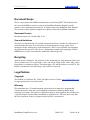
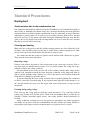
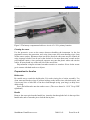
L IN DORM . COM
Lindorm Inc.
SediMeter User Manual
final draft
SEDIMETER USER MANUAL.DOC
2008-11-01
PAGE 1 OF 40
L IN DORM . COM
Lindorm Inc.
Document Scope
This is a user manual for SediMeter instruments, model family SM2. The document does
not cover the SediMeter software (refer to the SediMeter Software Manual), nor file
formats, serial communication protocols, or similar (refer to the SediMeter Tech Manual).
The sections on the LogDator computer are equally valid for the LogDator instrument.
Document Version
Document version 1.0.2, dated 2008-11-01.
Use and limitations
This device is intended only for scientific and professional use, whether in a laboratory or
in nature under the water. It uses and may emit radio frequency energy, and it is not
designed or tested with regard to radio interference. The user is responsible for mitigating
any problems that may arise. The device is furthermore exempt from complying with the
RoHS directive, and it is not lead free, traditional solder being used.
Recycling
Apart from the electronics, the materials of the instrument are polycarbonate (black and
clear), stainless steel 316 (equivalent to A4), and silicon filling in the sensor. The yellow
finger knob is an unknown plastic. The holder tube is PC and the anchor screw SS316. The
handle is aluminium in the 6060 range, with an SS316 cotter pin.
Legal Notices
Copyright
This manual is ©Lindorm, Inc., 2008. All rights reserved. Contact [email protected]
to request permission to use the material.
Warranty
The instrument has a 12-month warranty against defects in material or workmanship.
Contact the factory or the place you bought the instrument to obtain an RMA before
returning it for repairs. No express or implied warranty is made regarding the usefulness for
a specific purpose, beyond what is mandated by applicable law. The user must verify that
the device performs in the way required by the specific circumstances.
SEDIMETER USER MANUAL.DOC
2008-11-01
PAGE 2 OF 40
L IN DORM . COM
Lindorm Inc.
Contents
DOCUMENT SCOPE ................................................................................................................................................. 2
Document Version ............................................................................................................................................ 2
Use and limitations........................................................................................................................................... 2
LEGAL NOTICES ..................................................................................................................................................... 2
Copyright .......................................................................................................................................................... 2
Warranty........................................................................................................................................................... 2
OVERVIEW OF PARTS ........................................................................................................................................ 5
STANDARD PROCEDURES................................................................................................................................. 7
DEPLOYMENT ......................................................................................................................................................... 7
Cleaning and sealing........................................................................................................................................ 7
Preparation for the dive................................................................................................................................. 10
Under water procedures ................................................................................................................................ 12
Post-dive procedures...................................................................................................................................... 14
TEMPORARY RETRIEVAL FOR GETTING DATA AND OR REPLACING BATTERIES .................................................. 15
Preparation..................................................................................................................................................... 15
Diver procedures............................................................................................................................................ 15
Opening and data capture ............................................................................................................................. 15
RETRIEVING AT END OF MISSION ......................................................................................................................... 17
Preparation..................................................................................................................................................... 17
Diver procedures............................................................................................................................................ 17
Opening and data capture ............................................................................................................................. 18
Post-deployment procedures.......................................................................................................................... 18
USER INTERFACE............................................................................................................................................... 19
NAVPIN OPERATION............................................................................................................................................. 19
Menu overview ............................................................................................................................................... 19
LogDator ........................................................................................................................................................ 20
Mode ............................................................................................................................................................... 20
Date UTC........................................................................................................................................................ 20
Time UTC ....................................................................................................................................................... 20
Interval............................................................................................................................................................ 20
Next At ............................................................................................................................................................ 21
Store On.......................................................................................................................................................... 21
Memory ........................................................................................................................................................... 21
USB .................................................................................................................. Error! Bookmark not defined.
RS485.............................................................................................................................................................. 21
RS485 ID......................................................................................................................................................... 21
Display............................................................................................................................................................ 22
STANDARD OPERATING PROCEDURES..................................................................................................... 23
GUIDE ................................................................................................................................................................... 23
SERIAL COMMUNICATION............................................................................................................................. 27
RS-485............................................................................................................................................................. 27
USB ................................................................................................................................................................. 27
OPERATING MODES.......................................................................................................................................... 28
SELECTING OPERATING MODE ............................................................................................................................. 28
RS485 Mode.................................................................................................................................................... 29
Logging Mode................................................................................................................................................. 29
SEDIMETER USER MANUAL.DOC
2008-11-01
PAGE 3 OF 40
L IN DORM . COM
Lindorm Inc.
Sleep Mode ..................................................................................................................................................... 29
USER INTERFACE SPECIAL OPERATION MODES ................................................................................................. 29
USB ................................................................................................................................................................. 29
Display and NavPin ....................................................................................................................................... 30
SPECIFICATIONS................................................................................................................................................ 31
DIMENSIONS AND WEIGHTS ................................................................................................................................. 31
CURRENT USE AND BATTERY LIFETIME ESTIMATE.............................................................................................. 31
MEMORY CARD FUNCTIONALITY .............................................................................................................. 33
INSERTION ............................................................................................................................................................ 33
FILE CREATION ..................................................................................................................................................... 33
MEMORY CARD SELECTION ................................................................................................................................ 33
EXCHANGING MEMORY CARD DURING LOGGING ................................................................................................ 34
SETTING UP AN RS-485 NETWORK .............................................................................................................. 35
CONSIDERATIONS................................................................................................................................................. 35
CALIBRATION ..................................................................................................................................................... 37
OPTIMIZING TURBIDITY ACCURACY........................................................................................................ 38
APPENDIX: THE SI SYSTEM............................................................................................................................ 39
SEDIMETER USER MANUAL.DOC
2008-11-01
PAGE 4 OF 40
L IN DORM . COM
Lindorm Inc.
Overview of Parts
Figure 1. The main parts. The handle tube is now anodized yellow and the bar in blue.
Figure 2. The logic unit of the SediMeter™, the LogDator™. The printed circuit board
(PCB) under the front panel is exposed for illustration only; in normal use the front panel
SEDIMETER USER MANUAL.DOC
2008-11-01
PAGE 5 OF 40
L IN DORM . COM
Lindorm Inc.
should never be removed. The user interface consists of the NavPin (a tact switch with 4
directions plus select), the display, and the Reset button. Using a thin object the Reset
button is accessible through the opening in the front panel. The display can be used with or
without backlight. The switch for turning backlight on and off is located almost under the
black cap of the NavPin (it is the closer one in the double switch; the farther one is for RS485 termination). The USB and memory card slot are accessed from the end through panel
openings. If RS-485 UW contacts are installed they are connected using the indicated RS485 PCB connector. If optional sensors are installed they are connected via cables to the
bottom-left analog part of the LogDator. (“Dator” is Swedish for ‘computer’.)
SEDIMETER USER MANUAL.DOC
2008-11-01
PAGE 6 OF 40
L IN DORM . COM
Lindorm Inc.
Standard Procedures
Deployment
Avoid moisture due to the condensation risk
Pay attention to the humidity when servicing the SediMeter to avoid condensation inside it
after closing it. Although you should always use a moisture-absorbing desiccant inside the
instrument house to protect against condensation, keep the following in mind: When the
instrument is getting colder (as in cold seas or in winter), the dew point will be reached
unless the air was very dry and/or cold when closing the instrument. In many cases the dew
point is only a few degrees below the air temperature out at sea. Unless the sea is warmer
than the air you will need a desiccant.
Cleaning and sealing
Make sure the o-ring grooves and the cylinder mating surfaces are clean. Especially look
for fibers, since any fiber, such as a tiny hair or a fiber from a cloth or a paper towel, when
placed across the o-ring will break the seal and allow water to enter.
Also make sure that the o-rings are greased on all surfaces with a thin layer of grease.
There must be no dry spot whatsoever.
Removing o-rings
If there is dirt in the o-ring groove, if the o-ring needs to get a new layer of grease, if the oring show signs of damage such as cracks, or if it is time to replace the o-ring due to age,
proceed to remove the o-ring as follows.
Put your thumb on the o-ring on one side of the cylinder, and the index finger on the
opposite side, and push towards the same direction so that the o-ring bulges up from its
groove. Gently push the bulge sideways so it leaves the groove, and continue along both
sides until it is completely out of the groove.
If you are removing the lower o-ring you must roll it over the LogDator. Be careful not
to slide it, especially over the display or any exposed metal edge that could damage it. As
an extra precaution one may cover the logger with some clean plastic, or tape over the
metal parts.
Cleaning and greasing o-rings
First clean out the o-ring grooves, then the o-rings themselves. Use a lint-free cloth to
gently wipe off dust, dirt, and old grease. Work in an environment that is as dust-free as
possible. Clothes, household paper towels, and windy beaches should absolutely be
avoided.
Apply a thin but covering coat of o-ring grease by spreading it out with your fingers
(use single use gloves for even less contamination risk, plus it keeps you clean). Pull the oring between your fingers several revolutions until every spot for sure is covered.
SEDIMETER USER MANUAL.DOC
2008-11-01
PAGE 7 OF 40
L IN DORM . COM
Lindorm Inc.
Replacing o-rings
Make sure that the o-ring groove and the surrounding surfaces are clean and—most
importantly—free from fibers. Place the o-ring into the groove on one side and push it with
your fingers along both sides so it slides in completely.
To replace the o-ring in the lower end, under the LogDator, first clean very carefully the
entire length of the LogDator house. Be careful not to wet the display when cleaning,
though. Use a moist lint-free wipe to clean off any dust and fibers. Then roll the o-ring
down the cylinder and place it in its groove. Finally you may want to remove traces of oring grease left behind, to avoid that it attracts dirt. (It may be easier to just cover the logger
with clean plastics, taped in place.)
Desiccant
When the SediMeter’s LogDator has been prepared and set up, the final step before closing
the lid is to place a bag of desiccant inside. The reason is that there is a certain amount of
humidity in the air that will be trapped, and if the instrument gets cooled down sufficiently,
that humidity will condensate, which may cause malfunction.
Figure 3. When closing the lid, after making sure the o-ring and its groove and mating
surfaces are clean and the o-ring is greased, push it in until it makes resistance. At that time
give it a twist to easily get the o-ring into the cylinder without risking harm to the o-ring (a
red o-ring is used on the photos for clarity; the real o-ring is black).
Closing the lid
It does not matter if you first place the top lid on the cylinder and then the cylinder on the
SediMeter itself, or if you do it in the opposite order. In any case you may find that the lid
SEDIMETER USER MANUAL.DOC
2008-11-01
PAGE 8 OF 40
L IN DORM . COM
Lindorm Inc.
wants to come off as a result of the pressure inside the cylinder. This is a good sign, since it
shows that the o-rings are sealing.
Figure 4. Closing the spring.
Hold the lid down while you swing the locking spring in place (Fig. 4). Push on the bend of
the spring to make it mate with the groove on the lid. Some springs, when they are new,
may need a little bit of help in opening up around the cylinder. Make sure it slips into the
groove all the way around. Finally check that the ends of the spring are not coming out of
their holes. If they are, push them back in (the bend should be within a mm or two from the
plastic).
The purpose of the spring
The purpose of the spring is just to hold the lid in place on land. As soon as the SediMeter
gets under water the water pressure will hold the lid in place.
SEDIMETER USER MANUAL.DOC
2008-11-01
PAGE 9 OF 40
L IN DORM . COM
Lindorm Inc.
Figure 5. The battery compartment holds two size AA 3.6 V Li primary batteries.
Cleaning the sensor
Use the protective cover on the sensor whenever handling the instrument. As the last
preparation remove the protection, and, using clean water and a non-abrading wipe, clean
off the sensor surface. Substances that can not be dissolved with water may be cleaned off
using isopropyl alcohol, but do not let the alcohol sit for more than some seconds on the
polycarbonate surface, since prolonged exposure may turn the plastic white and ruin the
sensor. If in any doubt, try on the rear side of the sensor first.
Polycarbonate is impact resistant, but rather sensitive to scratches. Never let the sensor
get in contact with hard surfaces or objects.
Preparation for the dive
Holder tube
Be careful not to scratch the holder tube. If it needs rinsing do so before assembly. Use
clean water and lint-free wipes. If salt has built up on the inside, rinse with fresh water, and
if necessary blow a little ball of lint-free cloth through (using your lungs) to help loose
debris along.
Screw the holder tube onto the anchor screw. (The screw thread is 11/16” 24 tpi UNF
right hand.)
Handle
Remove the cotter pin from the handle bar, insert the bar through the hole in the top of the
handle tube, and re-insert the pin to lock the bar in place.
SEDIMETER USER MANUAL.DOC
2008-11-01
PAGE 10 OF 40
L IN DORM . COM
Lindorm Inc.
Figure 6. Turn the cotter pin sideways as in this photo to get it in and out while inside the
handle tube. Once in place turn it back perpendicularly so it will stay safely in place.
Marking insertion depth
Place the SediMeter, outer tube, and handle next to each other and aligned the way they
interact (Fig. 7). Decide how deep you want to insert the SediMeter in the bottom. If you
expect sedimentation you may want to leave just 2 or 3 detectors buried, and if you expect
erosion you may want to leave all but 7 or 8 detectors buried. Remember that the top 6 ones
are used for estimating turbidity.
Figure 7. Lined up for measuring insertion depth on the handle tube.
Place a mark on the handle tube at your required insertion depth. We suggest using
electrical (vinyl) tape for a temporary mark. You can also make a permanent mark with a
marker on the anodized tube.
Buoyancy
It is more convenient to handle objects on the bottom, such as the SediMeter, if they are
heavier than water. You may want to check that the SediMeter really has negative
buoyancy, and if that is not the case, tape some ballast inside it or on its top end.
Diver considerations
It is easier to screw the anchor into the bottom if the diver can maintain negative buoyancy
at the bottom. We recommend at least a couple of kg of negative buoyancy with empty
SEDIMETER USER MANUAL.DOC
2008-11-01
PAGE 11 OF 40
L IN DORM . COM
Lindorm Inc.
buoyancy vest or dry suit. The heavier the better, but keep in mind the safety, and the
capacity of the vest or suit.
It is also possible to deploy the SediMeter by snorkeling, in shallow waters. Count on
making several dives to screw the anchor all the way down. Unless you have neutral or
negative buoyancy you have to swim downwards while screwing, which is difficult but not
impossible. We recommend a weight belt for neutral buoyancy, or better, negative
buoyancy in combination with a safety vest and a flotation device at the surface for resting.
Under water procedures
Carrying the SediMeter
You need to bring 3 things to the bottom: The SediMeter instrument itself, the outer tube
with anchor screw, and the handle (Fig. 8). If it has to be brought by one person in one
dive, there are two options: placing the SediMeter inside the outer tube, or placing the
handle outside the outer tube. In the first case, make sure the SediMeter does not float up.
In the second case, carry the handle upside down so the anchor tube does not fall out.
Check for leaks
Check the instrument house for leaks while descending, and especially immediately it is
dipped in the water. If it leaks immediately return to the surface, open it, remove the
batteries, pour out all water. First rinse with fresh (preferably distilled) water to drive out
the salt, then rinse with alcohol (e.g. isopropyl 99%) to drive out the water. Finally drive
out the alcohol; if you use a blow dryer make sure no component is heated to above 50ºC.
SEDIMETER USER MANUAL.DOC
2008-11-01
PAGE 12 OF 40
L IN DORM . COM
Lindorm Inc.
Figure 8. The SediMeter with holder and handle ready for deployment.
Screwing down the holder tube CCW
Note that the anchor screw operates counterclockwise, as it has a left hand thread.
Place the handle over the outer tube, so that the bayonet connects to the stainless steel
pins on the anchor (Fig. 9). Place vertically on the bottom and screw down CCW until the
pre-determined depth.
SEDIMETER USER MANUAL.DOC
2008-11-01
PAGE 13 OF 40
L IN DORM . COM
Lindorm Inc.
Rotate the handle slightly clockwise to disengage the bayonet, and pull straight up.
Take care not to pull at an angle, since doing so might scratch the surface of the
polycarbonate holder tube.
Figure 9. A bayonet connects the handle to the anchor screw. It does not lock in place, so if
transporting them together while swimming, hold the anchor screw upwards to prevent it
from falling out. (Note: Newer handles are anodized yellow for better corrosion protection.)
Placing the instrument in the holder
Pick up the SediMeter and hold it vertically. Carefully slide the SediMeter into the holder
tube. Make sure it does not scratch at the entrance. When it is down all the way, so the
outer tube is about 2 cm into the end of the SediMeter, tighten the yellow finger screw until
the SediMeter is no longer loose (lift it to test). Do not over tighten, as that will break the
outer tube.
Post-dive procedures
Rinsing the handle
Disassemble the handle in its 3 components and rinse in fresh water. Rinse especially
carefully inside the tube, since any salt accumulation there risks scratching the holder tube.
After removing all traces of salt dry the tube (push or blow a cloth through the tube to dry it
inside), and store it in a dry place.
Note that the cotter pin is stainless steel. To prevent galvanic corrosion it should not be
left in the aluminium cross bar unless both components are absolutely dry and free of salt.
For maximum protection do not assemble the parts for storage.
SEDIMETER USER MANUAL.DOC
2008-11-01
PAGE 14 OF 40
L IN DORM . COM
Lindorm Inc.
Temporary retrieval for getting data and or replacing
batteries
Preparation
Bring fresh water for rinsing, and lint-free towels. It is recommended to cap the tube while
the SediMeter is gone, both because the transparent tube is very hard to see, and to prevent
dirt from getting in. A black or yellow cap or plastic bolt is recommended (the colour
depending on the colour of the bottom). The tube has 20 mm outside diameter, 16 mm
inside. Another tip is to use the handle as a marker.
Diver procedures
When reaching the SediMeter we recommend recording the bottom level and taking a
photo, to serve as ground truth.
Loosen the finger screw, carefully remove the SediMeter, and cap the tube with the
marker (or the handle).
Opening and data capture
When the SediMeter is back above the surface it should be rinsed in fresh water, and the
instrument house dried. Never let salt water dry on the sensor! If possible use compressed
air to blow away some of the water sitting under the cylinder but outside the o-rings. A lintfree cloth can also be used to get the water out by capillary action.
Figure 10. To open, push on the spring’s corners.
SEDIMETER USER MANUAL.DOC
2008-11-01
PAGE 15 OF 40
L IN DORM . COM
Lindorm Inc.
It is best to let a non-diving and thus dry person open the SediMeter. If that is not
possible you should dry your hair and face so you will not drip, then rinse your hands with
fresh water and dry them.
When both the hands and the SediMeter are salt free and dry, open the spring. Hold the
cylinder with both hands and push on the bends of the spring with your thumbs (Fig. 10).
To download data or change memory card, it is enough to remove the top plug. To
change batteries you must remove the cylinder, too.
Changing batteries
Use the NavPin to switch from Log mode to Sleep mode (to prevent that a measurement
takes place without batteries installed, since that may drive down the voltage so much that a
reset results). The mode may be changed by approaching a magnet to the reed switch,
before opening the instrument, on units so equipped. Make sure the display is off, and
especially so if the display backlight is on.
In this situation you have several minutes of backup power available in a capacitor.
Exchange the batteries to new 3.6 V AA batteries, with the minus pole towards the spring.
(If other battery types become available in the future, any size AA battery capable of
delivering at least 15 mA at 3 V < U < 4.5 V can be used.)
USB data download
Switch to Sleep mode if not already done, using the NavPin. Connect the USB cable
between the LogDator and the computer. Start the SediMeter software and Connect.
Download the data using the Download tab. Get the SediMeter settings using the Setup tab.
Check the clock error and take a note for reference. Enter a new start time for resuming
logging and click Set. Switch back to Log mode in the Special tab. Disconnect in the
Connection tab. Remove the USB cable and proceed to close the SediMeter.
For further instructions refer to the SediMeter Software Manual.
RS-485 data download
Although not originally intended for downloads, it is possible to download data over the
RS-485 serial communication link. You do need a contact and cable, though, and it is rather
slow (9600 baud).
Note that if the instrument has an UW connector, and an UW cable is available, data
may be downloaded without retrieving the instrument. The diver would instead connect the
cable, change the SediMeter to RS485 mode using the magnetic switch, and when the
download was complete disconnect the cable again. Otherwise the procedure is the same as
below.
Connect an RS-485 cable between the LogDator and the computer. Switch to RS485
mode using the NavPin or the magnetic switch. Start the SediMeter software and click
Connect. Download the data using the Download tab. Get the SediMeter settings using the
Setup tab. Check the clock error and take a note for reference. Enter a new start time for
resuming logging and click Set. Switch back to Log mode in the Special tab. An error
message appears saying that no reply came; that is because the mode change cut off the
SEDIMETER USER MANUAL.DOC
2008-11-01
PAGE 16 OF 40
L IN DORM . COM
Lindorm Inc.
connection. Disconnect in the Connection tab (to free the serial port). Remove the cable and
replace the dummy to protect the connector.
For further instructions refer to the SediMeter Software Manual.
Memory card exchange
Switch to Sleep mode if not already done, using the NavPin or the magnetic switch.
Remove the MMC or SD card by pressing it in until you feel a click that releases it.
Remove it, and put in the new one. Check the display (it may take several seconds for the
card to be mounted).
If the display reads “MMC Card Mounted” all is well and you may proceed (it will say
“MMC” even if it is an SD card, that is perfectly normal and not an error).
On the other hand, if the display says “MMC Card Error XX” where XX is a two digit
hexadecimal number, the card is not mounted. You may want to try again, sometimes it
works after several attempts. If not, try with another card. Refer to the error codes for
further debugging. (Hint: Code 80 means that it cannot communicate at all, i.e., it is a nonsupported card. Code 08 means that it cannot read the partition table, which may be
because the card is not formatted in FAT16, in which case it must be formatted in a
computer. However, code 08 may also appear if the card was not reset properly, so you
may want to remove it, wait a few seconds, and try again, or even press the SediMeter reset
button with the card in place, since that resets also works for the card and the built-in
memory chip.)
If nothing happens after 5 s with an SD card, check that the write protect slide is not
engaged. If it is, the LogDator™ will not detect the card.
Each time a card is inserted (or the SediMeter is reset with a card in place) a new *.ld2
file is created in its root folder. The file name is constructed as follows: Two digits for the
year, one for the month (with range 0–B), two for the day, and three digits for the file
number on that date (000–999). The files can not be erased in the SediMeter, and they have
the read-only flag set to prevent inadvertent modification in a computer. The modified date
shows the last time data was written to the file.
If all is well proceed to set a new start time using the NavPin (since some measurement
may have been lost while you changed the card). Finally switch back to Log Mode and turn
off the display. Proceed to close the SediMeter.
Retrieving at end of mission
Preparation
Bring fresh water for rinsing, and lint-free towels. Assemble the handle.
Diver procedures
When reaching the SediMeter put away the handle temporarily on the sea floor. You may
want to record the bottom level relative the sensor and take a close-up photo.
SEDIMETER USER MANUAL.DOC
2008-11-01
PAGE 17 OF 40
L IN DORM . COM
Lindorm Inc.
To protect the tube from scratches in the active measurement zone when forcing the
handle down to the anchor, first make a depression to the depth of the lowermost detector.
Use hands or flippers.
Loosen the finger screw, remove the SediMeter and leave it in a safe place. Push down
the handle, twisting it right and left while pushing until it reaches the anchor and connects
to the bayonet. Screw the anchor up clockwise.
If the anchor is shallow and the sediments are soft, you may also be able to pull it up
gently by the holder tube. You can safely twist clockwise without risking unscrewing the
tube, since the holder tube has got a clockwise thread, and the anchor a counterclockwise
thread.
Opening and data capture
Use the same method described above for retrieving data.
Post-deployment procedures
Rinse and dry all components. Remove batteries. Insert desiccant and close the SediMeter.
Clean the handle as described above. Clean the holder tube carefully if it will be reused. If it is scratched beyond repair, discard it. Rinse the anchor from sand and mud and
let dry.
A note on scratches
Large scratches that are shiny in the bottom are not so much a concern, since they will not
reflect much light. Remember that they get filled with water and become almost invisible
once submerged. The concern is the small and white scratches that will trap air under water.
It is theoretically possible to polish tiny scratches (such as those left by polishing with a
very fine sand paper) by warming the surface with a hot air gun. Polycarbonate (PC) melts
at over 120ºC. However, it absorbs moisture, and when it reaches 100ºC the water starts
boiling, creating vapor bubbles in the plastic – unless it is dried first. The drying procedure
is incompatible with the sensor, but the holder tube might be salvageable.
If the PC material is not dried, a hot air gun can still be used to remove the finest
scratches but the exposure time must be kept to seconds. The creation of bubbles goes very
quickly, it destroys the product permanently, and the method should never be attempted
except as the absolutely last resort. The method requires a lot of practice, but even with
practice it is very risky. It is better to accept one or two bad detectors than to try polishing
and risk ruining the entire sensor.
SEDIMETER USER MANUAL.DOC
2008-11-01
PAGE 18 OF 40
L IN DORM . COM
Lindorm Inc.
User Interface
Different versions of SediMeters may be operated either by using a built in user interface
with a control stick called NavPin, or by software connected either through USB or RS485.
The SediMeter has a built-in real-time clock that is programmed to keep track of time in
UTC (similar to GMT it is the time at the 0 meridian). This eliminates the need to keep
track of time zones and seasonal time changes (daylight savings time, summer time). When
setting the time from a computer, the clock is automatically set to within ca 0.02 seconds.
Just remember that when setting the start time of measurements, one must set that too in
UTC.
Figure 3. Operation of the NavPin. It may also be operated with the cylinder in place (use a
finger if your thumb does not fit). The backlight is on in this photo, but in most cases it may
be preferable to leave it off to save power.
NavPin operation
The NavPin can be tilted in four directions (up, down, left, right) and pressed straight down
(select). Left or down changes the menu in one direction, right or up changes it in the
opposite direction. Select enters edit mode, which is indicated visually by the presence of a
cursor. Left and right moves the cursor between the fields that can be edited in that
particular menu. Up and down changes the value. Select (i.e., pressing down) exits edit
mode with the presently indicated values.
Menu overview
The menu system is shown in the following table:
SEDIMETER USER MANUAL.DOC
2008-11-01
PAGE 19 OF 40
L IN DORM . COM
Lindorm Inc.
LogDator
SM2 v1.4
(turns
off)
Mode
RS485
ON
Log Mode
Date UTC
20071231
Time UTC
14:56:01
Interval
00:01:00
Next At
00:02:00
Store On
Internal
Memory
2MBflash
Samples
(opt) 84
RS485
9600 bps
RS485 ID
Set: 001
Display
Turn Off
(set date)
(set time)
(set)
(set)
MMC
Card
MarkRead
(set
count)
*
Set ID
(turns off)
Sleep
EraseAll
*At present only one baud rate is supported, why any attempt to change the value will result in the same value being shown again.
The NavPin user interface can be used to prepare the SediMeter for stand-alone
measurements. This eliminates the need for a computer in the field, thus making it possible
to prepare for measurements even on a small, open diving boat. If an MMC card is used for
storing data, retrieving data can also be done using a low-cost vessel. (Note that the rate
and count of optional analog sensor samples cannot be set using NavPin in v1.0.)
The individual menus and their operation are described in the following.
LogDator
Selecting turns off the display. All other clicks switches to another menu.
Mode
Switch between RS485 mode for real-time monitoring controlled by a remote computer,
Log Mode for self timed monitoring, and Sleep Mode in which only the real-time clock
remains active. Using Sleep Mode the SediMeter may be synchronized with a PC at the
office, transported to the field, and then prepared using the NavPin with measurement time
and interval. As the final step, select Log Mode.
Magnetic switch
The reed switch (beyond the display, opposite the serial number sticker) cycles through this
menu. The switch is operated by approaching a strong magnet to the instrument. Each time
the value changes the display is turned on for a short moment as visual feedback.
Date UTC
The date in UTC. Click select to enter edit mode, click left or right to chose value to edit,
click up and down to edit the value, and click select to stop editing. The cursor blinks in the
field that is active for editing.
Time UTC
The time in UTC. Click select to enter edit mode, click left or right to chose value to edit,
click up and down to edit the value, and click select to stop editing. The cursor blinks in the
field that is active for editing.
Interval
Selects the interval between measurements in hours:minutes:seconds. At present it only
accepts even minutes.
SEDIMETER USER MANUAL.DOC
2008-11-01
PAGE 20 OF 40
L IN DORM . COM
Lindorm Inc.
Next At
Selects the time of the next measurement (in the same time zone as the clock).
Store On
Selects the memory to use for data storage, Internal or MMC Card.
Supported cards include standard MMC, high speed MMC, RS-MMC with a holder, and
standard SD with 2.1 mm thickness. MMC cards are 1.4 mm thick and have no notch; SD
cards have a notch on the side with a diagonal corner. The following are not supported:
standard SD with 1.4 mm thickness, SDHC (high capacity; all SD with more than 2 GB are
SDHC). Note that if a SD card has the tab set in the Lock position, the SediMeter will not
detect its presence.
The memory card will increase the power consumption. As a general rule faster cards, and
cards with a higher capacity, draw more current. A large card will use up the battery long
before the memory gets full. The advice is therefore to use a small and old card if possible,
until such a time as the manufacturers begin to pay more attention to the need for lowpower low-capacity memory for data logging purposes.
Memory
This menu allows two operations that are not possible to do from the PC.
First, it allows the RRP (Read Record Pointer) to be set equal to the WRP (Write Record
Pointer), by selecting MarkRead. This is useful if the memory was already read, but got
marked as unread by a system reset.
Secondly, it allows all records in the flash memory to be erased. Normally the memory is
used in a round-robin fashion, so as to use all pages equally and not wear out the beginning
(there is a limit to how many times flash memory can be used, and certain applications
might exceed that limit for the first page if not using a round-robin scheme). To erase all
requires the user to first select EraseAll, and then confirm it by shifting from Erase? N to
Erase? Y, and finally clicking select. The erasing takes ca 20 seconds. Check the real time
clock after erasing the memory as it may have been affected.
Samples
For each measurement, the optional sensors can be sampled up to 84 times. Set the count in
this menu. Set to 0 if no optional sensors are present, since it conserves battery power.
RS485
RS-485 baud rate. The only choice is 9600 baud.
RS485 ID
The RS-485 network ID (called NetAddr in the computer software) can be changed here. If
more than one SediMeter is on the same network, they must have unique IDs. The ID is a
SEDIMETER USER MANUAL.DOC
2008-11-01
PAGE 21 OF 40
L IN DORM . COM
Lindorm Inc.
value from 1 to 255. Each SediMeter has a pre-programmed ID. Only in the unlikely event
that two SediMeters with the same ID happen to be on the same network must one of them
have its ID changed. It can be changed either using this menu, or the PC software. The
changed value is stored in RAM, so after each reset the ID returns to the default value. (The
RAM retains its values down to 1.8 V, so two alkaline batteries can be used as a safety
precaution in case RS485 power is lost.)
Display
Selecting turns off the display. All other clicks switches to another menu.
SEDIMETER USER MANUAL.DOC
2008-11-01
PAGE 22 OF 40
L IN DORM . COM
Lindorm Inc.
Standard Operating Procedures
Guide
1.
Using the NavPin user interface ................................................................................2
Using a computer (whether RS-485 or USB).............................................................6
2.
Deployment ..............................................................................................................3
Retrieving data and/or changing battery ..................................................................19
End-of mission retrieving........................................................................................30
3.
Install batteries. Press Reset. Observe number of free records. If sufficient,
jump to......................................................................................................................5
Display reads NO free records, or an insufficient value less than 4096 ......................4
4.
Repeatedly click right on the NavPin to get to menu “Memory”. Click select
to enter edit mode, and click up until “MarkRead” appears on the second line.
Click select to execute. The text changes to “MarkedOK” when done. Click
any direction to return to the text “2MBflash”. Click select to again enter edit
mode, and up twice to show “EraseAll”. Click select and it responds with
“ERASE? N”. Click up or down and the last letter changes to “ERASE? Y”.
Click select. All records will now be erased, a process that takes in the order
of a minute or more to execute. When done the second line will read
“Erased”. Click right or left until you get to either the “LogDator” menu or
the “Display Turn Off” menu. Clicking select in either of those turns the
display off. Press Reset again. Observe the value, it should be 4096. Value
OK............................................................................................................................5
5.
Set Date, Time, Next (start of measurements), Interval (time between
measurements), and Samples (optional sensors). All times are in 24-hour
format. The first measurement will take place when the clock reaches the
Next time, provided that Log Mode is active. If the deployment is more than
24 hours into the future, select Sleep (mode), otherwise select Log Mode. ................7
6.
Set up the LogDator following instructions in the SediMeter Software Manual .........7
7.
If you plan to use an MMC card, install it, make sure the display says “MMC
Card Mounted”, and select Store On MMC Card (using the NavPin).........................8
8.
If the SediMeter is buoyant, a small ballast may be used in the house (e.g., a
small bag with nuts). The required amount is in the order of tens of grams
rather than hundreds of grams. ..................................................................................9
9.
Make sure both o-rings are clean and are completely covered by a thin layer
of grease. Examine closely to make sure there are no fibers, threads, or hair
on the o-rings, in the grooves, or on the cylinder’s seating surface. Assemble
SEDIMETER USER MANUAL.DOC
2008-11-01
PAGE 23 OF 40
L IN DORM . COM
Lindorm Inc.
the house and close the spring. Inspect the o-ring seals around the cylinder
making sure they are in contact with the cylinder. Bring carefully into the
water while looking at the o-ring seals, checking for any sign of water leaking
into the house. While descending towards the bottom, keep checking for signs
of water leakage. If no leakage is detected...............................................................10
If water is entering, hold the instrument so the water accumulates in a spot
away from the PCB while returning to the surface. Proceed with emergency
operations ..............................................................................................................39
10.
Deploying in sediments using the anchor and holder tube .......................................11
Deploying on hard bottoms upside down.................................................................17
11.
Screw the holder tube onto the stainless steel anchor. Put the handle bar
through the hole on the handle tube and secure it with the cotter pin. Attach
the handle to the anchor over the tube. Hold the SediMeter next to it, and put
on a tape or similar on the handle to mark the desired depth of insertion into
the bottom. Pass the SediMeter and the handle-holder assembly to a diver or
snorkeler already in the water. ................................................................................12
12.
Dive to the bottom. If the SediMeter is properly ballasted, it can be “parked”
on the bottom with the probe pointing up, thus freeing up both hands. ....................13
13.
Screw down the anchor to the indicated depth by turning counterclockwise,
keeping it vertical. Turn the handle clockwise some 10º – 20º. Lift it straight
up until it is free from the holder. ............................................................................15
15.
Insert the SediMeter probe carefully into the holder all the way. Secure it with
the yellow finger screw (do not over tighten) ..........................................................16
16.
Return the handle to the surface, disassemble, and rinse off the components
inside and outside with fresh water. Let it dry before storing ..............................END
17.
Drill a hole with diameter ca 55 mm, and at least 34 cm deep .................................18
18.
Insert the SediMeter (without yellow finger-knob), instrument first, into the
hole, and place ballast (e.g., a donut-shaped weight) to hold it in place ...............END
19.
Loosen the yellow finger-knob, pull out the SediMeter and bring to the
surface. Note 1: Since the holder tube is very hard to see without the
SediMeter in it, it is recommended to use some kind of marker in the
meantime. It could be as simple as a white plastic bolt inserted into the
transparent tube, perhaps with a white plastic strip attached to it. This also
prevents debris from falling into the tube. Note 2: Make sure not to disturb
the bottom around the SediMeter if a continuous measurement record is
desired. It is much easier for a SCUBA diver to maneuver precisely, using a
buoyancy vest, than it is when snorkeling................................................................20
SEDIMETER USER MANUAL.DOC
2008-11-01
PAGE 24 OF 40
L IN DORM . COM
Lindorm Inc.
20.
If possible, rinse the instrument with fresh water and blow to remove most
drops from around the O-rings. If using something to dry it with, make sure it
does not abrade the plastic, and that it does not leave fibers on the surface. .............21
21.
Un-snap the spring lock. To replace batteries ..........................................................23
To exchange memory card only ..............................................................................24
23.
Remove the cylinder and the upper plug. Use the NavPin to switch to Sleep
mode (or the magnetic switch). Replace the batteries. .............................................25
24.
Remove the upper plug. .........................................................................................25
25.
Press the memory card in so it clicks and ejects. Pull it out. Put in a new
memory card, pushing it in so far that it clicks and locks in place. Verify that
the display reads MMC Card Mounted ...................................................................26
If the display reads MMC Card Error followed by an error code, or nothing............27
26.
Using the NavPin, go to the Store On menu and change to MMC Card. ..................28
27.
Try again a few times, then reformat the card as FAT16. If nothing helps, use
another card. (If no reply for an SD card, check the write protection) ......................25
28.
Check the O-rings, assemble, and descend as per step 9. ........................................29
29.
Insert the SediMeter probe carefully into the holder all the way. Secure it with
the yellow finger screw. Be careful not to disturb the bottom near the
instrument if a continuous measurement series is desired. ..................................END
30.
If the screw anchor is used, assemble the handle and descend to the
SediMeter. If you desire to re-use the holder tube....................................................31
If the holder tube will not be re-used .......................................................................32
31.
Using the hands or fins to create turbulence, make a depression around the
instrument that exposes all the reflex detectors on the SediMeter, and a few
centimeters more.....................................................................................................32
32.
Loosen the yellow finger screw and remove the SediMeter instrument from
the holder tube. .......................................................................................................33
33.
Slide the handle over the holder tube, and push it down through the sediments
while turning it alternately clockwise and counter-clockwise to help it get
down. When the bayonet is reached, rotate it until you feel that the bayonet
lines up, push it down hard, and turn clockwise.......................................................34
34.
Screw the anchor up clockwise. When it is quite close to the surface you may
lift it straight up (do not use excessive force, but unscrew it until it no longer
makes resistance before pulling)..............................................................................35
35.
Bring the SediMeter to the surface. Rinse both the instrument and the handle
in fresh water .........................................................................................................36
36.
Disassemble and dry the handle as per point 16 ......................................................37
SEDIMETER USER MANUAL.DOC
2008-11-01
PAGE 25 OF 40
L IN DORM . COM
Lindorm Inc.
37.
Dry the instrument and open it. To retrieve data, connect a USB cable (or RS485) and download. Since the USB (or RS-485) supplies power, the batteries
are not required for this operation ...........................................................................38
38.
For short-term storage set in Sleep mode. For longer-term storage, remove the
batteries. ............................................................................................................END
39.
Leakage: open the house, remove the batteries, pour out all water. First rinse
with fresh (preferably distilled) water to drive out the salt, then rinse with
alcohol (e.g. isopropyl 99%) to drive out the water. Finally drive out the
alcohol; carefully wipe off the excess, then consider using a fan. If you use a
blow dryer make sure no component is heated to above 50ºC. Finally let the
device dry completely in a low humidity environment for 48 h before
connecting power again. (Hint: vacuum also helps removing moisture, if you
by any chance have a vacuum chamber big enough.) If it does not work after
this treatment contact the manufacturer ...............................................................END
SEDIMETER USER MANUAL.DOC
2008-11-01
PAGE 26 OF 40
L IN DORM . COM
Lindorm Inc.
Serial communication
Both protocols may be used with the SediMeter software, with the recommended method in
bold as follows:
Use
RS-485
USB
Set up self-timed logging
Yes
Yes
Download recorded data
Yes (but 100 times slower
Yes
than USB)
Logging while connected
Yes when only physically
Yes (but a temperature bias
connected
is introduced if using the
No when communication is
standard sensor)
established
Real-time measurements
Yes
Yes (but a temperature bias
is introduced if using the
standard sensor)
RS-485
For RS-485 to be operational, the SediMeter must be in RS485 mode. After a Reset it
automatically enters RS485 mode. Once it has been set in sleep mode or logging mode, it
can only be returned to RS485 mode by (1) a Reset, (2) by using the magnetic switch, (3)
through the NavPin user interface, or (4) by issuing commands through USB. For an
instrument under water, only methods 1 and 2 work. For method 1, the power must be cut
long enough for a Reset to take place (it means that the instrument must not have batteries
installed). For method 2, a diver must approach the magnet to the instrument.
Self-timed measurements are suppressed while in RS485 mode (but externally ordered
real-time measurements can be made, using command N). If the computer does not have
RS-485 built in, an adapter from USB to RS-485 may be used.
USB
Measurements can be made while the USB is connected. However, be aware that while in
USB mode the CPU is running on a much higher clock frequency, which warms up the
computer so that the temperature reading from the standard sensor no longer is reliable. It
will show the computer temperature, not the ambient temperature. (In normal use as a
logger the duty cycle of the computer is so low, and constant from measurement to
measurement, that the sensor for all intents and purposes shows the ambient temperature.)
SEDIMETER USER MANUAL.DOC
2008-11-01
PAGE 27 OF 40
L IN DORM . COM
Lindorm Inc.
Operating Modes
The device has one inactive mode, and two operating modes: a stand-alone Log Mode, and
a remote mode in which it is controlled through RS-485. The operating mode can be set
using the built-in user interface, the magnetic switch, or by serial communication
commands. After a Reset the device is in RS485 Mode.
An Excel sheet is available for estimating battery and memory use,
http://lindorm.com/downloads/batteryuse.xls. Some values when using the internal memory
are given below. When using an MMC or SD card there is virtually no limit on how much
data can be stored, but the rather high battery consumption of the card becomes the limiting
factor. It is recommended to use as small a card as possible (and at any rate not a high
density card since they are not supported), and as slow a card as possible, since smaller and
slower use less battery.
Mode
Self-Timed
Measurements
Remote
Measurements
Current drain in Battery
rest
Life†
RS485
No
Yes
830 µA
102 days*
Log
Yes
No
32 µA**
4 years
Sleep
No
No
32 µA**
4.25 years
† Battery life is calculated based on 7560 C (2.1 Ah) useable capacity and one
measurement per hour without any optional sensors. Note that the internal memory will get
full after only 170 days at this measurement rate.
* In RS485 mode the power would typically be supplied through the cable. The battery life
is the life absent such supply.
** This value is excluding any memory card.
Selecting operating mode
RS485 is selected for remote operation. The real-time clock, interval, or start time, are not
used to trigger measurements. Instead measurements are triggered by commands over the
network. These may be either broadcast to all instruments, or sent to a specific instrument.
The only setting that is still used is the interval between analog measurements. For fastest
response, especially if no analog sensors are present, set 0.
For self-timed logging set to Log Mode. Also set date, time, interval, and start time. Data
can be stored either internally or on a memory card (MMC or SD). The data are transferred
to a computer by moving the card to a computer, and opening the *.ld2 file using the
SediMeter software.
If the internal memory is used the recorded data can be transferred to a computer through
USB (or RS-485, but it is much slower: 40 minutes to download the entire memory).
SEDIMETER USER MANUAL.DOC
2008-11-01
PAGE 28 OF 40
L IN DORM . COM
Lindorm Inc.
The instrument can also be set in Sleep mode in which neither logging nor remote operation
is possible. Settings are still retained, and the real time clock remains running. This mode
may be used when transporting the instrument or storing it for shorter periods.
RS485 Mode
In this mode the device is functioning as a remote-controlled instrument without internal
data logging. It is the default mode after Reset. The instrument is listening to RS-485
communication. It is not performing any self-triggered measurements regardless of the
logging interval and start time settings. It performs a measurement only when instructed to
do so by the N command (for New measurement). The data is not stored on flash memory
but instead transferred to a RAM buffer, from where the RS-485 master can request it using
the P command (for Previous measurement). The computer will send an N as a broadcast,
wait until the SediMeters are finished, then send a P to retrieve the data from one
SediMeter at a time.
Log Mode
In this mode the device is a stand-alone instrument with an internal clock, and a logger that
stores measurement data either on a built-in 2 MB flash memory, or on a MMC or SD Card
that may be up to two gigabyte in size. The data is retrieved by removing the card and
plugging that into a computer.
When the SediMeter is in Log Mode, the Time for Next Measurement is updated as part of
each measurement, so that it always shows the time of the next measurement. If the
SediMeter is not in Log Mode, the Time for Next Measurement does not change.
Sleep Mode
This mode can be used for transportation and temporary storage (for long term storage the
battery should be removed; a Reset will occur when it is powered up again). It can be
woken up using the NavPin, through USB, or even by pressing the Reset button.
User Interface Special Operation Modes
USB
The LogDator will automatically detect USB insertion regardless of which mode is set. The
USB chip is powered from the computer. When in the USB state the LogDator switches
from the internal oscillator on the MPU, to an external 3.6 Mhz crystal. This increases the
power demand also for components not supplied by the computer. Therefore, either
disconnect the USB whenever it is not needed, or remove the batteries.
The higher velocity and continuously running system clock leads to that the MPU
warms up more. The temperature measurements may therefore be too high for a while after
disconnecting USB.
As the USB uses the same serial port as the SediMeter probe, measurements will
conflict with USB.
SEDIMETER USER MANUAL.DOC
2008-11-01
PAGE 29 OF 40
L IN DORM . COM
Lindorm Inc.
Display and NavPin
The LCD without backlight is rather low on power, and using it for a few minutes will not
have any appreciable effect on the battery lifetime. However, for every second the
backlight is on, it draws the same amount of power as one measurement does.
The display backlight is turned on and off using the switch immediately above the
NavPin (#2 on the dual switch; #1 is for RS-485 termination).
SEDIMETER USER MANUAL.DOC
2008-11-01
PAGE 30 OF 40
L IN DORM . COM
Lindorm Inc.
Specifications
Dimensions and weights
Length overall
700 mm
House diameter
51 mm
Sensor length
510 mm
Sensor diameter
15 mm
Volume
ca 0.4 L
Mass (as deployed)
ca 0.4 kg
Buoyancy
Nearly neutral
Current use and battery lifetime estimate
If you are unfamiliar with the SI units refer to the appendix.
Batteries
2 size AA 3.6 V Li batteries
Battery Capacity
Qbattery ! 7560 C (2100 mAh)
Current, idle, sleep and log modes Iidle ! 32 µA
Current during burst sampling
Depends on sensors, up to 15 mA
Current, idle, RS485 mode
Iidle ! 830 µA
Discharge per measurement
!measurement ! 15 mC
Drain in MMC/SD card, idle
126 µA " I " 213 µA (based on 3 cards: 128 MB
standard MMC, 128 MB fast MMC, 1 GB standard SD)
Discharge per record written
! 1 mC for internal flash, ! 0.1 mC for memory cards
The following formula can be used to estimate the battery requirement for a give time and
number of measurements:
!mission = Iidle · t + !measurement · n
where
!mission is electrical the discharge of the entire mission in coulomb (C)
Iidle is idle current in ampere (A)
t is time in seconds (s)
!measurement is discharge per measurement in coulomb (C), and
n is number of measurements (the unit is 1).
SEDIMETER USER MANUAL.DOC
2008-11-01
PAGE 31 OF 40
L IN DORM . COM
Lindorm Inc.
If ! mission " Qbattery the battery has sufficient capacity. Suitable batteries include SAFT
LS14500, and Tadiran TL-5104. This battery type works well in cold weather, and is more
adversely affected by a hot climate. The values are for 25ºC.
If also considering the self-discharge of 10% annually, the following missions are all near
the edge of the possible. The assumption in all cases is that 2700 mAh batteries are used,
and if optional sensors are present they are only samples once (not in an extended burst).
A. Internal memory, measurement interval 12 hours, mission duration 4.5 years
B. Memory card 64 MB, measurement interval 6 minutes, mission duration 1 year
C. Memory card 128 MB, measurement interval 1 minute, mission duration 6 months
D. Memory card 256 MB, measurement interval 5 seconds, mission duration 30 days
Due to the high idle current of memory cards, any card with higher capacity than 256 MB
will exhaust the battery before the memory is full, even at the most extreme measurement
rate. The recommendation is to use as small a card as possible, and the old standard speed
of MMC rather than the new high speed, since capacity and speed are the two factors that
seem to increase the idle current. Contrary to in many other fields, old cards are thus
preferable. (Unfortunately there is currently no development pressure to lower the power
consumption in these cards, nor do the manufacturers make those data available to the
buyers.)
When planning a mission always leave some margin on the batteries. It is better to
replace half empty batteries than to have them run out halfway through the deployment.
These values may help to give you an idea:
It would take over 600,000 measurements to empty the batteries if the idle current was
zero (corresponding to ca 300 MB in storage space).
The idle current and self-discharge together will empty the batteries in about 5 years
even if no measurements are made, i.e., in sleep mode (if there was no self-discharge they
would last for over 9 years).
You may also download an Excel spreadsheet for estimating optimal mission settings,
http://lindorm.com/downloads/batteryuse.xls
SEDIMETER USER MANUAL.DOC
2008-11-01
PAGE 32 OF 40
L IN DORM . COM
Lindorm Inc.
Memory Card Functionality
MMC cards MMCplus cards, and SD cards can be used and have been tested. RS-MMC,
MMCmobile, and MMCmicro are expected to work with the appropriate adapter, since
they differ only in size from the former, but they have not been tested. The card must be
formatted in the FAT16 file system (this may also be called FAT in formatting software).
Note that SDHD cards (high density SD) are not supported.
Insertion
When the card is inserted an interrupt is hardware generated to the MPU. The CPU will
wake up, and shall establish communication with the MMC card. An error code is reported
on the display if something goes wrong. If everything goes well the display reports that the
card is mounted.
File creation
Each time the card is inserted a new file is created on the first free sector. Multiple
insertions and removals thus blocks a number of sectors, by creating directory entries
although no data is actually written. These 0-sized files can be deleted in a computer, but
not in the LogDator itself.
The name of the file reflects the time of creation, with the month represented as one
hexadecimal character in the range 1 to C. The file name is thus YYMDDXXX.sd2 where
XXX is a number updated for each new file created the same day.
The date and time in the directory entry reflects the last modification of the file.
Note that if the card is in the holder during a Reset a new file will be created. Since the
Reset sets the date and time to 2007-12-31 00:00:00, the file name will be 07C31000.ld2,
the modification date as the creation date, and the size zero (0). To get a file with correct
date in the name, take out the card before resetting the LogDator, and set at least the date
before re-inserting the card.
Memory Card Selection
As default the LogDator records data on the internal memory. Use the NavPin to switch
from “Internal” to “MMC Card” (this also covers SD cards). If no MMC or SD card is
mounted when the NavPin is depressed for selection, it automatically switches back to
“Internal”. The same happens if the card is removed during logging (although you should
turn Log Mode off before removing the card, to avoid the risk that you remove the card
while it is recording data).
SEDIMETER USER MANUAL.DOC
2008-11-01
PAGE 33 OF 40
L IN DORM . COM
Lindorm Inc.
Exchanging memory card during logging
•
Switch to Sleep mode using the NavPin (if a measurement is in progress the display
may be unresponsive for up to 166 s [83 sample intervals / 0.5 Hz], while burst
samples are being collected).
•
Remove the old card.
•
Insert the new card and check that the display says “MMC Card Mounted”.
•
Check that the time of next measurement is in the future (i.e., that the clock did not
pass the next time while you switched cards). If necessary, change the Next time.
•
Switch back to Log Mode.
SEDIMETER USER MANUAL.DOC
2008-11-01
PAGE 34 OF 40
L IN DORM . COM
Lindorm Inc.
Setting up an RS-485 Network
Considerations
The computer must have an RS-485 serial port. A USB to RS-485 adapter may be used.
One pair in a twisted pair cable is used for the signals, A and B. One of the two is
normally-positive, the other normally-negative. Unfortunately a majority of manufacturers
have A and B opposite to the standard, why a trial and error approach may be necessary if
an unfamiliar port device is used.
The second twisted pair (or straight wires) may be used for power supply to the SediMeter.
This is not necessary, but considering the high power demand of the SediMeter in RS485
mode (which it needs to be in to allow communication by RS-485), in most cases it is
clearly preferable. If the cable is long and many instruments are connected, calculate to
make sure that a thick enough wire is used (AWG in the US).
Most power for the measurements are provided by an internal super-capacitor. It is charged
up slowly through an internal current-limiting resistor (R6, the only hole-mounted resistor).
If the cable itself has a significant resistance, one can short R6 to limit the voltage drop and
permit faster re-charge times. (A diode prevents current from flowing out from the supercapacitor, so each instrument depends on its own capacitor.)
RS-485 network topology is a daisy chain, with all units connected along a single cable that
may be up to 1200 m long with full speed, 1 million baud. Typically the computer would be
in one end, with a long cable to the first SediMeter, and short cables connecting the
following SediMeters to each other. However, another possibility is to have the computer in
the middle, with the two cable ends going out in different directions to two clusters of
SediMeters on the same network.
In high-speed communication the signal out may have shifted from high to low or vice
versa before the previous signal has returned as an echo from the end of the cable (its
velocity is ca 200 Mm/s). In such cases termination is necessary. The termination consists
of a resistor across the A-B pair, at each end of the cable. There should be no termination
on the intermediate SediMeters (or the computer, if that is in the middle).
The termination resistors short, through 120 ", the signal wires in each end. This of course
increases the power demand for driving them. Furthermore, the idle lines should have a
certain voltage potential between them. To maintain that difference, biasing resistors are
needed, which increases the power demand also in idle.
The LogDator has pads for a termination resistor (R22, size 0805, resistance 120 "). It also
has a switch, above the NavPin, for turning termination on and off.
However, at the currently only supported baud rate of 9600 baud, the echoes are long since
gone before the receiver samples the line, with a 1200 m cable. The line is sampled half-
SEDIMETER USER MANUAL.DOC
2008-11-01
PAGE 35 OF 40
L IN DORM . COM
Lindorm Inc.
way in the bit; i.e., 52 µs after switching level, in 9600 baud. During that time the signal
will travel 10400 m, that is, to the end and back in a 5.2 km long cable.
The conclusion is that termination is not required for 1200 m cable lengths (the longest
permitted in the standard), why no termination resistor is installed on the PC board. If a
future version supports an optional higher baud rate (such as 115,200 baud) then the
termination will be required.
Note that with 9600 baud it takes over 0.5 s to download each record. In the largest possible
network, 255 SediMeters, it will therefore take well over 2 minutes to download all the data
from one measurement. This limits the possible measurement frequency (the time for
collecting the data, which they do simultaneously, must be added, plus a few milliseconds
for ordering the measurement). The reason for introducing 115,200 baud as an option
would be to increase the possible measurement frequency.
Regarding the number of SediMeters in the network, the RS-485 standard defines load
units, and specifies that only 32 load units may be on the network at any one time.
However, the chip used in the SediMeter only has a load of 1/8th load unit, why 32 x 8 =
256 units can be on the network. One of those being the computer, it leaves 255
SediMeters. That is also the number of available addresses (NetAddr, RS485 ID).
However, for this to be true also the computer must have a load of 1/8th load unit. If the
computer uses a standard 1 load unit RS-485 serial port, then “only” 256 – 32 = 224
SediMeters may be on the network.
SEDIMETER USER MANUAL.DOC
2008-11-01
PAGE 36 OF 40
L IN DORM . COM
Lindorm Inc.
Calibration
How to calibrate the SediMeter sensor
Note that the calibration is different depending on if the holder tube is used or not. If you
deploy the instrument both with and without, do two separate calibrations.
1. Deploy the sensor in a tube with 10 cm pure water in front of the sensor (within 90º
of the axis of measurement)
2. Block out ambient light (especially NIR light)
3. Carry out a measurement
4. Record the Uon values in V from each detector (in the analysis graph)
5. Also check the Uoff values from each of the 6 zones
6. Enter Uon values as U0 in column A in the calibration window of the software
7. Enter Uoff (normally near 0) as D
8. Use B=1.386 and C=0.202
9. Prepare a Formazin suspension in the vessel (use at least 100 FTU without holder
tube, and preferably 1000 FTU or more with holder tube)
10. Carry out a measurement
11. Record the RAW values in V from each detector (in the analysis graph)
12. Calculate K = C / RAW (where K is the conversion factor with units FBU/V, and C
is the concentration in FTU)
13. Enter the K values in the calibration table and save the calibrations
You are now ready to use the calibrations. As a test, you may leave the SediMeter
measuring how the Formazin settles. It will take a few hours to start seeing the process.
Theory
The data from the sensor are translated to FTU values called FBU, for Formazin
Backscatter Units, using the equation shown in the box. It takes the background light into
account in the form of a second-degree equation, Uadj. The background light is measured
virtually simultaneously with the backscatter, so as to account for the very fast order-ofmagnitude fluctuations that are present when sunlight shines through waves in shallow,
tropical waters. In fact, the procedure is to measure the background, the backscatter, the
background again, and to interpolate the two background values to estimate the value at the
same millisecond when the backscatter was measured.
While the units may correctly be labeled FTU, the use of the SediMeter unit FBU is more
specific since it shows that the measurement was made with 945 nm light, 180° backscatter,
and with compensation for the contemporary ambient light according to this method. The
ambient light is measured after a black filter that only allows NIR light to pass. Since NIR
SEDIMETER USER MANUAL.DOC
2008-11-01
PAGE 37 OF 40
L IN DORM . COM
Lindorm Inc.
is attenuated very quickly in water, even quicker than red light, and the LED emits a strong
strobe, ambient light is only a factor in the first couple of meters in tropical waters, and
perhaps the first meter in extra-tropical waters. However, by introducing this procedure to
compensate for it, the SediMeter can be used close to the surface even in daytime.
It should be noted that if FBU = kFTU (U on " U 0 " U adj )
the ambient light is
where
strong enough, it may
2
saturate the detectors. If U adj = B(U amb ) " C (U amb ) = adjustment for U amb
they are nearly but not
U amb = U off " U dark is the ambient light
quite saturated, low
turbidity levels may still U 0 = U on when FTU = 0, in water with no reflectors
be possible to measure,
U dark = U off in darkness
but not high turbidity
U on & U off are reported by the SediMeter
(since background light
kFTU is a proportionality constant determined in darkness
and reflected light is
added in the signal).
Calibrations values in the software (for each OBS unless noted) :
The effect in the
K = kFTU
software analysis
A = U0
window may be that
correct values are
B # 1.386
reported in the water,
C # 0.202
but invalid data is
D = U dark (one value for each of the 6 zones)
shown below the
bottom. This allows the user to at least estimate the water turbidity and a maximum bed
elevation, but not the exact bed elevation or a minimum for it. This compromise was
deemed acceptable in order to increase the turbidity resolution. (It is possible to change the
! resistors A0 to A5 – contact the factory if the need arises.)
range by replacing
Optimizing Turbidity Accuracy
Turbidity accuracy after calibration when using a polycarbonate outer tube is ca ±100 FBU
(most of the uncertainty stems from variations in reflections on the inner surface of the
outer tube).
For turbidity profile measurements it is recommended to mount the instrument in some
other way. One possibility is to mount it upside down, burying the logger house in the sea
floor so that only the sensor sticks up. That will also create the least drag. It should be
noted, though, that the instrument must be calibrated specifically for this mounting method.
It is possible to use a separate calibration file for use with and without outer tube (and for
an acrylic outer tube instead of a polycarbonate one; the acrylic gives lower noise but is
much more fragile).
SEDIMETER USER MANUAL.DOC
2008-11-01
PAGE 38 OF 40
L IN DORM . COM
Lindorm Inc.
Appendix: The SI system
Quantity
Time
Length
Mass
Temperature
Luminous
intensity
Amount of
matter
Electrical
current
Solid angle
Force
Pressure
Energy, work
Effect (=power)
Radiant
intensity
Irradiance
Radiance
Luminous flux
Illumination
Luminance
Frequency
Electrical
potential
(~difference)
Electrical
charge (~flow)
Capacitance
Resistance
Volume
Volume,
auxiliary unit
Symbol
t
l
m
T
I
Unit
second
meter
kilogram
kelvin
candela
Symbol
s
m
kg
K
cd
Definition
Base Unit
Base Unit
Base Unit
Base Unit
Base Unit
n
mole
mol
Base Unit
I
ampere
A
Base Unit
"
F
p
E, W, etc.
P
steradian
newton
pascal
joule
watt
sr
N
Pa
J
W
W·sr-1
1 N = 1 kg·m·s-2
1 Pa = 1 N·m-2
1 J = 1 N·m
1 W = 1 J·s-1
#
E
lumen
lux
f
V (U)
hertz
volt
W·m-2
W·m-2·sr-1
lm
lx
cd·sr-1
Hz
V
Q (!)
coulomb
C
1 C = 1 A·s
C
R
V
V
farad
ohm
cubic meter
liter
F
"
m3
L
1 F = 1 C·V-1
1 " = 1 V·A-1
1 lm = 1 cd·sr
1 lx = 1 lm·m-2
1 Hz = 1 s-1
1 V = 1 W·A-1
1 L = 10-3 m3 =
1 dm3
There are often different ways to express the same quantity, e.g. 1 J = 1 VC = 1 VAs = 1
Ws = 1/3600 Wh; or, 1000 mAh = 1 Ah = 3600 As = 3600 C; or, 1 dm3 = 1 L = 0.001 m3.
SEDIMETER USER MANUAL.DOC
2008-11-01
PAGE 39 OF 40
L IN DORM . COM
Lindorm Inc.
Multiple prefixes
Factor
1012
109
106
103
102
101
100
10-1
10-2
10-3
10-6
10-9
10-12
Prefix
Name
tera
giga
mega
kilo
hekto
deka
—
deci
centi
milli
micro
nano
pico
Prefix
Symbol
T
G
M
k
h
da
—
d
c
m
µ
n
p
Notes
If and only if the prefix is larger than kilo is it written with a capital letter.
The symbol unit never takes a plural s. Correct: kg. Incorrect: Kgs
Use exponents for complex units. Recommended: kg·m-1·s-2. Never write kg/m/s2
Use a space between value and unit. Correct: 12 V. Incorrect: 12V
SEDIMETER USER MANUAL.DOC
2008-11-01
PAGE 40 OF 40


![[PDF:0.6MB]](http://vs1.manualzilla.com/store/data/005664304_1-5124c75bfbffa9dc3657cce05bb0013f-150x150.png)