1
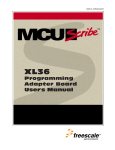
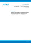
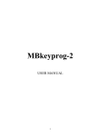
Freescale Semiconductor, Inc...
Freescale Semiconductor, Inc.
AT60
Programming
Adapter Board
User's Manual
For More Information On This Product,
Go to: www.freescale.com
Freescale Semiconductor, Inc...
Freescale Semiconductor, Inc.
Document Edition
Date
M68AT60PABUM/D
September 1998
Motorola reserves the right to make changes without further notice to any
products herein to improve reliability, function, or design. Motorola does not
assume any liability arising out of the application or use of any product or circuit
described herein; neither does it convey any license under its patent rights nor
the rights of others. Motorola products are not designed, intended, or
authorized for use as components in systems intended for surgical implant into
the body, or other applications intended to support or sustain life, or for any
other application in which the failure of the Motorola product could create a
situation where personal injury or death may occur. Should Buyer purchase or
use Motorola products for any such unintended or unauthorized application,
Buyer shall indemnify and hold Motorola and its officers, employees,
subsidiaries, affiliates, and distributors harmless against all claims, costs,
damages, and expenses, and reasonable attorney fees arising out of, directly
or indirectly, any claim of personal injury or death associated with such
unintended or unauthorized use, even if such claim alleges that Motorola was
negligent regarding the design or manufacture of the part.
Motorola and the Motorola logo are registered trademarks of Motorola Inc.
MCUscribe is a trademark of Motorola Inc. Windows is a registered trademark
of Microsoft Corporation. Windows NT and Windows 95 are trademarks of
Microsoft Corporation. Adobe and Acrobat Reader are trademarks of Adobe
Systems Incorporated. All other trademarks are the property of their respective
holders.
Motorola Inc. is an Equal Opportunity/Affirmative Action Employer.
© 1998 by Motorola, Inc. All Rights Reserved.
Motorola
6501 William Cannon Drive West
Austin, Texas 78735 USA
2
AT60Product,
Programming Adapter Board User’s Manual
For More Information On This
Go to: www.freescale.com
Freescale Semiconductor, Inc...
Freescale Semiconductor, Inc.
Contents
1
Getting Started
1.1
2
Installing the MCUscribe Application and Personality Files
1.1.1
Installed Files 6
1.1.2
Installing Acrobat Reader 7
1.2
Inserting AT60 Programming Adapter Boards
1.3
Disconnecting Power Before Handling Components
1.4
Inserting AT60 MCUs
6
7
8
9
1.4.1
Inserting a QFP MCU 9
1.4.2
Inserting a PLCC MCU 10
Using the AT60 and Its Supported Devices
2.1
AT60 Devices and Mask Sets
12
2.2
MCU Memory Configuration 13
2.2.1
AS60 MCU Memory
13
2.2.2
AZ60 MCU Memory
14
2.2.3
QA24 MCU Memory
15
AT60 Programming Adapter Board User’s
ManualInformation On This Product,
For More
Go to: www.freescale.com
3
Freescale Semiconductor, Inc.
CONTENTS
2.3
16
Support
3.1
Opening Additional Online Documentation
3.2
Contacting Customer Support
19
20
Freescale Semiconductor, Inc...
3
Special Warnings
4
AT60 Programming Adapter Board User’s Manual
For More Information On This Product,
Go to: www.freescale.com
Freescale Semiconductor, Inc...
Freescale Semiconductor, Inc.
Getting Started
T
Who needs to read this manual?
Users of the M68PA08AT60 (AT60) programming adapter board (PAB)
and AT60-supported microcontroller units (MCUs) should read this
manual for information about:
• Installing software and setting up the AT60 programming adapter board
for use
• Operation instructions specific to AT60-supported MCUs
• Getting additional support
This chapter explains how to install the software that comes with your
AT60 PAB, and how to plug in the PAB and the MCUs it supports.
AT60 Programming Adapter Board User’s
Manual
For More
Information On This Product,
Go to: www.freescale.com
5
Freescale Semiconductor, Inc.
GETTING STARTED
1.1 Installing the MCUscribe Application and Personality Files
The AT60 PAB comes with the latest version of the MCUscribe application
(for Windows NT and Windows 95). First, install the software:
Freescale Semiconductor, Inc...
Insert the first MCUscribe diskette in your floppy drive, and enter
a:\setup.exe in the Windows Run dialog box. The installation setup
program opens.
Follow the instructions to install the software into a folder of your choice.
The installation program places all the MCUscribe files in one folder. Using
a single folder expedites selection of the MCU and S-record files, so that you
can start programming more quickly.
1.1.1 Installed Files
The setup program installs these files on your system:
• MCUscribe.exe — Windows executable file for the MCUscribe
application—the interface you use to communicate with the SPGMR08,
and to program MCU memory.
• .mmp files — The personality files that supply the SPGMR08 with MCU
configuration and memory map information. The personality files for
AT60-supported MCUs are 908qa24.mmp, At60as.mmp, and
At60az.mmp.
• MCUscribe.hlp and MCUscribe.cnt — Online help for using the
MCUscribe application.
• MCUscribe.pdf — Serial Programmer for HC08 User’s Manual.
Instructions for using the MCUscribe application (help information
presented in an Acrobat-format user’s manual).
• QStart08.pdf — SPGMR08 QuickStart Guide. A streamlined guide
(in Acrobat format) to setting up SPGMR08 hardware and software.
• PABAT60.pdf — This a PDF version of the AT60 Programming Adapter
Board User’s Manual, with specific instructions for setting up and using
the AT60 PAB (may also include user manuals for other PABs).
• AX48modification.pdf — Modifying the AX48 Programming Adapter
Board. An engineering bulletin on modifying the AX48 PAB for use with
QA24, AZ60, and AS60 MCUs.
• readme.txt — Release notes in ASCII format (text from QStart08.pdf)
For tips about opening online support documents, see page 19.
6
AT60Product,
Programming Adapter Board User’s Manual
For More Information On This
Go to: www.freescale.com
Freescale Semiconductor, Inc.
GETTING STARTED
1.1.2 Installing Acrobat Reader
Freescale Semiconductor, Inc...
You must have Acrobat Reader installed on your system to view
and print the Serial Programmer for HC08 User’s Manual and other
Acrobat-format support documents. The programming adapter board comes
with the latest version of the Reader, which gives you full support for the
interactive elements in Acrobat-format documents. To install the Reader:
Insert the first Reader diskette in your floppy drive, and enter
a:\setup.exe in the Windows Run dialog box. The installation setup
program opens. Follow the instructions to install the software into a folder of
your choice.
1.2 Inserting AT60 Programming Adapter Boards
To use the AT60 programming adapter board, plug the PAB onto the
SPGMR08 base unit (as shown in the illustration below). The PAB works
when installed in either direction on the SPGMR08 base unit. That is, the
connector on the base unit labeled Pin 1 can accept either connector of the
adapter board.
QFP device
socket case,
with lid closed
PLCC device socket
AT60 programming
adapter board
Pin 1
SPGMR08
base unit
AT60 Programming Adapter Board User’s
Manual
For More
Information On This Product,
Go to: www.freescale.com
7
Freescale Semiconductor, Inc.
GETTING STARTED
1.3 Disconnecting Power Before Handling Components
Freescale Semiconductor, Inc...
If power is disconnected, you can insert or remove MCUs and programming
adapter boards freely. However, if you are in an MCUscribe session, make
sure the yellow Socket Power light is off before you handle the MCU or
switch out the programming adapter board. MCUs can be damaged by power
surges during installation.
If the Socket Power light is on, click the Power Off button in the MCUscribe
Control Panel. Socket power is disconnected, and the yellow Socket Power
light goes off.
8
AT60Product,
Programming Adapter Board User’s Manual
For More Information On This
Go to: www.freescale.com
Freescale Semiconductor, Inc.
GETTING STARTED
1.4 Inserting AT60 MCUs
1.4.1 Inserting a QFP MCU
The illustration below shows a Quad Flat Pack (QFP) MCU ready to be
inserted in the programming adapter board:
Freescale Semiconductor, Inc...
1 Open the socket case by lifting the latch.
2 Insert the MCU, matching the MCU’s Pin 1 with the socket’s Pin 1. The
marked corner of the MCU identifies the location of Pin 1. (The printed
number 1 on the back side of the programming adapter board corresponds
to the location of the socket’s Pin 1.)
Note: Motorola recommends that you use a vacuum pen or other
appropriate tool to handle MCUs. Be careful to avoid
bending the pins.
3 Push the socket lid down gently until it snaps shut.
Pin 1 is located at the MCU’s marked
corner. (The marked corner has either a
recessed dot or a clipped edge.)
A printed diagram in the
upper left corner of the
board shows the location
of the QFP Pin 1.
socket latch
AT60 Programming Adapter Board User’s
Manual
For More
Information On This Product,
Go to: www.freescale.com
9
Freescale Semiconductor, Inc.
GETTING STARTED
1.4.2 Inserting a PLCC MCU
The illustration below shows a Plastic Leaded Chip Carrier (PLCC) MCU
ready to be inserted in the programming adapter board:
Freescale Semiconductor, Inc...
Insert the MCU, with the pins facing up, matching the MCU’s Pin 1 with
the socket’s Pin 1. A recessed dot near the MCU’s edge identifies the
location of Pin 1. The PLCC socket’s Pin 1 is marked on the board as
PIN 1 n PLCC.
Caution: If you attempt to program an AS60 or QA24 PLCC MCU
inserted with the pins facing down, you can damage the
device. Make sure you insert AS60 and QA24 PLCC
MCUs with the pins facing up.
The MCU’s Pin 1 marker is a small recessed
dot near the edge of the chip.
(Insert the device so that the printed Motorola
logo and device name face down.)
The MCU’s clipped corner should be in
the upper right (when you view the PAB
right-reading, as shown).
The PLCC socket’s Pin 1 is marked
on the board as PIN 1 n PLCC.
As noted on the AT60 board,
you must Insert PLCC Pins UP.
Note: Motorola recommends that you use a vacuum pen or other
appropriate tool to handle MCUs. Be careful to avoid bending
the pins.
10
AT60Product,
Programming Adapter Board User’s Manual
For More Information On This
Go to: www.freescale.com
Freescale Semiconductor, Inc...
Freescale Semiconductor, Inc.
Using the AT60 and
Its Supported Devices
This chapter has specific information about using the AT60 programming
adapter board and the devices it supports. The AT60 PAB enables the
SPGMR08 to program:
• Flash EEPROM and EEPROM memory ranges of MC68HC908AS60
(AS60) MCUs in 52-pin Plastic Leaded Chip Carrier (PLCC) package
configurations.
• Flash EEPROM and EEPROM memory ranges of MC68HC908QA24
(QA24) MCUs in 52-pin Plastic Leaded Chip Carrier (PLCC) package
configurations.
• Flash EEPROM and EEPROM memory ranges of MC68HC908AZ60
(AZ60) MCUs in 64-pin Quad Flat Pack (QFP) package configurations.
Notes:
The generic term AT60 (also seen in earlier documentation)
appears on AS60 and AZ60 MCUs. To verify a particular
device as an AS60 or AZ60, check the printed mask set
number, or call your Motorola representative for assistance.
Notes:
For information about using AT60-supported MCUs with the
M68PA08AX48FNFU (AX48), see the engineering bulletin
“Modifying the AX48 Programming Adapter Board”
(AX48modification.pdf). (Use the red-outlined link above to
jump to the bulletin only if you are viewing this manual with
Acrobat Reader version 3.01 or later.)
If you need information about other AT60-supported packages,
contact Motorola customer support (see page 20).
AT60 Programming Adapter Board User’s
Manual
For More
Information On This Product,
Go to: www.freescale.com
11
Freescale Semiconductor, Inc.
USING AT60 PROGRAMMING ADAPTER BOARDS
Freescale Semiconductor, Inc...
2.1 AT60 Devices and Mask Sets
Selected MCU/Mask Choice
Device
Mask Set
Personality File
MC68HC908AS60
4H62A; 8H62A
At60as.mmp
AT60AS;
8H62A
MC68HC908AZ60
3H62A; 8H62A
At60az.mmp
AT60AZ;
8H62A
MC68HC908QA24
2J98H
908qa24.mmp
908QA4;
2J98H
The table above lists AT60-supported devices and mask sets, with these
types of corresponding information:
• Personality file — The file that supplies configuration and memory map
data for programming the various AT60-supported MCUs and mask sets.
To program a particular mask set, the corresponding personality file for
that mask set must be installed on the host system.
• Selected MCU/Mask choice — The entry you select during an
MCUscribe session, from the Control Panel’s Selected MCU list
(shown in the illustration below).
12
AT60Product,
Programming Adapter Board User’s Manual
For More Information On This
Go to: www.freescale.com
Freescale Semiconductor, Inc.
USING AT60 PROGRAMMING ADAPTER BOARDS
2.2 MCU Memory Configuration
Freescale Semiconductor, Inc...
2.2.1 AS60 MCU Memory
AS60 MCUs have 60 KB of programmable Flash EEPROM memory, 1 KB
of programmable EEPROM, and 2 bytes of vector memory. The MCUscribe
AS60 Memory Map status box (shown below) displays the location of the
Flash EEPROM and EEPROM memory arrays.
AT60 Programming Adapter Board User’s
Manual
For More
Information On This Product,
Go to: www.freescale.com
13
Freescale Semiconductor, Inc.
USING AT60 PROGRAMMING ADAPTER BOARDS
2.2.2 AZ60 MCU Memory
Freescale Semiconductor, Inc...
AZ60 MCUs have 60 KB of programmable Flash EEPROM memory, 1 KB
of programmable EEPROM, and 2 bytes of vector memory. The MCUscribe
AZ60 Memory Map status box (shown below) displays the location of the
Flash EEPROM and EEPROM memory arrays.
14
AT60Product,
Programming Adapter Board User’s Manual
For More Information On This
Go to: www.freescale.com
Freescale Semiconductor, Inc.
USING AT60 PROGRAMMING ADAPTER BOARDS
2.2.3 QA24 MCU Memory
Freescale Semiconductor, Inc...
The QA24 MCU has 24 KB of programmable Flash EEPROM memory, 512
bytes of programmable EEPROM, 40 bytes of user-definable vector
addresses, and a block protect register.
AT60 Programming Adapter Board User’s
Manual
For More
Information On This Product,
Go to: www.freescale.com
15
Freescale Semiconductor, Inc.
USING AT60 PROGRAMMING ADAPTER BOARDS
2.3 Special Warnings
The following special warnings apply to the AT60 programming adapter
board:
• PLCC device orientation: You can damage any MCU by inserting the
device with an incorrect pin orientation, then attempting to program the
device. With the AS60 PLCC MCU, you must also be careful to insert the
device with the pins facing up.
Freescale Semiconductor, Inc...
Recommendation: Make sure you insert the AS60 and QA24 PLCC
MCUs with the pins facing up, and (as with all devices) make sure you
insert the device so that the MCU’s Pin 1 matches Pin 1 of the socket.
• Electrostatic discharge: Electrostatic discharge can damage the
programming adapter board and the MCUs.
Recommendation: Observe standard grounding precautions to avoid
electrostatic buildup when you handle the programming adapter board
and MCUs.
• Inadvertent Flash EEPROM erasure: If you use a sequence of S-records
to program arrays of Flash EEPROM memory, you may find that each
new programming command erases already-programmed Flash
EEPROM arrays.
Recommendation: Select the appropriate force-erase option for
Flash EEPROM:
Click the Setup button in the Control Panel. The Setup dialog opens.
Select the MCU Programming tab. If the Erase flash before write
check box is checked, click it to clear the check mark.
• With Erase flash before write selected, programming
Flash EEPROM from an S-record erases the entire contents
of Flash EEPROM.
• With Erase flash before write cleared, a programming command
does not erase already-programmed Flash EEPROM arrays.
• Inadvertent enabling of EEPROM security: AS60, AZ60, QA24
MCUs have a special security option that prevents programming and
erasure of EEPROM memory. Be careful not to irreversibly enable this
security feature during a block fill of Flash EEPROM memory.
Recommendation: When you block fill Flash EEPROM memory, make
sure the span of addresses you are programming does not include:
• $FE1C (EENVR1) or $FE18 (EENVR2) for the AS60 and AZ60
• $FE1C (EENVR) for the QA24
16
AT60Product,
Programming Adapter Board User’s Manual
For More Information On This
Go to: www.freescale.com
Freescale Semiconductor, Inc.
USING AT60 PROGRAMMING ADAPTER BOARDS
For more information, see the information about EEPROM security and
EEPROM nonvolatile registers in the General Release Specification.
• Installing multiple devices: If you install more than one device on the
programming adapter board at any one time, the MCUscribe application
is unable to communicate with either device.
Recommendation: Install only one device at a time on the programming
Freescale Semiconductor, Inc...
adapter board.
AT60 Programming Adapter Board User’s
Manual
For More
Information On This Product,
Go to: www.freescale.com
17
Freescale Semiconductor, Inc.
Freescale Semiconductor, Inc...
USING AT60 PROGRAMMING ADAPTER BOARDS
18
AT60Product,
Programming Adapter Board User’s Manual
For More Information On This
Go to: www.freescale.com
Freescale Semiconductor, Inc...
Freescale Semiconductor, Inc.
Support
This chapter explains how to open information resources online,
and how to contact customer support.
3.1 Opening Additional Online Documentation
Acrobat-format documents
The MCUscribe application comes with a user’s manual in Acrobat PDF
format, along with the latest version of the Acrobat Reader. There are a
number of online resources (described on page 6) that you can open from
Windows Explorer by double-clicking the file name:
• Serial Programmer for HC08 User’s Manual — MCUscribe.pdf
(You can also double-click the manual icon in the MCUscribe
program group.)
• The online version of this manual — PABAT60.pdf
• SPGMR08 QuickStart Guide — QStart08.pdf
• Modifying the AX48 Programming Adapter Board —
AX48modification.pdf
AT60 Programming Adapter Board User’s
Manual
For More
Information On This Product,
Go to: www.freescale.com
19
Freescale Semiconductor, Inc.
SUPPORT
Online help
Open MCUscribe help directly from the desktop, or from within the
application. (Make sure you have installed the MCUscribe.hlp file and the
MCUscribe.cnt files in the same folder.) You can use any of these methods
to open MCUscribe help:
Freescale Semiconductor, Inc...
• Double-click the help icon in the MCUscribe program group.
• Double-click the MCUscribe.hlp file in Windows Explorer, if .hlp files
are associated with Winhlp32.exe.
• Click the Help button in the MCUscribe application, or press F1.
3.2 Contacting Customer Support
Contact the Motorola software support team by telephone, FAX,
regular postal mail, or through the World Wide Web.
Telephone: 1-800-521-6274 (Customer Focus Center)
Telephone support hours are Monday through Friday,
9:00 a.m. to 5:00 p.m. (CST).
FAX: (602) 302-8157 (Customer Focus Center)
20
AT60Product,
Programming Adapter Board User’s Manual
For More Information On This
Go to: www.freescale.com
Freescale Semiconductor, Inc...
Freescale Semiconductor, Inc.
AT60 Programming Adapter Board User’s
Manual
For More
Information On This Product,
Go to: www.freescale.com
Freescale Semiconductor, Inc...
Freescale Semiconductor, Inc.
AT60Product,
Programming Adapter Board User’s Manual
For More Information On This
Go to: www.freescale.com