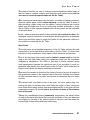
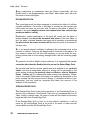
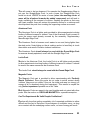
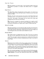
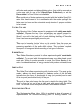
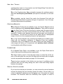
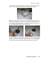
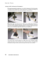
1
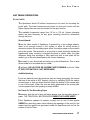
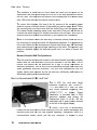
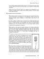
SRP AIR TABLE
TABLE OF CONTENTS
1
SRP AIR TABLE
2 TABLE OF CONTENTS
SRP AIR TABLE
SRP Air Table
USER GUIDE
Version 2.2
Copyright
opyright (c) 1992,1993,1996, 2002, 2007, Andre Michaud
SRP Inc
Tel: 1 (418) 624 0608
Visit our Internet site at http://pages.globetrotter.net/srp/
TABLE OF CONTENTS
3
SRP AIR TABLE
4 TABLE OF CONTENTS
SRP AIR TABLE
TABLE OF CONTENTS
USER MANUAL .......................................................................................... 7
UNPACKING THE AIR TABLE ........................................................................................................... 9
Checklist ............................................................................................................ 9
Minimum Configuration ........................................................................ 9
Additional Options ................................................................................ 9
Unpacking ......................................................................................................... 10
AIR TABLE INSTALLATION .......................................................................................................... 11
Adjustable Legs ................................................................................................. 11
Aluminum Air Head Support ............................................................................ 11
Air Head Assembly............................................................................................ 11
Latex Tubing ........................................................................................ 12
Conducting Chain ............................................................................... 12
Replacement Of Tubes And Chains.................................................. 12
Steel Pucks ........................................................................................................ 12
Air Supply Compressor ..................................................................................... 12
Leveling The Air Table ..................................................................................... 13
Tube And Chain Interference............................................................. 13
Carbon Paper .................................................................................................... 14
Plain Recording Paper ...................................................................................... 14
Newsprint Paper .................................................................................. 15
Rockland Paper ................................................................................... 15
Digital Sparktimer ............................................................................................ 15
Footswitch ............................................................................................ 15
Connecting Cables .............................................................................. 16
AIR TABLE OPERATION .................................................................................................................... 17
Sparktimer ........................................................................................................ 17
Shock Hazard!...................................................................................... 17
Audible Sparking ................................................................................. 17
No Trace On The Recording Paper ................................................... 17
Become Familiar With The Sparktimer............................................. 18
Digital Sparktimer 9 VDC or 9 VAC................................................................. 18
The Pucks .......................................................................................................... 19
General Considerations ..................................................................... 19
Low Frequency Oscillations .............................................................. 19
19
20
OSCILLATIONS AFTER LAUNCH
OSCILLATIONS AFTER COLLISION
Recording Unwanted Oscillations .................................................... 20
Steel Pucks .......................................................................................... 21
ROUND-EDGE PUCK
STRAIGHT-EDGE PUCK
22
22
Aluminum Puck ................................................................................... 23
Lucite Puck .......................................................................................... 23
Magnetic Pucks ................................................................................... 23
TABLE OF CONTENTS
5
SRP AIR TABLE
Can The Experiments Be Valid Despite Oscillations?.................... 23
Edge Pulley ........................................................................................................ 24
Spring Fasteners ................................................................................................ 24
Double-Hooks .................................................................................................... 24
Springs ............................................................................................................... 24
Velcro Collars .................................................................................................... 25
Rubber Bands .................................................................................................... 25
Orbital Post ....................................................................................................... 25
Supplementary Mass ......................................................................................... 25
Circular Magnets ............................................................................................... 26
Paper Guide ....................................................................................................... 26
Manual Puck Launcher .................................................................................... 26
Alternate Puck Shooting Possibility ................................................................... 28
MAINTENANCE AND REPAIR ........................................................................................................... 29
Digital Sparktimer ............................................................................................. 29
Older type 6 frequencies Sparktimer ................................................................. 29
RE-CALIBRATION ................................................................................ 29
SAFETY GAP ........................................................................................ 30
Air Table............................................................................................................ 30
Air Head ............................................................................................................ 30
Conducting Chains ............................................................................................ 31
Latex Tubing ..................................................................................................... 32
Adaptor Voltage and Polarity ............................................................................ 32
ONE YEAR LIMITED WARRANTY ...................................................................................................... 35
6 TABLE OF CONTENTS
USER MANUAL
How to set up and use
the various accessories
of the Air Table
SRP AIR TABLE
UNPACKING THE AIR TABLE
Unpack your Air Table on a flat, stable surface.
CHECKLIST
Check the Air Table package for presence of all material ordered. If any
pieces are missing, contact your retailer.
Minimum Configuration
No matter what configuration of the Air Table was purchased, all items listed
next should have been included:
- 1 Framed Air Table
- 3 Ajustable Legs (Already fitted to the underside of the Air Table)
- 1 Lab Manual
- 1 Aluminum Air Head Support
- 2 Steel Pucks
- 1 Air Supply Head
- 2 Opposing Velcro Collars
- 2 Rubber Bands
- 2 Springs
- 1 Orbital Post
- 4 Removable Spring Fasteners (Small Threaded Posts)
- 1 Supplementary Mass (Approximately 160g)
- 1 Edge Pulley
- 2 Double-Hooks
- 1 Manual Puck Launcher
Additional Options
Most of the times, customers will purchase more than the minimum configuration. The extent and nature of the additional equipment provided in the
various 'Kits' available may vary widely from one retailer to another.
Subject to confirmation by the individual retailer from whom the Air Table was
purchased, any one or more of the following optional accessories may have
been offered as 'Standard' in the specific package or packages offered by that
retailer:
- 2 Circular Magnets
- 1 Special Pucks Set:
- 1 Aluminum Puck
- 1 Lucite Puck
UNPACKING THE AIR TABLE
9
SRP AIR TABLE
- 2 Opposing Magnetic Pucks
- 1 Paper Guide
- Carbon Paper 22" X 22" (4 or more sheets)
- Rockland White Paper (100 or more sheets)
- Newsprint Paper (100 or More Sheets)
- 1 Sparktimer
- 1 Air Compressor
UNPACKING
After opening the top of the Air Table shipping box, remove the top cardboard
separator, The Aluminum Air Head Support, which is usually packaged inside
this separator will come out at the same time.
Pull the framed Air Table strait up out of the box.
Before laying the Air Table on its final resting place, slide both side legs towards the front and let them rest at a distance of about 8 inches from the front
of the Air Table. Slide the back leg to the center of the back side of the Air
Table, right under the aluminum bracket.
Remove the remaining boxed accessories from the Air Table box, thoroughly
checking that nothing is forgotten inside.
The Sparktimer and the Air Compressor will usually have been packaged in
separate boxes.
10
UNPACKING THE AIR TABLE
SRP AIR TABLE
AIR TABLE INSTALLATION
ADJUSTABLE LEGS
The Adjustable Air Table Legs are made of two distinct parts:
- The gray plastic body of the leg
- The white plastic base
Tighten the legs in place to the underside of the table. Each lateral leg should
be positioned at about 8 inches from the front of the Air Table and the rear leg
should be moved to the center of the rear side of the Air Table.
To level the Air Table, simply unscrew and adjust the white plastic base of the
legs to fit your need. The legs can be extended by about 1 inch by
unscrewing the white base.
ALUMINUM AIR HEAD SUPPORT
The end of the longer arm of the Aluminum Air Head Support fits into a tapered hole in the bracket located on the rear side of the air table.
While making sure the shorter arm of the support will end up being centered
over the glass surface of the Air Table, apply a firm twisting pressure to the
support to lock it into the support bracket.
AIR HEAD ASSEMBLY
Unpack the Air Head Assembly from one of the small boxes found in the Air
Table shipping box.
The Air Head Assembly is a delicate piece of equipment and should always
be handled with care.
Before installing, examine the central hole in the middle of the Air Head. You
will notice that the opening is larger on one side than on the other. Insert the
Air Head on the short arm of the Aluminum Support larger opening first.
The holes in the Air Head are designed to fit tightly on the tapered end of the
Aluminum Support when pressure is applied. Holding the Air Head so that the
latex tubes hang freely down, apply pressure carefully while maintaining the
Aluminum Support with your free hand to keep it from bending backwards.
MAINTENANCE AND REPAIR
11
SRP AIR TABLE
The Air Head will give long service if handled with care. The following recommendations concerning the tubes and chains should be carefully understood and heeded.
Latex Tubing
While installing or otherwise handling the Air Head, care must be taken not to
touch unnecessarily the latex tubes, as this material easily reacts chemically
with the natural oils found on the skin. The pure latex material of the tubes
also reacts to ambient ultraviolet light. Exposure to these conditions can
dramatically shorten the useful life of the tubes.
Conducting Chain
Be careful also not to pull on the conducting chains coming out of the latex
tubes. The delicate chain could break or be torn loose from its connection inside the Air Head.
Replacement Of Tubes And Chains
See Section "MAINTENANCE AND REPAIR" on proper procedure to replace
used or broken tubes and chains.
STEEL PUCKS
Unpack the two Steel Pucks (same box as the Air Supply Head) and lay
them on the Air Table.
You will have noticed a clear plastic plug fitted to the loose end of each latex
tube coming from the Air Supply Head. Take one acrylic plug (not the latex
tube) in your hand and after having carefully inserted the chain inside the
wide plastic tube at the center of one of the Steel Pucks, push the plug firmly
in place into the opening of the wide tube.
This operation has been correctly performed if the end of the chain rests
against the metallic part at the bottom of the puck central tube and the plug
sits in such a fashion as to form an airtight seal with the top of the puck
central tube.
Repeat the same operation with the other Steel Puck and remaining plug.
AIR SUPPLY COMPRESSOR
Locate the box containing the Air Compressor and unpack the unit. A length
of plastic tubing should be found in the package.
12
MAINTENANCE AND REPAIR
SRP AIR TABLE
Connect one end of the tube to the exhaust outlet of the compressor and
press the other end of the tube over the input nozzle at the back of the Air
Supply Head.
Connect the compressor to a wall outlet and the Steel Pucks will lift and begin
moving freely over the Air Table.
LEVELING THE AIR TABLE
With the air pressure on, we can now proceed to the leveling of the Air Table.
This operation, quite simple as you will see, is mandatory for proper operation
of the Air Table. Experiments recordings are significant and usable only if the
Air Table is perfectly level.
The leveling guide will be either one of the Steel Pucks.
Put the Steel Puck at the center of the Air Table. If it tends to move on its own
in any given direction, this will indicate that the Air Table is tilted in that
direction,
To correct this condition, unscrew a little the leg that lays in that direction or
screw a little the leg which lays in the opposite direction. Since the Air Table
Legs form a tripod, one will always be located so that adjusting it will have the
greatest effect. Put the puck back in the center and make further adjustments
as necessary.
Perfect leveling will have been achieved when the Steel Puck tends to hover
where you lay it at the center with little tendency to move much in any
identifiable direction. In the best conditions, the pucks may take a relatively
long time to settle to a perfect state of rest, so some degree of localized
drifting is to be considered normal.
Tube And Chain Interference
If you lay the Steel Puck away from the center, it will tend to slowly hover
back toward the center even on a perfectly level surface. This is normal and
should not be interpreted as a sign that the Air Table is not level.
Since air cushion under the puck offers absolutely no resistance to movement, the mass of the latex tube and chain however minute will be sufficient
to slowly drag the Steel Puck back towards the center to a region where
equilibrium is reached.
MAINTENANCE AND REPAIR
13
SRP AIR TABLE
CARBON PAPER
The Carbon Paper is needed to allow recording of the electrically generated
dots that will trace the path of the various pucks on the Recording Paper. Remove the Steel Pucks and any other material from the surface of the Air Table
and unpack one sheet of Carbon Paper.
Unpack carbon sheets with care as they are rather expensive. A torn sheet
will be of little use. Remove the protective white paper sheet that covers
the carbon coated side of the carbon sheet. Be aware that the carbon
sheets can be VERY LONG LASTING and need not be replaced frequently.
Literally hundreds if not thousands of recordings can be performed on the
same sheet.
The appearance of holes1 and apparent fading of the carbon surface where
sparks have been produced will not affect noticeably future recordings. As
long as clear dots appear on your recording sheets, the carbon sheet needs
not be replaced.
Put the sheet carbon Side Up on the Air Table. We suggest centering the
sheet as best as possible and tie it to the glass surface with short lengths of
adhesive tape at each corner. Be careful not to leave any creases of waves in
the sheet since this could cause a puck to lose the air cushion momentarily as
it hovers over the bump.
The significant portion of any recording on the Air Table is located (or should
be located) in the central area of the Air Table, precisely where the masses of
the tubes and chains are least significant.
All experiments should be prepared taking into account that the drag of the
tubes and chains will be stronger along the sides of the table and less significant in the central area.
PLAIN RECORDING PAPER
Two types of Recording Paper are available for the Air Table: plain
"Newsprint" paper and white "Rockland" paper.
Each time you want to record the path of the pucks for any given experiment
insert a fresh sheet of Recording Paper between the Pucks and the Carbon
Paper.
1Holes will develop where pucks are left to lay unmoving for some time while the Sparktimer
operates. It is suggested to be on the lookout for the development of such holes since they will
eventually grow wide enough to prevent proper sparking on the table.
14
MAINTENANCE AND REPAIR
SRP AIR TABLE
The black dots will be recorded UNDER THE SHEET so do not be surprised
that no trace seems to appear on top of the sheet following the passage of
the pucks.
Newsprint Paper
Use of this type of paper is suggested for practice runs. Being light brown in
color, the dots generated on this paper may seem less visible hence less
easy to work with when compared to similar traces made on the white
Rockland paper.
Rockland Paper
This very white paper is ideally suited for "final" recordings of experiments on
the Air Table. The dots stand out quite clearly when printed on Rockland
quality paper.
DIGITAL SPARKTIMER
One last accessory needs to be installed to allow recording of pucks movements on the Air Table, that is the Sparktimer. The Sparktimer, if ordered,
could have been packed directly in the Air Table shipping box or in a separate
box.
The Sparktimer package may contain up to four items:
- 1 Sparktimer
- 1 Footswitch
- 1 9VDC adaptor
- 1 User Guide (If purchased separately from the Air Table)
The newer Digital Sparktimer is meant to be located beside the Air Table, as
close as convenient to the front edge of the air table. The connecting leads
are sufficiently long to properly reach the air head without interfering with the
movement of the pucks or latex tubes.
Footswitch
Connect the Footswitch to the special plug on the lower left corner of the front
panel of the Sparktimer. The cable should be sufficiently long to allow the
Footswitch to be placed on the floor.
The Sparktimer will not operate without the Footswitch.
When the Sparktimer is "On" and you have just launched your puck (or
pucks) on their way over a fresh sheet of recording paper, depress the
Footswitch with your foot and maintain the pressure for as long as you want
the trail of the puck(s) to continue recording.
MAINTENANCE AND REPAIR
15
SRP AIR TABLE
Connecting Cables
The two Connecting Cables will allow you to
connect the Sparktimer to the Air Supply Head.
Looking at the rear of the Air Supply Head and
on the left side of the Sparktimer you will easily
recognize the various plugs and understand
how to connect the cables.
On the Digital Sparktimer the two Connecting
Cables are attached to the Air Head and
connect to the Sparktimer back panel.
Note that the leads can be reversed without ill effects.
16
MAINTENANCE AND REPAIR
SRP AIR TABLE
AIR TABLE OPERATION
SPARKTIMER
The Sparktimer allows 90 distinct frequencies to be used for recording the
pucks' path. The lower frequencies are better for slow puck motion and the
higher frequencies are more convenient for fast puck motion.
The available frequencies range from 10 Hz to 100 Hz. Unless otherwise
stated, the best frequency for any given recording should be determined
through trial runs.
Shock Hazard!
Since the latest model of Sparktimer is powered by a low voltage adaptor,
there is not enough current in the system to allow for actual shocks if
someone touches the recording paper sheet, the carbon paper or the metallic
part of the pucks. The sensation is very similar to static electricity discharges
experienced when touching a charged doorknob or plastic chair; the main
difference being that recharge is fairly rapid and that a new spark will be
ready to go at the rate determined by the chosen frequency.
Each spark is very short-lived and lasts only a few milliseconds. This is what
allows a dot to be recorded and not a line.
At all times, NO VOLTAGE OR CURRENT ARE POSSIBLE on the Air Table
IF THE FOOTSWITCH IS NOT DEPRESSED.
Audible Sparking
If you can distinctly hear the sparks as they are being generated, this means
that one of the pucks is NOT properly lying on or traveling OVER the carbon
covered area, or that one chain does not reach the bottom of the central tube
in one of the pucks. When the dots are being generated as the pucks glide
over the paper sheet, the sparking is barely audible.
No Trace On The Recording Paper
Remember that the trail of dots will never appear over the recording sheet of
paper. THE TRACE WILL BE PRODUCED UNDER THE PAPER SHEET.
If the Sparktimer appears to operate correctly but no trail of dots appear
UNDER the recording paper sheet following the passage of the puck(s), this
means that the sparks are generated inside the Sparktimer and not on the
surface of the Air Table.
MAINTENANCE AND REPAIR
17
SRP AIR TABLE
This condition is most likely to occur when we need only one puck for an
experiment;
ment; the other puck being left to lie out of the way against one side of
the Air Table. This may allow the center of the un
unused
used puck to lie farther away
than 1/8th of an inch from the carbon covered area.
To correct this situation, fold one of the far corners of the record
recording paper
sheet to expose a little
le the corner of the underlying car
carbon
bon paper sheet. Place
the unused
used puck over that corner with the center lying over the carbon area.
The thicker folded recording paper under one side of the puck will kill the air
cushion and allow the puck to remain mo
motionless
tionless over this spot. Your next try
with the other puck should be successful (if you depress the Footswitch).
Holes in the carbon sheet are also likely to develop where pucks are left to
lay unmoving for some time while the Sparktimer operates. It is su
suggested to
be on the lookout for the development of such holes since they will eventually
grow wide enough to prevent proper sparking on the table. The operator only
needs to displace slightly the stationary puck once in a while to control this
problem.
come Familiar With The Sparktimer
Become
The dot recorded by the puck hooked to the black lead will typically be slightly
darker than the one recorded by the puck hooked to the red lead. This is
normal and should not be perceived as a sign of wrong adjustment or
defective Sparktimer. This is due tto
o the fundamental principle upon which the
spark generated dots are produced. The units are calibrated so that the
slightly lighter dots produce by the red lead are sufficiently well marked to
allow easy reading and measurements.
DIGITAL SPARKTIMER 9 VDC OR 9 VAC
The 9 VDC (for units with Serial
Numbers beginning with A3306-??A3306
???? and lower) or 9 VAC (for units
with Serial Numbers beginning with
A3309-??-????
???? or higher) Digital
Sparktimer is provided with a CSA
approved adapter and allows 90
frequencies (from 10 Hz to 100 Hz)
selectable with 2 push buttons located
at the left of the digital display.
display
A RESET BUTTON is conveniently
located on the front panel to allow resetting of the unit, should the display and
behavior show that the unit has stopped operating. Remember, there is a
microcontroler inside; which, just like any computer, is subject to stop
18
MAINTENANCE AND REPA
REPAIR
SRP AIR TABLE
operating altogether when subjected to strong magnetic fields. This, however
will not occur if the leads are properly connected to the Air Head and the
pucks are being circulated over the carbon covered area of the Air Table. It
may happen though if the Footswitch is depressed while the leads are not
connected or the pucks are not lying over the carbon sheet.
The unit is microcontroler driven and the frequencies are computed from the
very stable 12 MHz frequency of the microcontroler Crystal.
CAUTION :
care must be taken to NEVER depress the footswitch when
only one of two Air Head cables is connected to the back of the Sparktimer.
Such a condition WILL BURN OUT a protective component inside the unit,
which will require the unit to be serviced before it can be used again.
THE PUCKS
General Considerations
The method used to send the pucks on their way often spells the difference
between failed experiment and success.
At all times, use no more than the least possible force necessary to allow
a given experiment to be performed satisfactorily. Use of excessive force generally results in unsatisfactory results on the Air Table.
We will now examine less obvious causes of faulty recordings, and explore
the means to minimize their consequences.
Low Frequency Oscillations
The center of mass of a puck lying unavoidably somewhere above the supporting air cushion, any force applied to the puck above or under that center
of mass will tend to impart a rocking to and fro motion to the puck besides
sending it on the projected trajectory.
This low frequency oscillation can be severe to the point of causing the puck
to touch the underlying recording paper while moving. This will cause unpredictable losses of energy that in turn will prevent accurate recording of an
experiment.
OSCILLATIONS AFTER LAUNCH
Sending a puck on its way with a quick motion is more likely to produce an
oscillation than 'accelerating' the puck. Likewise, pushing the puck forcefully
is more likely to cause an oscillating motion than using the minimum force
necessary.
MAINTENANCE AND REPAIR
19
SRP AIR TABLE
When preparing a launch, the closer to the top surface of the puck we hold
the central tube, the closer we are to the center of mass (always located
under the top surface of the puck) and the better chance we have to minimize the oscillating effect.
One more technique will help eliminate unwanted oscillating motion. When
holding the central tube of the puck while preparing for a launch, applying a
slight downward pressure will compress the air cushion under the puck,
creating a more stable condition for the launch.
OSCILLATIONS AFTER COLLISION
Oscillations generated at launch are fairly easy to control once the few
techniques previously described are mastered. Those generated at the moment of collision between pucks are more difficult to corner.
For the pucks to remain stable after a collision, the point at which both
pucks will touch and the centers of masses of both pucks must lie on the
same horizontal plane.
Here are the factors that can cause those 4 points to be out of alignment:
1- One of the pucks was already oscillating as a result of a launch
imparted oscillating motion and was not perfectly level when it hit the
other puck.
2- Although presenting no oscillating motion, the centers of masses of
both pucks do not lie in the same horizontal plane (for example, one
puck is lighter than the other and consequently floats higher on its
air cushion).
3- A combination of 1 and 2.
We have abundantly considered the causes and solutions to the first factor.
We will address the second factor as we consider the various pucks a little
further on.
Recording Unwanted Oscillations
Recording launch induced oscillations is rather difficult because the intensity of this category of low frequency oscillation is seldom strong enough to
cause the pucks to strike forcefully the supporting surface.
The situation is different however for the collision induced oscillations
which often cause one edge of a puck to loudly strike the supporting surface
immediately following the collision. This behavior allows the following technique to be used to record the impacts.
20
MAINTENANCE AND REPAIR
SRP AIR TABLE
The method involves the use of ordinary pressure-sensitive carbon paper of
the sort used in invoices, memos and computer multi-copies forms (not the
sort used to record the spark marks on the Air Table).
After removing all usual paper from the table, one sheet of ordinary pressuresensitive carbon paper is laid 'carbon upwards' on the Air Table. A sheet of
plain recording paper is laid over the carbon. Various collisions can now be
tested over the paper and if one or both pucks oscillate sufficiently to touch
the Air Table, a clear crescent shaped mark will be printed on the underside
of the white sheet.
In fact, when air pressure seems to be a problem (air cushion too thin), this
technique could be used prior to recording an actual experiment to determine
what force should be used to propel the pucks for this particular collision to
occur without contact with the Air Table.
Steel Pucks
The steel pucks are a standard accessory of the Air Table and are the main
component of most experiments performed on the Air Table. It is then most
important to fully understand every aspect of their structure and behavior.
First of all, they have been made massive (about 1 pound each) so that the
drag of the very light latex tubing and conducting chain can be considered
negligible in comparison. The effect of this drag is further reduced during
most experiments because the significant part of the recording in most experiments take place in the central area of the Air Table, that is under the Air
Supply Head, where the drag is practically nonexistent.
One would be tempted to think that the center of mass of a puck is located in
the geometrical center of the massive base of the puck. Actually, the masses
of other elements have to be taken into account to determine the true center
of mass.
The central tube, the plastic cover of the puck, the clear plastic plug connecting the puck to the latex tube, and finally the length of latex tubing and
inner chain which hangs loosely and thus weighs directly on the puck all have
measurable masses, all located above the center of mass of the massive
base of the puck.
Taking into consideration these 'permanent' components, the actual center
of mass is located a little above the horizontal mid plane of the puck base and
very slightly to one side of the vertical center of the puck; the side where the
loose length of latex tubing and inner chain hang.
MAINTENANCE AND REPAIR
21
SRP AIR TABLE
Some components or accessories enter the picture occasionally, like the
Double-Hook or the Supplementary Lead Mass, which when used, will push
the center of mass still higher.
ROUND-EDGE PUCK
The round-edge puck has been designed to minimize the effects of collision
induced oscillations. The profile of the edge is rounded so that contact with
other pucks will occur on one point only, located on the plane of widest diameter of the puck (double contacts are frequent when two vertical-edge
pucks are made to collide).
Furthermore, careful examination of the puck will reveal that the plane of
widest diameter lies above the horizontal mid plane of the puck base. In
fact, the plane of widest diameter has been put as precisely as possible on
the plane where the center of mass will lie when the puck is connected to
the latex tube.
So, if no launch induced oscillation is affecting the round-edge puck at the
moment of collision, this puck will always tend to be struck on the plane of its
true center of mass and will have little tendency to tip and strike the supporting surface and so loose energy through friction with the recording paper
sheet.
To preserve its built-in stability during collisions, it is suggested that no accessories other than the Double-Hook be put on the Round-Edge Puck.
Let us note here that the chrome plated steel puck material is not 'perfectly
elastic' and that a measurable amount of energy will be absorbed by the
pucks during collisions (for perfectly elastic collisions, refer to 'Magnetic
Pucks ', further on) For experiments where energy loss caused by oscillations is successfully eliminated, the energy loss caused by absorption by the
pucks remains the only source of loss of energy. If considered a factor in your
experiment, this loss could be computed and taken into account in the
analysis of the experiment.
STRAIGHT-EDGE PUCK
The Straight-Edge Puck is the usual companion of the Round-Edge Puck; in
fact the only companion if the Special Pucks are not purchased with the Air
Table. Having a similar mass, its center of mass will be located at the same
height as that of the Round-Edge Puck.
If the Straight-Edge Puck is sent on its way without oscillations, it will be
struck by the Round-Edge Puck at the level of its center of mass and will
remain stable, just like the Round-Edge Puck.
22
MAINTENANCE AND REPAIR
SRP AIR TABLE
This will cease to be true however if for example the Supplementary Mass is
put over the Straight-Edge Puck. In such a case, the Straight-Edge Puck
would be struck UNDER its center of mass (since the resulting center of
mass will be displaced towards the added component) and will tend to
begin oscillating at the moment of collision. Sending the pucks on their way
with least possible force will reduce this parasitic motion to a minimum and
should prevent the puck from touching the supporting surface as a result..
Aluminum Puck
The Aluminum Puck is a lighter puck provided to allow experiments involving
bodies of different masses to interact. Use of the Aluminum Puck is meant to
cover the same need already covered by the assembly 'Supplementary
Mass/Straight Edge Puck'.
The Aluminum Puck is however much easier to use and, being lighter than
the steel pucks, floats higher on the air cushion and so is less likely to touch
the surface as a result of collision induced oscillations.
The Aluminum Puck should always be used with the Round-Edge Puck
for reasons already explained; never with the Straight-Edge Puck.
Lucite Puck
Similar to the Aluminum Puck, the Lucite Puck is a still lighter puck provided
to allow experiments involving bodies of different masses to interact. It should
be used in the same manner as the Aluminum Puck.
The Lucite Puck should always be used with the Round-Edge Puck.
Magnetic Pucks
The Magnetic Puck pair is provided to allow experimenting with 'Perfectly
Elastic Collisions'. Since the pucks do not come in actual contact during
'collision' (they must not collide, if they do, the initial push was too strong), no
energy at all is absorbed during the experiment. This results in maybe the
only 'perfect experiment' possible on an Air Table.
Both Magnetic Pucks are meant to be used together and not mixed with other
pucks. See the section on CIRCULAR MAGNETS for a possible exception.
Can The Experiments Be Valid Despite Oscillations?
Practice will show that getting completely rid of unwanted oscillation is rather
difficult and the fact is that even if some degree of oscillation occur, as long
as no contact with the underlying surface occur, no loss of energy will result.
MAINTENANCE AND REPAIR
23
SRP AIR TABLE
Generally speaking, just being aware of the potential problems allows the
experimenter to proceed in a manner that reduces them to a negligible
quantity.
EDGE PULLEY
The Edge Pulley allows all experiments involving gravity. It is meant to be
used with a length of thread and light masses of various sizes (not provided
with the Air Table).
Typically, one puck is put to rest over one corner of the Carbon Paper and
the thread is tied to one Double-Hook inserted over the central tube of the
other puck. The thread is then passed over the pulley with a light mass
hanging freely at the other end of the thread.
When the puck is released, the mass will accelerate du to gravity and will
impart the same motion to the puck. Use the Sparktimer will then allow
recording of acceleration due to gravity with a variety of masses and pucks.
SPRING FASTENERS
The Spring Fasteners (4 are provided) are little posts that can be fastened to
threaded captive plastic nuts (6 are provided) that slide freely in a groove on
the top side of the Air Table frame. Those posts can be used to fasten one
end of springs the other end of which can be attached to a puck.
DOUBLE-HOOKS
Two Double-Hooks are supplied with the Air Table. They are to be inserted
(like rings) over the central tube of the steel pucks (or any other puck to be
used). They are used to anchor the springs (one on either side of the puck)
the other end of which are hooked to spring fasteners located on the frame of
the Air Table.
SPRINGS
Springs (two are provided) can be used in a variety of ways. The main application however is to tie one puck (see 'Double-Hooks' above) to both sides
of the Air Table. The puck is then made to swing from side to side, and the
oscillating motion can be recorded by pulling the recording paper sheet at a
regular speed from under the moving puck (The other puck is left to stand on
one corner of the carbon marking paper).
One other important application involves tying one puck with both springs between one side of the Air Table on one side and the plunger of the Variable
Speed Pulsator on the other side. Adjusting the pulse rate to proper setting
24
MAINTENANCE AND REPAIR
SRP AIR TABLE
will induce and maintain a stable oscillating motion that could be recorded as
a sine wave with the use of the 3-Speed Paper Puller ideally or with the
Paper-Guide if a Paper Puller is not available.
One special pair of shorter springs are provided with the Variable Speed Pulsator to be used instead of or in combination with the regular springs if the
latter seem too loose and do not provide enough tension for proper oscillation
to be induced.
VELCRO COLLARS
The Opposing Velcro Collars are used to experiment with 'totally non-elastic
collisions'. Separate the two Velcro collars (they are shipped pressed together) and wrap one around each puck. A small patch of opposing Velcro is
glued to one end of the back side of each, allowing fastening of the collar
once it has been wrapped tightly around a puck.
Take care to leave the 'active' Velcro on the outside. When the pucks are
sent on their way to collide, the opposing Velcro bands will stick to each other
preventing separation of the pucks after collision. This simulates 'complete
absorption' of energy and allows recording of that type of collisions.
RUBBER BANDS
Two Rubber Bands are provided to allow experimenting with 'semi-elastic
collisions'. To proceed with this experiment, wrap one rubber band around
each puck. When the pucks are made to collide, the Rubber Bands will absorb a considerable amount of energy causing both pucks to noticeably loose
momentum.
ORBITAL POST
The Orbital Post allows experimenting with 'circular motion'. The post can be
made to adhere just about anywhere to the glass surface of the Air Table
typically close the frame. A short length of string (not provided) can be used
to tie one puck (see Double-Hooks) to the post.
The puck is then pulled away from the post to stretch the string tightly. The
puck can then be sent on its way at right angle with respect with the Orbital
Post. The circular motion thus produced can be recorded and studied.
SUPPLEMENTARY MASS
The Supplementary Mass (about 160g) is provided to allow all manners of
experimentation with collisions involving pucks of differing masses. The
MAINTENANCE AND REPAIR
25
SRP AIR TABLE
supplementary mass is to be inserted over the Straight-Edge Puck while the
Round-Edge puck is not modified.
Use of the Supplementary Mass potentially increases the problems associated with low frequency oscillations (See previous discussion on this subject).
When available, use the Lucite Puck and/or the Aluminum Puck with the
Round-Edged Steel Puck to perform this type of experiment. Use of the special pucks minimizes those problems.
CIRCULAR MAGNETS
When Magnetic Pucks are not available to you, the Circular Magnets can be
used to experiment with 'perfectly elastic collisions'. They must be inserted
over the Steel Pucks (They hold more firmly in place under the pucks but the
spark gap between the puck center-electrode and the table surface will be
excessive. If sparks occur between the puck and the paper (very doubtful at
this distance), the dots will be traced on the paper with an unacceptable
margin of error du to the uncertainty inherent in arc generation).
Use of the Circular Magnets also increases the likelihood of problems associated with low frequency oscillations. If Magnetic Pucks are available,
combination use of one Magnetic Puck with a Steel Puck with attached circular magnet will allow you to experiment with 'perfectly elastic collisions'
involving bodies with different masses.
PAPER GUIDE
If a 3-Speeds Paper Puller is not available to you, the Paper Guide can be
used to help record oscillating motion experiments.
The Paper Guide is used to force the paper sheet to remain flat on the surface of the table while the user pulls the sheet with his hands with as regular
a motion as possible (see drawing on page 33 of the manual.
Typical motions recorded in this fashion are any type of oscillating motion
produced with one puck being swung from side to side while being captive
between two springs.
MANUAL PUCK LAUNCHER
If you have the manual puck launcher, you can execute the various launches
required by placing the puck launcher against the sides of the air table, in a
corner for parabolic trajectories and flat against one of the sides for straight
launches. The aluminum sides are sufficiently close together to insure a
26
MAINTENANCE AND REPAIR
SRP AIR TABLE
uniform tension of the rubber band from one launch to the next each time the
puck is forced completely against both sides of the aluminum support. :
Remember that when the Air Table is only slightly tilted forward by placing an
object under the back leg, very little force is required to launch a puck on a
very acceptable parabolic trajectory. Here again, trial and error will allow you
to set the best angle and tension for your experiment.
To launch, push the puck against the rubber band until it presses snuggly
against both sides of the aluminium support and then release. All subsequent
launches should give similar results as long as the setup is not modified.
MAINTENANCE AND REPAIR
27
SRP AIR TABLE
ALTERNATE PUCK SHOOTING POSSIBILITY
For executing parabolic trajectories, it is useful to dispose of a Puck Launcher
for stability. But a simple way to launch pucks also is available by making use
of a rubber band and two of the Spring Fasteners. See pictures:
Remember again that when the Air Table is only slightly tilted forward by
placing an object under the back leg, very little force is required to launch a
puck on a very acceptable parabolic trajectory. As always, trial and error will
allow you to set the best angle and tension for your experiment.
To launch, push the puck against the rubber band until it presses snuggly
against both sides of the Air Table corner and then release. All subsequent
launches should give similar results as long as the setup is not modified.
28
MAINTENANCE AND REPAIR
SRP AIR TABLE
MAINTENANCE AND REPAIR
Very few parts of the Air Table need be replaced or serviced at all. Notable
exceptions are the latex tubes and chains of the Air Supply Head.
DIGITAL SPARKTIMER
The Digital Sparktimer needs no maintenance or re-calibration.
OLDER TYPE 6-FREQUENCIES SPARKTIMER
The pre-set frequency settings of the Sparktimer may drift over a period of
years. If your Sparktimer has to be re-calibrated, qualified local personnel can
do the adjustment with the help of a high quality Scope and carefully following
instructions.
RE-CALIBRATION OF THE 6-FREQUENCIES SPARKTIMER
1- Disconnect power cord from outlet before opening enclosure. Open
enclosure and locate a set of six trim-pots on the upper edge the pc-board.
Each trim-pot controls a particular frequency of the scale.
WARNING: Be very careful, there are capacitors inside the unit and one of
them could have remained highly charged with electricity. Visit each one of
them with a proper tool (a screwdriver for example with insulated handle) and
short both leads of each capacitor together to neutralize them. Prepare
yourself not to be too startled by an eventual very strong spark that might be
produced in the process.
2- Locate the "Safety Gap" installed between the terminals of the ignition coil.
(If you reconnect the power cord and depress the Footswitch while the
enclosure is open, this is where the sparks will be generated).
3- Connect ground lead of your scope to chassis of Sparktimer.
4- Tie a piece of wire (1 foot long) to the vertical lead of scope which will be
used as an antenna to pick up the signal from the spark gap. CAUTION: Do
not connect the vertical lead directly to the red lead of Sparktimer (the 1 foot
antenna will pick up enough signal to activate scope).
5- Set the vertical sensitivity to 1 or 2 Volt/cm.
6- Set the time base to 10 ms/cm.
MAINTENANCE AND REPAIR
29
SRP AIR TABLE
7- Set the Sparktimer power switch to ON.
8- Press the Footswitch so as to obtain sparks (see step 2).
9- Observe the spikes appearing on the scope.
- If the 100 milisec. scale was well calibrated, you will see one spike
every 10 cm on the screen.
- If adjustment is needed, locate the correct trim-pot and rotate the
control with a suitable screwdriver until one spike every 10 cm is
obtained on the screen.
- Follow the same procedure for each remaining frequency on the
scale:
50 ms gives one spike every 5 cm.
40 ms gives one spike every 4 cm.
30 ms gives one spike every 3 cm.
20 ms gives one spike every 2 cm.
10 ms gives one spike every 1 cm.
SAFETY GAP
When opening the enclosure for servicing, be careful not to disturb the
"Safety Spark Gap" located above the black coil, opposite the pc-board. The
Safety Spark Gap is actually a short piece of copper wire soldered at one end
to the red banana plug terminal and curving upwards so that the free end of
the wire points towards the aluminum surface above the banana plug.
This wire must not touch the enclosure. The distance (the Gap) between the
tip of the wire and the aluminum surface should be 3/16th of an inch. This gap
ensures that sparks are generated INSIDE THE ENCLOSURE when one of
the puck is lifted while the Sparktimer is operating. The shorter the Gap, the
shorter the sparks possible under the puck while it is being lifted and consequently the lower the voltage possible outside the Sparktimer.
AIR TABLE
The Air Table proper does not need any specific maintenance.
AIR HEAD
Although not requiring specific maintenance, the Air Head Assembly is a very
delicate accessory and should always be handled with care. The latex tubes
are particularly sensitive to UV light and bare-hands handling. They are, by
their very nature, bio-degradable. They are lilely to become more rigid at
30
MAINTENANCE AND REPAIR
SRP AIR TABLE
some location and eventually develop holes on a time scale that may range
from as soon as 6 months up to many years, due to difficult to identify local
conditions.
When this occurs, the tube needs to be replaced if the degradation is too
exensive to simply shorten a little the tube before refitting it to the Air Head
nozzle and lucite plug.
REPLACEING CONDUCTING CHAINS
The conducting chains coming out of the Air Head can be accidentally broken
and so may need to be replaced, or be completely pulled out from the
aluminum nozzles without breaking, in which case it will need to be
reinserted.
In order to replace a broken chain, first remove the corresponding latex tube
from the aluminum nozzle on the air head body and pull on the remaining
length of chain until the wire attachment (on older air heads) comes
completely out of the aluminum nozzle, or for the newer model, until the
double hook wire attachment is pulled out.
Once pulled out, on newer air heads, the legs of the doubly hooked wire
attachment may have been slightly bent sidewise as it was pulled out. Despite
this, it can be safely reinserted (hooked ends first) and still provide
satisfactory locking against the inside threads of the aluminum nozzle. If you
have pliers handy though, it is a good idea to restraighten the legs for
maximum locking power.
To reattach new chain, ascertain that the last mail of the
unsoldered end of the chain is threaded into the locking
double hook wire and hangs from the V-end of the
attaching wire. Pinch both hooks of the attaching wire
together and force the wire, double-hooks first, into the
aluminum nozzle opening until the legs of the wire are
fully engaged. Push on the still protruding V-end of the
locking wire until if is completely engaged. You chain is
now in place and will not come out unless a very strong
pull is accidentally applied.
On older model of air head, the connecting wire will have
pulled partly out of the aluminum nozzle. If the chain is not
broken, simply use pliers to carefully push back the
connecting wire little by little until it is no longer exposed
out of the nozzle. If the chain is broken, unfold the end of the wire to remove
the broken piece of chain, insert the last link of the replacement chain about
half an inch onto the end of the wire, fold the wire so that the chain remains
MAINTENANCE AND REPAIR
31
SRP AIR TABLE
captive and push back the wire until only the chain remains visible out of the
nozzle..
If the latex tube was completely pulled from the chain, both chain and latex
tube must be dry for the tube to be reinserted over the chain. Holding the tube
with one hand and the Air Head with the other, let the chain slide into the
tube. If the chain bundles up, pull it out just enough to cause the bundle to be
undone and let the chain slide again. After a few times, the chain will have
gone all the way through the tube with a few inches of it exposed at the other
end.
We are now ready to force the latex tube over the aluminum nozzle. For this
operation to succeed, the nozzle must be wetted with water (not saliva, as
this would shorten the life of the tube) for the tube to slide easily over it.
Engage the tube over the nozzle and with a twisting motion, if possible slide it
until the nozzle is completely covered.
REPLACING LATEX TUBES
In order to replace a defective latex tube, It must first be removed from the
aluminum nozzle on the Air Head.
As previously explained, holding the tube with one hand and the Air Head
with the other, let the exposed chain slide into the new tube. If the chain
bundles up, pull it out just enough to cause the bundle to be undone and let
the chain slide again. After a few times, the chain will have gone all the way
through the tube with a few inches of it exposed at the other end.
Engage one end of the new tube over the aluminum insert (a drop of water
into the end of the tube will help). Insert the acrylic plug over the other end of
the tube and slide it until it reaches the aluminum insert. Hold the acrylic plug
with one hand while pulling on the tube with the other hand the aluminum
insert should snap in place against the end of the acrylic plug.
ADAPTOR VOLTAGE AND POLARITY
9 VDC Sparktimers
Proper voltage and polarity for the Sparktimer is 9 VDC at 1 Amp (for units
with Serial Numbers beginning with A3306-??-???? and lower). Please be
careful to use the following polarity to prevent dammage to your Sparktimer.
Plug size is 2.1 mm for units with Serial Numbers from A3115-??-???? to
32
MAINTENANCE AND REPAIR
SRP AIR TABLE
A3306-??-???? and 2.5 mm for units with Serial Numbers lower than A3115??-????.
9 VAC Sparktimers
The voltage for Sparktimers with Serial Numbers beginning with A3309-?????? and higher is 9 VAC at 1 Amp. The jacks for these adaptors are
phonojacks 1/8” (3.5 mm) and are not polarized.
MAINTENANCE AND REPAIR
33
SRP AIR TABLE
ONE YEAR LIMITED WARRANTY
If within one (1) year from date of purchase,
this product fails due to defect in material or
workmanship, repair or replacement will be
made free of charge to the customer.
WARRANTY DOES NOT APPLY TO
1- Damage caused by accidents, abuse, mishandling, dropping.
2- Unit having been subjected to unauthorized
repair, opened, taken apart.
TO BENEFIT FROM THIS WARRANTY
SERVICE, contact your dealer for instructions.
Those will probably lead you to ship the unit
PREPAID to the manufacturer who will repair
and return the unit to you.
NOTE: Please make certain that unit is
SECURELY PACKAGED to avoid shipping
damages. Also, please enclose a letter detailing the problem with this product.
WARRANTY
35