1
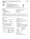
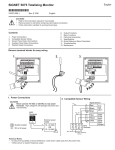
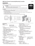
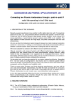
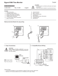
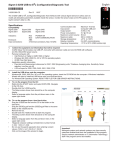
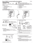
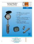
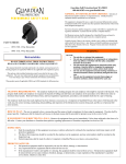
English
Signet 7000/7001 Vortex Flow Sensors
*3-7000.090*
3-7000.090
1.
2.
3.
4.
5.
6.
Rev. F 10/05
English
Mounting Location ...................................................... 1
Installation.................................................................... 1
Wiring Preparation ...................................................... 2
Wiring Options - Frequency Output Models ............. 3
Calibration - Frequency Output Models .................... 3
Wiring Options - Current Output Models .................. 4
7. Calibration - Current Output Models ......................... 5
8. Specifications .............................................................. 6
9. Spare Parts .................................................................. 8
10. Sensor Ordering Tree ............................................... 10
11. End Connectors Ordering Tree ............................... 10
12. Sensor Assembly Part Numbers ..............................11
1. Mounting Location
OPTION: Integral
Transmitter (local
readout)
Minimum upstream/downstream sensor mounting requirements:
•
The sensor must be mounted in a rigid pipe to minimize vibration. Always maximize distance
between the sensor and pump source.
•
Horizontal pipe runs: All mounting angles are acceptable. Avoid air bubbles.
•
Vertical pipe runs: All mounting angles are acceptable, with upward flow preferred.
•
A Reynold’s Number is a dimensionless number used to determine the
effects of viscosity, specific gravity, and velocity on flow
sensor performance. To maintain system accuracy, a
Sensor is shown without
its usual Cap and Adaptor
Reynold’s Number greater than 7,500 is required.
•
Reynold's number = 3162.76 x Q x Sg/(µ x ID)
where:
Q = Flow Rate in GPM;
Sg = Specific Gravity;
µ = Dynamic Viscosity in Centipoise;
ID = inside diameter in inches
•
Minimum downstream pipe backpressure levels
(full pipes) are required to prevent cavitation
within the sensor (section 8).
Vortices
w
lo
df
i
Inlet
"bluff body"
Outlet
Reducer
+GF+
25 x I.D.
5 x I.D.
5 x I.D.
2 x 90° Elbow
3 dimensions
+GF+
5 x I.D.
25 x I.D.
5 x I.D.
+GF+
XX DN XX X
XX
XX DN XX X
XX
25 x I.D.
5 x I.D.
20 x I.D.
5 x I.D.
.
2. Installation
Choose a mounting location that satisfies section 1 requirements.
Connector
+GF+
2.1 Fusion Socket or Solvent Cement Socket
•
Fusion socket version: available in HP PVDF, PVDF, or PP.
A George Fischer Socket Fusion Joining Machine is required to
install the end connectors on the pipeline. Refer to the joining
machine manual for installation details.
•
Solvent socket version: available in PVC. Follow the PVC cement manufacturer's recommendations and instructions. Avoid
excess cement in fitting joints to prevent port obstruction.
Sensor available in
PP, PVC, PVDF
XX DN XX X
XX
End
Pipe Union nut Connector O-Ring
•
15 x I.D.
2 x 90° Elbow
+GF+
XX DN XX X
XX
+GF+
XX DN XX X
XX
XX DN XX X
XX
10 x I.D.
•
90° Elbow
+GF+
XX DN XX X
XX
Valve/Gate
Order
Signet
3-8550-1,
3-8550-2, or
3-8550-3
Piezoelectric
sensor
Flu
Flange
S
Tranigs net Flow
mitte
r
Flow
O-Ring
Install sensor with arrow pointing in the direction of flow. These
flow sensors are not for bi-directional flow.
SAFETY INSTRUCTIONS
1. Do not remove from pressurized lines.
2. Never install sensor without O-Rings.
3. Confirm chemical compatibility before use.
4. Do not exceed maximum temperature/
pressure specifications.
5.
6.
7.
8.
Do not install/service without following mounting procedure.
Wear safety goggles and faceshield during installation/service.
Do not alter product construction.
Failure to follow safety instructions could result in severe
personal injury.
2.2 IR/Butt Fusion Sensors
•
Available in PVDF or PP. A George Fischer IR weld or Butt
Fusion Joining Machine is required to install the end connectors onto pipeline. Refer to the IR weld or butt fusion joining
machine manual for installation details.
IR/Butt Fusion
Connector Kit
+GF+
XX DN XX X
XX
Flow
End
Pipe
O-Ring
Union nut Connector
O-Ring
2.3 BCF/IR Sensors
•
A George Fischer SYGEF HP BCF/IR Fusion Joining Machine
is required to install the end connections. Refer to the SYGEF
BCF/IR fusion joining machine manual for installation details.
BCF/IR
+GF+
XX DN XX X
XX
SAFETY INSTRUCTIONS
1. Do not remove from pressurized lines.
2. Never install sensor without O-Rings.
3. Confirm chemical compatibility before use.
4. Do not exceed maximum temperature/pressure
specifications.
5. Do not install/service without following mounting procedure.
6. Wear safety goggles and faceshield during installation/service.
7. Do not alter product construction.
8. Failure to follow safety instructions could result in severe personal injury.
Pipe
Union
nut
End
Connector
Flow
O-Ring,
white
O-Ring,
white
NOTE:
Union Connectors are sold
separately (except for HP
- High Purity.)
3. Wiring Preparation
The vortex sensor's cap base is reversible for either upstream or downstream conduit port orientation. Optional: Refer to steps (A to
F) for conduit port reversal instructions. Required: Refer to steps (A to G) for external wiring requirements.
B
A
Conduit port
downstream
C
1. Locking
Ring
Turn Conduit Base 1/2
turn to the left and lift
D
Twist Conduit Base
1/2 turn to the right
2. Screw
Conduit
port
+GF+
XX DN XX X
XX
+GF+
+GF+
XX DN XX X
XX
XX DN XX X
XX
Flow
Mounting base
(top)
E
change
1. Insert locking ring
F
G
Threaded conduit (customer supplied) OR
2. Install screw
Conduit
upstream
14-22
AWG.
100-150 mm
4-6 in.
Watertight connector (customer supplied)
+FG+
X XX ND XX
XX
Loop cable
downward to prevent
moisture seepage
into housing
+GF+
XX DN XX X
XX
Flow
PG 13.5 or 1/2 in. NPT-conduit port
2
Signet 7000/7001 Vortex Flow Sensors
4. Wiring Options - Frequency Output Models
The open-collector frequency output requires a threewire connection between the sensor and the monitoring
device.
Ground
Loop -
To wire the vortex sensor frequency output to remote
equipment:
• Cable with single twisted-pair plus shield recommended.
• Maximum cable length 200 ft.
• Install cable through a conduit port and connect as
shown to the terminal block inside the vortex sensor
cap.
(for frequency out)
(for current output)
+
4-20 mA &
FREQ. OUT
WHITE
+3.5-24 VDC
+
BLACK
Out to
remote equipment
+DC Voltage
FREQ
OUT
ONLY
RED
FREQ OUT ONLY
Open Collector pulse (for frequency output)
Not used for current output systems
•
Open collector voltage is supplied by Signet instruments.
•
Use the 2535/2536 input card setting when wiring to the Signet 9010 Intelek-Pro Flow Controller
To wire the vortex sensor frequency output to a Signet 8550
Integral transmitter:
White
• Disconnect the sensor wires completely from the vortex sensor
cap. The cap will not be used.
Red
• Connect the Vortex sensor to the 8550 as shown.
Ground
Loop -
(frequency out)
(current output)
Open Collector pulse (for frequency output)
Not used for current output
Black
+3.5-24 VDC
+DC Voltage
9
Sensr Gnd
(SHIELD)
8
Sensr IN
(RED)
7
Sensr V+
(BLACK)
Signet 8550 Integral flow transmitter
+GF+
XX DN XX X
XX
5. Calibration - Frequency Output Models
This sensor model provides an open-collector frequency output directly proportional to the flow rate. The frequency output is held at
0 Hz. When the flow rate is below the minimum operating range (see specs.). The following K-factors represent the number of pulses
generated by the sensor for each engineering unit of water measured. If fluids other than water are used, then custom calibration is
required.
K-Factors - ANSI & Metric Piping Systems
Sensor
Material
Flow
Units
d20 DN15 (-x1)
d25 DN20 (-x2)
d32 DN25 (-x3)
d40 DN32 (-x4)
d50 DN40 (-x5)
d63 DN50 (-x6)
(i.d.≈0.5 inch)
(i.d.≈0.75 inch)
(i.d.≈1 inch)
(i.d.≈1.25 inch)
(i.d≈1.5 inch)
(i.d≈2 inch)
PVC, SCH 80
3-7000-5x
U.S. Gallons
1837.39
802.34
361.30
138.76
88.296
39.133
Liters
485.44
211.98
95.455
36.660
23.328
10.339
PVC, Metric
3-7000-6x
U.S. Gallons
1248.31
538.45
243.84
114.66
61.415
29.686
Liters
329.81
140.50
64.422
30.292
16.226
7.843
PP, Metric
3-7000-4x
U.S. Gallons
1385.46
572.51
265.76
138.41
70.719
35.096
Liters
366.04
151.26
70.213
36.568
18.684
9.272
PVDF, Metric
3-7000-3x
U.S. Gallons
1381.71
582.63
265.97
111.81
50.732
25.443
Liters
365.05
153.93
70.270
29.540
13.403
6.722
HP PVDF
BCF/IR Socket (-2x)
U.S. Gallons
1396.90
575.71
254.11
110.86
50.431
25.537
Liters
369.07
152.10
67.137
29.288
13.324
6.747
HP PVDF
BCF/IR Butt (-1x)
U.S. Gallons
1400.00
575.70
254.31
110.48
51.855
25.568
Liters
369.88
152.10
67.190
29.188
13.700
6.755
K-factor Conversion Formulas:
1 U.S. gallon = 0.003785 cubic meters
1 U.S. gallon = 3.785 liters
1 U.S. gallon = 0.0000003069 acre feet
1 U.S. gallon = 0.8327 imperial gallons
1 U.S. gallon = 8.3454 pounds of water
Signet 7000/7001 Vortex Flow Sensors
3
6. Wiring Options - Current Output Models
4-20 mA &
FREQ. OUT
+
WHITE
FREQ
OUT
ONLY
BLACK
4 to 20 mA
PLC
RED
•
PLC without an internal transmitter power supply
CH +
+
Fuse**
1/8A
+GF+
+
WHITE
FREQ
OUT
ONLY
BLACK
4 to 20 mA
indicator
RED
•
PLC with a 4 to 20 mA indicator
CH +
+
Fuse**
1/8A
+GF+
4-20 mA &
FREQ. OUT
External
power
supply
24*
VDC
+
XX DN XX X
XX
CH (gnd)
-
+
WHITE
FREQ
OUT
ONLY
BLACK
1 to 5 VDC
recorder
RED
PLC with a 1 to 5 VDC chart
recorder
+GF+
XX DN XX X
XX
*
CH +
+
+
Fuse**
1/8A
External
power
supply
24*
VDC
250Ω*
•
250Ω*
-
+
XX DN XX X
XX
4-20 mA &
FREQ. OUT
External
power
supply CH (gnd)
24*
VDC
-
CH (gnd)
Refer to the maximum Loop Impedance for minimum operating voltage requirements in the Specifications section.
** 1/8 Amp. fuse recommended (customer supplied)
4
Signet 7000/7001 Vortex Flow Sensors
7. Calibration - Current Output Models
This sensor model outputs a 4 to 20 mA current signal directly proportional to the flow rate. The current output is held at 4 mA when
flow is less than the minimum velocity specification, and increases to 20 mA at the maximum flow velocity specification, see section 8.
Use the following formula to calculate the expected current output level at a specific flow velocity.
Fluid Velocity in pipe
X 16 + 4 = Expected current
Max sensor velocity (section 8)
output (mA)
Scale the receiving devices such that 4 mA = zero flow and 20 mA
= full scale (max flow)
Loop Range: GPM
00.000 -> 100.00
Example: In a pipe with a flow velocity of 2 m/s, the expected current output is calculated as 12.0 mA.
Jumps above 4 mA
up to minimum flow
reading
2 (m/s)
X 16
4 (m/s)
+ 4
= 12.0 mA
< min flow
= 4mA
20 mA
Maximum
Flow Rate
(saturates
at 20 mA)
Minimum
Flow Rate
(clamped at 4mA
until min. flow rate)
max. flow
(100 gpm in
this example)
0
Flow Rate
V = flowrate
v = known flow
velocity
4 mA
OPERATIONAL SCENARIO: At low flow (below minimum flow
rate for this sensor), sensor output is 4 mA. The instant the flow
rate exceeds the minimum, the output jumps to reflect the min.
measurable flow rate. At max. flow rate, output peaks at 20 mA.
7.1 Velocity to Rate or Rate to Velocity Conversion Formulas
A. Metric Conversion Formulas
Current Output
in milliAmps (mA)
V (lpm) to v (m/s)
v = V / (id2 * 0.0471)
Optional:
v (m/s) to V (lpm)
V = v * id2 * 0.0471
EXAMPLES:
lpm to m/s:
PVDF, sensor d63 with a known flowrate V = 200 lpm (id = 55 from table below);
v(m/s) = 200 / (552 * 0.0471) = 1.40
m/s to lpm:
(optional)
PVC sensor, d32 with a known flow velocity v = 2 m/s (id = 26 from table below);
V(lpm) = 2 * 262 * 0.0471= 63.68
B. American Conversion Formulas
V = flowrate
v = known flow velocity
V (gpm) to v (ft/s)
v = V / (id2 * 0.0038)
Optional:
v (ft/s) to V (gpm)
V = v * id2 * 0.0038
EXAMPLES:
gpm to ft/s:
PVDF, sensor d63 with a known flowrate V = 100 gpm (id = 55 from table below);
ft/s to gpm:
(optional)
v(ft/s) = 100 / (552 * 0.0038) = 8.7
PVC sensor, d32 with a known flow velocity v = 10 ft/s (id = 26 from table below);
V(gpm) = 10 * 262 * 0.0038 = 25.69
1 lpm = 0.264 gpm
1 m/s = 3.28 ft/s
Metric Conversion Data
Sensors
PVDF / HP
PVDF
PP
PVC Schedule 80
PVC Metric
Pipe Size
Min Flow
American Conversion Data
Max Flow
Min Flow
Max Flow
v (m/s)
V (lpm)
v (m/s)
V (lpm)
v (ft/s)
V (gpm)
v (ft/s)
V (gpm)
d20 DN15
0.50
4.98
4.00
39.66
1.64
1.32
13.12
10.48
d25 DN20
0.50
8.94
4.00
71.70
1.64
2.36
13.12
18.94
d32 DN25
0.40
11.76
4.00
117.78
1.31
3.11
13.12
31.12
d40 DN32
0.40
21.18
4.00
211.56
1.31
5.60
13.12
55.89
d50 DN40
0.30
26.76
4.00
356.70
0.98
7.07
13.12
94.24
d63 DN50
0.30
42.78
4.00
570.18
0.98
11.30
13.12
150.64
d20 DN15
0.50
4.98
4.00
39.66
1.64
1.32
13.12
10.48
d25 DN20
0.50
8.94
4.00
71.70
1.64
2.36
13.12
18.94
d32 DN25
0.40
11.76
4.00
117.78
1.31
3.11
13.12
31.12
d40 DN32
0.40
18.12
4.00
181.14
1.31
4.79
13.12
47.86
d50 DN40
0.30
21.48
4.00
286.68
0.98
5.68
13.12
75.74
d63 DN50
0.30
34.62
4.00
461.88
0.98
9.15
13.12
122.03
1/2 in.
0.50
4.29
4.00
31.86
1.64
1.13
13.12
8.42
3/4 in.
0.50
7.63
4.00
57.73
1.64
2.02
13.12
15.25
1 in.
0.40
9.97
4.00
95.43
1.31
2.63
13.12
25.21
1 1/4 in.
0.40
18.70
4.00
181.14
1.31
4.94
13.12
47.86
1 1/2 in.
0.30
19.35
4.00
251.12
0.98
5.11
13.12
66.35
2 in.
0.30
32.57
4.00
425.29
0.98
8.61
13.12
112.36
d20 DN15
0.50
5.28
4.00
42.42
1.64
1.39
13.12
11.21
d25 DN20
0.50
9.42
4.00
75.42
1.64
2.49
13.12
19.93
d32 DN25
0.40
12.72
4.00
127.44
1.31
3.36
13.12
33.67
d40 DN32
0.40
20.52
4.00
205.26
1.31
5.42
13.12
54.23
d50 DN40
0.30
23.76
4.00
316.86
0.98
6.28
13.12
83.71
d63 DN50
0.30
38.22
4.00
509.70
0.98
10.10
13.12
134.66
Signet 7000/7001 Vortex Flow Sensors
5
8. Specifications
Pressure Drop Graph
•
psi
Minimum downstream pipe backpressure levels (full
pipes) are required to prevent cavitation within the
sensor. The minimum backpressure is calculated
by the following formula: 2.7 x ∆P + 1.3 x Po (∆P =
Pressure drop across sensor. Po = Water saturation
vapor pressure at operating temperature.)
3. Calculate minimum back pressure needed using
formula.
conduit base
(enclosure box)
0.10
1.45
1. Using Pressure Drop Graph, find ∆P by locating your
maximum flow rate on specific sensor size line.
2. Using the Water Saturation Vapor Pressures Chart,
find Po at operating temperature.
bar
1.00
14.5
Sensor size:
1
3.78
10
37.8
bar
16
14
10
Pressure
Technical Data
Wetted materials:
FPM or EPDM
psi
PVDF-PN16
203
PVC-PN16
174
PP-PN10
145
9 130.5
8
116
7 101.5
6
87
5
72.5
4
58
3
43.5
2
29
1
14.5
0
0
-58 -40 -22
-4 14
32
-50 -40 -30 -20 -10 0
Pipe size range:
•
PP/PVDF, Metric:
d20 to 63 mm, DN15 to 50 mm
•
PVC, SCH 80:
0.5 to 2.0 in.
50
68
86
104 122 140 158
10- 20
30
40
50
60
Current loop (2-wire):
Loop impedance:
1 Ω maximum at 7 VDC
•
d20 to d25 (0.5 to 0.75 in.) sensors: 0.5 to 4 m/s (1.6 to 13 ft/s)
300 Ω maximum at 12 VDC
•
d32 to d40 (1.0 to 1.25 in.) sensors: 0.4 to 4 m/s (1.3 to 13 ft/s)
800 Ω maximum at 24 VDC
•
d50 to d63 (1.5 to 2.0 in.) sensors:
1000 Ω maximum at 30 VDC
0.3 to 4 m/s (1.0 to 13 ft/s)
NOTE: Below these velocity ranges, Vortex output is non-linear.
•
4 to 20 mA output fixed from 0 to 13 ft/s
Enclosure:
•
Resolution:
•
Rating:
NEMA 4X/IP65
Environmental
•
Material:
PC/PBT blend of resins
Maximum media press./temp.:
•
Seals (2):
Buna-N
•
PVDF:
•
Accuracy:
±1% of reading @ 25°C
•
Repeatability:
±0.5% of reading @ 25°C
•
Immunity:
EN50082-2
•
Emissions:
EN55011
Reverse polarity protection
Electrical - Frequency Output Model
•
Power:
3.5 to 24 VDC, regulated, 1.5 mA max
•
Output type:
Open-collector NPN transistor,
10 mA max sink,
24 VDC max pull-up voltage, 0 to 300 Hz (size
dependent), 50% duty cycle, non-isolated
Electrical - Current Output Model
•
6
Power:
6 µA
16 bar @ 0°C, 9.8 bar @ 65°C
(232 psi @ 32°F, 144 psi @ 149°F)
Electrical:
•
70
Temperature
•
Flow range:
1000
37855
232
15 217.5
Kit,Adapter, NPT to PG 13.5
3-0000.393
159.000.618
PVC, PP, PVDF, or SYGEF HP PVDF
100
378
°C
-20
-10
0
10
20
25
30
40
50
65
°F
-4
14
32
50
68
77
86
104 122 149
Po (bar) 0.001 0.003 0.006 0.012 0.023 0.32 0.042 0.074 0.123 0.25
Po (psia) 0.014 0.038 0.088 0.178 0.338 0.458 0.614 1.067 1.784 3.626
PG 13.5
Center Adapter Liquid
NPT
to
line
tight
PG 13.5
Conn.
Union O-Rings:
d63
Water Saturation Vapor Pressures at Operation Temperatures
11 159.5
Sensor:
d50
d40
0.01
gpm
lpm
12
•
d32
Medium: Water
@ 20 °C (68 °F)
13 188.5
•
d25
Flow Rate (V)
0.145
3 3/4"
Ring
Seal
Dimensions of
Adapter & Liquid
Tight Connector
as Mounted
d20
Pressure Drop (∆P)
Backpressure Calculation
10 to 27 VDC, regulated, 20 mA max
•
PP:
10 bar @ 0°C, 2.9 bar @ 65°C
•
PVC:
•
Ambient temp.: 0 to 65°C (32 to 149°F)
•
Storage temp.: -15 to 80°C (5 to 176°F)
•
Relative humidity:
•
Max. vibration: 1 mm or 1g double amplitude @ 500 Hz
(145 psi @ 32°F, 42 psi @ 149°F)
16.2 bar @ 0°C, 3.7 bar @ 60°C
(235 psi @ 32°F, 54 psi @ 140°F)
0 to 95%, non-condensing
Standards and Approvals
•
Manufactured under ISO 9001 and ISO 14001
•
CE
Signet 7000/7001 Vortex Flow Sensors
Dimensions
HP BC F/ IR True Union
HP BCF/IR True Union
Conduit port:
PG13.5 or
1/2 in. NPT
H
+GF+
XX DN XX X
XX
d
D
d
Closest DN
D
L
l
mm inch size mm mm inch mm inch mm inch
20
1/2
15
47 1.85 226 8.90 90 3.54
25
3/4
20
57 2.24 236 9.29 100 3.94
32
1
25
64 2.52 248 9.76 110 4.33
40 1-1/4
32
78 3.07 286 11.26 110 4.33
50 1-1/2
40
89 3.50 298 11.73 120 4.72
63
2
50 109 4.29 317 12.48 130 5.12
H
e
mm inch mm
117 4.61 1.9
120 4.72 1.9
123 4.84 2.4
127 5.00 2.4
132 5.20 3.0
139 5.47 3.0
l
e
L
•
HP BCF/IR True Union supplied with white FPM o-rings.
•
All HP Sensors are 100% cleaned, inspected and double-bagged in
heat-sealed PA6/PE liners.
HP Socket Fusion True Union
PVDF Socket Fusion
PP Socket Fusion
HP Socket Fusion True Union; PVDF and PP, Socket Fusion
d
C losest DN
D
L
l
H
mm Inch size mm mm inch mm inch mm inch mm inch
20
1/2
15 47 1.85 128 5.04 90 3.54 117 4.61
25
3/4
20 57 2.24 142 5.59 100 3.94 120 4.72
32
1
25 64 2.52 156 6.14 110 4.33 123 4.84
40 1-1/4 32 78 3.07 160 6.30 110 4.33 127 5.00
50 1-1/2 40 89 3.50 176 6.93 120 4.72 132 5.20
63
2
50 109 4.29 194 7.64 130 5.12 139 5.47
Conduit port:
PG13.5 or
1/2 in. NPT
H
+GF+
XX DN XX X
XX
d D
l
•
HP Socket Fusion True Union supplied with black FPM o-rings.
L
•
All HP Sensors are 100% cleaned, inspected and double-bagged in
heat-sealed PA6/PE liners.
Dimension L ± 3 mm (±0.1 in.)
PVDF Butt Fusion / IR
PP Butt Fusion / IR
Conduit port:
PG13.5 or
1/2 in. NPT
H
+GF+
XX DN XX X
XX
D
e
l
PVDF & PP Butt Fusion/IR connectors
d
C losest DN
D
L
l
H
e
mm Inch size mm mm inch mm inch mm inch mm inch mm
20
1/2
15 47 1.85 196 7.72 90 3.54 117 4.61 1.9
25
3/4
20 57 2.24 212 8.35 100 3.94 120 4.72 1.9
32
1
25 64 2.52 228 8.98 110 4.33 123 4.84 2.4
40 1-1/4 32 78 3.07 234 9.21 110 4.33 127 5.00 2.4
50 1-1/2 40 89 3.50 250 9.84 120 4.72 132 5.20 3.0
63
2
50 109 4.29 266 10.47 130 5.12 139 5.47 3.0
L
Dimension L ± 3 mm (±0.1 in.)
Shown with Butt Fusion/IR connectors
PVC Sch 80 Solvent Socket;
PVC Metric Solvent Socket
Conduit port:
PG13.5 or
1/2 in. NPT
PVC Sch 80 Solvent Socket
D
L
Inch size mm inch mm inch
1/2
43 1.69 128 5.04
3/4
53 2.09 144 5.67
1
60 2.36 160 6.30
1-1/4
74 2.91 168 6.61
1-1/2
83 3.27 188 7.40
2
103 4.06 212 8.35
l
mm
90
100
110
110
120
130
inch
3.54
3.94
4.33
4.33
4.72
5.12
H
mm inch
117 4.61
120 4.72
123 4.84
127 5.00
132 5.20
139 5.47
H
+GF+
XX DN XX X
XX
d D
l
L
Dimension L ± 3 mm (±0.1 in.)
Signet 7000/7001 Vortex Flow Sensors
PVC Metric Solvent Socket
d
C losest DN
D
mm Inch size mm mm inch
20
1/2
15 43 1.69
25
3/4
20 53 2.09
32
1
25 60 2.36
40 1-1/4
32 74 2.91
50 1-1/2
40 83 3.27
63
2
50 103 4.06
mm
136
150
166
166
186
196
L
inch
5.35
5.91
6.54
6.54
7.32
7.72
l
mm
90
100
110
110
120
130
inch
3.54
3.94
4.33
4.33
4.72
5.12
H
mm inch
117 4.61
120 4.72
123 4.84
127 5.00
132 5.20
139 5.47
7
9. Spare Parts
For retrofit of earlier Signet
part numbers 152.xxx.xxx,
use 3-8055.
screw
PG 13.5 Liquid tight Conn.
locking ring
Conduit Base Kit
3-8054
159.000.619
threaded
plug
Adapter NPT to PG 13.5
conduit base
(enclosure box)
Ring Nut
3-8050.562-2
159.000.621
Kit,Adapter, NPT to PG 13.5
3-0000.393
159.000.618
Ring Seal
base seal
+GF+
XX DN XX X
XX
End
Union conn.
nut
O-Ring (see table below)
End Connector Kit (see table on next page)
NOTE:
For Sensor part numbers, see pages 10
and 11
Spare O-Rings
8
Description
“Size
(mm)”
Material
“Mfr. Part No.
(2 pieces)”
“Code
(1 piece. order 2 pcs.)”
O-Ring(s) [1 or 2 pieces]
d20
EPDM
3-7000.390-01
748.410.038
O-Ring(s) [1 or 2 pieces]
d25
EPDM
3-7000.390-02
748.410.044
O-Ring(s) [1 or 2 pieces]
d32
EPDM
3-7000.390-03
748.410.195
O-Ring(s) [1 or 2 pieces]
d40
EPDM
3-7000.390-04
748.410.052
O-Ring(s) [1 or 2 pieces]
d50
EPDM
3-7000.390-05
748.410.134
O-Ring(s) [1 or 2 pieces]
d63
EPDM
3-7000.390-06
748.410.135
O-Ring(s) [1 or 2 pieces]
d20
FPM (Viton)
3-7000.390-07
749.410.038
O-Ring(s) [1 or 2 pieces]
d25
FPM (Viton)
3-7000.390-08
749.410.044
O-Ring(s) [1 or 2 pieces]
d32
FPM (Viton)
3-7000.390-09
749.410.195
O-Ring(s) [1 or 2 pieces]
d40
FPM (Viton)
3-7000.390-10
749.410.052
O-Ring(s) [1 or 2 pieces]
d50
FPM (Viton)
3-7000.390-11
749.410.134
O-Ring(s) [1 or 2 pieces]
d63
FPM (Viton)
3-7000.390-12
749.410.135
O-Ring(s) [1 or 2 pieces]
d20
FPM white
3-7000.390-13
749.410.005
O-Ring(s) [1 or 2 pieces]
d25
FPM white
3-7000.390-14
749.410.006
O-Ring(s) [1 or 2 pieces]
d32
FPM white
3-7000.390-15
749.410.120
O-Ring(s) [1 or 2 pieces]
d40
FPM white
3-7000.390-16
749.410.062
O-Ring(s) [1 or 2 pieces]
d50
FPM white
3-7000.390-17
749.410.172
O-Ring(s) [1 or 2 pieces]
d63
FPM white
3-7000.390-18
749.410.054
Signet 7000/7001 Vortex Flow Sensors
9. Spare Parts (continued)
Spare End Connectors
Mfr. Part No.
Code
Size
END CONNECTOR Material
Complete Kit:
2 ring nuts
2 end connectors
End Connector
Single piece
Union Nut
Single piece
d20
PVDF, Metric, Butt Fusion, 1/2”
3-7000.391-11
735.608.606
735.690.406
d25
PVDF, Metric, Butt Fusion, 3/4”
3-7000.391-12
735.608.607
735.690.407
d32
PVDF, Metric, Butt Fusion, 1”
3-7000.391-13
735.608.608
735.690.408
d40
PVDF, Metric, Butt Fusion, 1 1/4”
3-7000.391-14
735.608.609
735.690.409
d50
PVDF, Metric, Butt Fusion, 1 1/2”
3-7000.391-15
735.608.610
735.690.410
d63
PVDF, Metric, Butt Fusion, 2”
3-7000.391-16
735.608.611
735.690.411
d20
PVDF, Metric, Fusion Socket, 1/2”
3-7000.391-21
735.600.106
735.690.406
d25
PVDF, Metric, Fusion Socket, 3/4”
3-7000.391-22
735.600.107
735.690.407
d32
PVDF, Metric, Fusion Socket, 1”
3-7000.391-23
735.600.108
735.690.408
d40
PVDF, Metric, Fusion Socket, 1 1/4”
3-7000.391-24
735.600.109
735.690.409
d50
PVDF, Metric, Fusion Socket, 1 1/2”
3-7000.391-25
735.600.110
735.690.410
d63
PVDF, Metric, Fusion Socket, 2”
3-7000.391-26
735.600.111
735.690.411
d20
PP Metric, Butt Fusion, 1/2”:
3-7000.391-31
727.608.506
727.690.406
d25
PP Metric, Butt Fusion, 3/4”
3-7000.391-32
727.608.507
727.690.407
d32
PP Metric, Butt Fusion, 1”
3-7000.391-33
727.608.508
727.690.408
d40
PP Metric, Butt Fusion, 1 1/4”
3-7000.391-34
727.608.509
727.690.409
d50
PP Metric, Butt Fusion, 1 1/2”
3-7000.391-35
727.608.510
727.690.410
d63
PP Metric, Butt Fusion, 2”
3-7000.391-36
727.608.511
727.690.411
d20
PP Metric, Fusion Socket, 1/2”
3-7000.391-41
727.600.106
727.690.406
d25
PP Metric, Fusion Socket, 3/4”
3-7000.391-42
727.600.107
727.690.407
d32
PP Metric, Fusion Socket, 1”
3-7000.391-43
727.600.108
727.690.408
d40
PP Metric, Fusion Socket, 1/1/4”
3-7000.391-44
727.600.109
727.690.409
d50
PP Metric, Fusion Socket, 1 1/2”
3-7000.391-45
727.600.110
727.690.410
d63
PP Metric, Fusion Socket, 2”
3-7000.391-46
727.600.111
727.690.411
d20
PVC Sch80, 1/2”
3-7000.391-51
721.602.006
721.690.006
d25
PVC Sch80, 3/4”
3-7000.391-52
721.602.007
721.690.007
d32
PVC Sch80, 1”
3-7000.391-53
721.602.008
721.690.008
d40
PVC Sch80, 1 1/4”
3-7000.391-54
721.602.009
721.690.009
d50
PVC Sch80, 1/1/2”
3-7000.391-55
721.602.010
721.690.010
d63
PVC Sch80, 2”
3-7000.391-56
721.602.011
721.690.011
d20
PVC Metric, 1/2”
3-7000.391-61
721.600.106
721.690.006
d25
PVC Metric, 3/4”
3-7000.391-62
721.600.107
721.690.007
d32
PVC Metric, 1”
3-7000.391-63
721.600.108
721.690.008
d40
PVC Metric, 1 1/4”
3-7000.391-64
721.600.109
721.690.009
d50
PVC Metric, 1 1/2”
3-7000.391-65
721.600.110
721.690.010
d63
PVC Metric, 2”
3-7000.391-66
721.600.111
721.690.011
Signet 7000/7001 Vortex Flow Sensors
9
10. Sensor Ordering Tree
•
To select a replacement sensor:
a) determine if your sensor has a pulse (frequency) or
current output;
b) determine material type and configuration;
c) determine size.
+GF+
+GF+
XX DN XX X
XX
XX DN XX X
XX
High Purity (HP)
Industrial
OUTPUT
0
Frequency Output
1
Current Output (4 to 20 mA)
3 - 70 0 o - m s
SIZE
MAT'L./CONFIG.
*SYGEF HP-PVDF BCF/IR
d
DN
Å inches
Butt Fusion True Union
(end connectors included)
*SYGEF HP-PVDF BCF/IR
Socket Fusion True Union
(end connectors included)
1
20mm 15mm 1/2
2
25mm 20mm 3/4
3
PVDF
3
32mm 25mm 1
4
PP
4
40mm 32mm 1 1/4
5
PVC Sch 80
Solvent Socket
5
50mm 40mm 1 1/2
6
PVC Metric
Solvent Socket
6
63mm 50mm 2
1
2
End connector kit options for these sensors
are ordered separately. Use selection tree
below to determine part number
*SYGEF¨ HP is the George Fischer
High Purity PVDF formulation and process.
11. End Connectors Ordering Tree
3 - 7000. 391 - m s
MAT'L./CONFIG.
10
SIZE
1
PVDF Metric, Butt Fusion
1
d20
1/2"
2
PVDF Metric, Fusion Socket
2
d25
3/4"
3
PP Metric, Butt Fusion
3
d32
1"
4
PP Metric, Fusion Socket
4
d40
1 1/4"
5
PVC Sch 80
5
d50
1 1/2"
6
PVC Metric
6
d63
2"
Signet 7000/7001 Vortex Flow Sensors
12. Sensor Assembly Part Numbers
Electrical
Frequency
3-7000
Materials/Configuration
HP Union BCF/IR True Union
(High Purity Polyvinylidene Fluoride
Bead and Crevice Free /
/ Infra-Red welded)
(shipped with white FPM O-rings)
HP PVDF Socket Fusion True Union
(shipped with FPM O-rings)
PVDF
(shipped with FPM O-rings)
Polypropylene
(shipped with FPM O-rings)
PVC Sch 80 Solvent Socket
(shipped with EPDM O-rings)
PVC Metric Solvent Socket
(shipped with EPDM O-rings)
Signet 7000/7001 Vortex Flow Sensors
Size (mm) ≈Size (in.)
Mfr. Part No.
Code
d20
0.50
3-7000-11
159 000 106
d25
0.75
3-7000-12
159 000 107
d32
1.00
3-7000-13
159 000 108
d40
1.25
3-7000-14
159 000 109
d50
1.50
3-7000-15
159 000 110
d63
2.00
3-7000-16
159 000 111
d20
0.50
3-7000-21
159 000 112
d25
0.75
3-7000-22
159 000 113
d32
1.00
3-7000-23
159 000 114
d40
1.25
3-7000-24
159 000 115
d50
1.50
3-7000-25
159 000 116
d63
2.00
3-7000-26
159 000 117
d20
0.50
3-7000-31
159 000 118
d25
0.75
3-7000-32
159 000 119
d32
1.00
3-7000-33
159 000 120
d40
1.25
3-7000-34
159 000 121
d50
1.50
3-7000-35
159 000 123
d63
2.00
3-7000-36
159 000 123
d20
0.50
3-7000-41
159 000 124
d25
0.75
3-7000-42
159 000 125
d32
1.00
3-7000-43
159 000 126
d40
1.25
3-7000-44
159 000 127
d50
1.50
3-7000-45
159 000 128
d63
2.00
3-7000-46
159 000 1299
d20
0.50
3-7000-51
159 000 130
d25
0.75
3-7000-52
159 000 131
d32
1.00
3-7000-53
159 000 132
d40
1.25
3-7000-54
159 000 133
d50
1.50
3-7000-55
159 000 134
d63
2.00
3-7000-56
159 000 135
d20
0.50
3-7000-61
159 000 136
d25
0.75
3-7000-62
159 000 137
d32
1.00
3-7000-63
159 000 138
d40
1.25
3-7000-64
159 000 139
d50
1.50
3-7000-65
159 000 140
d63
2.00
3-7000-66
159 000 141
11
12. Sensor Part Numbers (continued)
Electrical
Materials/Configuration
Size (mm)
≈Size (in.)
Mfr. Part No.
Code
Current
3-7001
HP Union BCF/IR True Union
(High Purity Polyvinylidene Fluoride
Bead and Crevice Free /
/ Infra-Red welded)
(shipped with white FPM O-rings)
HP PVDF Socket Fusion True Union
d20
0.50
3-7001-11
159.000.148
d25
0.75
3-7001-12
159.000.149
d32
1.00
3-7001-13
159.000.150
d40
1.25
3-7001-14
159.000.151
d50
1.50
3-7001-15
159.000.152
d63
2.00
3-7001-16
159.000.153
d20
0.50
3-7001-21
159.000.154
d25
0.75
3-7001-22
159.000.155
d32
1.00
3-7001-23
159.000.156
d40
1.25
3-7001-24
159.000.157
d50
1.50
3-7001-25
159.000.158
d63
2.00
3-7001-26
159.000.159
d20
0.50
3-7001-31
159.000.160
d25
0.75
3-7001-32
159.000.161
d32
1.00
3-7001-33
159.000.162
d40
1.25
3-7001-34
159.000.163
d50
1.50
3-7001-35
159.000.164
d63
2.00
3-7001-36
159.000.165
d20
0.50
3-7001-41
159.000.166
d25
0.75
3-7001-42
159.000.167
d32
1.00
3-7001-43
159.000.168
d40
1.25
3-7001-44
159.000.169
d50
1.50
3-7001-45
159.000.170
(shipped with FPM O-rings)
PVDF
(shipped with FPM O-rings)
Polypropylene
(shipped with FPM O-rings)
d63
2.00
3-7001-46
159.000.171
PVC Sch 80 Solvent Socket
d20
0.50
3-7001-51
159.000.172
d25
0.75
3-7001-52
159.000.173
d32
1.00
3-7001-53
159.000.174
d40
1.25
3-7001-54
159.000.175
d50
1.50
3-7001-55
159.000.176
d63
2.00
3-7001-56
159.000.177
d20
0.50
3-7001-61
159.000.178
d25
0.75
3-7001-62
159.000.179
d32
1.00
3-7001-63
159.000.180
d40
1.25
3-7001-64
159.000.181
d50
1.50
3-7001-65
159.000.182
d63
2.00
3-7001-66
159.000.183
(shipped with EPDM O-rings)
PVC Metric Solvent Socket
(shipped with EPDM O-rings)
George Fischer Signet, Inc. 3401 Aerojet Avenue, El Monte, CA 91731-2882 U.S.A. • Tel. (626) 571-2770 • Fax (626) 573-2057
For Worldwide Sales and Service, visit our website: www.gfsignet.com • Or call (in the U.S.): (800) 854-4090
3-7000.090 Rev.F 10/05 English
© George Fischer Signet, Inc. 2002
Printed in U.S.A. on recyclable paper