1
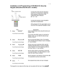
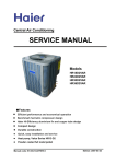
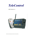
+
INSTALLATION MANUAL
1.0
HOME ENERGY SAVINGS
REMOTE CAMERA
INTERNET USER INTERFACE
TEMPERATURE ALARMS
BURGLARY PROTECTION
DOOR SECURITY
FIRE SAFETY
SECURITY KEYPAD WITH PROXIMITY TAGS
PREVENTION OF WATER DAMAGES
WIRELESS EXTENSIONS
Installation Certificate
This certificate states that Telemic Oy’s HouseControl remote control and alarm system has been
installed in the real estate mentioned below.
Property holder / holder of real estate
Location of the real estate
Real estate
Alarm system type
Central unit’s serial number
SIM card phone number
Smoke detector model
Motion sensor model
Magnetic door switches
Remote camera
Security keypad
Siren
Installed by
We assure
-
that the alarm system was installed in accordance with the manufacturer’s instructions.
-
that the alarm system has been tested and it works as documented.
-
that the end user has received guidance as to how to use the alarm system.
Location and date
Installed by / Signature
This form needs to be filled and signed in order to apply for possible refund from your insurance company and
before contacting product support.
1
1.
INTRODUCTION....................................................................................................................... 2
2.
PREPARATION........................................................................................................................ 2
2.1
REQUIRED TOOLS............................................................................................................... 2
2.2
PACKAGE CONTENTS .......................................................................................................... 3
2.3
ACCESSORIES .................................................................................................................... 3
3.
INSTALLATION........................................................................................................................ 4
3.1
OPENING UNIT’S COVER ..................................................................................................... 4
3.2
HCE+ FROM INSIDE ............................................................................................................ 4
3.3
CONNECTORS .................................................................................................................... 4
3.4
CENTRAL UNIT ................................................................................................................... 5
3.5
REMOTE CAMERA ............................................................................................................... 6
3.6
INDOOR TEMPERATURE SENSOR .......................................................................................... 6
3.7
OUTDOOR TEMPERATURE SENSOR ...................................................................................... 6
3.8
W ATER TEMPERATURE SENSOR .......................................................................................... 7
3.9
SIREN ............................................................................................................................... 7
3.10
MAGNETIC DOOR SWITCHES................................................................................................ 7
3.11
MOISTURE SENSOR ............................................................................................................ 8
3.12
MOTION SENSOR................................................................................................................ 8
3.13
SMOKE DETECTOR ............................................................................................................. 9
3.14
SECURITY KEYPAD ........................................................................................................... 10
3.15
HEATER RELAY ................................................................................................................ 11
3.16
EXT RELAY ..................................................................................................................... 11
3.17
POWER SUPPLY AND BATTERY BACKUP UNIT ...................................................................... 12
3.18
SIM CARD ....................................................................................................................... 12
3.19
W IRELESS EXTENSION ...................................................................................................... 13
4.
SETUP AND TESTING ........................................................................................................... 13
4.1
TESTING .......................................................................................................................... 13
2
1.
HouseControl E+ Installation Manual
INTRODUCTION
This manual describes the installation of HouseControl remote control and alarm system. The
instructions in this manual can be applied to many kinds of houses.
It is important that you plan carefully how you are going to install HouseControl. For example, to achieve
finished look make sure the cables run inside the walls and other structures. This requires that you have
a plan for where you are going to install smoke detectors, motion sensors, and other accessories as you
are building your house.
You can connect up to three temperature sensors, a siren, a magnetic door switch, a moisture sensor, a
smoke detector, a motion sensor, a security keypad, a remote camera and a control panel to the central
unit. You can connect several motion sensors, magnetic door switches, smoke detectors and moisture
sensors to one input. Always connect the sensors according to the separate wiring diagram.
The central unit contains two relay outputs 230VAC/AC (6A and 10A). The 10A relay can be controlled
thermostatically.
2.
PREPARATION
You need a GSM subscription and a SIM card from a telecommunications operator for testing and using
HouseControl. You must disable the PIN code request from the SIM card before inserting the card in the
central unit. It is recommended that testing is conducted with the same SIM card that will remain in the
central unit after the installation is complete.
If a camera is installed, you should make sure that MMS messages (messages that contain pictures)
can be sent from the subscription. Some operators require that the service is activated before it can be
used. You can activate MMS by inserting the SIM card in an MMS compatible phone and sending an
activation message to your operator. Please consult your telecommunications operator for more
information. Before inserting the SIM card in HouseControl make sure that you indeed can send MMS
messages with that SIM card by testing it with your mobile phone.
Use an unlisted phone number in your HouseControl so that it is not publicly available. However,
make sure that the HouseControl’s phone number is displayed on the screen of your mobile
phone when it calls you (i.e. HouseControl’s phone number is sent with the call and is not
hidden).
2.1 Required Tools
You will need the following tools:
•
Side cutters for cables
•
Pointed pliers to help you connect wires to connectors
•
Electrical drill and drill bits of various sizes
•
Screwdriver
PREPARATION
3
2.2 Package Contents
Central unit package
Battery backup unit package
Temperature sensors
Battery
Check the package contents:
Central unit
Moisture sensor
Magnetic door switch (flush mounting)
2 temperature sensors
Siren
Motion sensor
Smoke detector
Battery backup unit
And:
-
Materials needed in installation
Installation cable
User’s Manual and Installation Manual
2.3 Accessories
The following accessories are available to HouseControl:
Magnetic door switch (flush and surface mounting)
Security keypad with proximity tags
Remote camera
Moisture sensor
Siren with light
Temperature sensor
Heat detector
Carbon monoxide detector
HCE Wireless extension: detectors and remote controls
4
3.
HouseControl E+ Installation Manual
INSTALLATION
3.1 Opening Unit’s Cover
There is a small curved indentation on the top of the central unit.
Place your hand into the indentation and carefully detach the
cover.
The cover must be fastened with screws after installation is
complete. The screws are included in the package.
3.2 HCE+ from Inside
5
1.
Heater/Aircon relay (see 3.3)
2.
Ext relay (see 3.3)
3.
Camera and data connector
4.
Inputs for temperature sensors, siren, magnetic door
switches, moisture sensor, motion sensor, smoke detector,
security keypad and 12V power supply (see 3.3)
5.
Cable holder
6.
SIM card slot
7.
Power switch
8.
Tamper switch
9.
Manual heating switch (red light is on when manual control
is used)
3
4
1
7
2
8
10
9
6
10. Door security on/off switch
3.3 Connectors
Do not use your fingers when inserting wires into the spring clips
– Relays may be damaged if you push your fingers against them.
INSTALLATION
5
Always use a screwdriver and pointed pliers when inserting wires
into the connectors. Push spring clips almost directly from the top
with a screwdriver.
Before connecting individual wires to the connectors, peel off
about 10 cm of the insulation from the cable. Join the uninsulated
conductor to earth by using a connector strip (see separate wiring
diagram).
The DOOR, IR (motion sensor) and FIRE (smoke detector) inputs
have been short circuited with yellow wires.
This prevents alarms from the inputs that do not have sensors
connected to them. When connecting a sensor to an input,
remove the corresponding yellow wire.
IR
Door
Fire
NOTE. Moisture sensor and security keypad are normally open.
Do not short circuit them.
3.4 Central Unit
The central unit should be installed in a protected area. No intruder should get to the central unit past the
magnetic door switch or without the motion sensor being able to detect the trespasser. You must have
an access to the central unit if you intend to use door security at night.
The signal light on the security keypad tells the current operating mode (is monitoring on or off).
Drill holes for the cables on the wall. Leave at least 30
cm of surplus length to the cables to make installation
easier. Push surplus cable back inside the wall after
you have connected the wires.
Fasten the central unit on the wall with three screws
included in the package.
Alternatively, you can run the cables on the wall surface if you wish to avoid drilling holes. If this is the
case, open the indentations on the side of the unit for the cables.
Note: Metal casing (so called Faraday cage) weakens the GSM signal. If the device is installed in
a metal case, for example an electrical cabinet, you need to place antenna outside the cabinet
(external antenna is available as an accessory).
Note: Some other materials also weaken the GSM signal, especially walls that contain metal
framing.
6
HouseControl E+ Installation Manual
3.5 Remote Camera
You can connect Telemic Oy’s remote camera to your HCE+.
When choosing a location for the remote camera it is important to respect privacy and know the law in
your country. HouseControl can take a picture automatically when motion sensor detects movement.
Mount the camera. Remove the
lens cover.
Coil the surplus length of the
cable and hide it.
Connect the remote camera to the
central unit as depicted in the separate
wiring diagram (lower miniDin
connector).
You can adjust the direction of the camera by loosening the screw at the bottom.
3.6 Indoor Temperature Sensor
Place the indoor temperature sensor in the living area in an unnoticeable place. Run the cable behind a
baseboard to the HCE+.
Note: Do not leave sensors uninstalled. Shorten cables as needed and install temp1 and temp2
sensors inside HCE+ so that there will be no unnecessary temperature alarms.
Place the temperature sensor in the
area where you want to measure
temperature.
Hide the surplus of the cable.
Connect the temperature sensor
to the Temp1 connector as
depicted in the separate wiring
diagram.
3.7 Outdoor Temperature Sensor
Remember not to place the temperature sensor in direct sunlight.
Put the temperature sensor outside.
Hide the surplus of the cable.
Connect the temperature sensor
to the Temp2 connector as
depicted in the separate wiring
diagram.
INSTALLATION
7
3.8 Water Temperature Sensor
Slide the temperature sensor in the
casing pipe.
Hide the surplus of the cable.
Connect the temperature sensor to
the Temp3 connector as depicted in
the separate wiring diagram.
This sensor can be used for measuring other temperatures besides water, and it can be named to describe its
usage better (see User’s Manual).
3.9 Siren
Install the siren in a such a place where it can be heard.
Note: If a different siren (for example an outdoor siren with bigger current consumption) is
connected to HCE+, you must use a 12V output relay in between. The current consumption of
the coil of the relay must not exceed 300mA (12VDC).
Black -
Red +
Fasten the siren with the
screws included in the
package.
Connect the siren to the “Siren”
connector as depicted in the separate
wiring diagram. Notice polarity (black
and red wires).
3.10 Magnetic Door Switches
Connect magnetic door switches in series as shown in the separate wiring diagram. Install them in doors
and windows that are most usually left open by accident. This prevents burglars from getting in, but also
prevents the house from cooling down in the winter because of an open back door.
Connect the installation cable to the switch as
depicted in the wiring diagram. Use cover (D)
to protect the screw connectors.
Install the parts C and B so that they are no
more than 5mm apart from each other. Attach
part C to a wall/door frame and part B to the
door by using screws and two-sided tape.
8
HouseControl E+ Installation Manual
Hide the excess of the cable.
Connect the installation cable to the Door
connector as depicted in the separate wiring
diagram.
Drill a hole in the door frame for flush mounting. Push the switch in the hole
with your hands. Note! Do not use hammer.
Alarm is not activated immediately when the door is opened. The user must have some time to cancel
the alarm from the security keypad when coming in (see User’s Manual).
Note: Install the switch on the opposite side of the hinges.
3.11 Moisture Sensor
Moisture sensors are available as accessories. Install the sensor under a bypass manifold or a
dishwasher. If there is a leakage in the water pipe, water will flow in the casing pipe and come out near
the bypass manifold and eventually end up in the floor drain. By placing the moisture sensor under the
bypass manifold you can detect leakages easily.
Tape the sensor to the floor.
Hide the excess of the cable.
Connect the moisture sensor to the
Water connector as depicted in the
separate wiring diagram.
3.12 Motion Sensor
Motion sensor should be installed in the living area where it has the best coverage for sensing
movement.
Do not install motion sensor in entrance hall if security keypad is in the same space. The user must be
able to come in and switch monitoring off from the security keypad without activating the motion sensor.
INSTALLATION
9
Detach the cover of the motion sensor by opening the screw at the bottom.
Connect the motion sensor to the central unit as depicted in the separate
wiring diagram. It is recommended that you make the following adjustments
to the motion sensor:
-
Turn the red screw counter clockwise to 11 o’clock.
-
Change the Pet jumper to 25kg.
-
Change the Pulse jumper to place 2.
The motion sensor works best with these settings in domestic environment.
By turning the red screw clockwise you can increase sensitivity.
Attach the motion
sensor to a wall near
ceiling.
Hide the surplus of the cable.
Connect the motion sensor to the IR
connector as depicted in the separate
wiring diagram.
3.13 Smoke Detector
The smoke detector should be attached to the ceiling. Do not place the detector in a corner or cranny
because then it will not detect smoke so easily.
Note: You can connect up to 8 smoke detectors in the fire connector in HCE+.
Open the cover cerefully by using a
screwdriver.
Connect the installation cable to
the smoke detector as depicted
in the separate wiring diagram.
Place a battery in the detector. The
battery is used only when power
supply from HCE+ is cut off for some
reason.
Hide the surplus of the cable.
Connect the smoke detector to the Fire connector as depicted in the
separate wiring diagram.
10
HouseControl E+ Installation Manual
3.14 Security Keypad
A security keypad is available as an accessory. Install the security keypad in the entrance hall in a place
where it can be used easily. The operating mode (is monitoring on or off?) is displayed by the signal light
on the security keypad. Make sure the signal light is not visible from outside.
Connect the RJ connector to the
security keypad.
Attach the security keypad to a wall
in entrance hall.
Hide the excess of the cable.
Connect the security keypad to the
GA and Ind1 connectors as depicted
in the separate wiring diagram.
Note! Because the key reader on the security keypad uses radio frequencies, you should avoid placing it
near cables or devices that cause electromagnetic fields (contactors).
Security keypad is preprogrammed in such way that nine keys can be used for changing the operating
mode (alarm on/off). Installer’s key cannot be used for this purpose. Operating mode can also be
changed by using a secret code. The codes are attached to the installer’s key.
To program security keypad (for example, if you want to change individual codes), you need installer’s
key and installer’s code 1234. Do not change the installer code because if installer’s proximity key
is lost, you cannot program the security keypad anymore. Keep the installer’s key in a safe place
away from the sun light.
To change monitoring on, bring one of the proximity keys in front of the keypad momentarily, OK light will
flash. The round LED light starts blinking and when exit delay is over it stops blinking and stays lighted
(monitoring is on). If you want to cancel operating mode change during the exit delay, you can use your
key as described. The OK light flashes and the round LED light goes off. Tip! You can silence the siren
by using a proximity key without changing the operating mode.
To change operating mode with code:
1.
Press CLR
2.
Key in the four digit user code
3.
Press
EN
INSTALLATION
11
To change user code:
Switch to programming mode in security keyboard:
FUN
2
,
and
EN
1.
Press
.
and
start blinking.
2.
Bring installer’s key near the keypad. You will hear a short signal tone and only
3.
Key in installer code 1234 and press
blinking.
EN
blinks.
. You will hear a long signal tone and
starts
To program a new user code:
FUN
4
5.
Press
6.
Key in a new 4 digit code. Press
7.
Repeat the new 4 digit code you just entered. Press
.
is on for one second after which
you will hear a long signal tone. Note! Setting the user code to 0000 removes the user code
altogether.
1
,
,
, and
EN
Press
0
,
6
4.
and EN .
.
starts blinking.
continues blinking.
EN
.
continues blinking.
EN
Exit programming mode:
8.
Press
FUN
,
2
and
EN
. The security keypad returns to normal user mode.
Note: Go through the aforementioned steps in one succession without interruption – otherwise the
security keypad will return to user mode automatically after awhile and the user code is not changed.
3.15 Heater Relay
You can use HCE+ for controlling heating in your house. You can control an individual heater or an
entire heating system with HCE+.
Connect the heater to the central unit (HEATER
relay).
Note: You cannot control heating from your
mobile phone if manual control is turned on.
Important: Make sure that max load 230VAC/10A is not exceeded under any circumstances.
Important: When relay is used to steer inductive load (for example, another contactor), connect
RC filter or EMC suppression component in parallel to load to stop voltage spikes when
contactor releases. Voltage spike may break the relay.
3.16 EXT Relay
There is a second relay in HCE+ (EXT) and its use can be selected freely. You can also set this relay to
auto mode when it follows device’s operating mode. If monitoring is on (ALARM ON), the relay pulls and
when monitoring is off (ALARM OFF), the relay releases. This allows you to easily switch off electricity
and close water pipe when leaving home.
EXT relay can also be used as a LEAKGUARD. When moisture sensor detects moisture, the EXT relay
pulls. The relay releases when leakguard is disabled or reset. When leakguard is in use, you cannot set
the relay on or off with EXT command.
12
HouseControl E+ Installation Manual
Connect the device to the EXT relay. You can
use the relay, for example, for controlling
magnetic valve in water pipe and prevent water
damages.
Important: Make sure that max load 230VAC/6A is not exceeded under any circumstances.
Important: When relay is used to steer inductive load (for example, another contactor), connect
RC filter or EMC suppression component in parallel to load to stop voltage spikes when
contactor releases. Voltage spike may break the relay.
3.17 Power Supply and Battery Backup Unit
1.
Connect the cable from the battery
backup unit to the +12V and GND
connectors as depicted in the separate
wiring diagram.
2.
Connect the battery.
3.
Attach the battery to the casing with twosided tape.
4.
Connect the mains cable.
Make sure the HCE+ works even if you detach the mains cable from the wall outlet. This proves that the
battery has been connected properly and the 4A fuse is ok.
3.18 SIM Card
First, disable the PIN code request from the SIM card. Make sure the power is switched off from the
HCE+ (power switch is OFF, see picture below) and insert the SIM card in the SIM card slot in the
bottom right corner of the central unit. Switch power ON and leave the cover open. Wait 30 seconds for
the HCE+ to start up.
Power switch
ON
OFF
Picture 1. Opening the cover, location of the power switch, and the SIM card slot.
Wait 30 seconds after inserting the SIM card and powering up the unit. HCE+ goes into programming
mode and the unit’s status light starts blinking. If the light does not blink, make sure the PIN code
SETUP AND TESTING
13
request is disabled from the SIM card, the GSM connection has been opened by your operator, the GSM
signal strength is sufficient in the area, and that the SIM card was placed properly in the SIM card slot
(you will hear a click when it is locked).
You can ask the GSM signal strength from the device when SIM card is in the device and power is
switched on (green lights blink) and cover is open (the device is in programming mode). Send ?
(message containing only a question mark) to your HCE+. The signal strength should be at least 10 for
text messages and 15 for multimedia messages, although 20 or more would be better. Use an external
antenna or install the central unit in a different place if needed.
3.19 Wireless extension
You can use wireless components with HCE+ if you have an extension module (available as an
accessory). The extension comes with its own installation manual. To start using wireless extension,
send the following message to HCE+ (no wireless smoke detector):
#WIRELESS BASIC
If you have a wireless smoke detector in the system, use command:
#WIRELESS FULL
4.
SETUP AND TESTING
Now it is time for post-installation setup and testing. See the Trouble Shooting chapter in the User’s
Manual if you encounter any problems.
1.
Make sure there is a SIM card in the central unit. Switch power ON and leave the cover open.
Wait 30 seconds for the HCE+ to start up. The unit’s status light starts blinking as it goes into
programming mode. If the light does not blink, make sure the PIN code request is disabled from
the SIM card, the GSM connection has been opened by your operator, the GSM signal strength
is sufficient in the area, and that the SIM card was placed properly in the SIM card slot. Leave
the cover open.
2.
Make a test call to the unit to make sure it is connected to the GSM network. If the call is
connected, GSM connection is open and everything is ok. HCE+ answers with three beeps and
disconnects the call.
3.
Select language with command LANG xx where xx is the language of your choice (see list of
available languages from the User’s Manual). This command initializes the unit and sets your
phone number in the first location of the phone directory. The HCE+ can be used only from this
phone number at this point. More users can be added later (see User’s Manual).
LANG EN
LANG EN
(Language: EN = English)
P1 +35844nnnn (Your phone number in
directory location one)
4.
Put the cover back on and fasten it with screws. Start testing.
4.1 Testing
You can test the system by going through the following steps after you have selected language and put
the cover back on the central unit.
You can change the unit’s operating mode (is monitoring on or off?) by using text message commands
or by using the security keypad and proximity key.
14
HouseControl E+ Installation Manual
The operating mode does not change immediately if you use security keypad. There is a 30 second
delay when switching monitoring off and a 45 second delay when switching monitoring on. There are no
delays if you use text messages ALARM ON and ALARM OFF except the time it takes the message to
travel in the GSM network.
When testing the system you can silence the siren by using a proximity key (the operating mode does
not change if alarm is active).
1.
Magnetic door switches. Send ALARM ON message to the unit and trigger an alarm by
opening a door or a window with magnetic door switches. Wait until you receive an alarm text
message. Send ALARM OFF to the unit to clear alarms.
2.
Moisture sensor. Drop some water on the sensor so that it alarms. Wait until you receive an
alarm message. Send ALARM OFF to the unit to clear alarms.
3.
Motion sensor. Send ALARM ON message to the unit and go inside the house so that the
motion sensor detects you. Wait until you receive an alarm message. Send ALARM OFF to the
unit to clear alarms.
4.
Smoke detector. Test the detector as instructed by the smoke detector manufacturer. The alarm
must be at least 10 seconds long for HCE+ to react to it. Wait until you receive an alarm
message. Send ALARM OFF to the unit to clear alarms. Notice that both sirens, the siren in the
smoke detector and the siren connected to HCE+, must go on when there is an alarm.
Exception: if interconnect feature is enabled in the smoke detectors, every smoke detector siren
should alarm.
5.
Carbon monoxide detector. Test the detector as instructed by the manufacturer. Wait until you
receive an alarm message. Send ALARM OFF to the unit to clear alarms.
6.
Enabling remote camera. Send CAMERA ON message to the unit, and then ask report from the
unit with command ?. Check that the camera is enabled (CAMERA: ON) from the report.
7.
Taking pictures with remote camera. You must tell HouseControl the multimedia settings (MMS)
of the particular GSM subscription before it can send pictures. In addition, some operators may
require an explicit activation of these settings. If this is the case, place the SIM card in an MMS
capable phone and consult your operator for further instructions. You will usually find the
multimedia settings and activation instructions from telecommunications operators’ web pages.
Command
Explanation
Example command
MMSAPN
Access point name
MMSAPN xxx.xxx.xx
MMSURL
URL address
MMSURL http://xxx.xx.xx
MMSIP
Gateway IP address
MMSIP xx.xx.xx.xx
MMSPORT
Port number
MMSPORT xxxx
MMSUSERNAME
User name
MMSUSERNAME
MMSPASSWORD
Password
MMSPASSWORD
You can take a picture with command PICTURE (see User’s Manual) if the multimedia settings
are ok.
8.
Heater relay. Send HEATER ON and HEATER OFF messages to the unit and make sure the
heater starts and stops.
9.
Ext relay. Send EXT ON and EXT EI messages to the unit and make sure the controlled device
works as expected.
10. Send ALARM ON and ALARM OFF commands to the unit and make sure that the status light
on the security keypad displays the unit’s operating mode correctly.
11. Unplug the battery backup unit and wait until you receive an alarm message. It may take 15 to
30 minutes for the alarm to activate. Plug the battery backup unit back in after you received the
alarm message and wait until you receive Power OK message.
SETUP AND TESTING
15
Notes
__________________________________________________________________________________________
__________________________________________________________________________________________
__________________________________________________________________________________________
__________________________________________________________________________________________
__________________________________________________________________________________________
__________________________________________________________________________________________
__________________________________________________________________________________________
__________________________________________________________________________________________
__________________________________________________________________________________________
__________________________________________________________________________________________
__________________________________________________________________________________________
__________________________________________________________________________________________
__________________________________________________________________________________________
__________________________________________________________________________________________
__________________________________________________________________________________________
__________________________________________________________________________________________
__________________________________________________________________________________________
__________________________________________________________________________________________
__________________________________________________________________________________________
__________________________________________________________________________________________
__________________________________________________________________________________________
__________________________________________________________________________________________
__________________________________________________________________________________________
__________________________________________________________________________________________
__________________________________________________________________________________________
__________________________________________________________________________________________
__________________________________________________________________________________________
__________________________________________________________________________________________
__________________________________________________________________________________________
__________________________________________________________________________________________
__________________________________________________________________________________________
__________________________________________________________________________________________
__________________________________________________________________________________________
__________________________________________________________________________________________
__________________________________________________________________________________________
__________________________________________________________________________________________
16
HouseControl E+ Installation Manual
Notes
__________________________________________________________________________________________
__________________________________________________________________________________________
__________________________________________________________________________________________
__________________________________________________________________________________________
__________________________________________________________________________________________
__________________________________________________________________________________________
__________________________________________________________________________________________
__________________________________________________________________________________________
__________________________________________________________________________________________
__________________________________________________________________________________________
__________________________________________________________________________________________
__________________________________________________________________________________________
__________________________________________________________________________________________
__________________________________________________________________________________________
__________________________________________________________________________________________
__________________________________________________________________________________________
__________________________________________________________________________________________
__________________________________________________________________________________________
__________________________________________________________________________________________
__________________________________________________________________________________________
__________________________________________________________________________________________
__________________________________________________________________________________________
__________________________________________________________________________________________
__________________________________________________________________________________________
__________________________________________________________________________________________
__________________________________________________________________________________________
__________________________________________________________________________________________
__________________________________________________________________________________________
__________________________________________________________________________________________
__________________________________________________________________________________________
__________________________________________________________________________________________
__________________________________________________________________________________________
__________________________________________________________________________________________
__________________________________________________________________________________________
__________________________________________________________________________________________
__________________________________________________________________________________________
SETUP AND TESTING
17
18
HouseControl E+ Installation Manual
Isoharjantie 6
Tel. +358 20 728 8740
71800 Siilinjärvi Fax +358 17 462 1212
FINLAND
[email protected]
http://www.telemic.net