1
Introduction
The Magnetic Levitation System MLS is a complete (after assembling and software
installation) control laboratory system ready to experiments. The is an ideal tool for
demonstration of magnetic levitation phenomena. This is a classic control problem used in
many practical applications such as transportation - magnetic levitated trains, using both
analogue and digital solutions to maintain a metallic ball in an electromagnetic field. MLS
consists of the electro-magnet, the suspended hollow steel sphere, the sphere position
sensors, computer interface board and drivers, a signal conditioning unit, connecting
cables, real time control toolbox and a laboratory manual. This is a single degree of
freedom system for teaching of control systems; signal analysis, real-time control
applications such as MATLAB. MLS is a nonlinear, open-loop unstable and time varying
dynamical system. The basic principle of MLS operation is to apply the voltage to an
electromagnet to keep a ferromagnetic object levitated. The object position is determined
through a sensor. Additionally the coil current is measured to explore identification and
multi loop or nonlinear control strategies. To levitate the sphere a real-time controller is
required. The equilibrium stage of two forces (the gravitational and electro-magnetic) has
to be maintained by this controller to keep the sphere in a desired distance from the
magnet. When two electromagnets are used the lower one can be used for external
excitation or as contraction unit. This feature extends the MLS application and is useful in
robust controllers design. The position of the sphere may be adjusted using the set-point
control and the stability may be varied using the gain control. Two different diameter
spheres are provided. The band-width of lead compensation may be changed and the
stability and response time investigated. User-defined analogue controllers may be tested.
1.1
Laboratory set-up
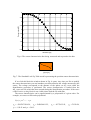
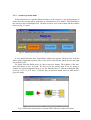
A schematic diagram of the laboratory set-up is shown in Fig. 1.
Electromagnet
PC
Sensor
Sphere
Frame
RT-DAC4/PCI
board
Power
supply
Fig. 1. MLS laboratory set-up
MLS User’s Manual
-3-