1
SAFETY PRECAUTIONS
(Read these precautions before using this product.)
Before using this product, please read this manual and the relevant manuals carefully and pay full attention
to safety to handle the product correctly.
The precautions given in this manual are concerned with this product only. For the safety precautions of the
programmable controller system, refer to the user's manual for the CPU module used.
In this manual, the safety precautions are classified into two levels: "
WARNING" and "
CAUTION".
WARNING
Indicates that incorrect handling may cause hazardous conditions,
resulting in death or severe injury.
CAUTION
Indicates that incorrect handling may cause hazardous conditions,
resulting in minor or moderate injury or property damage.
Under some circumstances, failure to observe the precautions given under "
CAUTION" may lead to
serious consequences.
Observe the precautions of both levels because they are important for personal and system safety.
Make sure that the end users read this manual and then keep the manual in a safe place for future
reference.
[Design Precautions]
WARNING
● In the case of a communication failure in the network, data in the master module are held. Check Data
link status (each station) (SW00B0 to SW00B7) and configure an interlock circuit in the program to
ensure that the entire system will operate safely.
● When the module is disconnected due to a communication failure in the network or the CPU module is
in the STOP status, all outputs are held or turned off according to the parameter setting.
Configure an interlock circuit in the program to ensure that the entire system will always operate
safely even in such a case. If not, an accident may occur due to an incorrect output or malfunction.
● Outputs may remain on or off due to a failure of the module. Configure an external circuit for
monitoring output signals that could cause a serious accident.
● Do not use any "use prohibited" signals as a remote input or output signal. These signals are reserved
for system use. Do not write any data to the "use prohibited" area in the remote register. If these
operations are performed, correct operation of the module cannot be guaranteed.
1
[Design Precautions]
CAUTION
● Do not install the communication cables together with the main circuit lines or power cables. Keep a
distance of 100mm or more between them. Failure to do so may result in malfunction due to noise.
● Do not install the control lines together with the main circuit lines or power cables. Keep a distance of
150mm or more between them. Failure to do so may result in malfunction due to noise.
[Installation Precautions]
WARNING
● Shut off the external power supply (all phases) used in the system before mounting or removing a
module. Failure to do so may result in electric shock or cause the module to fail or malfunction.
[Installation Precautions]
CAUTION
● Use the module in an environment that meets the general specifications in the user's manual for the
module. Failure to do so may result in electric shock, fire, malfunction, or damage to or deterioration of
the product.
● Do not directly touch any conductive parts and electronic components of the module. Doing so can
cause malfunction or failure of the module.
● Securely fix the module with a DIN rail.
● After the first use of the extension module, do not connect/disconnect the module more than 50 times
(in accordance with IEC 61131-2).
● To connect an extension module to a main module, engage the respective connectors and securely
lock the module joint levers. Incorrect connection may cause malfunction, failure, or drop of the
module.
● Securely connect the cable connectors. Poor contact may cause malfunction.
2
[Wiring Precautions]
WARNING
● Shut off the external power supply (all phases) used in the system before wiring. Failure to do so may
result in electric shock or cause the module to fail or malfunction.
[Wiring Precautions]
CAUTION
● Ground the shield cable for the pulse input on the encoder side (relay box) with a ground resistance of
100 or less. Failure to do so may cause malfunction.
● Individually ground the FG terminal of the programmable controller with a ground resistance of 100
or less. Failure to do so may result in electric shock or malfunction.
● Check the rated voltage and terminal layout before wiring to the module, and connect the cables
correctly. Connecting a power supply with a different voltage rating or incorrect wiring may cause a fire
or failure.
● Prevent foreign matter such as dust or wire chips from entering the module. Such foreign matter can
cause a fire, failure, or malfunction.
● Place the cables in a duct or clamp them. If not, dangling cable may swing or inadvertently be pulled,
resulting in damage to the module or cables or malfunction due to poor contact.
● Do not install the communication cables together with the main circuit lines or power cables. Keep a
distance of 100mm or more between them. Failure to do so may result in malfunction due to noise.
● Do not install the control lines together with the main circuit lines or power cables. Keep a distance of
150mm or more between them. Failure to do so may result in malfunction due to noise.
● When disconnecting the cable from the module, do not pull the cable by the cable part. For the cable
with connector, hold the connector part of the cable. For the cable connected to the terminal block,
loosen the terminal screw. Pulling the cable connected to the module may result in malfunction or
damage to the module or cable.
● When an overcurrent caused by an error of an external device or a failure of the programmable
controller flows for a long time, it may cause smoke and fire. To prevent this, configure an external
safety circuit, such as a fuse.
● Connectors for external devices must be crimped with the tool specified by the manufacturer, or must
be correctly soldered. Securely connect the connector to the module.
● Mitsubishi programmable controllers must be installed in control panels. Wiring and replacement of a
module must be performed by qualified maintenance personnel with knowledge of protection against
electric shock. For wiring methods, refer to "INSTALLATION AND WIRING" in this manual.
3
[Startup and Maintenance Precautions]
WARNING
● Do not touch any terminal while power is on. Doing so will cause electric shock or malfunction.
● Shut off the external power supply (all phases) used in the system before cleaning the module or
retightening the terminal block screws or connector screws. Failure to do so may cause the module to
fail or malfunction.
[Startup and Maintenance Precautions]
CAUTION
● Do not disassemble or modify the module. Doing so may cause failure, malfunction, injury, or a fire.
● Do not drop or apply strong shock to the module. Doing so may damage the module.
● Shut off the external power supply (all phases) used in the system before mounting or removing a
module. Failure to do so may cause the module to fail or malfunction.
● Before handling the module or the cable to be connected to the module, touch a conducting object
such as a grounded metal to discharge the static electricity from the human body. Failure to do so may
cause the module to fail or malfunction.
● Startup and maintenance of a control panel must be performed by qualified maintenance personnel
with knowledge of protection against electric shock. Lock the control panel so that only qualified
maintenance personnel can operate it.
[Disposal Precautions]
CAUTION
● When disposing of this product, treat it as industrial waste.
4
CONDITIONS OF USE FOR THE PRODUCT
(1) Mitsubishi programmable controller ("the PRODUCT") shall be used in conditions;
i) where any problem, fault or failure occurring in the PRODUCT, if any, shall not lead to any major
or serious accident; and
ii) where the backup and fail-safe function are systematically or automatically provided outside of
the PRODUCT for the case of any problem, fault or failure occurring in the PRODUCT.
(2) The PRODUCT has been designed and manufactured for the purpose of being used in general
industries.
MITSUBISHI SHALL HAVE NO RESPONSIBILITY OR LIABILITY (INCLUDING, BUT NOT
LIMITED TO ANY AND ALL RESPONSIBILITY OR LIABILITY BASED ON CONTRACT,
WARRANTY, TORT, PRODUCT LIABILITY) FOR ANY INJURY OR DEATH TO PERSONS OR
LOSS OR DAMAGE TO PROPERTY CAUSED BY the PRODUCT THAT ARE OPERATED OR
USED IN APPLICATION NOT INTENDED OR EXCLUDED BY INSTRUCTIONS, PRECAUTIONS,
OR WARNING CONTAINED IN MITSUBISHI'S USER, INSTRUCTION AND/OR SAFETY
MANUALS, TECHNICAL BULLETINS AND GUIDELINES FOR the PRODUCT.
("Prohibited Application")
Prohibited Applications include, but not limited to, the use of the PRODUCT in;
• Nuclear Power Plants and any other power plants operated by Power companies, and/or any
other cases in which the public could be affected if any problem or fault occurs in the PRODUCT.
• Railway companies or Public service purposes, and/or any other cases in which establishment of
a special quality assurance system is required by the Purchaser or End User.
• Aircraft or Aerospace, Medical applications, Train equipment, transport equipment such as
Elevator and Escalator, Incineration and Fuel devices, Vehicles, Manned transportation,
Equipment for Recreation and Amusement, and Safety devices, handling of Nuclear or
Hazardous Materials or Chemicals, Mining and Drilling, and/or other applications where there is a
significant risk of injury to the public or property.
Notwithstanding the above, restrictions Mitsubishi may in its sole discretion, authorize use of the
PRODUCT in one or more of the Prohibited Applications, provided that the usage of the PRODUCT
is limited only for the specific applications agreed to by Mitsubishi and provided further that no
special quality assurance or fail-safe, redundant or other safety features which exceed the general
specifications of the PRODUCTs are required. For details, please contact the Mitsubishi
representative in your region.
5
INTRODUCTION
Thank you for purchasing the CC-Link IE Field Network high-speed counter module (hereafter abbreviated as highspeed counter module).
This manual describes the operating procedure, system configuration, parameter settings, functions, and
troubleshooting of the high-speed counter module.
Before using this product, please read this manual and the relevant manuals carefully and develop familiarity with the
functions and performance of the high-speed counter module to handle the product correctly.
When applying the program examples introduced in this manual to an actual system, ensure the applicability and
confirm that it will not cause system control problems.
Target module: NZ2GFCF-D62PD2
Remark
Unless otherwise specified, this manual describes the program examples in which the remote I/O signals and remote
registers are assigned for a high-speed counter module as follows.
• Remote input signal: RX00 to RX4F
• Remote output signal: RY00 to RY4F
• Remote register: RWr0 to RWr3F, RWw0 to RWw3F
For the assignment of remote I/O signals and remote registers, refer to the following.
User's manual for the master/local module used
6
RELEVANT MANUALS
(1) CC-Link IE Field Network (relevant) manuals
When using the CC-Link IE Field Network for the first time, refer to CC-Link IE Field Network Master/Local
Module User's Manual or Simple Motion Module User's Manual first. The following shows the structure of the CCLink IE Field Network manuals.
Manual name
Description
<manual number (model code)>
MELSEC-Q CC-Link IE Field Network Master/Local Module User's
Manual
<SH-080917ENG, 13JZ47>
MELSEC-L CC-Link IE Field Network Master/Local Module User's
Manual
<SH-080972ENG, 13JZ54>
MELSEC-Q QD77GF Simple Motion Module User's Manual (Network)
<IB-0300203, 1XB957>
Overview of the CC-Link IE Field Network, and specifications,
procedures before operation, system configuration, installation,
wiring, settings, functions, programming, and troubleshooting of
the QJ71GF11-T2
Overview of the CC-Link IE Field Network, and specifications,
procedures before operation, system configuration, installation,
wiring, settings, functions, programming, and troubleshooting of
the LJ71GF11-T2
Functions, programming, and troubleshooting for CC-Link IE
Field Network of the QD77GF16
Specifications of the QD77GF16 and information on how to
MELSEC-Q QD77GF Simple Motion Module User's Manual (Positioning
establish a system, maintenance and inspection, and
Control)
troubleshooting.
<IB-0300202, 1XB956>
Functions, programming and buffer memory for the positioning
control of the QD77GF16
(2) Operating manual
Manual name
Description
<manual number (model code)>
GX Works2 Version 1 Operating Manual (Common)
System configuration, parameter settings, and online
operations of GX Works2, which are common to Simple projects
<SH-080779ENG, 13JU63>
and Structured projects
7
CONTENTS
CONTENTS
SAFETY PRECAUTIONS . . . . . . . . . . . . . . . . . . . . . . . . . . . . . . . . . . . . . . . . . . . . . . . . . . . . . . . . . . . . . 1
CONDITIONS OF USE FOR THE PRODUCT . . . . . . . . . . . . . . . . . . . . . . . . . . . . . . . . . . . . . . . . . . . . . 5
INTRODUCTION . . . . . . . . . . . . . . . . . . . . . . . . . . . . . . . . . . . . . . . . . . . . . . . . . . . . . . . . . . . . . . . . . . . . 6
RELEVANT MANUALS . . . . . . . . . . . . . . . . . . . . . . . . . . . . . . . . . . . . . . . . . . . . . . . . . . . . . . . . . . . . . . . 7
MANUAL PAGE ORGANIZATION . . . . . . . . . . . . . . . . . . . . . . . . . . . . . . . . . . . . . . . . . . . . . . . . . . . . . . 12
TERM. . . . . . . . . . . . . . . . . . . . . . . . . . . . . . . . . . . . . . . . . . . . . . . . . . . . . . . . . . . . . . . . . . . . . . . . . . . . 13
PACKING LIST . . . . . . . . . . . . . . . . . . . . . . . . . . . . . . . . . . . . . . . . . . . . . . . . . . . . . . . . . . . . . . . . . . . . 15
CHAPTER 1 HIGH-SPEED COUNTER MODULE
16
1.1
Application . . . . . . . . . . . . . . . . . . . . . . . . . . . . . . . . . . . . . . . . . . . . . . . . . . . . . . . . . . . . . . . . 17
1.2
Features . . . . . . . . . . . . . . . . . . . . . . . . . . . . . . . . . . . . . . . . . . . . . . . . . . . . . . . . . . . . . . . . . . 18
CHAPTER 2 PART NAMES
23
CHAPTER 3 SPECIFICATIONS
27
3.1
3.2
General Specifications . . . . . . . . . . . . . . . . . . . . . . . . . . . . . . . . . . . . . . . . . . . . . . . . . . . . . . . 27
Performance Specifications . . . . . . . . . . . . . . . . . . . . . . . . . . . . . . . . . . . . . . . . . . . . . . . . . . . 29
3.2.1
The input waveform and the phase difference between phase A pulse and phase B pulse
. . . . . . . . . . . . . . . . . . . . . . . . . . . . . . . . . . . . . . . . . . . . . . . . . . . . . . . . . . . . . 32
3.3
Calculating Current Consumption. . . . . . . . . . . . . . . . . . . . . . . . . . . . . . . . . . . . . . . . . . . . . . . 34
3.4
Function List . . . . . . . . . . . . . . . . . . . . . . . . . . . . . . . . . . . . . . . . . . . . . . . . . . . . . . . . . . . . . . . 35
3.5
List of Remote I/O Signals . . . . . . . . . . . . . . . . . . . . . . . . . . . . . . . . . . . . . . . . . . . . . . . . . . . . 38
3.6
List of Remote Register . . . . . . . . . . . . . . . . . . . . . . . . . . . . . . . . . . . . . . . . . . . . . . . . . . . . . . 42
3.7
List of Remote Buffer Memory . . . . . . . . . . . . . . . . . . . . . . . . . . . . . . . . . . . . . . . . . . . . . . . . . 45
CHAPTER 4 THE PROCEDURE BEFORE OPERATION
55
CHAPTER 5 SYSTEM CONFIGURATION
57
5.1
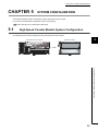
High-Speed Counter Module System Configuration . . . . . . . . . . . . . . . . . . . . . . . . . . . . . . . . . 57
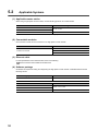
5.2
Applicable Systems . . . . . . . . . . . . . . . . . . . . . . . . . . . . . . . . . . . . . . . . . . . . . . . . . . . . . . . . . 58
CHAPTER 6 INSTALLATION AND WIRING
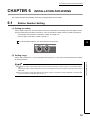
6.1
Station Number Setting. . . . . . . . . . . . . . . . . . . . . . . . . . . . . . . . . . . . . . . . . . . . . . . . . . . . . . . 59
6.2
Installation Environment and Installation Position . . . . . . . . . . . . . . . . . . . . . . . . . . . . . . . . . . 60
6.3
6.2.1
Installation environment . . . . . . . . . . . . . . . . . . . . . . . . . . . . . . . . . . . . . . . . . . . . . . . . . . . . . 60
6.2.2
Installation position. . . . . . . . . . . . . . . . . . . . . . . . . . . . . . . . . . . . . . . . . . . . . . . . . . . . . . . . . 60
6.2.3
Installation direction . . . . . . . . . . . . . . . . . . . . . . . . . . . . . . . . . . . . . . . . . . . . . . . . . . . . . . . . 61
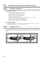
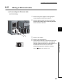
Installation. . . . . . . . . . . . . . . . . . . . . . . . . . . . . . . . . . . . . . . . . . . . . . . . . . . . . . . . . . . . . . . . . 62
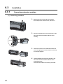
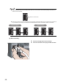
6.3.1
Connecting extension modules . . . . . . . . . . . . . . . . . . . . . . . . . . . . . . . . . . . . . . . . . . . . . . . 62
6.3.2
Mounting the modules on a DIN rail. . . . . . . . . . . . . . . . . . . . . . . . . . . . . . . . . . . . . . . . . . . . 64
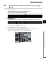
6.4
Wiring with Terminal Block for Module Power Supply and FG . . . . . . . . . . . . . . . . . . . . . . . . . 67
6.5
Wiring of Ethernet Cable. . . . . . . . . . . . . . . . . . . . . . . . . . . . . . . . . . . . . . . . . . . . . . . . . . . . . . 69
6.6
Wiring of Connectors for External Devices . . . . . . . . . . . . . . . . . . . . . . . . . . . . . . . . . . . . . . . . 72
6.6.1
8
59
Wiring precautions . . . . . . . . . . . . . . . . . . . . . . . . . . . . . . . . . . . . . . . . . . . . . . . . . . . . . . . . . 72
6.6.2
Connectors for external devices. . . . . . . . . . . . . . . . . . . . . . . . . . . . . . . . . . . . . . . . . . . . . . . 74
6.6.3
I/O interfaces with external devices . . . . . . . . . . . . . . . . . . . . . . . . . . . . . . . . . . . . . . . . . . . . 75
6.6.4
Encoders that can be connected . . . . . . . . . . . . . . . . . . . . . . . . . . . . . . . . . . . . . . . . . . . . . . 79
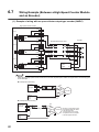
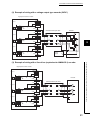
6.7
Wiring Example (Between a High-Speed Counter Module and an Encoder) . . . . . . . . . . . . . . 80
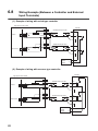
6.8
Wiring Example (Between a Controller and External Input Terminals) . . . . . . . . . . . . . . . . . . . 82
6.9
Wiring Example (with Coincidence Output Terminals) . . . . . . . . . . . . . . . . . . . . . . . . . . . . . . . 83
CHAPTER 7 VARIOUS SETTINGS
7.1
7.2
7.3
84
Parameter Setting. . . . . . . . . . . . . . . . . . . . . . . . . . . . . . . . . . . . . . . . . . . . . . . . . . . . . . . . . . . 84
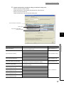
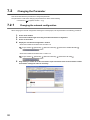
Changing the Parameter. . . . . . . . . . . . . . . . . . . . . . . . . . . . . . . . . . . . . . . . . . . . . . . . . . . . . . 92
7.2.1
Changing the network configuration. . . . . . . . . . . . . . . . . . . . . . . . . . . . . . . . . . . . . . . . . . . . 92
7.2.2
Changing the parameter without changing the network configuration . . . . . . . . . . . . . . . . . . 96
Operation Mode List . . . . . . . . . . . . . . . . . . . . . . . . . . . . . . . . . . . . . . . . . . . . . . . . . . . . . . . . . 99
CHAPTER 8 FUNCTIONS
101
8.1
Mode Shift at Power-on . . . . . . . . . . . . . . . . . . . . . . . . . . . . . . . . . . . . . . . . . . . . . . . . . . . . . 101
8.2
Drive Mode Switch . . . . . . . . . . . . . . . . . . . . . . . . . . . . . . . . . . . . . . . . . . . . . . . . . . . . . . . . . 102
8.3
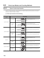
Pulse Input Modes and Counting Methods. . . . . . . . . . . . . . . . . . . . . . . . . . . . . . . . . . . . . . . 104
8.4
8.5
8.3.1
Types of pulse input modes . . . . . . . . . . . . . . . . . . . . . . . . . . . . . . . . . . . . . . . . . . . . . . . . . 104
8.3.2
Counting method setting . . . . . . . . . . . . . . . . . . . . . . . . . . . . . . . . . . . . . . . . . . . . . . . . . . . 106
Counter Format Selection. . . . . . . . . . . . . . . . . . . . . . . . . . . . . . . . . . . . . . . . . . . . . . . . . . . . 107
8.4.1
Linear counter function. . . . . . . . . . . . . . . . . . . . . . . . . . . . . . . . . . . . . . . . . . . . . . . . . . . . . 107
8.4.2
Ring counter function . . . . . . . . . . . . . . . . . . . . . . . . . . . . . . . . . . . . . . . . . . . . . . . . . . . . . . 109
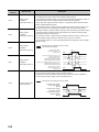
Comparison Output Function . . . . . . . . . . . . . . . . . . . . . . . . . . . . . . . . . . . . . . . . . . . . . . . . . 114
8.5.1
Operation overview of the coincidence output function and the cam switch function . . . . . 114
8.5.2
Coincidence output function. . . . . . . . . . . . . . . . . . . . . . . . . . . . . . . . . . . . . . . . . . . . . . . . . 115
8.5.3
Preset/replace (at coincidence output) function . . . . . . . . . . . . . . . . . . . . . . . . . . . . . . . . . . 126
8.5.4
Cam switch function . . . . . . . . . . . . . . . . . . . . . . . . . . . . . . . . . . . . . . . . . . . . . . . . . . . . . . . 129
8.6
Preset/replace Function . . . . . . . . . . . . . . . . . . . . . . . . . . . . . . . . . . . . . . . . . . . . . . . . . . . . . 134
8.7
Latch Counter Function by Latch Counter Input Terminal . . . . . . . . . . . . . . . . . . . . . . . . . . . 139
8.8
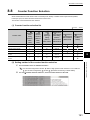
Counter Function Selection . . . . . . . . . . . . . . . . . . . . . . . . . . . . . . . . . . . . . . . . . . . . . . . . . . 141
8.9
Count Disable Function . . . . . . . . . . . . . . . . . . . . . . . . . . . . . . . . . . . . . . . . . . . . . . . . . . . . . 143
8.10
Latch Counter Function (Counter Function Selection) . . . . . . . . . . . . . . . . . . . . . . . . . . . . . . 145
8.11
Sampling Counter Function . . . . . . . . . . . . . . . . . . . . . . . . . . . . . . . . . . . . . . . . . . . . . . . . . . 148
8.12
Periodic Pulse Counter Function . . . . . . . . . . . . . . . . . . . . . . . . . . . . . . . . . . . . . . . . . . . . . . 151
8.13
Count Disable/preset/replace Function. . . . . . . . . . . . . . . . . . . . . . . . . . . . . . . . . . . . . . . . . . 154
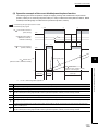
8.14
Latch Counter/preset/replace Function. . . . . . . . . . . . . . . . . . . . . . . . . . . . . . . . . . . . . . . . . . 157
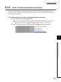
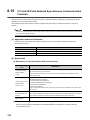
8.15
CC-Link IE Field Network Synchronous Communication Function. . . . . . . . . . . . . . . . . . . . . 160
8.16
Frequency Measurement Function . . . . . . . . . . . . . . . . . . . . . . . . . . . . . . . . . . . . . . . . . . . . . 163
8.17
Rotation Speed Measurement Function . . . . . . . . . . . . . . . . . . . . . . . . . . . . . . . . . . . . . . . . . 167
8.18
Pulse Measurement Function . . . . . . . . . . . . . . . . . . . . . . . . . . . . . . . . . . . . . . . . . . . . . . . . . 171
8.19
PWM Output Function . . . . . . . . . . . . . . . . . . . . . . . . . . . . . . . . . . . . . . . . . . . . . . . . . . . . . . 175
8.20
Output HOLD/CLEAR Setting Function . . . . . . . . . . . . . . . . . . . . . . . . . . . . . . . . . . . . . . . . . 182
8.21
Cyclic Data Update Watch Function . . . . . . . . . . . . . . . . . . . . . . . . . . . . . . . . . . . . . . . . . . . . 183
9
8.22
Error Notification Function . . . . . . . . . . . . . . . . . . . . . . . . . . . . . . . . . . . . . . . . . . . . . . . . . . . 184
8.23
Function at the Extension Module Installation . . . . . . . . . . . . . . . . . . . . . . . . . . . . . . . . . . . . 187
8.24
CC-Link IE Field Network Diagnostic Function. . . . . . . . . . . . . . . . . . . . . . . . . . . . . . . . . . . . 190
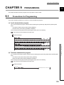
CHAPTER 9 PROGRAMMING
193
9.1
Precautions for Programming . . . . . . . . . . . . . . . . . . . . . . . . . . . . . . . . . . . . . . . . . . . . . . . . . 193
9.2
Procedure for Programming . . . . . . . . . . . . . . . . . . . . . . . . . . . . . . . . . . . . . . . . . . . . . . . . . . 195
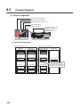
9.3
Program Example . . . . . . . . . . . . . . . . . . . . . . . . . . . . . . . . . . . . . . . . . . . . . . . . . . . . . . . . . . 196
CHAPTER 10 MAINTENANCE AND INSPECTION
219
CHAPTER 11 TROUBLESHOOTING
221
11.1
Checking for the Error Codes and the Warning Codes . . . . . . . . . . . . . . . . . . . . . . . . . . . . . 221
11.2
Error Code List . . . . . . . . . . . . . . . . . . . . . . . . . . . . . . . . . . . . . . . . . . . . . . . . . . . . . . . . . . . . 224
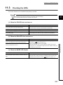
11.3
Checking the LEDs . . . . . . . . . . . . . . . . . . . . . . . . . . . . . . . . . . . . . . . . . . . . . . . . . . . . . . . . . 241
11.4
Unit Test . . . . . . . . . . . . . . . . . . . . . . . . . . . . . . . . . . . . . . . . . . . . . . . . . . . . . . . . . . . . . . . . . 244
11.5
Troubleshooting for Each Phenomenon . . . . . . . . . . . . . . . . . . . . . . . . . . . . . . . . . . . . . . . . . 245
11.5.1
When the setting on the operation mode setting is the normal mode . . . . . . . . . . . . . . . . . 245
11.5.2
When the setting on the operation mode setting is the frequency measurement mode . . . 251
11.5.3
When the setting on the operation mode setting is the rotation speed measurement mode
. . . . . . . . . . . . . . . . . . . . . . . . . . . . . . . . . . . . . . . . . . . . . . . . . . . . . . . . . . . . 251
11.5.4
When the setting on the operation mode setting is the pulse measurement mode . . . . . . . 251
11.5.5
When the setting on the operation mode setting is the PWM output mode . . . . . . . . . . . . . 252
11.5.6
When error codes/warning codes cannot be reset. . . . . . . . . . . . . . . . . . . . . . . . . . . . . . . . 252
11.5.7
When parameters cannot be read or written with GX Works2 and CC-Link IE Field Network
diagnostics cannot be performed . . . . . . . . . . . . . . . . . . . . . . . . . . . . . . . . . . . . . . 253
APPENDICES
254
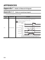
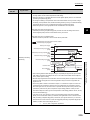
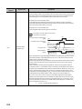
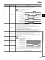
Appendix 1 Details of Remote I/O Signals . . . . . . . . . . . . . . . . . . . . . . . . . . . . . . . . . . . . . . . . . . . . 254
Appendix 1.1
Details of remote input signals . . . . . . . . . . . . . . . . . . . . . . . . . . . . . . . . . . 254
Appendix 1.2
Details of remote output signals . . . . . . . . . . . . . . . . . . . . . . . . . . . . . . . . . 267
Appendix 2 Details of Remote Registers . . . . . . . . . . . . . . . . . . . . . . . . . . . . . . . . . . . . . . . . . . . . . 273
Appendix 3 Details of Remote Buffer Memory Addresses . . . . . . . . . . . . . . . . . . . . . . . . . . . . . . . . 285
Appendix 4 Internal Control Cycle and Response Delay Time . . . . . . . . . . . . . . . . . . . . . . . . . . . . 302
Appendix 5 EMC and Low Voltage Directives . . . . . . . . . . . . . . . . . . . . . . . . . . . . . . . . . . . . . . . . . 307
Appendix 5.1
Measures to comply with the EMC directive . . . . . . . . . . . . . . . . . . . . . . . . . 307
Appendix 5.2
Requirements to compliance with the low voltage directive . . . . . . . . . . . . . . . . 312
Appendix 6 Checking Serial Number and Function Version . . . . . . . . . . . . . . . . . . . . . . . . . . . . . . 313
Appendix 7 Addition and Change of Functions . . . . . . . . . . . . . . . . . . . . . . . . . . . . . . . . . . . . . . . . 314
Appendix 7.1
Additional function . . . . . . . . . . . . . . . . . . . . . . . . . . . . . . . . . . . . . . . . . . 314
Appendix 7.2
Change of function . . . . . . . . . . . . . . . . . . . . . . . . . . . . . . . . . . . . . . . . . . 314
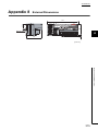
Appendix 8 External Dimensions . . . . . . . . . . . . . . . . . . . . . . . . . . . . . . . . . . . . . . . . . . . . . . . . . . . 315
INDEX
10
316
REVISIONS . . . . . . . . . . . . . . . . . . . . . . . . . . . . . . . . . . . . . . . . . . . . . . . . . . . . . . . . . . . . . . . . . . . . . . 320
WARRANTY . . . . . . . . . . . . . . . . . . . . . . . . . . . . . . . . . . . . . . . . . . . . . . . . . . . . . . . . . . . . . . . . . . . . . 321
11
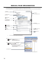
MANUAL PAGE ORGANIZATION
In this manual, pages are organized and the symbols are used as shown below.
The following illustration is for explanation purpose only, and should not be referred to as an actual documentation
"" is used for
screen names and items.
The chapter of
the current page is shown.
shows operating
procedures.
shows mouse
operations.*1
[ ] is used for items
in the menu bar and
the project window.
The section of
the current page is shown.
Ex. shows setting or
operating examples.
shows reference
manuals.
shows notes that
requires attention.
shows
reference pages.
shows useful
information.
*1
The mouse operation example is provided below.
Menu bar
Ex.
[Online]
[Write to PLC...]
Select [Online] on the menu bar,
and then select [Write to PLC...].
A window selected in the view selection area is displayed.
Ex.
[Parameter]
Project window
[PLC Parameter]
Select [Project] from the view selection
area to open the Project window.
In the Project window, expand [Parameter] and
select [PLC Parameter].
View selection area
12
TERM
Unless otherwise specified, this manual uses the following terms.
Term
CC-Link IE Field Network
Description
A high-speed and large-capacity open field network that is based on Ethernet (1000BASE-T)
GX Works2
The product name of the software package for the MELSEC programmable controllers
REMFR
The abbreviation for ZP.REMFR.
This dedicated instruction is used in programs of the master/local module.
REMTO
The abbreviation for ZP.REMTO.
This dedicated instruction is used in programs of the master/local module.
Intelligent device station
A station that deals with bit data and word data.
The station can communicate with the master station and other local stations. The station cannot
communicate with other remote I/O stations, remote device stations and intelligent device stations.
The station can perform the cyclic transmission and transient transmission.
Cyclic transmission
A function by which data are periodically exchanged among stations on the same network using link
devices (RX, RY, RWw, and RWr)
Simple motion module
The abbreviation for the QD77GF16 simple motion module
Slave station
A generic term for stations other than a master station: local station, remote I/O station, remote
device station, and intelligent device station
Data link
A generic term for cyclic transmission and transient transmission
Transient transmission
A function of communication with another station, which is used when requested by a dedicated
instruction or GX Works2
Network module
A generic term for the following modules:
• CC-Link IE Field Network module
• CC-Link IE Controller Network module
• Ethernet interface module
• MELSECNET/H module
• MELSECNET/10 module
Buffer memory
A memory in an intelligent function module, where data (such as setting values and monitoring
values) are stored
Programming tool
Another term for GX Works2
Master/local module
A generic term for the CC-Link IE Field Network master/local module
Master station
A station that controls CC-Link IE Field Network. The station can communicate with all stations.
Only one master station can be used in a network.
The station can perform the cyclic transmission and transient transmission.
Remote I/O station
A station that deals with bit data.
The station can communicate with the master station and other local stations. The station cannot
communicate with other remote I/O stations, remote device stations and intelligent device stations.
The station can perform the cyclic transmission.
Remote device station
A station that deals with bit data and word data.
The station can communicate with the master station and other local stations. The station cannot
communicate with other remote I/O stations, remote device stations and intelligent device stations.
The station can perform the cyclic transmission.
Remote buffer memory
Buffer memory in a remote device station
Remote register (RWr)
Word data input from a slave station to the master station (For some areas in a local station, data are
output in the opposite direction.)
Remote register (RWw)
Word data output from the master station to a slave station (For some areas in a local station, data
are output in the opposite direction.)
User's manual for the master/local module used
User's manual for the master/local module used
Remote output (RY)
Bit data output from the master station to a slave station (For some areas in a local station, data are
output in the opposite direction.)
User's manual for the master/local module used
Remote input (RX)
Bit data input from a slave station to the master station (For some areas in a local station, data are
output in the opposite direction.)
Link device
A device (RX, RY, RWr, or RWw) in a module on CC-Link IE Field Network
User's manual for the master/local module used
13
Term
Description
Link special relay (SB)
Bit data that indicates the operating status and data link status of a module on CC-Link IE Field
Network
Link special register (SW)
Bit data that indicates the operating status and data link status of a module on CC-Link IE Field
Network
Routing
A process of selecting paths for communication with other networks.
On CC-Link IE Field Network, set a network route with the routing parameter in advance to
communicate with a station that is set a different network number.
A high-speed counter module does not need to set the routing parameter. Communications with
other networks are performed according to the routing parameters set to the master station.
Local station
A station that includes a CPU module and can communicate with the master station and other local
stations.
This station can create simplified CC-Link IE Controller Network by combining the master station
and other local stations.
The station can perform the cyclic transmission and transient transmission.
Disconnection
A process of stopping data link if a data link error occurs
Main module
A module with the CC-Link IE Field Network communication function, which can be used as a single
remote module.
High-speed counter module
The abbreviation for the CC-Link IE Field Network high-speed counter module
Dedicated instruction
An instruction that simplifies programming for using functions of intelligent function modules
Extension module
A remote module that does not support the CC-Link IE Field Network communication function. This
module cannot be used as a single module. However, connecting the module to the main module will
increase the number of I/O points per station.
Extension I/O module
A generic term for extension modules where a digital signal can be input or output
Relay station
A station that includes two or more network modules. Data are passed through this station to
stations on other networks.
Return
A process of restarting data link when a station recovers from an error
Reserved station
A station reserved for future use. This station is not actually connected, but counted as a connected
station.
14
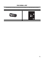
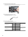
PACKING LIST
The following items are included in the package of this product. Before use, check that all the items are included.
High-speed counter module
Module
Before Using the Product
15
CHAPTER 1
HIGH-SPEED COUNTER MODULE
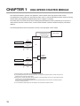
This chapter describes the operation, the application, and the features of the high-speed counter module.
The high-speed counter module is a remote device station of the CC-Link IE Field Network whose maximum counting
speed of input pulse is 8Mpps (with differential input and 4 multiples of 2 phases).
The module has two channels and functions including the preset/replace function by external input or input from a
master module, the latch counter function, counter function selection, external coincidence output by coincidence
detection.
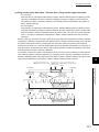
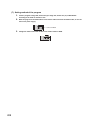
The following illustration shows the operation overview of the high-speed counter module.
Master module
3) Reading/writing of
remote I/O signals,
a remote register,
High-speed
and a remote buffer memory
counter module
Pulse
Encoder
Controller
1)
External control
signal
CH1
2)
Preset/replace
(phase Z) function
latch
Coincidence
output
4)
Pulse
Encoder
Controller
1)
External control
signal
(0 to 4 points)
shared with
CH1, CH2.
CH2
2)
Preset/replace
(phase Z) function
latch
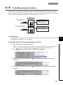
1) Pulses input to a high-speed counter module are counted.
2) The preset/replace function can be performed, counting can be paused, and a counter value can be
latched with an external control signal.
3) Status of the remote I/O signals, remote register, and remote buffer memory of a high-speed counter
module can be checked with the program.
Also, counting can be started/stopped; and the preset/replace function and the coincidence output
function can be performed.
4) The coincidence output signal can be output by the coincidence output function.
16
CHAPTER 1 HIGH-SPEED COUNTER MODULE
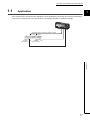
1.1
Application
1
This module performs controls which are applicable to various applications by executing various functions according to
count values of pulses input from the external device. The following describes an application example.
Temporarily stops the inverter. (Coincidence output)
Inverter
Encoder
(pulse generator)
CH1
Inverter
Encoder
CH2
(pulse generator)
1.1 Application
17
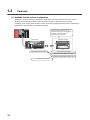
1.2
Features
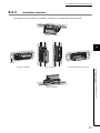
(1) Available flexible system configuration
Adopting the connection block type enables the combination of the main module and extension module.
Because various extension modules can be connected, a flexible configuration can be achieved.
In addition, a poor contact of the extension module can be found promptly because the main module always
monitors the connection status of the extension module.
Various extension modules can be
connected according to an application.
In addition, no wiring of wires or
Ethernet cables is required.
Main module
High-speed counter module
Extension module
Extension input module
Extension output module (sink type)
Extension output module (source type)
The combination is flexible.
18
CHAPTER 1 HIGH-SPEED COUNTER MODULE
1
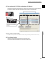
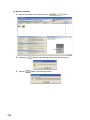
(2) Easy setting with CC IE Field configuration of GX Works2
Programming is reduced since the parameter can be configured on the window with the CC IE Field configuration
of GX Works2. In addition, setting status and operation status of modules can be checked easily.
Parameters for the NZ2GFCF-D62PD2
NZ2GFCF-D62PD2
Select
Parameters can be intuitively set
for the function to be used without
a manual.
Function name
Setting value
1.2 Features
(3) Easy station number setting
Because of the rotary switch on the front of the module, setting and checking the station number are easy.
(4) Error history function
The history of 15 errors and occurrence time can be stored in the module.
The error history helps the investigation for the cause when a problem occurs.
19
(5) Pulse measurement function
Pulses can be measured with 100ns measurement resolution. The pulse width (ON width/OFF width) can be
precisely measured. Various pulse measurement applications such as the workpiece length measurement or the
transport/processing speed management of various types of transport equipment and processing equipment are
available.
Example: Filling process (container type identification control)
Pulse
Light sensor
(6) Coincidence output function
This function compares a preset value with the input count value. If they match, the function outputs a signal and
thus the fixed-feed control is possible.
Control example: Drilling process (fixed-feed control)
driller
Counter input
Coincidence output
(inverter stop)
Encoder
Inverter
20
CHAPTER 1 HIGH-SPEED COUNTER MODULE
1
(7) Cam switch function
According to the input count present value, the ON/OFF status of output can be set for every preset point without
any program. More precise ON/OFF control is available without scan time effect.
An extension output module is required for using this function.
ON
Output 1
OFF
ON
Output 2
OFF
ON
Output 3
Count present value
OFF
1000
2000
3000
4000
5000
6000
7000
8000
(8) PWM output function
Up to 200kHz of the PWM waveform can be output. The duty ratio can be set by 0.1µs and this enables precise
output control. The PWM output function enables controls such as dimming control according to duty ratio
modification.
Lighting: dimmer
Lighting: brighter
Duty ratio: 50%
Duty ratio: 80%
1.2 Features
Example: Lighting control
Lighting can
be controlled by
changing
the duty ratio.
21
(9) CC-Link IE Field Network synchronous communication function
Using this function, the high-speed counter module updates the count value in synchronization with the operation
cycle of a simple motion module.
This enables the high-speed counter module to operate at the same timing of slave stations on the same
network.
22
CHAPTER 2 PART NAMES
CHAPTER 2
PART NAMES
2
This chapter describes the part names of the high-speed counter module.
*1
2)
1)
3)
4)
5)
6)
7)
*1
*1 Do not remove this seal because it is used for a maintenance purpose.
23
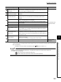
No.
Name
Description
A rotary switch for the following setting and test
1)
Station number setting
switch
• Station Number Setting (
• Unit Test (
Page 59, Section 6.1)
Page 244, Section 11.4)
When operating the station number setting switch, use a slotted screwdriver with 3.5mm or less width
of the tip.
PW LED (green)
Power supply ON
OFF
Power supply OFF
RUN LED (green)
Indicates the operating status of the module.
ON
Operating normally
OFF
When a major error occurs
MODE LED (green)
Indicates the mode status of the module.
ON
In online mode
Flashing
In unit test mode
OFF
At the unit test completion
D LINK LED (green)
Indicates the data communication status between the module and the master module.
ON
Data link in operation (cyclic transmission in progress)
Flashing
Data link in operation (cyclic transmission stopped)
OFF
Data link not performed (disconnected)
ERR. LED (red)
2)
Indicates the power supply status of the module.
ON
Indicates the error status of the module.
ON
A moderate error or major error has occurred.
Flashing
A minor error (warning) has occurred.
OFF
Operating normally
CH1A/B/Z LED
CH2A/B/Z LED
Indicates the input status of the pulse input terminals in phase A, B, and Z.
(green)
ON
At voltage application
OFF
At no voltage application
CH1FNC/LAT LED
CH2FNC/LAT LED
Indicates the input status of the function/latch counter input terminal.
(green)
ON
At voltage application
OFF
At no voltage application
EQU1 to EQU4 LED
(green)
24
Indicates the output status of the coincidence output 1 to 4 terminals (EQU1 to EQU4).
ON
Signal output ON
OFF
Signal output OFF
CHAPTER 2 PART NAMES
No.
Name
Description
PORT1 connector for CC-Link IE Field Network (RJ45 connector)
Connect an Ethernet cable. (
P1
Page 69, Section 6.5)
There are no restrictions on the connection order of the cables for the "P1" connector and "P2"
connector.
L ER
ON
LED
2
• The module has received abnormal data.
• The module is performing loopback.
• The module has received normal data.
(red)
OFF
LINK
ON
Linkup in progress
OFF
Linkdown in progress
• The module is not performing loopback.
LED
3)
(green)
PORT2 connector for CC-Link IE Field Network (RJ45 connector)
Connect an Ethernet cable. (
P2
Page 69, Section 6.5)
There are no restrictions on the connection order of the cables for the "P1" connector and "P2"
connector.
L ER
LED
(red)
LINK
LED
(green)
ON
OFF
(Same as the P1)
ON
OFF
(Same as the P1)
Terminal block for
4)
module power supply and
A terminal block to connect the module power supply (24VDC) and FG.
FG
5)
6)
7)
DIN rail hook
A hook to mount a module on a DIN rail
Connectors for external
Connectors for encoders, controllers, and others
devices (40 pins)
(For the terminal layouts, refer to
Extension connector cover
Page 75, Section 6.6.3.)
A cover to protect a connector of an extension module.
Do not remove the cover when an extension module is not connected to the connector.
When the phase Z of the encoder is connected to the phase Z pulse input terminal (Zn), a pulse is counted per rotation of the
encoder. Therefore, lighting of the LEDs may be missed.
25
(1) Module status and LED status
The following table lists the correspondence between the module status and the LED status.
Module status
Data link status
LED status
PW LED
RUN LED
MODE LED
D LINK LED
ERR. LED
Disconnecting
Disconnection
ON
ON
ON
OFF
OFF
Data link in operation
Data link in operation
ON
ON
ON
ON
OFF
Cyclic stop
ON
ON
ON
Flashing
OFF
Link stop
Cyclic stop
ON
ON
ON
Flashing
OFF
Communication error
Cyclic stop
ON
ON
ON
Flashing
OFF
Reserved station
specification in progress
Error
Warning
Major
ON
OFF
*1
*2
ON*3
Moderate
ON
ON
*1
*2
ON
Minor
ON
ON
*1
*2
Flashing
In progress
ON
ON
Flashing
OFF
OFF
ON
ON
OFF
OFF
OFF
ON
ON
OFF
OFF
ON
Normal
Unit test
completion
Abnormal
completion
*1
*2
*3
26
Either of ON or OFF.
Either of ON, Flashing, or OFF.
When the module is failed, the LED may not turn on.
CHAPTER 3 SPECIFICATIONS
CHAPTER 3
SPECIFICATIONS
This chapter describes the specifications of the high-speed counter module.
3.1
General Specifications
Item
3
Specifications
Operating
ambient
0 to 55°C
temperature
Storage ambient
-25 to 75°C
temperature
Operating
ambient humidity
5 to 95%RH, non-condensing
Storage ambient
humidity
Constant
Frequency
Compliant with
Vibration
JIS B 3502 and
resistance
IEC 61131-2
Operating
Half amplitude
5 to 8.4Hz
3.5mm
8.4 to 150Hz
9.8m/s2
Under continuous
5 to 8.4Hz
1.75mm
vibration
8.4 to 150Hz
4.9m/s2
Under
intermittent
vibration
Number of
sweeps
10 times each in
X, Y, and Z
directions
3.1 General Specifications
Shock resistance
acceleration
Compliant with JIS B 3502 and IEC 61131-2 (147m/s2, 3 times each in X, Y, and Z directions)
No corrosive gases
atmosphere
Operating
0 to 2000m
altitude*1
Installation
Inside a control panel*2
location
Overvoltage
II or less
category*3
Pollution
2 or less
degree*4
Equipment class
*1
*2
*3
*4
Class I
Do not use or store the high-speed counter module under pressure higher than the atmospheric pressure of altitude 0m.
Doing so may cause malfunction. When using the high-speed counter module under pressure, please consult your local
Mitsubishi representative.
If the environment satisfies the operating ambient temperature, operating ambient humidity and other conditions, the
module can be used even outside the control panel.
This indicates the section of the power supply to which the equipment is assumed to be connected between the public
electrical power distribution network and the machinery within premises.
Category II applies to equipment for which electrical power is supplied from fixed facilities. The surge voltage withstand
level for the equipment with the rated voltage of 300V or less is 2500V.
This index indicates the degree to which conductive material is generated in terms of the environment in which the
equipment is used.
Pollution degree 2 is when only non-conductive pollution occurs. A temporary conductivity caused by condensing must
be expected occasionally.
27
To use the high-speed counter module complying with the EMC Directive, refer to "EMC and Low Voltage Directives" in this
manual. (
28
Page 307, Appendix 5)
CHAPTER 3 SPECIFICATIONS
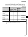
3.2
Performance Specifications
The following table shows the performance specifications of the high-speed counter module.
Item
Specifications
Station type
Remote device station
Availability of connecting extension module
setting*1
3
Connectable (Max. one module)
Differential input
DC input
1 multiple
10kpps/100kpps/200kpps/500kpps/1Mpps/2Mpps
10kpps/100kpps/200kpps
2 multiples
10kpps/100kpps/200kpps/500kpps/1Mpps/2Mpps/
4Mpps
10kpps/100kpps/200kpps
4 multiples
10kpps/100kpps/200kpps/500kpps/1Mpps/2Mpps/
4Mpps/8Mpps
10kpps/100kpps/200kpps
Counting speed switch
Number of channels
2 channels
Count input signal
Differential input
DC input
Phase
1-phase input (1 multiple/2 multiples), 2-phase input (1 multiple/2 multiples/4 multiples), CW/CCW
Signal level (A, B)
EIA Standards RS-422-A, differential line driver
level (AM26LS31 [manufactured by Texas
Instruments] or equivalent)
Counter
Counting speed (Maximum)*2*3
5/24VDC, 4 to 8mA
Differential input
DC input
8Mpps (4 multiples of 2 phases)
200kpps
Counting range
32-bit signed binary (-2147483648 to 2147483647)
Format
Count, subtraction count
Linear counter format, ring counter format
Preset/replace function, latch counter function
Minimum count pulse width (µs) (Duty ratio 50%)
1-phase input (1 multiple/2
multiples), CW/CCW
0.25 s 0.25 s
(Minimum pulse width in 2 multiples of 1 phase:
0.25µs)
0.5 s
0.25 s
0.25 s
2.5 s
2.5 s
(Minimum pulse width in 2 multiples of 1 phase:
2.5µs)
20 s
10 s
10 s
2-phase input (1 multiple/2
multiples/4 multiples)
0.125 s
(Minimum pulse width in 4 multiples of 2 phases:
0.125µs)
Comparison range
Coincidence output
Coincidence
detection
Comparison
condition
Interrupt
5 s
(Minimum pulse width in 4 multiples of 2 phases:
5µs)
32-bit signed binary
Setting value < Count value
Setting value = Count value
Setting value > Count value
Within-range output
Setting value (lower limit value) Count value Setting value (upper limit value)
Out-of-range output
Count value < Setting value (lower limit value), Setting value (upper limit value) < Count value
None
29
3.2 Performance Specifications
5 s
0.5 s
Item
Differential input
DC input
Phase Z
EIA Standards RS-422-A, differential line driver
level (AM26LS31 [manufactured by Texas
Instruments] or equivalent): 2 points
5/24VDC, 4 to 8mA: 2 points
Function
5/24VDC, 7 to 12mA: 2 points
External input
External
output
Pulse
measurement
Cam switch
PWM output
Applicable
wire size
Specifications
Latch counter
5/24VDC, 7 to 12mA: 2 points
Coincidence output
Transistor (sink type) output: 4 points
5 to 24VDC 0.1A/point, 0.4A/common
Measurement item
Pulse width (ON width/OFF width)
Measurement resolution
100ns
Measurement points
2 points/channel
Number of output points
16 points
Number of steps per output point
Maximum 16 steps/point
Control cycle
0.5ms
Difference between each output
duration in a channel
Within the output response time of the extension output module
Output frequency range
DC and up to 200kHz
Duty ratio
Any ratio (Can be set by 0.1µs)
For external device connection
For power supply
0.088 to 0.3mm2 (28 to 22 AWG) (A6CON1 and A6CON4)
0.088 to 0.24mm2 (28 to 24 AWG) (A6CON2)
Core: 0.5 to 1.5mm2 (20 to 16 AWG)
Applicable connector for external wiring
A6CON1, A6CON2, A6CON4 (sold separately)
External power supply
24VDC (20.4 to 26.4VDC)
Current consumption: 220mA
Cyclic
transmission
RX/RY points
80 points + 16 points × number of extension modules
RWr/RWw points
64 points
Communication cable
An Ethernet cable that meets the 1000BASE-T standard:
Category 5e or higher (double shielded, STP), straight cable
External dimensions
133mm × 68mm × 50mm
Weight
0.25kg
External
connection
system
Communication part
RJ45 connector
Module power supply part
Terminal block for module power supply and FG
Tightening torque range for terminal screw (M2.5 screw): 0.5 to 0.6N•m
Applicable DIN rail
TH35-7.5Fe, TH35-7.5Al (compliant with IEC 60715)
TE 0.5-10 (Nichifu Co. Ltd.) [Applicable wire size: 0.5mm2]
TE 0.75-10 (Nichifu Co. Ltd.) [Applicable wire size: 0.75mm2]
Applicable
solderless
terminal
TE 1.0-10 (Nichifu Co. Ltd.) [Applicable wire size: 0.9 to 1.0mm2]
Terminal block for module power
supply and FG
TE 1.5-10 (Nichifu Co. Ltd.) [Applicable wire size: 1.25 to 1.5mm2]
AI 0.5-10WH (Phoenix Contact Co. Ltd.) [Applicable wire size: 0.5mm2]
AI 0.75-10GY (Phoenix Contact Co. Ltd.) [Applicable wire size: 0.75mm2]
AI 1-10RD (Phoenix Contact Co. Ltd.) [Applicable wire size: 1.0mm2]
AI 1.5-10BK (Phoenix Contact Co. Ltd.) [Applicable wire size: 1.5mm2]
30
CHAPTER 3 SPECIFICATIONS
*1
*2
*3
Counting speed setting can be done using the parameter setting. (
Page 84, Section 7.1)
Note that the count may be done incorrectly by inputting pulses whose phase difference is small between the phase A
pulse and phase B pulse. To check the input waveform of the phase A pulse and phase B pulse, or to check phase
difference between the phase A pulse and phase B pulse, refer to the following:
Page 32, Section 3.2.1
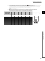
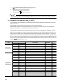
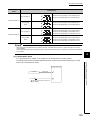
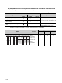
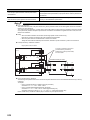
The counting speed is affected by the pulse rise/fall time. The applicable counting speed is listed below.
Note that the count may be done incorrectly by counting pulses with long rise/fall time.
Counting speed
switch setting
8Mpps
4Mpps
1Mpps
500kpps
200kpps
100kpps
10kpps
100kpps
10kpps
*Counting speed = 1/T (pps)
3
2Mpps
Rise/fall time
Both 1- and 2-phase inputs
t = 0.125µs
2Mpps
1Mpps
500kpps
200kpps
t = 0.25µs or less
1Mpps
1Mpps
500kpps
200kpps
100kpps
10kpps
t = 0.5µs or less
500kpps
500kpps
200kpps
100kpps
10kpps
t = 1.25µs or less
200kpps
200kpps
100kpps
10kpps
t = 2.5µs or less
100kpps
100kpps
10kpps
t = 25µs or less
10kpps
10kpps
t = 500µs
500pps
T
t
t
3.2 Performance Specifications
31
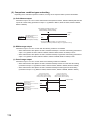
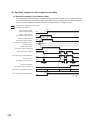
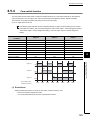
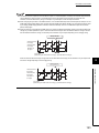
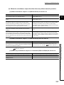
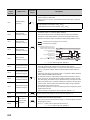
3.2.1
The input waveform and the phase difference between phase
A pulse and phase B pulse
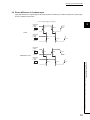
The count may be done incorrectly by inputting pulses whose phase difference is small between the phase A pulse
and phase B pulse in 2-phase input.
The following figures show the pulse waveform to be input and the phase difference between the phase A pulse and
phase B pulse. (Though the following are the cases for the differential input, they are also applied to the DC input.)
Though the following are the pulse waveform to be input and the phase difference measured at the maximum counting
speed of each pulse input condition, they are also applied to the case measured at under the maximum counting
speed.
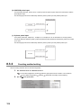
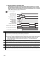
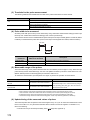
(1) Input waveform in 1-phase input
Input pulse waveform in 1-phase input must satisfy the condition shown below (the duty ratio is 50%).
t (= tH + tL)
tH, tL
0.5 s
0.25 s (= 0.5
t)
t
Differential
voltage
H level
0.1V
-0.1V
0.1V
L level
tH
32
tL
CHAPTER 3 SPECIFICATIONS
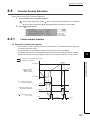
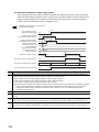
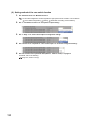
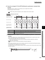
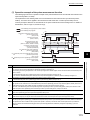
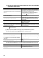
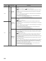
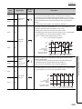
(2) Phase difference in 2-phase input
Input pulse waveform in 2-phase input must satisfy the above condition (the condition required for 1-phase input)
and the conditions shown below.
t1, t2, t3, t4
0.125 s (= 0.25
t)
3
Differential
voltage
H level
A
L level
Count
0.1V
-0.1V
0.1V
t2
t1
Differential
voltage
H level
0.1V
B
-0.1V
0.1V
L level
Differential
voltage
H level
A
Subtraction count
L level
-0.1V
0.1V
t3
t4
-0.1V
Differential
voltage
H level
0.1V
-0.1V
0.1V
3.2 Performance Specifications
3.2.1 The input waveform and the phase difference between phase A pulse and phase B pulse
B
L level
33
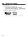
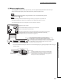
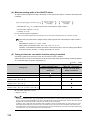
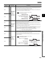
3.3
Calculating Current Consumption
The total current consumption of the modules is calculated by summing the module power supply current in the main
module and extension module.
The power supply current in the extension module must be within 30mA.
For the value of the module power supply current, refer to the specifications of each module.
• Performance specifications of the high-speed counter module (
• Performance specifications of extension I/O module (
Page 29, Section 3.2)
CC-Link IE Field Network Remote I/O Module
User's Manual)
The value of the module power supply current in the extension module described in the specifications is the value of
the module power supply current supplied from the main module.
High-speed counter module
NZ2GFCF-D62PD2
Module power supply current: 220mA
34
Extension module
+
NZ2EX2B1-16T
250mA
=
Module power supply current: 30mA
(Total current consumption)
CHAPTER 3 SPECIFICATIONS
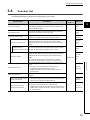
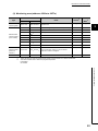
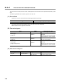
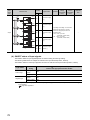
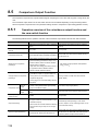
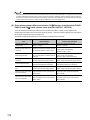
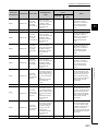
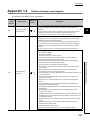
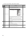
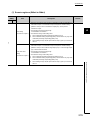
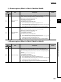
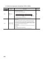
3.4
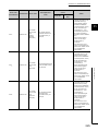
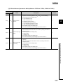
Function List
The following table lists the functions of the high-speed counter module.
Function name
Linear counter function
Ring counter function
Comparison output function
Description
Operation
mode*1
This function counts pulses between -2147483648 and
Page 107,
2147483647, and detects an overflow/underflow when the count
Section
value is outside the range.
8.4.1
Section
value and lower limit value of the ring counter.
8.4.2
This function compares the count value with the preset comparison
Page 114,
condition, and outputs ON/OFF signals when they match.
Section 8.5
Page 115,
coincidence detection point or a detection area and outputs
Section
ON/OFF signals from the coincidence output terminal when they
8.5.2
match.
Preset/replace (at
This function replaces the count value with any preset numerical
coincidence output) function
value at the rising edge of Coincidence output 1 and 2.
3
Page 109,
This function repeatedly counts pulses between the upper limit
This function compares the present count value with the preset
Coincidence output function
Reference
Page 126,
Section
8.5.3
This function compares the count value with the preset output
status (ON/OFF address) of the coincidence output, and outputs
Cam switch function
Page 129,
ON/OFF signals from the extension output module when they
match.
The points for ON/OFF switch can be used up to 16 points.
Normal mode
Section
8.5.4
An extension output module is required for using this function.
value.
Preset/replace function
This function can be used with either of the following.
• CH Preset/replace command (RY21, RY39)
Page 134,
Section 8.6
• CH Phase Z input terminal (Z1, Z2) of the connector for
external devices
Latch counter function
Latch counter function by latch
counter input terminal
This function acquires the count value and stores it in the remote
register.
This function stores the count value in the remote register.
• This function uses CH Latch counter input terminal (LATCH1,
LATCH2) of the connector for external devices.
Page 139,
Section 8.7
This function stores the count value in the remote register.
Latch counter function by
counter function selection
This function can be used with either of the following.
• CH Selected counter function start command (RY25, RY3D)
• CH Function input terminal (FUNC1, FUNC2) of the connector
Page 145,
Section 8.10
for external devices
35
3.4 Function List
This function replaces the count value with any preset numerical
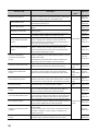
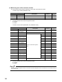
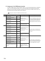
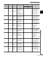
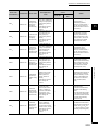
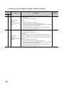
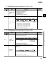
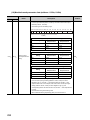
Function name
Description
Operation
mode*1
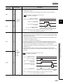
This function executes the counter function selection using both the
Counter function selection
Page 141,
program and CH Function input terminal (FUNC1, FUNC2) of the
Section 8.8
connector for external devices, or using either of them.
Count disable function
Latch counter function
Sampling counter function
Periodic pulse counter function
Reference
This function stops counting pulses while CH Count enable
Page 143,
command (RY24, RY3C) is on.
Section 8.9
This function acquires the count value and stores it in the remote
Page 145,
register.
Section 8.10
This function counts pulses that are input during the preset
Page 148,
sampling period.
Section 8.11
This function stores the present value and difference value to the
Page 151,
corresponding remote registers by the preset cycle time.
Section 8.12
According to the status change of CH Function input terminal
Normal mode
Count disable/preset/replace
(FUNC1, FUNC2) of the connector for external devices, this
Page 154,
function
function executes the count disable function and preset/replace
Section 8.13
function without switching the functions.
According to the status change of CH Function input terminal
Latch counter/preset/replace
(FUNC1, FUNC2) of the connector for external devices, this
Page 157,
function
function executes the latch counter function and preset/replace
Section 8.14
function without switching the functions.
With this function, CH Present value (RWr10 to RWr11, RWr28 to
CC-Link IE Field Network
RWr29) is updated in synchronization with the operation cycle of a
synchronous communication
simple motion module.
function
This enables the high-speed counter module to operate at the
Page 160,
Section 8.15
same timing of other slave stations on the same network.
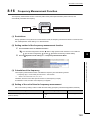
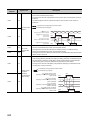
Frequency measurement function
This function counts the pulses of the pulse input terminals in
phase A and B, and automatically calculates the frequency.
Frequency
measurement
mode
Page 163,
Section 8.16
Rotation
Rotation speed measurement
This function counts the pulses of the pulse input terminals in
speed
Page 167,
function
phase A and B, and automatically calculates the rotation speed.
measurement
Section 8.17
mode
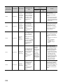
Pulse measurement function
PWM output function
Output HOLD/CLEAR setting
function
This function measures CH Function input terminal (FUNC1,
Pulse
FUNC2) or CH Latch counter input terminal (LATCH1, LATCH2)
measurement
of the connector for external devices, and calculates the ON width.
mode
This function outputs the specified PWM waveform from any
PWM output
Page 175,
coincidence output 1 to 4 terminals (EQU1 to EQU4).
mode
Section 8.19
This function sets the output status of the extension output module
Section 8.20
EQU4) and the cam switch function to HOLD or CLEAR.
Page 183,
cyclic transmission remains to be stopped over the set watch time,
Section 8.21
this function holds or clears the value which is output just before.
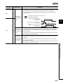
When a moderate error or a major error occurs in the high-speed
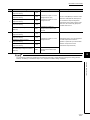
Error notification function
Section 8.18
Page 182,
(Y0 to YF) used as the output of Coincidence output (EQU1 to
This function monitors the cyclic data update interval. When the
Cyclic data update watch function
Page 171,
counter module, this function notifies the master station of the error
Common to all
using the remote register and the remote input signal.
modes
Page 184,
Section 8.22
One extension I/O module can be connected to one high-speed
Function at the extension module
installation
counter module.
The cam switch function can be used by connecting the extension
I/O module. In addition, functions unique to the extension I/O
Page 187,
Section 8.23
module can be used.
CC-Link IE Field Network diagnostic
With this function, whether any network error occurs or not can be
Page 190,
function
checked through GX Works2 connected to the CPU module.
Section 8.24
36
CHAPTER 3 SPECIFICATIONS
*1
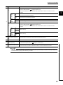
The operation mode can be set in the parameter setting. For details, refer to the following.
Page 84, Section 7.1
3
3.4 Function List
37
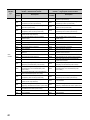
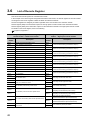
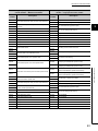
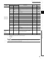
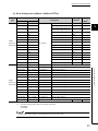
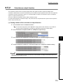
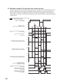
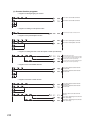
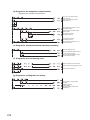
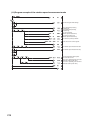
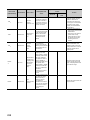
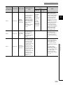
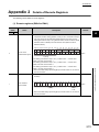
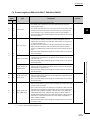
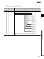
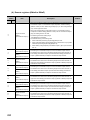
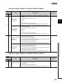
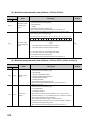
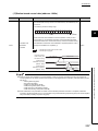
3.5
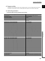
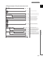
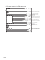
List of Remote I/O Signals
This section lists I/O signals for a master/local module.
In the example of the I/O signal assignment described in this section, the remote I/O signals of the main module are
assigned to the I/O numbers of RX0 to RX4F and RY0 to RY4F.
Remote input (RX) indicates the input signal from the high-speed counter module to the master/local module.
Remote output (RY) indicates the output signal from the master/local module to the high-speed counter module.
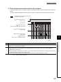
The remote I/O signals of the main module and extension module are assigned as shown below.
Main module
Module
Extension module 1
Remote input (RX)
Remote output (RY)
Main module
RX0 to RX4F
RY0 to RY4F
Extension module 1
RX50 to RX5F
RY50 to RY5F
For details on the remote I/O signals, refer to the following.
Page 254, Appendix 1
Remote input signal direction: High-speed counter
Remote output signal direction: Master/local
module Master/local module
module High-speed counter module
Module
type
Device
Description
number
Main
module
38
Device
Description
number
RX0
Use prohibited
RY0
Use prohibited
RX1
Use prohibited
RY1
Use prohibited
RX2
Use prohibited
RY2
Use prohibited
RX3
Use prohibited
RY3
Use prohibited
RX4
Use prohibited
RY4
Use prohibited
RX5
Use prohibited
RY5
Use prohibited
RX6
Use prohibited
RY6
Use prohibited
RX7
Warning status flag
RY7
Use prohibited
RX8
Initial data processing request flag
RY8
Initial data processing completion flag
RX9
Initial data setting completion flag
RY9
Initial data setting request flag
RXA
Error status flag
RYA
Use prohibited
RXB
Remote READY
RYB
Use prohibited
RXC
Use prohibited
RYC
Use prohibited
RXD
Use prohibited
RYD
Use prohibited
RXE
Use prohibited
RYE
Use prohibited
RXF
Use prohibited
RYF
Use prohibited
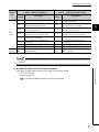
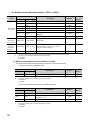
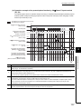
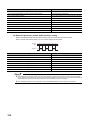
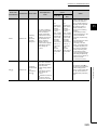
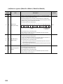
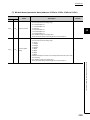
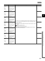
CHAPTER 3 SPECIFICATIONS
Remote input signal direction: High-speed counter
Remote output signal direction: Master/local
module Master/local module
module High-speed counter module
Module
type
Device
Description
number
Device
Description
number
RX10
Coincidence output 1
RY10
Reset command (Coincidence output 1)
RX11
Coincidence output 2
RY11
Reset command (Coincidence output 2)
RX12
Coincidence output 3
RY12
Reset command (Coincidence output 3)
RX13
Coincidence output 4
RY13
Reset command (Coincidence output 4)
RY14
Setting change request (Coincidence output 1)
RY15
Setting change request (Coincidence output 2)
RY16
Setting change request (Coincidence output 3)
RY17
Setting change request (Coincidence output 4)
RX14
RX15
RX16
RX17
Setting change completed
(Coincidence output 1)
Setting change completed
(Coincidence output 2)
Setting change completed
(Coincidence output 3)
Setting change completed
(Coincidence output 4)
RX18
Use prohibited
RY18
Use prohibited
RX19
Use prohibited
RY19
Use prohibited
RX1A
Use prohibited
RY1A
Use prohibited
RX1B
Use prohibited
RY1B
Use prohibited
RX1C
Use prohibited
RY1C
Use prohibited
RX1D
Use prohibited
RY1D
Use prohibited
RX1E
Use prohibited
RY1E
Use prohibited
RX1F
External power supply monitor state flag
(for extension output module)
RY1F
External power supply monitor request flag
(for extension output module)
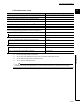
Use prohibited
Main
RX21
CH1 Preset/replace completion
RY21
CH1 Preset/replace command
module
RX22
Use prohibited
RY22
CH1 Count down command
CH1 External preset/replace (Z Phase) request
detection
RY23
CH1 Coincidence output enable command
CH1 External preset/replace (Z Phase) request
detection reset command
RX24
Use prohibited
RY24
CH1 Count enable command
RX25
CH1 Counter function detection
RY25
CH1 Selected counter function start command
RX26
CH1 Cam switch execute/PWM output
RY26
RX27
CH1 Setting change completed
(Sampling counter/Periodic pulse counter)
RY27
CH1 Update flag reset completed (Latch count
RX28
value/Sampling count value/Periodic pulse
RX2A
RX2B
RX2C
RX2D
CH1 Update flag (Latch count value/Sampling
count value/Periodic pulse count value)
CH1 Latch count value update flag reset
completed (Latch counter input terminal)
CH1 Latch count value update flag
(Latch counter input terminal)
CH1 Update flag reset completed (Measured
frequency value/Measured rotation speed value)
CH1 Update flag (Measured frequency
value/Measured rotation speed value)
output start command
CH1 Setting change request
(Sampling counter/Periodic pulse counter)
CH1 Update flag reset command (Latch count
RY28
count value)
RX29
CH1 Cam switch execute command/PWM
value/Sampling count value/Periodic pulse
count value)
RY29
RY2A
RY2B
RY2C
Use prohibited
CH1 Latch count value update flag reset
command (Latch counter input terminal)
Use prohibited
CH1 Update flag reset command (Measured
frequency value/Measured rotation speed value)
RY2D
Use prohibited
RX2E
Use prohibited
RY2E
Use prohibited
RX2F
Use prohibited
RY2F
Use prohibited
39
3.5 List of Remote I/O Signals
RX20
RX23
RY20
3
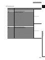
Remote input signal direction: High-speed counter
Remote output signal direction: Master/local
module Master/local module
module High-speed counter module
Module
type
Device
Description
number
RX30
RX31
RX32
RX33
RX34
RX35
Use prohibited
CH1 Measured pulse value update flag reset
completed (Function input terminal)
CH1 Measured pulse value update flag
(Function input terminal)
CH1 Measured pulse value update flag reset
completed (Latch counter input terminal)
CH1 Measured pulse value update flag
(Latch counter input terminal)
CH1 ON width setting change completed
(PWM output)
Device
Description
number
RY30
RY31
RY32
RY33
RY34
RY35
CH1 Pulse measurement start command
(Function input terminal)
CH1 Measured pulse value update flag reset
command (Function input terminal)
CH1 Pulse measurement start command
(Latch counter input terminal)
CH1 Measured pulse value update flag reset
command (Latch counter input terminal)
Use prohibited
CH1 ON width setting change request
(PWM output)
RX36
CH1 Error status
RY36
CH1 Error reset command
RX37
CH1 Warning status
RY37
Use prohibited
RX38
Use prohibited
RY38
CH2 Coincidence output enable command
RX39
CH2 Preset/replace completion
RY39
CH2 Preset/replace command
RX3A
Use prohibited
RY3A
CH2 Count down command
RX3B
CH2 External preset/replace (Z Phase) request
detection
RY3B
CH2 External preset/replace (Z Phase) request
detection reset command
Main
RX3C
Use prohibited
RY3C
CH2 Count enable command
module
RX3D
CH2 Counter function detection
RY3D
CH2 Selected counter function start command
RX3E
CH2 Cam switch execute/PWM output
RY3E
RX3F
CH2 Setting change completed
(Sampling counter/Periodic pulse counter)
RY3F
CH2 Update flag reset completed (Latch count
RX40
value/Sampling count value/Periodic pulse
RX42
RX43
RX44
RX45
40
CH2 Update flag (Latch count value/Sampling
count value/Periodic pulse count value)
CH2 Latch count value update flag reset
completed (Latch counter input terminal)
CH2 Latch count value update flag
(Latch counter input terminal)
CH2 Update flag reset completed (Measured
frequency value/Measured rotation speed value)
CH2 Update flag (Measured frequency
value/Measured rotation speed value)
output start command
CH2 Setting change request
(Sampling counter/Periodic pulse counter)
CH2 Update flag reset command (Latch count
RY40
count value)
RX41
CH2 Cam switch execute command/PWM
value/Sampling count value/Periodic pulse
count value)
RY41
RY42
RY43
RY44
Use prohibited
CH2 Latch count value update flag reset
command (Latch counter input terminal)
Use prohibited
CH2 Update flag reset command (Measured
frequency value/Measured rotation speed value)
RY45
Use prohibited
RX46
Use prohibited
RY46
Use prohibited
RX47
Use prohibited
RY47
Use prohibited
CHAPTER 3 SPECIFICATIONS
Remote input signal direction: High-speed counter
Remote output signal direction: Master/local
module Master/local module
module High-speed counter module
Module
type
Device
Description
number
RX48
RX49
RX4A
Main
module
RX4B
RX4C
RX4D
Use prohibited
CH2 Measured pulse value update flag reset
completed (Function input terminal)
CH2 Measured pulse value update flag
(Function input terminal)
CH2 Measured pulse value update flag reset
completed (Latch counter input terminal)
CH2 Measured pulse value update flag
(Latch counter input terminal)
CH2 ON width setting change completed
(PWM output)
Device
Description
number
RY48
RY49
RY4A
RY4B
RY4C
RY4D
CH2 Pulse measurement start command
(Function input terminal)
CH2 Measured pulse value update flag reset
command (Function input terminal)
3
CH2 Pulse measurement start command
(Latch counter input terminal)
CH2 Measured pulse value update flag reset
command (Latch counter input terminal)
Use prohibited
CH2 ON width setting change request
(PWM output)
RX4E
CH2 Error status
RY4E
CH2 Error reset command
RX4F
CH2 Warning status
RY4F
Use prohibited
Extension
RX50 to
Remote input (RX) of the connected extension
RY50 to
Remote output (RY) of the connected extension
module 1
RX5F
module is assigned.
RY5F
module is assigned.
Do not use any "Use prohibited" remote I/O signals. If any of the signals are used, correct operation of the module cannot be
guaranteed.
3.5 List of Remote I/O Signals
(1) Remote I/O signal of the extension module
The remote I/O signal differs depending on the model of the extension module.
• Extension I/O module
Refer to the following.
CC-Link IE Field Network Remote I/O Module User's Manual
41
3.6
List of Remote Register
This section lists remote registers for a master/local module.
In the example of the remote register assignment described in this section, the remote registers of the main module
are assigned to the remote registers of RWr0 to RWr3F and RWw0 to RWw3F.
The remote registers are assigned per station regardless of the main module or the extension module.
Remote register (RWr) is the information input from the high-speed counter module to the master/local module.
Remote register (RWw) is the information output from the master/local module to the high-speed counter module.
For details on the remote register, refer to the following.
Page 273, Appendix 2
Remote register (RWr) signal direction: High-speed
Remote register (RWw) signal direction: Master/local
counter module Master/local module
module High-speed counter module
Device
Description
number
Device
Description
number
RWr0
Counter value greater/smaller signal
RWw0
Point setting (Coincidence output 1)/
RWr1
EQU1 to EQU4 terminal status
RWw1
Lower limit value setting (Coincidence output 1)
RWr2
Cam switch output signal
RWw2
RWr3
Cam switch output terminal status
RWw3
RWr4
Use prohibited
RWw4
Point setting (Coincidence output 2)/
RWr5
Use prohibited
RWw5
Lower limit value setting (Coincidence output 2)
RWr6
Use prohibited
RWw6
RWr7
Use prohibited
RWw7
RWr8
Use prohibited
RWw8
Point setting (Coincidence output 3)/
RWr9
Use prohibited
RWw9
Lower limit value setting (Coincidence output 3)
RWrA
Use prohibited
RWwA
RWrB
Use prohibited
RWwB
RWrC
Use prohibited
RWwC
Point setting (Coincidence output 4)/
RWrD
Use prohibited
RWwD
Lower limit value setting (Coincidence output 4)
RWrE
Use prohibited
RWwE
RWrF
Use prohibited
RWwF
RWr10
RWr11
CH1 Present value
RWw10
RWw11
RWr12
CH1 Latch count value/Sampling count value/Periodic
RWw12
RWr13
pulse count, difference value
RWw13
RWr14
RWr15
CH1 Periodic pulse count, present value
RWr16
RWw14
RWw15
RWw16
CH1 Periodic pulse count value update check
RWr17
RWw17
RWr18
RWw18
CH1 Latch count value (Latch counter input terminal)
RWr19
RWw19
RWr1A
CH1 Measured frequency value/Measured rotation
RWw1A
RWr1B
speed value
RWw1B
42
Upper limit value setting (Coincidence output 1)
Upper limit value setting (Coincidence output 2)
Upper limit value setting (Coincidence output 3)
Upper limit value setting (Coincidence output 4)
CH1 Ring counter lower limit value
CH1 Ring counter upper limit value
CH1 Preset value setting
CH1 Time unit setting
(Sampling counter/Periodic pulse counter)
CH1 Cycle setting
(Sampling counter/Periodic pulse counter)
CH1 Time unit setting (Frequency
measurement/Rotation speed measurement)
CH1 Moving average count (Frequency
measurement/Rotation speed measurement)
CH1 Number of pulses per rotation
CHAPTER 3 SPECIFICATIONS
Remote register (RWr) signal direction: High-speed
Remote register (RWw) signal direction: Master/local
counter module Master/local module
module High-speed counter module
Device
Description
number
RWr1C
RWr1D
CH1 Measured pulse value (Function input terminal)
Device
Description
number
RWw1C
Use prohibited
RWw1D
CH1 PWM output assignment setting
RWr1E
CH1 Measured pulse value (Latch counter input
RWw1E
RWr1F
terminal)
RWw1F
RWr20
CH1 Status
RWw20
RWr21
CH1 External input status
RWw21
RWr22
CH1 Latest error code
RWw22
Use prohibited
RWr23
CH1 Latest warning code
RWw23
Use prohibited
RWr24
Use prohibited
RWw24
Use prohibited
RWr25
Use prohibited
RWw25
Use prohibited
RWr26
Use prohibited
RWw26
Use prohibited
RWr27
Use prohibited
RWw27
Use prohibited
RWr28
RWr29
CH2 Present value
RWw28
RWw29
RWr2A
CH2 Latch count value/Sampling count value/
RWw2A
RWr2B
Periodic pulse count, difference value
RWw2B
RWr2C
RWr2D
CH2 Periodic pulse count, present value
RWr2E
RWw2C
RWw2D
RWw2E
CH2 Periodic pulse count value update check
RWr2F
RWw2F
RWw30
CH2 Latch count value (Latch counter input terminal)
RWr31
RWw31
RWr32
CH2 Measured frequency value/
RWw32
RWr33
Measured rotation speed value
RWw33
RWr34
RWr35
CH2 Measured pulse value (Function input terminal)
CH1 Cycle setting (PWM output)
CH2 Ring counter lower limit value
CH2 Ring counter upper limit value
CH2 Preset value setting
CH2 Time unit setting
(Sampling counter/Periodic pulse counter)
CH2 Cycle setting
(Sampling counter/Periodic pulse counter)
CH2 Time unit setting (Frequency
measurement/Rotation speed measurement)
CH2 Moving average count (Frequency
measurement/Rotation speed measurement)
CH2 Number of pulses per rotation
RWw34
Use prohibited
RWw35
CH2 PWM output assignment setting
RWr36
CH2 Measured pulse value
RWw36
RWr37
(Latch counter input terminal)
RWw37
RWr38
CH2 Status
RWw38
RWr39
CH2 External input status
RWw39
RWr3A
CH2 Latest error code
RWw3A
Use prohibited
RWr3B
CH2 Latest warning code
RWw3B
Use prohibited
RWr3C
Use prohibited
RWw3C
Use prohibited
RWr3D
Use prohibited
RWw3D
Use prohibited
RWr3E
Use prohibited
RWw3E
Use prohibited
RWr3F*1
Use prohibited
RWw3F*1
Use prohibited
*1
3
3.6 List of Remote Register
RWr30
CH1 ON width setting (PWM output)
CH2 ON width setting (PWM output)
CH2 Cycle setting (PWM output)
RWr3F and RWw3F are used for the system in the synchronous communication mode.
43
Do not read or write the data to/from any "Use prohibited" remote registers. If the data is read or written from/to any of the
registers, correct operation of the module cannot be guaranteed.
The remote register information is not stored in the nonvolatile memory of the high-speed counter module. Thus, the remote
register information is initialized by turning off then on the power supply of the high-speed counter module.
44
CHAPTER 3 SPECIFICATIONS
3.7
List of Remote Buffer Memory
This section lists remote buffer memory areas of the high-speed counter module.
The remote buffer memory areas of the main module and extension module are assigned as shown below.
3
Main module
Extension module 1
Ex. Example of the remote buffer memory in the manual
Coincidence output comparison condition setting (address: 0102H)
Address of a high-speed counter module
Setting item
For details on the remote buffer memory, refer to the following.
• Details of Remote Buffer Memory Addresses (
Page 285, Appendix 3)
For details on the remote buffer memory of the connected extension module, refer to the following.
•
User's manual for the connected extension module
: Available ×: Unavailable
Decimal
Access method
Area
Hexadecimal
Description
CC IE Field
configuration
of GX Works2
0 to 255
0000H to 00FFH
256 to 511
0100H to 01FFH
512 to 767
0200H to 02FFH
768 to 1279
0300H to 04FFH
1280 to 1535
0500H to 05FFH
1536 to 1791
0600H to 06FFH
1792 to 2047
0700H to 07FFH
2048 to 2559
0800H to 09FFH
2560 to 4095
0A00H to 0FFFH
4096 to 4351
1000H to 10FFH
4352 to 4607
1100H to 11FFH
4608 to 4863
1200H to 12FFH
4864 to 5375
1300H to 14FFH
5376 to 8191
1500H to 1FFFH
REMFR
instruction,
REMTO
instruction*1
Station-based parameter data
Parameter area
Main module
Module-based
parameter data
*2
Extension module 1
System area
System area
Monitoring area
Main module
Module-based
monitoring data
Extension module 1
×
System area
Error history area
Station-based error history data
*2
Station-based control data
Module control data
area
System area
Module-based
control data
Extension module 1
×
System area
Extended
parameter area
Cam switch function parameter data
×
45
3.7 List of Remote Buffer Memory
Buffer memory address
*1
For the REMFR and REMTO instructions, refer to the following.
*2
User's manual for the master/local module used
For the access method, refer to the following.
• Parameter area (
• Error history area (
Page 84, Section 7.1)
Page 221, Section 11.1)
Do not access the system area using the REMFR or REMTO instruction. Doing so may cause the module to malfunction.
(1) Parameter area (address: 0000H to 04FFH)
For the parameter area, parameters can be set using the CC IE Field configuration of GX Works2 or using the
REMTO instruction.
The parameter in the parameter area is backed up to the nonvolatile memory.
The parameter backed up to the nonvolatile memory is read to the parameter area when the module power
supply is turned off then on or the module returns from remote reset.
If the parameter is written from the parameter setting of the CC IE Field configuration of GX Works2, it is also
written to the nonvolatile memory at that time. When the parameter is written using the REMTO instruction, it is
written to the nonvolatile memory when Initial data setting request flag (RY9) is turned off then on. At this time,
the parameter is written to the nonvolatile memory even though it is incorrect. When the power supply is turned
off then on with an incorrect parameter written, the incorrect parameter is read from the nonvolatile memory and
an error code is stored to CH Latest error code (RWr22, RWr3A). Take corrective action according to the error
code list. (
Page 224, Section 11.2)
Address
Type
Decimal
Description
Hexadecimal
0
0000H
Mode switch setting
1
0001H
2
Default*1
Read/
Write*2
9
R/W
Input response time setting
0005H
R/W
0002H
Output HOLD/CLEAR setting
0000H
R/W
3
0003H
Cyclic data update watch time setting
0
R/W
4 to 255
0004H to 00FFH
System area
256
0100H
Comparison output setting
0
R/W
257
0101H
Coincidence output channel assignment setting
0000H
R/W
258
0102H
Coincidence output comparison condition setting
0000H
R/W
259
0103H
Preset/replace setting at coincidence output
0000H
R/W
260
0104H
Cam switch output unit assignment setting
0
R/W
261
0105H
Cam switch output channel assignment setting
0000H
R/W
Module-based
262 to 287
0106H to 011FH
System area
parameter data
288
0120H
CH1 Operation mode setting
0
R/W
289
0121H
CH1 Count source selection
0
R/W
290
0122H
CH1 Pulse input mode
0
R/W
291
0123H
CH1 Counting speed setting
0
R/W
292
0124H
CH1 Counter format
0
R/W
293
0125H
CH1 Phase Z setting
0000H
R/W
294
0126H
CH1 Counter function selection
0
R/W
295
0127H
CH1 Function input logic setting
0
R/W
Station-based
parameter data
(main module)
46
CHAPTER 3 SPECIFICATIONS
Address
Type
Decimal
Module-based
parameter data
(main module)
Description
Hexadecimal
296
0128H
CH1 Latch counter input logic setting
297
0129H
CH1 External control input response time setting
298
012AH
299
012BH
300 to 319
012CH to 013FH
320
0140H
321
0141H
322
0142H
323
0143H
324
0144H
325
Default*1
Read/
Write*2
0
R/W
002AH
R/W
0
R/W
0
R/W
System area
CH2 Operation mode setting
0
R/W
CH2 Count source selection
0
R/W
CH2 Pulse input mode
0
R/W
CH2 Counting speed setting
0
R/W
CH2 Counter format
0
R/W
0145H
CH2 Phase Z setting
0000H
R/W
326
0146H
CH2 Counter function selection
0
R/W
327
0147H
CH2 Function input logic setting
0
R/W
328
0148H
CH2 Latch counter input logic setting
0
R/W
329
0149H
CH2 External control input response time setting
002AH
R/W
330
014AH
0
R/W
331
014BH
0
R/W
332 to 511
014CH to 01FFH
512 to 767
0200H to 02FFH
768 to 1279
0300H to 04FFH
CH1 Pulse measurement setting (Function input
terminal)
CH1 Pulse measurement setting (Latch counter
input terminal)
CH2 Pulse measurement setting (Function input
terminal)
CH2 Pulse measurement setting (Latch counter
input terminal)
System area
parameter data
(extension
The remote buffer memory of the connected
extension module is assigned.
3.7 List of Remote Buffer Memory
Module-based
module 1)
System area
*1
This is the value at default or initialization by Parameter area initialization command (address: 1002H).
*2
This shows whether read or write from programs is possible.
R: Readable
W: Writable
3
To activate the parameter data, turn off then on Initial data setting request flag (RY9). Writing the parameter data to the
parameter area does not activate the parameter data.
47
(a) Parameter area of the extension module
The remote buffer memory differs depending on the model of the extension module.
• Extension input module (NZ2EX2B1-16D)
Address
Decimal
Description
Hexadecimal
512
0200H
Extension module identification code
513 to 767
0201H to 02FFH
System area
Default*1
Read/
Write*2
0000H
R/W
*1
This is the value at default or initialization by Parameter area initialization command (address: 1002H).
*2
This shows whether read or write from programs is possible.
R: Readable
W: Writable
• Extension output module (NZ2EX2B1-16T, NZ2EX2B1-16TE)
Address
Decimal
48
Description
Hexadecimal
512
0200H
Extension module identification code
513
0201H
System area
514
0202H
Number of ON times integration function enable
515 to 767
0203H to 02FFH
System area
Default*1
Read/
Write*2
0000H
R/W
0000H
R/W
*1
This is the value at default or initialization by Parameter area initialization command (address: 1002H).
*2
This shows whether read or write from programs is possible.
R: Readable
W: Writable
CHAPTER 3 SPECIFICATIONS
(2) Monitoring area (address: 0500H to 09FFH)
Address
Type
Decimal
Station-based
monitoring data
Module-based
monitoring data
(main module)
Name
Hexadecimal
Default*1
Read/
Write*2
0000H
R
System area
CH1 Operation mode
0
R
CH1 Selected counter function
0
R
System area
CH2 Operation mode
0
R
CH2 Selected counter function
0
R
System area
1280 to 1535
0500H to 05FFH
System area
1536
0600H
Channel assignment (Coincidence output 1 to 4)
1537 to 1567
0601H to 061FH
1568
0620H
1569
0621H
1570 to 1599
0622H to 063FH
1600
0640H
1601
0641H
1602 to 1791
0642H to 06FFH
1792 to 2047
0700H to 07FFH
2048 to 2559
0800H to 09FFH
3
Module-based
monitoring data
(extension
The remote buffer memory of the connected
extension module is assigned.
module 1)
*1
*2
System area
This is the value for when the module power supply is turned off then on or at the remote reset.
This shows whether read or write from programs is possible.
R: Readable
W: Writable
3.7 List of Remote Buffer Memory
49
(a) Monitoring area of the extension module
The remote buffer memory differs depending on the model of the extension module.
• Extension input module (NZ2EX2B1-16D)
Address
Decimal
Hexadecimal
1792
0700H
Extension module identification code
1793 to 2047
0701H to 07FFH
System area
*1
*2
Default*1
Description
Read/
Write*2
0000H
R
This is the value for when the module power supply is turned off then on or at the remote reset.
This shows whether read or write from programs is possible.
R: Readable
W: Writable
• Extension output module (NZ2EX2B1-16T, NZ2EX2B1-16TE)
Address
Decimal
Default*1
Description
Hexadecimal
1792
0700H
Extension module identification code
1793 to 1807
0701H to 070FH
System area
1808 to 1809
0710H to 0711H
1810 to 1811
Read/
Write*2
0000H
R
Y0
0
R
0712H to 0713H
Y1
0
R
1812 to 1813
0714H to 0715H
Y2
0
R
1814 to 1815
0716H to 0717H
Y3
0
R
1816 to 1817
0718H to 0719H
Y4
0
R
1818 to 1819
071AH to 071BH
Y5
0
R
1820 to 1821
071CH to 071DH
Y6
0
R
1822 to 1823
071EH to 071FH
Number of ON times integration
Y7
0
R
1824 to 1825
0720H to 0721H
value
Y8
0
R
1826 to 1827
0722H to 0723H
Y9
0
R
1828 to 1829
0724H to 0725H
YA
0
R
1830 to 1831
0726H to 0727H
YB
0
R
1832 to 1833
0728H to 0729H
YC
0
R
1834 to 1835
072AH to 072BH
YD
0
R
1836 to 1837
072CH to 072DH
YE
0
R
1838 to 1839
072EH to 072FH
YF
0
R
1840 to 2047
0730H to 07FFH
*1
*2
System area
This is the value for when the module power supply is turned off then on or at the remote reset.
This shows whether read or write from programs is possible.
R: Readable
W: Writable
Number of ON times integration value Y0 to Number of ON times integration value YF are written to a nonvolatile memory in
the specified cycle.
50
CHAPTER 3 SPECIFICATIONS
(3) Error history area (address: 0A00H to 0FFFH)
Address
Type
Decimal
Description
Hexadecimal
Default*1
Read/
Write*2
2560
0A00H
Error code
0000H
R
2561
0A01H
Order of generation
0000H
R
0000H
R
[Error time] Month/Day
0000H
R
R
[Error time] First two digits of the
0A02H
2563
0A03H
2564
0A04H
[Error time] Hour/Minute
0000H
2565
0A05H
[Error time] Second/00H (Fixed)
0000H
R
2566
0A06H
Error code details 1
0000H
R
2567
0A07H
Error code details 2
0000H
R
2568
0A08H
Error code details 3
0000H
R
2569
0A09H
Error code details 4
0000H
R
2570
0A0AH
Error code details 5
0000H
R
2571
0A0BH
Error code details 6
0000H
R
2572
0A0CH
Error code details 7
0000H
R
2573
0A0DH
Error code details 8
0000H
R
2574
0A0EH
Error code details 9
0000H
R
2575
0A0FH
Error code details 10
0000H
R
2576 to 2591
0A10H to 0A1FH
Error history 2
Same as Error history 1.
2592 to 2607
0A20H to 0A2FH
Error history 3
Same as Error history 1.
2608 to 2623
0A30H to 0A3FH
Error history 4
Same as Error history 1.
2624 to 2639
0A40H to 0A4FH
Error history 5
Same as Error history 1.
2640 to 2655
0A50H to 0A5FH
Error history 6
Same as Error history 1.
2656 to 2671
0A60H to 0A6FH
Error history 7
Same as Error history 1.
Station-
2672 to 2687
0A70H to 0A7FH
Error history 8
Same as Error history 1.
based error
2688 to 2703
0A80H to 0A8FH
Error history 9
Same as Error history 1.
history data
2704 to 2719
0A90H to 0A9FH
Error history 10
Same as Error history 1.
2720 to 2735
0AA0H to 0AAFH
Error history 11
Same as Error history 1.
2736 to 2751
0AB0H to 0ABFH
Error history 12
Same as Error history 1.
2752 to 2767
0AC0H to 0ACFH
Error history 13
Same as Error history 1.
2768 to 2783
0AD0H to 0ADFH
Error history 14
Same as Error history 1.
2784 to 2799
0AE0H to 0AEFH
Error history 15
Same as Error history 1.
2800 to 4095
0AF0H to 0FFFH
System area
Stationbased error
history data
year/Last two digits of the year
Error history 1
*1
This is the value at default or initialization by Error history clear command (address: 1000H).
*2
This shows whether read or write from programs is possible.
R: Readable
W: Writable
3.7 List of Remote Buffer Memory
2562
3
The error history area is written to a nonvolatile memory when an error occurs.
51
(4) Module control data area (address: 1000H to 14FFH)
Address
Type
Decimal
Station-based
control data
Description
Hexadecimal
Default*1
Read/
Write*2
4096
1000H
Error history clear command
0000H
R/W
4097
1001H
Error history clear completed
0000H
R
4098
1002H
Parameter area initialization command
0000H
R/W
4099
1003H
Parameter area initialization completed
0000H
R
4100
1004H
Module operation information initialization command
0000H
R/W
4101
1005H
0000H
R
4102 to 4351
1006H to 10FFH
System area
4352 to 4607
1100H to 11FFH
System area
4608 to 4863
1200H to 12FFH
4864 to 5375
1300H to 14FFH
Module operation information initialization
completed
Module-based
control data
(main module)
Module-based
control data
(extension
The remote buffer memory of the connected
extension module is assigned.
module 1)
*1
*2
System area
This is the value for when the module power supply is turned off then on or at the remote reset.
This shows whether read or write from programs is possible.
R: Readable
W: Writable
(a) Module control data area of the extension module
The remote buffer memory differs depending on the model of the extension module.
• Extension input module (NZ2EX2B1-16D)
Address
Decimal
Hexadecimal
4608 to 4863
1200H to 12FFH
*1
*2
Description
Default*1
System area
Read/
Write*2
This is the value for when the module power supply is turned off then on or at the remote reset.
This shows whether read or write from programs is possible.
R: Readable
W: Writable
• Extension output module (NZ2EX2B1-16T, NZ2EX2B1-16TE)
Address
Decimal
1200H
4609
1201H
4610 to 4863
1202H to 12FFH
*1
*2
52
Default*1
Number of ON times integration value clear Y0 to YF
0000H
R/W
0000H
R
Hexadecimal
4608
Read/
Description
Number of ON times integration value clear
completed Y0 to YF
System area
This is the value for when the module power supply is turned off then on or at the remote reset.
This shows whether read or write from programs is possible.
R: Readable
W: Writable
Write*2
CHAPTER 3 SPECIFICATIONS
(5) Extended parameter area (address: 1500H to 1FFFH)
Type
Decimal
Description
Hexadecimal
5376
1500H
5377
1501H
5378 to 5379
1502H to 1503H
5380 to 5381
1504H to 1505H
5382 to 5383
1506H to 1507H
5384 to 5385
1508H to 1509H
5386 to 5387
150AH to 150BH
5388 to 5389
150CH to 150DH
5390 to 5391
150EH to 150FH
5392 to 5393
1510H to 1511H
5394 to 5395
1512H to 1513H
5396 to 5397
1514H to 1515H
5398 to 5399
1516H to 1517H
5400 to 5401
1518H to 1519H
5402 to 5403
151AH to 151BH
5404 to 5405
151CH to 151DH
5406 to 5407
151EH to 151FH
5408 to 5409
1520H to 1521H
5410 to 5503
1522H to 157FH
System area
5504 to 5537
1580H to 15A1H
Cam switch output 2
5538 to 5631
15A2H to 15FFH
System area
5632 to 5665
1600H to 1621H
Cam switch output 3
5666 to 5759
1622H to 167FH
System area
5760 to 5793
1680H to 16A1H
Cam switch output 4
5794 to 5887
16A2H to 16FFH
System area
5888 to 5921
1700H to 1721H
Cam switch output 5
5922 to 6015
1722H to 177FH
System area
parameter data
Default*1
Cam switch function, step type (Output 1)
Read/
Write*2
0
R/W
0
R/W
0
R/W
0
R/W
0
R/W
0
R/W
0
R/W
0
R/W
0
R/W
0
R/W
0
R/W
0
R/W
0
R/W
0
R/W
0
R/W
0
R/W
0
R/W
0
R/W
Cam switch function, number of steps
(Output 1)
Cam switch function, step No.1 setting
(Output 1)
Cam switch function, step No.2 setting
(Output 1)
Cam switch function, step No.3 setting
(Output 1)
Cam switch function, step No.4 setting
(Output 1)
Cam switch function, step No.5 setting
(Output 1)
Cam switch function, step No.6 setting
(Output 1)
Cam switch function, step No.7 setting
(Output 1)
Cam switch function, step No.8 setting
(Output 1)
Cam switch function, step No.9 setting
(Output 1)
Cam switch function, step No.10 setting
(Output 1)
Cam switch function, step No.11 setting
(Output 1)
Cam switch function, step No.12 setting
(Output 1)
Cam switch function, step No.13 setting
(Output 1)
Cam switch function, step No.14 setting
(Output 1)
Cam switch function, step No.15 setting
(Output 1)
Cam switch function, step No.16 setting
(Output 1)
Same as Cam switch output 1.
Same as Cam switch output 1.
Same as Cam switch output 1.
Same as Cam switch output 1.
53
3
3.7 List of Remote Buffer Memory
Cam switch function
Address
Address
Type
Decimal
Description
Hexadecimal
6016 to 6049
1780H to 17A1H
Cam switch output 6
6050 to 6143
17A2H to 17FFH
System area
6144 to 6177
1800H to 1821H
Cam switch output 7
6178 to 6271
1822H to 187FH
System area
6272 to 6305
1880H to 18A1H
Cam switch output 8
6306 to 6399
18A2H to 18FFH
System area
6400 to 6433
1900H to 1921H
Cam switch output 9
6434 to 6527
1922H to 197FH
System area
6528 to 6561
1980H to 19A1H
Cam switch output 10
6562 to 6655
19A2H to 19FFH
System area
Cam switch function
6656 to 6689
1A00H to 1A21H
Cam switch output 11
parameter data
6690 to 6783
1A22H to 1A7FH
System area
6784 to 6817
1A80H to 1AA1H
Cam switch output 12
6818 to 6911
1AA2H to 1AFFH
System area
6912 to 6945
1B00H to 1B21H
Cam switch output 13
6946 to 7039
1B22H to 1B7FH
System area
7040 to 7073
1B80H to 1BA1H
Cam switch output 14
7074 to 7167
1BA2H to 1BFFH
System area
7168 to 7201
1C00H to 1C21H
Cam switch output 15
7202 to 7295
1C22H to 1C7FH
System area
7296 to 7329
1C80H to 1CA1H
Cam switch output 16
7330 to 8191
1CA2H to 1FFFH
System area
Default*1
Read/
Write*2
Same as Cam switch output 1.
Same as Cam switch output 1.
Same as Cam switch output 1.
Same as Cam switch output 1.
Same as Cam switch output 1.
Same as Cam switch output 1.
Same as Cam switch output 1.
Same as Cam switch output 1.
Same as Cam switch output 1.
Same as Cam switch output 1.
Same as Cam switch output 1.
*1
This is the value at default or initialization by Parameter area initialization command (address: 1002H).
*2
This shows whether read or write from programs is possible.
R: Readable
W: Writable
The extended parameter data is written to a nonvolatile memory at the rising edge (off to on) of Initial data setting request
flag (RY9) or when the parameters are set on the parameter setting window. However, the extended parameters cannot be
set on the parameter setting window. Set the extended parameters from the program before setting parameters on the
parameter setting window.
The activation timing of the extended parameter data differs depending on the data type. Refer to the pages where details of
each data are described.
54
CHAPTER 4 THE PROCEDURE BEFORE OPERATION
CHAPTER 4
THE PROCEDURE BEFORE
OPERATION
This section describes the procedure before operation.
Check box
Setting a station number
Page 59, Section 6.1
4
Set the station number for a high-speed counter module.
Connection
When using an extension module, connect the extension module to
the high-speed counter module.
Mount the high-speed counter module to a DIN rail.
Page 60, Section 6.2,
Page 62, Section 6.3
Wiring
Page 67, Section 6.4,
*1
Connect the high-speed counter module to a power supply,
Ethernet cables, and external devices.
Page 69, Section 6.5,
Parameter settings and programming
Page 84, Section 7.1
Set parameters and create a program.
Page 92, Section 7.2.1*1
Page 72, Section 6.6
To replace the module, refer to this section.
To replace the module, follow the procedure described below.
• Stop the operation of the system and remove the high-speed counter module.
• Prepare a new high-speed counter module and perform the procedure above from "Setting a station number" to
"Parameter settings and programming". (The network parameter of the master station does not need to be set
again.)
• After checking the operation, restart the control.
55
Memo
56
CHAPTER 5 SYSTEM CONFIGURATION
CHAPTER 5
SYSTEM CONFIGURATION
This chapter describes system configuration using a high-speed counter module.
For CC-Link IE Field Network configuration, refer to the following.
User's manual for the master/local module used
5.1
High-Speed Counter Module System Configuration
The following shows system configuration using a high-speed counter module.
High-speed counter module
5
Extension module
5.1 High-Speed Counter Module System Configuration
57
5.2
Applicable Systems
(1) Applicable master station
When using a high-speed counter module, use the following products as a master station.
Model
QJ71GF11-T2
First five digits of serial number
"14102" or later
LJ71GF11-T2
QD77GF16
"14111" or later
When a master station other than the above is used, the high-speed counter module cannot be used.
(2) Connectable modules
One extension module can be connected to one high-speed counter module.
Module
Model
NZ2EX2B1-16D
Extension I/O module
NZ2EX2B1-16T
NZ2EX2B1-16TE
(3) Ethernet cable
For the specifications of the Ethernet cable, refer to the following.
User's manual for the master/local module used
(4) Software package
GX Works2 is required for setting and diagnosing the high-speed counter module. Install GX Works2 with the
following version.
High-speed counter module
NZ2GFCF-D62PD2
Extension I/O module
NZ2EX2B1-16D
NZ2EX2B1-16T
NZ2EX2B1-16TE
58
Software version
Version 1.98C or later
Software version
Version 1.91V or later
Version 1.98C or later
CHAPTER 6 INSTALLATION AND WIRING
CHAPTER 6
INSTALLATION AND WIRING
This chapter describes the installation and wiring of the high-speed counter module.
6.1
Station Number Setting
(1) Setting procedure
Set the station number with the rotary switch on the front of the module. The setting value of the station number
becomes valid when the module is powered on. Thus, set the station number when the module is powered off.
• The hundreds and tens places of the station number are set with x10.
• The ones place of the station number is set with x1.
Ex. To set the station number to 115, set the switch as shown below.
6
(2) Setting range
Set the station number from 1 to 120. Setting the value other than 1 to 120 causes a communication error and the
D LINK LED flashes.
● Do not set a station number duplicated with other station numbers. If the station number is duplicated, a communication
error occurs and the D LINK LED does not turn on.
59
6.1 Station Number Setting
● Changing the station number setting switch while the module is powered on causes a minor error and flashes the ERR.
LED.
Returning the station number setting switch to the previous setting eliminates the error after five seconds and turns off the
ERR. LED.
6.2
Installation Environment and Installation Position
6.2.1
Installation environment
(1) Installation location
Do not install the high-speed counter module to the place where:
• Ambient temperature is outside the range of 0 to 55°C;
• Ambient humidity is outside the range of 5 to 95% RH;
• Condensation occurs due to rapid temperature change;
• Corrosive gas or combustible gas is present;
• Conductive powder such as dust and iron powder, oil mist, salinity, or organic solvent is filled;
• The high-speed counter module is exposed to direct sunlight;
• A strong electric field or strong magnetic field is generated; and
• The high-speed counter module is subject to vibration and shock.
(2) Installation surface
Install the high-speed counter module on the flat surface. When the installation surface is uneven, excessive
force is applied to the printed-circuit board and may cause a defect.
6.2.2
Installation position
When installing the high-speed counter module in a control panel, provide clearance of 60mm or longer between the
module and the sides of the control panel or neighboring modules to ensure good ventilation and an easy module
change.
60mm
or longer
60mm
or longer
60mm
or longer
60mm
or longer
60
60mm
or longer
60mm
or longer
60mm
or longer
CHAPTER 6 INSTALLATION AND WIRING
6.2.3
Installation direction
The high-speed counter module can be installed in six directions. Use the DIN rail to install the module.
Downward installation
6
DIN rail
Horizontal installation
Vertical installation
Horizontal installation (upside down)
6.2 Installation Environment and Installation Position
6.2.3 Installation direction
Upward installation
61
6.3
Installation
6.3.1
Connecting extension modules
(1) Connecting procedure
1.
Remove the cover on the side of the module.
Do not dispose the removed cover, but store it.
2.
Release the module joint levers (two points) on the
side of the extension module. Slide the levers
vertically.
Release
3.
Insert the connector of the extension module into
that of the high-speed counter module so that they
are securely engaged.
Lock
4.
Lock the module joint levers (two points) on the
side of the extension module. Slide the levers
toward the module.
Check that the modules are securely connected.
Lock
62
CHAPTER 6 INSTALLATION AND WIRING
(2) Disconnecting procedure
Disconnect the modules by reversing the procedure above.
● Shut off the external power supply for the system in all phases before connecting or disconnecting extension modules.
● Lock the module joint levers securely. Failure to do so may cause malfunction, failure, or drop of the module.
6
6.3 Installation
6.3.1 Connecting extension modules
63
6.3.2
Mounting the modules on a DIN rail
An example of the use of the DIN rail stopper is described in the following procedure. Fix the module according to the
manual of the DIN rail stopper used.
(1) Mounting procedure
1.
Pull down all DIN rail hooks on the back of the
modules.
The hook should be pulled down until it clicks.
2.
Hang the upper tabs of the modules on a DIN rail,
and push the modules in position.
3.
Lock the DIN rail hooks to the DIN rail to secure the
modules in position.
Push each hook up until it clicks. If the hooks are
beyond the reach, use a tool such as a screwdriver.
4.
Loosen the screw on DIN rail stopper.
5.
Hitch the bottom hook of the DIN rail stopper to the
Hook
Hook
bottom of the DIN rail.
Hitch the hook according to the orientation of the arrow
on the front of the stopper.
Hitch the hook to
the bottom of the DIN rail.
64
CHAPTER 6 INSTALLATION AND WIRING
6.
Hitch the hook to
the top of the DIN rail.
top of the DIN rail.
7.
DIN rail
stopper
Hitch the upper hook of the DIN rail stopper to the
Slide the DIN rail stopper up to the left side of the
modules.
8.
DIN rail
stopper
Hold the DIN rail stopper in the direction opposite to
the arrow on the stopper and tighten the screw with
6
a screwdriver.
DIN rail
stopper
9.
Install the DIN rail stopper on the right side of the
module in the same procedure.
Install the stopper upside down for the right side.
● Tighten the DIN rail mounting screws at intervals of 200mm or less.
65
6.3 Installation
6.3.2 Mounting the modules on a DIN rail
● Do not slide modules from the edge of the DIN rail when mounting them. Doing so may damage the metal part located on
the back of the module.
(2) Removal procedure
Remove the modules from the DIN rail by reversing the procedure above.
(3) Applicable DIN rail model (compliant with IEC 60715)
• TH35-7.5Fe
• TH35-7.5Al
(4) Interval between DIN rail mounting screws
Tighten the screws at intervals of 200mm or less.
(5) DIN rail stopper
Use a stopper that is attachable to the DIN rail.
66
CHAPTER 6 INSTALLATION AND WIRING
6.4
Wiring with Terminal Block for Module Power Supply
and FG
(1) Tightening torque
Tighten the terminal block screws within the following specified torque range.
Tightening the screws too much may damage the module case.
Screw type
Tightening torque range
Terminal block mounting screw (M2.5 screw)
0.2 to 0.3N•m
Terminal screw (M2.5 screw)
0.5 to 0.6N•m
(2) Wire to be used
The following table describes the wire to be connected to the terminal block for module power supply and FG.
Diameter
Type
Material
Temperature rating
20 to 16 AWG
Stranded
Copper
75°C or more
6
For applicable solderless terminals, refer to the following.
Performance Specifications (
Page 29, Section 3.2)
(3) Installing and removing the terminal block
To remove the terminal block, loosen the terminal block mounting screw with a slotted screwdriver.
To install the terminal block, tighten the terminal block mounting screw.
Failure to secure the terminal block may cause drop, short circuit, malfunction.
6.4 Wiring with Terminal Block for Module Power Supply and FG
67
(4) Connecting and disconnecting the cable
To connect the cable, insert the wire with the terminal screw loosened and tighten the screw. To disconnect the
cable, pull out the wire with the terminal screw loosened with a slotted screwdriver.
(5) Processing method of the cable terminal
Strip the cable about 10mm from the top.
To use a bar solderless terminal, connect it to the stripped part.
ble
Ca
Ar
o
d
un
10
m
m
(6) List of bar solderless terminals
The following table lists recommended bar solderless terminals.
Product name
Bar solderless terminal
Tool dedicated for bar solderless terminal
Bar solderless terminal
Tool dedicated for bar solderless terminal
68
Model name
Applicable wire size
TE 0.5-10
0.5mm2
TE 0.75-10
0.75mm2
TE 1.0-10
0.9 to 1.0mm2
TE 1.5-10
1.25 to 1.5mm2
Nichifu Co., Ltd.
NH79
AI 0.5-10WH
0.5mm2
AI 0.75-10GY
0.75mm2
AI 1-10RD
1.0mm2
AI 1.5-10BK
1.5mm2
CRIMPFOX6
Contact
Phoenix Contact Co., Ltd.
CHAPTER 6 INSTALLATION AND WIRING
6.5
Wiring of Ethernet Cable
(1) Connecting the Ethernet cable
(a) Connecting
1.
Power off the power supplies of the high-speed
counter module and the external device.
2.
Push the Ethernet cable connector into the highspeed counter module until it clicks. Pay attention
to the connector's direction.
6
3.
4.
5.
Power on the module.
Power on the external device.
Check that the LINK LED on the port into which the
may take a few seconds to turn on after power-on. If
the LINK LED does not turn on, refer to the
troubleshooting section and take a corrective
action. (
Page 241, Section 11.3)
69
6.5 Wiring of Ethernet Cable
Ethernet cable is connected is on. The LINK LED
● PORT1 and PORT2 need not to be distinguished. When only one connector is used in star topology, either PORT1 or
PORT2 can be connected.
Either one can be used.
● When two connectors are used in line topology or ring topology, an Ethernet cable can be connected to the connectors in
any combination. For example, the cable can be connected between PORT1s and between PORT1 and PORT2.
Connection between
PORT1s or PORT2s
Connection between
PORT1 and PORT2
(b) Disconnecting
1.
2.
70
Power off the high-speed counter module.
Press the latch down and unplug the Ethernet cable.
CHAPTER 6 INSTALLATION AND WIRING
(2) Precautions
(a) Laying Ethernet cables
• Place the Ethernet cable in a duct or clamp them. If not, dangling cable may swing or inadvertently be
pulled, resulting in damage to the module or cables or malfunction due to poor contact.
• Do not touch the core of the connector of the cable or the module, and protect it from dirt and dust. If any
oil from your hand, or any dirt or dust sticks to the core, it can increase transmission loss, causing data link
to fail.
• Check the following:
• The Ethernet cable is securely connected.
• The Ethernet cable is not shorted.
• The connectors are securely connected.
(b) Broken cable latch
Do not use Ethernet cables with broken latches. Doing so may cause the cable to unplug or malfunction.
6
(c) Connecting and disconnecting the Ethernet cable
Hold the connector part when connecting and disconnecting the Ethernet cable. Pulling the cable connected to
the module may result in damage to the module or cable or malfunction due to poor contact.
(d) Connectors without the Ethernet cable
To prevent dust from entering the module, attach the provided connector cover.
(e) Maximum station-to-station distance (Maximum Ethernet cable length)
The maximum station-to-station distance is 100m. However, the distance may be shorter depending on the
operating environment of the cable. For details, contact the manufacturer of the cables used.
6.5 Wiring of Ethernet Cable
(f) Bending radius of the Ethernet cable
There are restrictions on the bending radius of the Ethernet cable. Check the bending radius in the
specifications of the Ethernet cables used.
71
6.6
Wiring of Connectors for External Devices
This section describes how to wire the high-speed counter module with an encoder or a controller.
6.6.1
Wiring precautions
To obtain the maximum performance from the functions of the high-speed counter module and improve the system
reliability, an external wiring with high durability against noise is required.
Precautions for the external wiring are as follows.
(1) Wiring
• Terminals are prepared depending on the voltage of the signal to be input. Connecting to a terminal with a
different voltage may cause malfunction of the module and failure of the connected devices.
• In 1-phase input, always connect a pulse input cable to the A-phase side.
(2) Connectors for external devices
• Securely connect the connectors for external devices (A6CON1/A6CON2/A6CON4) to the high-speed
counter module connectors and securely tighten the two screws.
• When disconnecting the cable from the high-speed counter module, do not pull the cable by the cable part.
Hold the connector part of the cable. Pulling the cable connected to the module may result in malfunction or
damage to the module or cable.
(3) DC power supply
• Each DC power supply to be connected to the high-speed counter module, encoder, and controller must be
connected to a different power supply.
72
CHAPTER 6 INSTALLATION AND WIRING
(4) Measures against noise
• The high-speed counter module may incorrectly count the pulses when pulse-state noises are input.
• When inputting high-speed pulses, take the following measures against noise.
Measure 1
Use shielded twisted pair cables, and ground them on the encoder side with a ground
resistance of 100 or less.
Measure 2
Use the shortest possible shielded twisted pair cables, placing them not parallel with
noise-generating power cables or I/O cables and at a distance of 150mm or more.
• The following figure shows an example of a noise reduction measure.
High-speed
counter module
Ground shielded twisted pair cables on the encoder side.
Use the shortest possible shielded cables.
Inverter
Terminal
block
High-speed counter module
Terminal
block
Install a cable at least
150mm away from
the I/O cable of a high
voltage equipment such
as a relay or inverter.
(Pay attention to wiring
in the control panel as
well.)
AC
motor
6
Avoid using a solenoid valve or inductive load together with the cable in a metallic pipe.
If a sufficient distance from the power line cannot be ensured due to duct wiring,
use shielded cables such as CVVS for the power line.
Keep a shortest distance between the encoder and relay box.
Relay box If the distance from the high-speed counter module to the encoder is long,
Cart
Encoder
• Ground the shielded twisted pair cable on the encoder side (relay box). (Wiring example: with a sink type
encoder (24V))
+24V
Current for encoder
To A
To B
To the high-speed
counter module
To the encoder
0V
A
B
24V
E
E
Connect the shielded cable of the encoder to the shielded cable
of the shielded twisted pair cable in the relay box. If the shielded
cable of the encoder is not grounded in the encoder, ground it to
the relay box as shown by the dotted lines.
73
6.6 Wiring of Connectors for External Devices
6.6.1 Wiring precautions
a voltage drop may occur. Using a measuring instrument such as
a synchroscope on the terminal block of the relay box, check that the voltages
in the encoder operation and stop status are within the rated voltage range.
If a voltage drop is too large, increase the cable size or use a 24VDC
encoder that will consume less current.
6.6.2
Connectors for external devices
The connectors and crimp tools for use with the high-speed counter module must be purchased separately by the
user.
The following tables list the connector types and the crimp tool.
(1) Precautions
• Tighten the connector screws within the following specified torque range.
Screw type
Tightening torque range
Connector screw (M2.6 screw)
0.20 to 0.29N•m
• Use copper wires having temperature rating of 75°C or more for the connectors.
• When required, use UL-approved connectors.
(2) Connector types*1
Type
Model
Applicable wire size
0.088 to 0.3mm2 (28 to 22 AWG)
Soldering type
(stranded)
A6CON1
(straight out)
When using 40 wires, use those having
an outer diameter of 1.3mm or smaller.
Crimp type
0.088 to 0.24mm2
A6CON2
(straight out)
(28 to 24 AWG) (stranded)
0.088 to 0.3mm2 (28 to 22 AWG)
Soldering type
(stranded)
A6CON4
(straight out/diagonal out)
When using 40 wires, use those having
an outer diameter of 1.3mm or smaller.
*1
The A6CON3 (pressure-displacement type, straight out) connector cannot be used for the high-speed counter module.
(3) Connector crimp tool
Type
Crimp tool
74
Model
FCN-363T-T005/H
Applicable wire size
0.088 to 0.24mm
(28 to 24 AWG)
2
Contact
FUJITSU COMPONENT LIMITED
http://www.fcl.fujitsu.com/en/
CHAPTER 6 INSTALLATION AND WIRING
6.6.3
I/O interfaces with external devices
This section describes the high-speed counter module interfaces to connect with external devices.
(1) Terminal layouts and pin numbers of connectors for external devices
The following figure and table show the terminal layouts and the pin numbers of the high-speed counter module
connector for external devices.
B20
B19
B18
B17
B16
B15
B14
B13
B12
B11
B10
B09
B08
B07
B06
B05
B04
B03
B02
B01
Pin number
Symbol
A20
A19
A18
A17
A16
A15
A14
A13
A12
A11
A10
A09
A08
A07
A06
A05
A04
A03
A02
A01
Pin number
6
Symbol
A1-24V
A20
A1-5V
B19
A1-DIF
A19
A1-COM
B18
B1-24V
A18
B1-5V
B17
B1-DIF
A17
B1-COM
B16
Z1-24V
A16
Z1-5V
B15
Z1-DIF
A15
Z1-COM
B14
A2-24V
A14
A2-5V
B13
A2-DIF
A13
A2-COM
B12
B2-24V
A12
B2-5V
B11
B2-DIF
A11
B2-COM
B10
Z2-24V
A10
Z2-5V
B09
Z2-DIF
A09
Z2-COM
B08
FUNC1-24V
A08
LATCH1-24V
B07
FUNC1-5V
A07
LATCH1-5V
B06
CTRLCOM
A06
CTRLCOM
B05
FUNC2-24V
A05
LATCH2-24V
B04
FUNC2-5V
A04
LATCH2-5V
B03
EQU1
A03
EQU2
B02
EQUCOM
A02
EQUCOM
B01
EQU3
A01
EQU4
6.6 Wiring of Connectors for External Devices
6.6.3 I/O interfaces with external devices
B20
75
(2) List of I/O signal details
The following table lists the signals for the high-speed counter module connectors for external devices.
I/O
classification
Input
Output
76
Symbol
Pin
number
Signal name
A1-24V
B20
CH1 Phase A pulse input 24V (+)
A1-5V
A20
CH1 Phase A pulse input 5V (+)
A1-DIF
B19
CH1 Phase A pulse differential input (+)
A1-COM
A19
CH1 Phase A pulse input common (-)
B1-24V
B18
CH1 Phase B pulse input 24V (+)
B1-5V
A18
CH1 Phase B pulse input 5V (+)
B1-DIF
B17
CH1 Phase B pulse differential input (+)
Description
• This signal inputs + (plus) side of phase A pulse.
• This signal inputs - (minus) side of phase A pulse.
• This signal inputs + (plus) side of phase B pulse.
B1-COM
A17
CH1 Phase B pulse input common (-)
• This signal inputs - (minus) side of phase B pulse.
Z1-24V
B16
CH1 Phase Z input 24V (+)
Z1-5V
A16
CH1 Phase Z input 5V (+)
Z1-DIF
B15
CH1 Phase Z differential input (+)
• This signal inputs + (plus) side of phase Z.
• Turn on this signal to replace a count value by the external signal.
• The count value is replaced with the preset value when this signal
becomes on (when "CH1 Z phase (Preset) trigger setting" is set
to "0: Rising").
Z1-COM
A15
CH1 Phase Z input common (-)
A2-24V
B14
CH2 Phase A pulse input 24V (+)
A2-5V
A14
CH2 Phase A pulse input 5V (+)
A2-DIF
B13
CH2 Phase A pulse differential input (+)
A2-COM
A13
CH2 Phase A pulse input common (-)
B2-24V
B12
CH2 Phase B pulse input 24V (+)
B2-5V
A12
CH2 Phase B pulse input 5V (+)
B2-DIF
B11
CH2 Phase B pulse differential input (+)
• This signal inputs - (minus) side of phase Z.
• This signal inputs + (plus) side of phase A pulse.
• This signal inputs - (minus) side of phase A pulse.
• This signal inputs + (plus) side of phase B pulse.
B2-COM
A11
CH2 Phase B pulse input common (-)
• This signal inputs - (minus) side of phase B pulse.
Z2-24V
B10
CH2 Phase Z input 24V (+)
Z2-5V
A10
CH2 Phase Z input 5V (+)
Z2-DIF
B09
CH2 Phase Z differential input (+)
• This signal inputs + (plus) side of phase Z.
• Turn on this signal to replace a count value by the external signal.
• The count value is replaced with the preset value when this signal
becomes on (when "CH2 Z phase (Preset) trigger setting" is set
to "0: Rising").
Z2-COM
A09
CH2 Phase Z input common (-)
FUNC1-24V
B08
CH1 Function input 24V
FUNC1-5V
B07
CH1 Function input 5V
FUNC2-24V
B05
CH2 Function input 24V
FUNC2-5V
B04
CH2 Function input 5V
LATCH1-24V
A08
CH1 Latch counter input 24V
LATCH1-5V
A07
CH1 Latch counter input 5V
LATCH2-24V
A05
CH2 Latch counter input 24V
LATCH2-5V
A04
CH2 Latch counter input 5V
CTRLCOM
A06, B06
Control input common
EQU1
B03
Coincidence output 1 (+)
EQU2
A03
Coincidence output 2 (+)
EQU3
B01
Coincidence output 3 (+)
EQU4
A01
Coincidence output 4 (+)
EQUCOM
A02, B02
Coincidence output common (-)
• This signal inputs - (minus) side of phase Z.
• Turn on this signal to execute the selected counter function start
command by the external signal.
• Turn on this signal to latch a count value by the external signal.
• The count value is latched and stored in remote registers when
this signal becomes on.
• Common for function input
• Common for latch counter input
• It is common between channels.
• With the coincidence output function activated, the high-speed
counter module outputs a signal when the count value is matched
with the preset comparison condition.
• When the PWM output function is used, the high-speed counter
module outputs the PWM waveform.
• It inputs 0V when Coincidence output 1 to 4 are used.
• Common for coincidence outputs
• It is common between channels.
CHAPTER 6 INSTALLATION AND WIRING
(3) Interface with external devices
The following table lists the high-speed counter module interfaces to connect with external devices.
I/O
classification
Pin
number
Internal circuit
240
820
240
820
270
270
4.1k
4.1k
Input
390
470
390
470
270
2.32k
2.32k
4.1k
Operation
Input
voltage
(guaranteed
value)
Operating
current
(guaranteed
value)
Response
time
AM26C31 or
equivalent
CH1
CH2
B19
B13
Phase A pulse
differential input (+)
A20
A14
Phase A pulse
input 5V (+)
When ON
4.5 to 5.5V
4 to 8mA
When OFF
2V or lower
1.0mA or lower
B20
B14
Phase A pulse
input 24V (+)
When ON
21.6 to 26.4V
4 to 6mA
When OFF
5V or lower
1.0mA or lower
A19
A13
Phase A pulse
input common (-)
B17
B11
Phase B pulse
differential input (+)
AM26C31 or
equivalent
A18
A12
Phase B pulse
input 5V (+)
B18
B12
Phase B pulse
input 24V (+)
A17
A11
Phase B pulse
input common (-)
B15
B09
Phase Z differential
input (+)
When OFF
A16
A10
Phase Z input 5V
(+)
When ON
4.5 to 5.5V
4 to 8mA
When OFF
2V or lower
1.0mA or lower
2.5µs or less
When ON
21.6 to 26.4V
4 to 6mA
1.25µs or less
When OFF
5V or lower
1.0mA or lower
2.5µs or less
B10
Phase Z input 24V
(+)
A15
A09
Phase Z input
common (-)
B07
B04
Function input 5V
B08
B05
Function input 24V
B06,
A06
B06,
A06
Control input
common
A07
A04
Latch counter input
5V
B16
A08
A05
Latch counter input
24V
When ON
4.5 to 5.5V
4 to 8mA
When OFF
2V or lower
1.0mA or lower
When ON
21.6 to 26.4V
4 to 6mA
When OFF
5V or lower
1.0mA or lower
When ON
AM26C31 or
equivalent
6
1.25µs or less
When ON
4.5 to 5.5V
7 to 12mA
20µs or less
When OFF
2V or lower
1.0mA or lower
100µs or less
When ON
21.6 to 26.4V
7 to 12mA
20µs or less
When OFF
5V or lower
1.0mA or lower
100µs or less
When ON
4.5 to 5.5V
7 to 12mA
20µs or less
When OFF
2V or lower
1.0mA or lower
100µs or less
When ON
21.6 to 26.4V
7 to 12mA
20µs or less
When OFF
5V or lower
1.0mA or lower
100µs or less
77
6.6 Wiring of Connectors for External Devices
6.6.3 I/O interfaces with external devices
240
820
Signal name
I/O
classification
Pin
number
Internal circuit
Signal name
CH1
CH2
B03
Coincidence output
1 (+)
A03
Coincidence output
2 (+)
Operation
Input
voltage
(guaranteed
value)
Operating
current
(guaranteed
value)
Response
time
EQU1
IO 5V
680
4.7k
EQU2
680
4.7k
EQU3
Output
B01
Coincidence output
3 (+)
A01
Coincidence output
4 (+)
B02,
A02
B02,
A02
Coincidence output
common (-)
680
4.7k
EQU4
•
•
•
•
Operating load voltage: 4.75 to 30VDC
Maximum load current: 0.1A/point
Maximum voltage drop at ON: 0.5V
Response time
OFF ON: 1µs or less
(rated load, resistive load)
ON OFF: 1µs or less
(rated load, resistive load)
680
EQUCOM
4.7k
*1
For EQU1 to EQU4, the assignment to CH1 or CH2 can be changed.
(4) ON/OFF status of input signals
The ON/OFF status of input signals depends on external wiring and the logic setting.
The following table shows an example of CH Function input terminal (FUNC1, FUNC2).
The ON/OFF status for other input signals is the same as CH Function input terminal (FUNC1, FUNC2).
Logic status*1
External
ON/OFF status of CH Function input terminal (FUNC1, FUNC2) in
wiring
terms of the high-speed counter module
No voltage
Positive logic
applied
Voltage applied
No voltage
Negative logic
applied
Voltage applied
*1
ON
ON
OFF
Configure the logic setting by CH Function input logic setting (address: 0127H, 0147H). For details on the setting, refer
to the following.
Page 285, Appendix 3
78
OFF
CHAPTER 6 INSTALLATION AND WIRING
6.6.4
Encoders that can be connected
This section lists the encoders that can be connected to the high-speed counter module.
• Open collector output type encoders
• CMOS level voltage output type encoders
• Line driver output type encoders (AM26LS31 or equivalent)
● Verify that the encoder output voltage meets the specifications of the high-speed counter module.
● TTL level voltage output type encoders cannot be used with the high-speed counter module.
6
6.6 Wiring of Connectors for External Devices
6.6.4 Encoders that can be connected
79
6.7
Wiring Example (Between a High-Speed Counter Module
and an Encoder)
(1) Example of wiring with an open collector output type encoder (24VDC)
High-speed counter module
DIF
B19(B13)
Phase A
5V
A20(A14)
24V
B20(B14)
240
270
4.1k
820
COM
A19(A13)
Encoder
Shielded twisted pair cable
DIF
B17(B11)
Phase B
24V
OUT
5V
A18(A12)
24V
B18(B12)
240
270
24V
OUT
4.1k
820
COM
A17(A11)
24V
OUT
B15(B09)
E
DIF
Phase Z
5V
A16(A10)
24V
B16(B10)
240
270
External
power
supply
4.1k
820
COM
24VDC
0V
A15(A09)
When wiring the high-speed counter module and an encoder, separate power cables and signal cables. The following figure
shows examples.
● Example of correct wiring
High-speed COM
counter module
Pulse input
OUT
24V
Shielded twisted pair cable
+24V
0V
Encoder
E
External
power
supply
24VDC
0V
● Example of incorrect wiring
High-speed
COM
counter module
Pulse input
OUT
24V
Shielded twisted pair cable
+24V
0V
E
External
power
supply
80
24VDC
0V
Encoder
Because a current flows through
the shielded twisted pair cables
in the same direction,
canceling effect does not work
and pulses become susceptible
to electromagnetic induction.
CHAPTER 6 INSTALLATION AND WIRING
(2) Example of wiring with a voltage output type encoder (5VDC)
High-speed counter module
DIF
Phase A
B19(B13)
5V
A20(A14)
24V
B20(B14)
240
270
4.1k
820
COM
A19(A13)
Encoder
Shielded twisted pair cable
DIF
Phase B
B17(B11)
OUT
GND
5V
A18(A12)
24V
B18(B12)
240
270
OUT
GND
4.1k
820
COM
DIF
Phase Z
5V
6
OUT
GND
A17(A11)
B15(B09)
A16(A10)
E
24V
B16(B10)
240
270
4.1k
820
COM
External
power
supply
5VDC
0V
A15(A09)
6.7 Wiring Example (Between a High-Speed Counter Module and an Encoder)
(3) Example of wiring with a line driver (equivalent to AM26LS31) encoder
High-speed counter module
DIF
Phase A
B19(B13)
5V
A20(A14)
24V
B20(B14)
240
270
4.1k
820
Encoder
COM
A19(A13)
Shielded twisted pair cable
DIF
Phase B
5V
B17(B11)
A
A
A18(A12)
24V
B18(B12)
240
270
B
4.1k
B
820
COM
Z
A17(A11)
Z
DIF
Phase Z
5V
B15(B09)
E
A16(A10)
24V
B16(B10)
240
270
4.1k
820
COM
A15(A09)
81
6.8
Wiring Example (Between a Controller and External
Input Terminals)
(1) Example of wiring with a sink type controller
High-speed counter module
Controller
5V
B07(B04)
24V
B08(B05)
390
Function
Shielded twisted pair cable
24V
2.32k
OUT
470
CTRLCOM
B06(A06)
Shield
E
5V
A07(A04)
390
Latch counter
2.32k
24V
A08(A05)
Shielded twisted pair cable
24V
OUT
470
Shield
E
External
power
supply
24VDC
0V
(2) Example of wiring with a source type controller
Controller
High-speed counter module
5V
B07(B04)
24V
B08(B05)
390
Function
Shielded twisted pair cable
OUT
2.32k
GND
470
CTRLCOM
B06(A06)
E
5V
A07(A04)
24V
A08(A05)
390
Latch counter
Shielded twisted pair cable
OUT
2.32k
GND
470
E
External
power
supply
82
24VDC
0V
CHAPTER 6 INSTALLATION AND WIRING
6.9
Wiring Example (with Coincidence Output Terminals)
(1) Example of wiring with coincidence output terminals (sink output type)
High-speed counter module
EQU1
Digital isolator
B03
Coincidence
output 1
Load
680
EQU2
4.7k
Load
A03
Coincidence
output 2
680
EQU3
4.7k
Load
B01
Coincidence
output 3
6
680
EQU4
4.7k
Load
A01
Coincidence
output 4
680
4.7k
EQUCOM
A02(B02)
6.9 Wiring Example (with Coincidence Output Terminals)
External
power
supply
10.8 to
26.4VDC
0V
83
CHAPTER 7
VARIOUS SETTINGS
This chapter describes the setting procedures of the high-speed counter module.
7.1
Parameter Setting
Set the parameter of this module with the network parameter written to the CPU module of the master station. For the
setting procedure of the master station, refer to the following.
User's manual for the master/local module used
Remark
● Check "Set the network configuration settings in CC IE Field configuration window" on the "MELSECNET/CC IE/Ethernet
Module Configuration" window in advance.
● To select an extension module in the "CC IE Field Configuration" window, select the following models from the "Module
List" window.
Extension module type
Name
Input module
NZ2EX-16(DI)
Output module
NZ2EX-16(DO)
● When points less than the ones of the high-speed counter module and extension module are set for the remote I/O signal
and remote register, no error occurs. The cyclic transmission is performed for the data of the points set from the start.
84
CHAPTER 7 VARIOUS SETTINGS
(1) Precautions
(a) Before parameter settings
• Read and write the parameter settings of this module with the CPU module in the STOP status. Reading
and writing are unavailable in the RUN status.
• Check that the start I/O number of the network parameter of the master station matches that of the PLC
parameter. If they differ, the parameter settings cannot be read or written.
(b) Parameter settings
• When using the high-speed counter module, enable the block data assurance per station. When it is
disabled, correct operation of the high-speed counter module cannot be guaranteed.
Do not uncheck the box.
7
For the block data assurance per station, refer to the following.
User's manual for the master/local module used
high-speed counter module cannot be guaranteed because the module operates with the block data
assurance per station disabled when the CCPASET instruction is executed.
• When using the extension module, write the module parameter (
Page 86, Section 7.1 (2)). If the
parameter of the extension module has not been written, the error code (1F30H) is stored in CH1 Latest
error code (RWr22), Error flag (RXA) turns on, and the ERR. LED turns on.
85
7.1 Parameter Setting
• Do not set the parameter using the CCPASET instruction in the master station. Correct operation of the
(2) Setting procedure
1.
Display the "CC IE Field Configuration" window.
• When the master/local module is the QJ71GF11-T2
Project window
[Parameter]
[Network Parameter]
[Ethernet/CC IE/MELSECNET]
button
• When the master/local module is the LJ71GF11-T2
Project window
[Parameter]
[Network Parameter]
[Ethernet/CC IE Field]
button
2.
Select the high-speed counter module in "List of stations" on the "CC IE Field Configuration"
window.
List of stations
3.
Open the "Parameter Processing of Slave Station" window.
[CC IE Field Configuration]
4.
86
[Online]
Set "Parameter write" for "Method selection".
[Parameter Processing of Slave Station]
CHAPTER 7 VARIOUS SETTINGS
5.
Double-click the item to change the setting, and input the setting value.
• Items to input from the pull-down list
Double-click the item to set to display the pull-down list. Select the item.
• Items to input from the text box
Double-click the item to set, and input the setting value.
The box cannot be unchecked.
Text box type
The list cannot be folded.
Pull-down list type
7
Mode switch setting
Setting details
0: Normal mode (Asynchronous communication mode)
9: Automatical judgment mode
7.1 Parameter Setting
Setting item
Reference
Page 102, Section 8.2
3: 2ms
4: 5ms
Input response time setting
5: 10ms
Page 189, Section 8.23 (3)
6: 20ms
7: 70ms
Output HOLD/CLEAR setting
Cyclic data update watch time setting
Comparison output setting
0: CLEAR
1: HOLD
• 0 (Not monitor)
• 1 to 20 (0.1 to 2 seconds, in increments of 100ms)
Page 182, Section 8.20
Page 183, Section 8.21
0: Coincidence Output Function
1: Cam Switch Function
Coincidence output 1
0: CH1
channel assignment setting
1: CH2
Coincidence output 2
0: CH1
channel assignment setting
1: CH2
Coincidence output 3
0: CH1
channel assignment setting
1: CH2
Coincidence output 4
0: CH1
channel assignment setting
1: CH2
Page 114, Section 8.5
87
Setting item
Coincidence output 1 comparison
condition setting
Coincidence output 2 comparison
condition setting
Coincidence output 3 comparison
condition setting
Coincidence output 4 comparison
condition setting
Setting details
0: Coincidence Output
1: Within-range Output
2: Out-of-range Output
0: Coincidence Output
1: Within-range Output
2: Out-of-range Output
0: Coincidence Output
Page 114, Section 8.5
1: Within-range Output
2: Out-of-range Output
0: Coincidence Output
1: Within-range Output
2: Out-of-range Output
Preset/replace setting at coincidence
0: Present value not replaced
output (Coincidence output 1)
1: Present value replaced
Preset/replace setting at coincidence
0: Present value not replaced
output (Coincidence output 2)
1: Present value replaced
Cam switch output unit assignment
0: No Assignment
setting
1: Stage 1
Cam switch output 1 channel assignment
0: CH1
setting
1: CH2
Cam switch output 2 channel assignment
0: CH1
setting
1: CH2
Cam switch output 3 channel assignment
0: CH1
setting
1: CH2
Cam switch output 4 channel assignment
0: CH1
setting
1: CH2
Cam switch output 5 channel assignment
0: CH1
setting
1: CH2
Cam switch output 6 channel assignment
0: CH1
setting
1: CH2
Cam switch output 7 channel assignment
0: CH1
setting
1: CH2
Cam switch output 8 channel assignment
0: CH1
setting
1: CH2
Cam switch output 9 channel assignment
0: CH1
setting
1: CH2
Cam switch output 10 channel
0: CH1
assignment setting
1: CH2
Cam switch output 11 channel
0: CH1
assignment setting
1: CH2
Cam switch output 12 channel
0: CH1
assignment setting
1: CH2
Cam switch output 13 channel
0: CH1
assignment setting
1: CH2
Cam switch output 14 channel
0: CH1
assignment setting
1: CH2
88
Reference
Page 126, Section 8.5.3
Page 129, Section 8.5.4
CHAPTER 7 VARIOUS SETTINGS
Setting item
Setting details
Cam switch output 15 channel
0: CH1
assignment setting
1: CH2
Cam switch output 16 channel
0: CH1
assignment setting
1: CH2
Reference
Page 129, Section 8.5.4
0: Normal Mode
1: Frequency Measurement Mode
Operation mode setting
2: Rotation Speed Measurement Mode
Page 99, Section 7.3
3: Pulse Measurement Mode
4: PWM Output Mode
0: A Phase/B Phase
Count source selection
1: Coincidence Output 1
Page 288, Appendix 3 (6)
2: Coincidence Output 2
0: 1-Phase Multiple of 1
1: 1-Phase Multiple of 2
Pulse input mode
2: CW/CCW
3: 2-Phase Multiple of 1
Page 104, Section 8.3.1
4: 2-Phase Multiple of 2
5: 2-Phase Multiple of 4
7
0: 10kpps
1: 100kpps
2: 200kpps
Counting speed setting
3: 500kpps
4: 1Mpps
Page 29, Section 3.2
5: 2Mpps
7: 8Mpps
Counter format
0: Linear Counter
1: Ring Counter
Page 107, Section 8.4
0: Rising
Z phase (Preset) trigger setting
1: Falling
2: Rising + Falling
Page 136, Section 8.6 (2)
3: During ON
External preset/replace (Z Phase) request
0: ON at detection
detection setting
1: Not ON at detection
Counter function selection
Function input logic setting
Latch counter input logic setting
Page 136, Section 8.6 (2)
0: Count Disable Function
Page 143, Section 8.9
1: Latch Counter Function
Page 145, Section 8.10
2: Sampling Counter Function
Page 148, Section 8.11
3: Periodic Pulse Counter Function
Page 151, Section 8.12
4: Count disable/Preset/replace Function
Page 154, Section 8.13
5: Latch counter/Preset/replace Function
Page 157, Section 8.14
0: Positive Logic
1: Negative Logic
0: Positive Logic
1: Negative Logic
Page 291, Appendix 3 (9)
Page 291, Appendix 3 (9)
89
7.1 Parameter Setting
6: 4Mpps
Setting item
Setting details
Setting
Z phase input response time setting
time
0.25µs
2.5µs
1
0.1ms
0.1ms
2
1.0ms
1.0ms
OFF ON Response
ON OFF Response
time
time
0
0.02ms
0.1ms
1
0.1ms
0.1ms
2
1.0ms
1.0ms
OFF ON Response
ON OFF Response
time
time
Setting
Latch counter input response time setting
ON OFF Response
time
0
Setting
Function input response time setting
OFF ON Response
0
0.02ms
0.1ms
1
0.1ms
0.1ms
2
1.0ms
1.0ms
Pulse measurement setting (Function
0: Pulse ON Width
input terminal)
1: Pulse OFF Width
Pulse measurement setting (Latch
0: Pulse ON Width
counter input terminal)
1: Pulse OFF Width
90
6.
Click the
7.
8.
Click the
button and the following window is displayed.
button.
The parameter is written to the high-speed counter module.
Reference
Page 292, Appendix 3 (10)
Page 292, Appendix 3 (10)
Page 292, Appendix 3 (10)
Page 171, Section 8.18
Page 171, Section 8.18
CHAPTER 7 VARIOUS SETTINGS
● When using the extension module, also set the parameter of the extension module.
For the parameter of the extension module, refer to the following.
Manual for the extension module used
● Set all the items for the parameter. If any blank exists, the parameter cannot be written to the high-speed counter module.
● To read the parameter from the high-speed counter module, set "Parameter read" for "Method selection" and click the
button.
● When the following message is displayed, take corrective action for the error code in <>. (
Page 224, Section 11.2)
● When the parameters are written, the contents in the extended parameter area are stored in the nonvolatile memory.
● When writing the parameters while Initial data processing request flag (RX8) is off, set values in the remote registers
(RWw) beforehand. The values in the remote registers (RWw) related to the setting values of the parameters are
checked at the writing. If the setting is incorrect, an error occurs.
7
7.1 Parameter Setting
91
7.2
Changing the Parameter
This section describes the procedures to change the parameter.
The precautions to take when changing the parameter are same as the following.
• Precautions (
7.2.1
Page 85, Section 7.1 (1))
Changing the network configuration
When changing the network configuration diverting the created project, set the parameter in the following procedure.
1.
2.
3.
4.
Power off the module.
Connect the modules again according to the desired network configuration.
Power on the module.
Display the "CC IE Field Configuration" window.
• When the master/local module is the QJ71GF11-T2
Project window
[Parameter]
[Network Parameter]
[Ethernet/CC IE/MELSECNET]
button
• When the master/local module is the LJ71GF11-T2
Project window
[Parameter]
[Network Parameter]
[Ethernet/CC IE Field]
button
5.
Drag and drop a module to set the slave station. Input a numerical value to set the station number
of the station. Change the value as necessary.
92
CHAPTER 7 VARIOUS SETTINGS
6.
Select the high-speed counter module in "List of stations" on the "CC IE Field Configuration"
window.
List of stations
7.
Open the "Parameter Processing of Slave Station" window.
[CC IE Field Configuration]
8.
[Online]
[Parameter Processing of Slave Station]
Set "Parameter read" for "Method selection".
7
9.
Click the
button and the following window is displayed.
7.2 Changing the Parameter
7.2.1 Changing the network configuration
10. Click the
button.
11. The parameter is read from the high-speed counter module.
12. Set "Parameter write" for "Method selection".
93
13. Set "Write Value". The following are the procedure.
• Click the title cell of "Read Value" to select all the items and copy them.
• Click the title cell of "Write Value" to select all the items and paste the copy.
• Select the items to be changed, and set new values.
14. Click the
button and the following window is displayed.
15. Click the
button.
16. The parameter is written to the high-speed counter module.
The module parameter setting of the slave station is now completed.
17. Close the "CC IE Field Configuration" window.
[CC IE Field Configuration]
18. Click the
[Close with Reflecting the Setting]
button to display the refresh parameter setting window.
19. Set the refresh parameter. Change the value as necessary.
94
CHAPTER 7 VARIOUS SETTINGS
20. Write the set parameter to the CPU module of the master station and reset the CPU module.
RESET
21. Change the status of the CPU module of the master station to RUN.
The network configuration setting is now completed.
RUN
7
7.2 Changing the Parameter
7.2.1 Changing the network configuration
95
7.2.2
Changing the parameter without changing the network
configuration
To change only the created module parameter of the slave station without changing the network configuration, set the
parameter in the following procedure.
1.
Display the "CC IE Field Configuration" window.
• When the master/local module is the QJ71GF11-T2
Project window
[Parameter]
[Network Parameter]
[Ethernet/CC IE/MELSECNET]
button
• When the master/local module is the LJ71GF11-T2
Project window
[Parameter]
[Network Parameter]
[Ethernet/CC IE Field]
button
2.
Select the high-speed counter module in "List of stations" on the "CC IE Field Configuration"
window.
List of stations
3.
Open the "Parameter Processing of Slave Station" window.
[CC IE Field Configuration]
96
[Online]
4.
Set "Parameter read" for "Method selection".
5.
Click the
[Parameter Processing of Slave Station]
button and the following window is displayed.
CHAPTER 7 VARIOUS SETTINGS
6.
7.
Click the
8.
Set "Parameter write" for "Method selection".
9.
Set "Write Value". The following are the procedure.
button.
The parameter is read from the high-speed counter module.
7
• Click the title cell of "Read Value" to select all the items and copy them.
• Click the title cell of "Write Value" to select all the items and paste the copy.
• Select the items to be changed, and set new values.
7.2 Changing the Parameter
7.2.2 Changing the parameter without changing the network configuration
97
10. Click the
button and the following window is displayed.
11. Click the
button.
12. The parameter is written to the high-speed counter module.
The module parameter setting of the slave station is completed.
98
CHAPTER 7 VARIOUS SETTINGS
7.3
Operation Mode List
This section lists the comparison output setting and counter function selection that can be combined with each
operation mode.
: Can be set/: Cannot be set/: Same as normal mode (asynchronous communication mode)
Drive mode
Normal mode
(asynchronous
Operation mode
setting
communication mode)
Setting
Function name
value
*1
Comparison
output setting
*2
Coincidence
Cam
Synchronous
Counter
communi-
function
cation
selection
mode
Reference
*3
This mode operates according to the
combination of each function and
setting.
Page 107,
Linear counter function
Section
7
8.4.1
Page 109,
Ring counter function
Section
8.4.2
Comparison output function
Page 114,
Page 115,
Coincidence output function
Section
8.5.2
Page 126,
Preset/replace (at coincidence
output) function
Normal mode
0
Section
8.5.3
Page 129,
Cam switch function
Section
8.5.4
Preset/replace function (using RY
command or phase Z input terminal)
Latch counter function by latch
counter input terminal
Count disable function
Latch counter function (counter
function selection)
Sampling counter function
Periodic pulse counter function
Count disable/preset/replace
function
Latch counter/preset/replace
function
0
1
2
3
4
5
Page 134,
Section 8.6
Page 139,
Section 8.7
Page 143,
Section 8.9
Page 145,
Section 8.10
Page 148,
Section 8.11
Page 151,
Section 8.12
Page 154,
Section 8.13
Page 157,
Section 8.14
99
7.3 Operation Mode List
Section 8.5
Drive mode
Normal mode
(asynchronous
Operation mode
setting
communication mode)
Setting
Function name
value
*1
Comparison
output setting
*2
Coincidence
Cam
Synchronous
Counter
communi-
function
cation
selection
mode
Reference
*3
In this mode, the pulses of the pulse
input terminals in phase A and B are
Frequency
measurem
1
Page 163,
counted and the frequency is
Section 8.16
automatically calculated.
ent mode
Frequency measurement function
In this mode, the pulses of the pulse
input terminals in phase A and B are
Rotation
speed
measurem
2
ent mode
counted and the rotation speed is
Page 167,
automatically calculated.
Section 8.17
Rotation speed measurement
Dedicated
function
mode
In this mode, the ON width or OFF
width of pulses input to the function
Pulse
measurem
3
Page 171,
input terminal or latch counter input
Section 8.18
terminal is measured.
ent mode
Pulse measurement function
In this mode, the PWM waveform of
200kHz at a maximum is output from
PWM
output
4
Page 175,
any coincidence output 1 to 4
Section 8.19
terminals (EQU1 to EQU4).
mode
PWM output function
Error notification function
Output HOLD/CLEAR setting
function
Cyclic data update watch function
Page 184,
Section 8.22
Page 182,
Section 8.20
Page 183,
Section 8.21
Function at the extension I/O module
installation
Common
Input function (extension input
module)
Output function (extension output
module)
Input response time setting function
(extension input module)
External power supply monitoring
function (extension output module)
Number of ON times integration
function (extension output module)
100
*1
The value set in CH Operation mode setting (address: 0120H, 0140H)
*2
The value set in Comparison output setting (address: 0100H)
*3
The value set in CH Counter function selection (address: 0126H, 0146H)
Page 187,
Section 8.23
CHAPTER 8 FUNCTIONS
CHAPTER 8
FUNCTIONS
This chapter describes the high-speed counter module functions.
8.1
Mode Shift at Power-on
At power-on, the mode of the high-speed counter module shifts to any of the following.
• Unit test mode
• Normal mode (asynchronous communication mode)
• Synchronous communication mode
The following table lists conditions where the mode shifts.
a)
b)
Power-on
Unit test mode
(Drive mode switch)
Normal mode
(asynchronous
communication mode)
Symbol
Mode
Synchronous
communication mode
8
Condition
a)
Unit test mode
mode shifts to the unit test mode.
For details, refer to the following.
Unit Test (
Page 244, Section 11.4)
If the station number setting switch is set to 1 to 120, the mode shifts according to the setting of Mode
switch setting (address: 0000H) and the type of the module that operates as the master station of the
b)
(Drive mode switch)
high-speed counter module.
For details, refer to the following.
Drive mode switch (
Page 102, Section 8.2)
101
8.1 Mode Shift at Power-on
If "X10" of the station number setting switch is set to "TEST" and "X1" of the switch is set to "0", the
8.2
Drive Mode Switch
The drive modes of the high-speed counter module are the normal mode (asynchronous communication mode) and
synchronous communication mode.
The following table lists the type and the operation of the mode.
Type
Operation
Normal mode (asynchronous
The present value is updated with reference to the internal control cycle of the high-speed counter
communication mode)
module.
Synchronous communication mode
The present value is updated in synchronization with the operation cycle of a simple motion
module.
The drive mode can be selected by setting Mode switch setting (address: 0000H). Note that the synchronous
communication mode can be used only when the following conditions are met. If the conditions are met, the highspeed counter module operates in the synchronous communication mode.
• Mode switch setting (address: 0000H) is set to Automatical judgment mode (9).
• The high-speed counter module is connected to the simple motion module with a serial number (first five
digits) of "15092" or later.
(1) Setting procedure
1.
Set "Parameter write" for "Method selection".
"CC IE Field Configuration" window
[CC IE Field Configuration]
2.
Select a high-speed counter module in "List of stations".
[Online]
[Parameter Processing of Slave Station]
Set "Mode switch setting" to "0: Normal mode (Asynchronous communication mode)", or "9:
Automatical judgment mode".
The following table lists the setting value of "Mode switch setting" and the drive mode.
Setting value of "Mode switch
Operation
setting"
0: Normal mode (Asynchronous
The high-speed counter module operates in the normal mode (asynchronous communication
communication mode)
mode).
"9: Automatical judgment mode"
*1
The drive mode is automatically set according to the type of the module that operates as the
master station of the high-speed counter module.*1
The drive mode varies depending on the module of the master station as shown below.
Master station
Drive mode (when "Mode switch setting" is set to "9: Automatical
judgment mode")
Master/local module
Simple motion module
(First five digits of the serial number are
Normal mode (asynchronous communication mode)
"15091" or earlier.)
Simple motion module
(First five digits of the serial number are
Synchronous communication mode
"15092" or later.)
3.
102
Click the
button to write the parameter to the high-speed counter module.
CHAPTER 8 FUNCTIONS
4.
Check that "0190H" is stored in CH1 Latest warning code (RWr23).
[Online]
5.
[Monitor]
[Device/Buffer Memory Batch]
The high-speed counter module starts operating in the set drive mode by turning off and on the
power or performing the remote reset.
To operate the high-speed counter module connected to a simple motion module in the normal mode (asynchronous
communication mode), set "Mode switch setting" to "0: Normal mode (Asynchronous communication mode)".
8
8.2 Drive Mode Switch
103
8.3
Pulse Input Modes and Counting Methods
8.3.1
Types of pulse input modes
There are six pulse input modes: 1-phase pulse input (1 multiple/2 multiples), CW/CCW pulse input, and 2-phase
pulse input (1 multiple/2 multiples/4 multiples).
(1) Pulse input modes and count timing
Pulse input
Count timing
mode
A
For counting up
B and CH
Count down command
(RY22, RY3A)
Counts on the rising edge () of A.
B and CH Count down command (RY22, RY3A)
are off.
1-phase multiple of 1
A
For counting
down
B or CH
Count down command
(RY22, RY3A)
A
For counting up
B and CH
Count down command
(RY22, RY3A)
Counts on the falling edge () of A.
B or CH Count down command (RY22, RY3A) is
on.
Counts on the rising edge () and the falling edge ()
of A.
B and CH Count down command (RY22, RY3A)
are off.
1-phase multiple of 2
A
For counting
down
For counting up
B or CH
Count down command
(RY22, RY3A)
A
Counts on the rising edge () and the falling edge ()
of A.
B or CH Count down command (RY22, RY3A) is
on.
Counts on the rising edge () of A.
B is off.
B
CW/CCW
For counting
A
A is off.
Counts on the rising edge () of B.
down
B
For counting up
A
Counts on the rising edge () of A while B is off.
B
2-phase multiple of 1
For counting
A
down
B
104
Counts on the falling edge () of A while B is off.
CHAPTER 8 FUNCTIONS
Pulse input
Count timing
mode
A
For counting up
Counts on the rising edge () of A while B is off.
Counts on the falling edge () of A while B is on.
B
2-phase multiple of 2
For counting
A
Counts on the rising edge () of A while B is on.
Counts on the falling edge () of A while B is off.
down
B
Counts on the rising edge () of A while B is off.
A
For counting up
Counts on the falling edge () of A while B is on.
Counts on the rising edge () of B while A is on.
B
2-phase multiple of 4
Counts on the falling edge () of B while A is off.
Counts on the rising edge () of A while B is on.
For counting
A
Counts on the falling edge () of A while B is off.
Counts on the rising edge () of B while A is off.
down
B
Counts on the falling edge () of B while A is on.
When using the phase B pulse input or CH Count down command (RY22, RY3A) for 1-phase pulse input, turn off the
unused signals.
When the phase B pulse input or CH Count down command (RY22, RY3A) is on, countdown is performed with the phase
A pulse input.
8
(a) 1-phase pulse input
For 1-phase pulse input, multiple of 1 or multiple of 2 can be selected as a counting method.
The following figure shows the relationship between phase A pulse input and phase B pulse input or CH
8.3 Pulse Input Modes and Counting Methods
8.3.1 Types of pulse input modes
Count down command (RY22, RY3A).
High-speed counter module
Encoder
Pulse input
A
B
B or CH Count down command
(RY22, RY3A)
105
(b) CW/CCW pulse input
For CW/CCW pulse input, pulses can be counted up with the phase A pulse input and counted down with the
phase B pulse input.
The following figure shows the relationship between phase A pulse input and phase B pulse input.
High-speed counter module
Encoder
Encoder
Addition pulse input
Subtraction pulse input
A
B
(c) 2-phase pulse input
For 2-phase pulse input, multiple of 1, multiple of 2, or multiple of 4 can be selected as a counting method.
The phase difference between phase A pulses and phase B pulses determines whether the pulses are counted
up or down.
The following figure shows the relationship between phase A pulse input and phase B pulse input.
High-speed counter module
Phase A pulse input
A
Encoder
Phase B pulse input
8.3.2
B
Counting method setting
Set the counting method in the CC IE Field configuration.
1.
Set "Parameter write" for "Method selection".
"CC IE Field Configuration" window
[CC IE Field Configuration]
2.
106
Set "CH Pulse input mode".
Select a high-speed counter module in "List of stations".
[Online]
[Parameter Processing of Slave Station]
CHAPTER 8 FUNCTIONS
8.4
Counter Format Selection
Set the counter format in the CC IE Field configuration.
1.
Set "Parameter write" for "Method selection".
"CC IE Field Configuration" window
[CC IE Field Configuration]
2.
Select a high-speed counter module in "List of stations".
[Online]
[Parameter Processing of Slave Station]
Set "CH Counter format".
8.4.1
Linear counter function
(1) Operation of the linear counter
• When the linear counter is selected, pulses are counted between -2147483648 (lower limit value) and
2147483647 (upper limit value).
• The preset/replace function and the comparison output function can be used together.
• The following figure shows the relationship between CH Present value (RWr10 to RWr11, RWr28 to
RWr29) of the counter and remote registers at overflow and underflow for the linear counter function.
8
Controlled by the high-speed counter module
Controlled by the program
8.4 Counter Format Selection
8.4.1 Linear counter function
3) Overflow
+2147483647
CH Present value
(RWr10 to RWr11,
RWr28 to RWr29)
0
-2147483648
1) Underflow
ON (1)
CH
CH
Underflow detection flag
(RWr20.b1, RWr38.b1)
OFF (0)
ON (1)
Overflow detection flag
(RWr20.b2, RWr38.b2)
OFF (0)
CH
Preset/replace command
(RY21, RY39)
ON
2)
4)
OFF
T1 or more*1
T1 or more*1
107
No.
Description
For counting down from the lower limit value (-2147483648) in CH Present value (RWr10 to RWr11, RWr28 to RWr29), the
1)
underflow error occurs and CH Underflow detection flag (RWr20.b1, RWr38.b1) is changed to Detected (1) from Not detected (0).
For details on the underflow error, refer to the following.
Page 108, Section 8.4.1 (2)
When CH Preset/replace command (RY21, RY39) is turned off then on to clear the underflow error, the value in CH Preset
2)
value setting (RWw14 to RWw15, RWw2C to RWw2D) is stored in CH Present value (RWr10 to RWr11, RWr28 to RWr29) and
CH Underflow detection flag (RWr20.b1, RWr38.b1) is changed to Not detected (0) from Detected (1) .
Counting in CH Present value (RWr10 to RWr11, RWr28 to RWr29) resumes.
For counting up from the upper limit value (2147483647) in CH Present value (RWr10 to RWr11, RWr28 to RWr29), the overflow
3)
error occurs and CH Overflow detection flag (RWr20.b2, RWr38.b2) is changed to Detected (1) from Not detected (0).
For details on the overflow error, refer to the following.
Page 108, Section 8.4.1 (2)
When CH Preset/replace command (RY21, RY39) is turned off then on to clear the overflow error, the value in CH Preset value
4)
setting (RWw14 to RWw15, RWw2C to RWw2D) is stored in CH Present value (RWr10 to RWr11, RWr28 to RWr29) and CH
Overflow detection flag (RWr20.b2, RWr38.b2) is changed to Not detected (0) from Detected (1).
Counting in CH Present value (RWr10 to RWr11, RWr28 to RWr29) resumes.
*1
For T1, refer to Page 302, Appendix 4.
(2) Overflow error and underflow error
• When "0: Linear Counter" is selected for "CH Counter format", the underflow error occurs at counting down
from -2147483648 (lower limit value) in CH Present value (RWr10 to RWr11, RWr28 to RWr29) and the
overflow error occurs at counting up from 2147483647 (upper limit value).
• If the overflow error occurs, CH Overflow detection flag (RWr20.b2, RWr38.b2) is set to Detected (1) and
CH Overflow/underflow error (error code: 200H) is stored in CH Latest error code (RWr22, RWr3A).
Then, the counting stops. The value in CH Present value (RWr10 to RWr11, RWr28 to RWr29) does not
change from 2147483647 even when pulses are input.
• If the underflow error occurs, CH Underflow detection flag (RWr20.b1, RWr38.b1) is set to Detected (1)
and CH Overflow/underflow error (error code: 200H) is stored in CH Latest error code (RWr22,
RWr3A). Then, the counting stops. The value in CH Present value (RWr10 to RWr11, RWr28 to RWr29)
does not change from -2147483648 even when pulses are input.
• An overflow and underflow error is cleared by the preset/replace function. After CH Overflow detection flag
(RWr20.b2, RWr38.b2) and CH Underflow detection flag (RWr20.b1, RWr38.b1) are set to Not detected
(0), the counting resumes. Though, CH Latest error code (RWr22, RWr3A) is held until it is reset. Reset
CH Latest error code (RWr22, RWr3A) by CH Error reset command (RY36, RY4E).
108
CHAPTER 8 FUNCTIONS
8.4.2
Ring counter function
(1) Operation of the ring counter
When "1: Ring Counter" is selected for "CH Counter format", pulses are counted repeatedly within the range
between CH Ring counter lower limit value (RWw10 to RWw11, RWw28 to RWw29) and CH Ring counter
upper limit value (RWw12 to RWw13, RWw2A to RWw2B) specified by the user.
The overflow and underflow errors do not occur under the ring counter function.
The preset/replace function and the comparison output function can be used together under the ring counter
function as well as under the linear counter function.
The following figure shows the relationship among CH Present value (RWr10 to RWr11, RWr28 to RWr29),
CH Ring counter lower limit value (RWw10 to RWw11, RWw28 to RWw29), and CH Ring counter upper limit
value (RWw12 to RWw13, RWw2A to RWw2B).
+2147483647
CH Ring counter
upper limit value
(RWw12 to RWw13,
RWw2A to RWw2B)
CH Present value
(RWr10 to RWr11,
RWr28 to RWr29)
2)
0
CH Ring counter
lower limit value
(RWw10 to RWw11,
RWw28 to RWw29)
8
1)
3)
-2147483648
Description
When CH Present value (RWr10 to RWr11, RWr28 to RWr29) is counted up from "CH Ring counter upper limit value (RWw12
1)
to RWw13, RWw2A to RWw2B) - 1", CH Ring counter lower limit value (RWw10 to RWw11, RWw28 to RWw29) is stored in CH
Present value (RWr10 to RWr11, RWr28 to RWr29).
2)
Count-up pulse input is changed to count-down pulse input.
3)
to RWw11, RWw28 to RWw29), "CH Ring counter upper limit value (RWw12 to RWw13, RWw2A to RWw2B) - 1" is stored in
When CH Present value (RWr10 to RWr11, RWr28 to RWr29) is counted down from CH Ring counter lower limit value (RWw10
CH Present value (RWr10 to RWr11, RWr28 to RWr29).
109
8.4 Counter Format Selection
8.4.2 Ring counter function
No.
(2) Counting range of the ring counter
One of the following three counting ranges of the ring counter is determined by the relationship among CH
Present value (RWr10 to RWr11, RWr28 to RWr29), CH Ring counter lower limit value (RWw10 to RWw11,
RWw28 to RWw29), and CH Ring counter upper limit value (RWw12 to RWw13, RWw2A to RWw2B) at the
time when CH Count enable command (RY24, RY3C) is turned on or when the preset/ replace function is
performed.
• Ring counter lower limit value Present value Ring counter upper limit value (This range is normally
used.)
• "Present value < Ring counter lower limit value" or "Ring counter upper limit value < Present value"
• Ring counter lower limit value = Ring counter upper limit value
Set the ring counter upper limit value and the ring counter lower limit value according to the condition "Ring
counter lower limit value Ring counter upper limit value". When CH Count enable command (RY24, RY3C) is
turned off then on with the condition not satisfied, CH Ring counter upper/lower limit value setting error (error
code: 210H) is stored in CH Latest error code (RWr22, RWr3A) and counting does not start. To start counting,
set the ring counter upper limit value and the ring counter lower limit value according to the condition "Ring
counter lower limit value Ring counter upper limit value" and turn off then on CH Count enable command
(RY24, RY3C). The OFF time must be longer than T1.
For T1, refer to Page 302, Appendix 4.
110
CHAPTER 8 FUNCTIONS
(a) Ring counter lower limit value Present value Ring counter upper limit value
• For counting up
When the value in CH Present value (RWr10 to RWr11, RWr28 to RWr29) reaches CH Ring counter
upper limit value (RWw12 to RWw13, RWw2A to RWw2B), the value in CH Ring counter lower limit
value (RWw10 to RWw11, RWw28 to RWw29) is automatically stored in CH Present value (RWr10 to
RWr11, RWr28 to RWr29).
• For counting down
When the value in CH Present value (RWr10 to RWr11, RWr28 to RWr29) reaches CH Ring counter
lower limit value (RWw10 to RWw11, RWw28 to RWw29), the value in CH Ring counter lower limit value
(RWw10 to RWw11, RWw28 to RWw29) is held as the present value. The value "ring counter upper limit
value - 1" is stored in CH Present value (RWr10 to RWr11, RWr28 to RWr29) at the next count-down
pulse input.
Both for counting up and down, the value in CH Ring counter upper limit value (RWw12 to RWw13, RWw2A
to RWw2B) is not stored in CH Present value (RWr10 to RWr11, RWr28 to RWr29). (Except for the case that
the present value equals to the ring counter upper limit value when CH Count enable command (RY24,
RY3C) is turned off then on, or when the preset/replace function is performed. When pulses are counted up or
down in the status, the operation is the same as that of when pulses are counted from CH Ring counter lower
limit value (RWw10 to RWw11, RWw28 to RWw29).)
For example, if CH Count enable command (RY24, RY3C) is turned on when CH Ring counter lower limit
value (RWw10 to RWw11, RWw28 to RWw29) is 0, CH Ring counter upper limit value (RWw12 to RWw13,
RWw2A to RWw2B) is 2000, and CH Present value (RWr10 to RWr11, RWr28 to RWr29) is 500, the counting
range and the CH Present value (RWr10 to RWr11, RWr28 to RWr29) change as follows.
CH Ring counter lower limit value
(RWw10 to RWw11, RWw28 to RWw29)
0
8
CH Present value CH Ring counter upper limit value
(RWr10 to RWr11, (RWw12 to RWw13, RWw2A to RWw2B)
RWr28 to RWr29)
2000
500
-2147483648
8.4 Counter Format Selection
8.4.2 Ring counter function
2147483647
Counting range
CH Present value
(RWr10 to RWr11,
RWr28 to RWr29)
500
501
CH Ring counter
upper limit value
(RWw12 to RWw13,
RWw2A to RWw2B)
to
1998
1999
(2000)
0
CH Ring counter
lower limit value
(RWw10 to RWw11,
RWw28 to RWw29)
1
2
to
498
499
In counting
up
The value of CH Ring counter upper limit value
(RWw12 to RWw13, RWw2A to RWw2B),
2000, is not stored in CH Present value
(RWr10 to RWr11, RWr28 to RWr29).
CH Present value
(RWr10 to RWr11,
RWr28 to RWr29)
500
499
CH Ring counter
upper limit value
(RWw12 to RWw13,
RWw2A to RWw2B)
to
2
1
(2000)
0
CH Ring counter
lower limit value
(RWw10 to RWw11,
RWw28 to RWw29)
1999
1998
to
502
501
In counting
down
The value of CH Ring counter lower limit value
(RWw10 to RWw11, RWw28 to RWw29),
0, is stored in CH Present value
(RWr10 to RWr11, RWr28 to RWr29).
111
(b) "Present value < Ring counter lower limit value" or "Ring counter upper limit value <
Present value"
• For counting up
When the value in CH Present value (RWr10 to RWr11, RWr28 to RWr29) reaches CH Ring counter
lower limit value (RWw10 to RWw11, RWw28 to RWw29), the value in CH Ring counter lower limit value
(RWw10 to RWw11, RWw28 to RWw29) is held as the present value. The value "ring counter upper limit
value + 1" is stored in CH Present value (RWr10 to RWr11, RWr28 to RWr29) at the next count-up pulse
input.
• For counting down
When the value in CH Present value (RWr10 to RWr11, RWr28 to RWr29) reaches CH Ring counter
upper limit value (RWw12 to RWw13, RWw2A to RWw2B), the value in CH Ring counter lower limit
value (RWw10 to RWw11, RWw28 to RWw29) is automatically stored in CH Present value (RWr10 to
RWr11, RWr28 to RWr29).
Both for counting up and down, the value in CH Ring counter upper limit value (RWw12 to RWw13, RWw2A
to RWw2B) is not stored in CH Present value (RWr10 to RWr11, RWr28 to RWr29).
For example, if CH Count enable command (RY24, RY3C) is turned on when CH Ring counter lower limit
value (RWw10 to RWw11, RWw28 to RWw29) is 0, CH Ring counter upper limit value (RWw12 to RWw13,
RWw2A to RWw2B) is 2000, and CH Present value (RWr10 to RWr11, RWr28 to RWr29) is 3000, the
counting range and the CH Present value (RWr10 to RWr11, RWr28 to RWr29) change as follows.
CH Ring counter lower limit value
(RWw10 to RWw11, RWw28 to RWw29)
CH Ring counter upper limit value
(RWw12 to RWw13, RWw2A to RWw2B)
0
CH Present value
(RWr10 to RWr11, RWr28 to RWr29)
3000
2000
-2147483648
2147483647
Counting range
Counting range
CH Ring counter
upper limit value
(RWw12 to RWw13,
RWw2A to RWw2B)
CH Present value
(RWr10 to RWr11,
RWr28 to RWr29)
CH Ring counter
lower limit value
(RWw10 to RWw11,
RWw28 to RWw29)
(2000)
3000
3001 to 2147483647 -2147483648 to -2
-1
0
2001
2002
to
2998
2999
In counting
up
The value of CH Ring counter upper limit
value (RWw12 to RWw13, RWw2A to RWw2B),
2000, is not stored in CH Present value
(RWr10 to RWr11, RWr28 to RWr29).
CH Ring counter
CH Present value upper limit value
(RWr10 to RWr11, (RWw12 to RWw13,
RWr28 to RWr29) RWw2A to RWw2B)
3000
2999
to
2001
CH Ring counter
lower limit value
(RWw10 to RWw11,
RWw28 to RWw29)
(2000)
0
2147483647
-1
-2
to -2147483648
2147483646
3002
3001
In counting
down
The value of CH Ring counter upper limit
value (RWw12 to RWw13, RWw2A to RWw2B),
2000, is not stored in CH Present value
(RWr10 to RWr11, RWr28 to RWr29).
(c) Ring counter lower limit value = Ring counter upper limit value
When the ring counter lower limit value equals to the ring counter upper limit value, the counting range is from
-2147483648 to 2147483647 regardless of CH Present value (RWr10 to RWr11, RWr28 to RWr29).
112
CHAPTER 8 FUNCTIONS
● The setting values of CH Ring counter upper limit value (RWw12 to RWw13, RWw2A to RWw2B) and CH Ring
counter lower limit value (RWw10 to RWw11, RWw28 to RWw29) can be reflected by turning off then on Initial data
processing completion flag (RY8) or by turning off then on Initial data setting request flag (RY9). In that case, however,
monitoring data such as CH Present value (RWr10 to RWr11, RWr28 to RWr29) is cleared. For ordinary use, reflect the
setting values by turning off then on CH Count enable command (RY24, RY3C).
● When CH Count enable command (RY24, RY3C) is on, the stored value does not change even if a value is written to
CH Ring counter lower limit value (RWw10 to RWw11, RWw28 to RWw29) and CH Ring counter upper limit value
(RWw12 to RWw13, RWw2A to RWw2B).
Turn off CH Count enable command (RY24, RY3C) before changing CH Ring counter upper limit value (RWw12 to
RWw13, RWw2A to RWw2B) and CH Ring counter lower limit value (RWw10 to RWw11, RWw28 to RWw29). The OFF
time must be longer than T1.
For T1, refer to Page 302, Appendix 4.
● Always turn off CH Count enable command (RY24, RY3C) before changing the counting range by the preset/replace
function to prevent a miscount.
8
8.4 Counter Format Selection
8.4.2 Ring counter function
113
8.5
Comparison Output Function
The comparison output function outputs ON/OFF signals comparing the count value with any point or range set by the
user.
The coincidence output function or the cam switch function can be selected depending on the processing method.
Set the comparison output function in the parameter setting window or Comparison output setting (address: 0100H).
8.5.1
Operation overview of the coincidence output function and
the cam switch function
The following table shows the operation overview of the coincidence output function and the cam switch function.
Item
Coincidence output function
Comparison target
Number of output points per
channel
CH Present value (RWr10 to RWr11, RWr28 to
CH Present value (RWr10 to RWr11, RWr28 to
RWr29)
RWr29)
0 to 4 points
0 to 16 points
When Initial data processing request flag (RX8) is
Comparison start timing
Cam switch function
off and Initial data setting completion flag (RX9) is
off
When CH Cam switch execute (RX26, RX3E) is
turned off then on
• Point setting (Coincidence output 1 to 4)/Lower
limit value setting (Coincidence output 1 to 4)
Setting item for comparison
point/range
(RWw0 to RWw1, RWw4 to RWw5, RWw8 to
RWw9, RWwC to RWwD)
• Upper limit value setting (Coincidence output 1
• Cam switch function parameter data (address:
1500H to 1FFFH)
to 4) (RWw2 to RWw3, RWw6 to RWw7,
RWwA to RWwB, RWwE to RWwF)
• Turning off then on Setting change request
(Coincidence output 1 to 4) (RY14 to RY17)
Change method of comparison
• Turning off then on Initial data processing
completion flag (RY8)
point/range
Turning off then on CH Cam switch execute
(RX26, RX3E)
• Turning off then on Initial data setting request
flag (RY9)*1
Internal
Comparison result
output
• Coincidence output 1 to 4 (RX10 to RX13)
• Counter value greater/smaller signal (RWr0)
External
Coincidence output 1 to 4 terminals (EQU1 to
output
EQU4)
Preset/replace (at coincidence
output) function
Cam switch output signal (RWr2)
(only for coincidence output)
Provided
Output terminals of the extension output module
Not provided
• When Reset command (Coincidence output 1
to 4) (RY10 to RY13) is turned off then on (for
coincidence output)
Output reset timing
• When values are counted outside the detection
area (for within-range output or out-of-range
Automatically reset depending on Cam switch
function, step No.1 to No.16 setting (Output 1 to 16)
of remote buffer memory
output)
External output enable timing
*1
114
When CH Coincidence output enable
command (RY20, RY38) is turned off then on
When CH Cam switch execute (RX26, RX3E) is
turned off then on after CH Cam switch execute
command (RY26, RY3E) is turned off then on
When Initial data processing request flag (RX8) is on, the setting data is not checked.
CHAPTER 8 FUNCTIONS
8.5.2
Coincidence output function
The coincidence output function compares CH Present value (RWr10 to RWr11, RWr28 to RWr29) with a
coincidence detection point or with an area divided by the coincidence output upper/lower limit value, and outputs the
comparison result from Coincidence output 1 to 4 terminals (EQU1 to EQU4). At coincidence output, Coincidence
output 1 to 4 (RX10 to RX13) turns on.
The unit to output the comparison result is called coincidence output.
Four points are assigned to coincidence output. The present value is compared with each point and the comparison
result is output from the point.
(1) Setting method of the coincidence output function
1.
Set "Parameter write" for "Method selection".
"CC IE Field Configuration" window
[CC IE Field Configuration]
Select a high-speed counter module in "List of stations".
[Online]
[Parameter Processing of Slave Station]
2.
Set "0: Coincidence Output Function" for "Comparison output setting".
3.
Set a channel to be compared for "Coincidence output 1 to 4 channel assignment setting".
4.
Set the comparison condition for "Coincidence output 1 to 4 comparison condition setting".
8
115
8.5 Comparison Output Function
8.5.2 Coincidence output function
When "Operation mode setting" is set to a mode other than "0: Normal Mode", the setting of "Coincidence output 1 to 4
comparison condition setting" is ignored.
(2) Comparison condition types and setting
Depending on the selected comparison condition, the range to be compared with the present value differs.
(a) Coincidence output
Coincidence output 1 to 4 turn on when CH Present value (RWr10 to RWr11, RWr28 to RWr29) matches with
a point set in Point setting (Coincidence output 1 to 4) (RWw0 to RWw1, RWw4 to RWw5, RWw8 to RWw9,
RWwC to RWwD).
Point setting (Coincidence output 1 to 4)
(RWw0 to RWw1, RWw4 to RWw5,
RWw8 to RWw9, RWwC to RWwD)
Present
value
Coincidence
output
Coincidence output 1 to 4
(RX10 to RX13)
Coincidence output 1 to 4
terminals (EQU1 to EQU4)
ON
OFF
* To turn off Coincidence output 1 to 4 (RX10 to RX13),
use Reset command (Coincidence output 1 to 4) (RY10 to RY13).
(b) Within-range output
Coincidence output 1 to 4 turn on when both the following conditions are satisfied.
• When CH Present value (RWr10 to RWr11, RWr28 to RWr29) is Lower limit value setting (Coincidence
output 1 to 4) (RWw0 to RWw1, RWw4 to RWw5, RWw8 to RWw9, RWwC to RWwD) or more
• When CH Present value (RWr10 to RWr11, RWr28 to RWr29) is Upper limit value setting (Coincidence
output 1 to 4) (RWw2 to RWw3, RWw6 to RWw7, RWwA to RWwB, RWwE to RWwF) or less
(c) Out-of-range output
Coincidence output 1 to 4 turn on when either of the following conditions is satisfied.
• When CH Present value (RWr10 to RWr11, RWr28 to RWr29) is less than Lower limit value setting
(Coincidence output 1 to 4) (RWw0 to RWw1, RWw4 to RWw5, RWw8 to RWw9, RWwC to RWwD)
• When CH Present value (RWr10 to RWr11, RWr28 to RWr29) exceeds Upper limit value setting
(Coincidence output 1 to 4) (RWw2 to RWw3, RWw6 to RWw7, RWwA to RWwB, RWwE to RWwF)
Lower limit value setting
(Coincidence output 1 to 4)
(RWw0 to RWw1, RWw4 to RWw5,
RWw8 to RWw9, RWwC to RWwD)
Upper limit value setting
(Coincidence output 1 to 4)
(RWw2 to RWw3, RWw6 to RWw7,
RWwA to RWwB, RWwE to RWwF)
Present value
116
Within-range
output
Coincidence output 1 to 4
(RX10 to RX13)
Coincidence output 1 to 4 terminals
(EQU1 to EQU4)
Out-of-range
output
Coincidence output 1 to 4
(RX10 to RX13)
Coincidence output 1 to 4 terminals
(EQU1 to EQU4)
ON
OFF
ON
OFF
CHAPTER 8 FUNCTIONS
(3) Comparison start timing of the coincidence output function
The coincidence output function starts comparison when "CH Operation mode setting" is set to "0: Normal
Mode", and when Initial data processing request flag (RX8) turns off then on.
The following table lists the timing of when the settings related to the coincidence output function are enabled.
: Enable : Disable
Timing of when settings are enabled
Setting item
When Initial data
When Initial data
processing
setting request
completion flag
flag (RY9) is
(RY8) is turned
turned off then
off then on
on
"Coincidence output 1 to 4 channel
assignment setting"
"Coincidence output 1 to 4 comparison
condition setting"
"Preset/replace setting at coincidence
output (Coincidence output 1 to 2)"*3
When Setting
change request
(Coincidence
output 1 to 4)
(RY14 to RY17) is
turned off then on
Point setting (Coincidence output 1 to 4)
(RWw0 to RWw1, RWw4 to RWw5,
Reference
*1
*2
*1
*2
*1
*2
RWw8 to RWw9, RWwC to RWwD)
Page 279, Appendix 2 (7),
Page 280, Appendix 2 (8)
Lower limit value setting (Coincidence
output 1 to 4)
(RWw0 to RWw1, RWw4 to RWw5,
Page 279, Appendix 2 (7),
8
Page 280, Appendix 2 (8)
RWw8 to RWw9, RWwC to RWwD)
output 1 to 4)
(RWw2 to RWw3, RWw6 to RWw7,
Page 279, Appendix 2 (7),
Page 280, Appendix 2 (8)
RWwA to RWwB, RWwE to RWwF)
*1
*2
*3
When Initial data processing request flag (RX8) is on, the setting data is checked.
When Initial data processing request flag (RX8) is on, the setting data is not checked.
For details on the preset/replace (at coincidence output) function, refer to the following.
Page 126, Section 8.5.3
117
8.5 Comparison Output Function
8.5.2 Coincidence output function
Upper limit value setting (Coincidence
(4) Output destination of comparison result for the coincidence output function
The following table lists the output destination of the comparison result for each comparison condition.
: Enable : Disable
Comparison condition
Setting item
Coincidence
Within-range
Out-of-range
output
output
output
Output overview>
Coincidence output 1 to 4 (RX10 to
RX13)
Outputs the result whether the specified
Coincidence output 1 to 4 terminals
comparison condition was satisfied or not.
(EQU1 to EQU4)
Counter value greater/smaller signal
(RWr0)
Outputs a relationship (greater or smaller)
between the present value and the point
setting (coincidence output 1 to 4).
The following table lists the details on Counter value greater/smaller signal (RWr0).
Point setting (Coincidence output 1 to 4)
Details
Bit name
(Present
(Present
(Present
value) >
value) =
value) <
0
0
1
1
0
0
Counter value
b15 b14 b13 b12 b11 b10 b9 b8 b7 b6 b5 b4 b3 b2 b1 b0
0
0
118
0
0
0
0
0
0
Counter value
greater
Counter value
smaller
Counter value
greater
Counter value
smaller
Counter value
greater
Counter value
smaller
Counter value
greater
Counter value
smaller
Coincidence Coincidence Coincidence Coincidence
output 4
output 3
output 2
output 1
smaller
(Coincidence
output 1 to 4)
Counter value
greater
(Coincidence
output 1 to 4)
CHAPTER 8 FUNCTIONS
(5) Output setting on Coincidence output 1 to 4 terminals (EQU1 to EQU4)
To output signals from Coincidence output 1 to 4 terminals (EQU1 to EQU4) to outside, enable output by turning
on CH Coincidence output enable command (RY20, RY38).
Doing so enables all coincidence outputs assigned to the target channel in "Coincidence output 1 to 4 channel
assignment setting".
Comparison
condition
Comparison setting item
Point setting (Coincidence output 1 to
Coincidence
4) (RWw0 to RWw1, RWw4 to RWw5,
output
RWw8 to RWw9, RWwC to RWwD)
Setting details
Reference
Set the point to be compared with the present
Page 279, Appendix 2 (7),
value.
Page 280, Appendix 2 (8)
• Upper limit value setting
Within-range
output or out-ofrange output
(Coincidence output 1 to 4) (RWw2
Set the upper and lower limit values for the area
to RWw3, RWw6 to RWw7, RWwA
to be compared with the present value.
to RWwB, RWwE to RWwF)
When the upper limit value is less than the
Page 279, Appendix 2 (7),
lower limit value, Upper limit value setting error
Page 280, Appendix 2 (8)
• Lower limit value setting
(Coincidence output 1 to 4) (RWw0
(Coincidence output 1 to 4) (error code: 311H
to RWw1, RWw4 to RWw5, RWw8
to 314H) occurs.
to RWw9, RWwC to RWwD)
119
8
8.5 Comparison Output Function
8.5.2 Coincidence output function
Turning off then on Initial data processing completion flag (RY8) when the comparison condition is coincidence output or
when the comparison setting item for within-range output (Point setting (Coincidence output 1)/Lower limit value setting
(Coincidence output 1) (RWw0 to RWw1) to Upper limit value setting (Coincidence output 4) (RWwE to RWwF)) is 0 (default)
turns on Coincidence output 1 to 4 (RX10 to RX13) because CH Present value (RWr10 to RWr11, RWr28 to RWr29) of
when Initial data processing request flag (RX8) is turned off is 0 (default). To turn off Coincidence output 1 to 4 (RX10 to
RX13), set the comparison setting item to other than 0 or to a range that does not include 0 before turning off then on Initial
data processing completion flag (RY8).
(6) Operation example of each comparison condition
(a) Operation example of coincidence output
The following figure shows the timing to enable Point setting (Coincidence output 1) and an operation example
of when the present value matches Point setting (Coincidence output 1) (1000) for the case where coincidence
output is set as the comparison condition. Note that Coincidence output 1 is assigned to CH1.
Controlled by the high-speed counter module
Controlled by the program
CH1 Coincidence output
enable command (RY20)
Setting change request
(Coincidence output 1) (RY14)
Setting change completed
(Coincidence output 1) (RX14)
ON
OFF
ON
OFF
1)
ON
OFF
Point setting (Coincidence output 1)
(RWw0 to RWw1)
Counter value smaller
(Coincidence output 1) (RWr0.b0)
5)
0
1000
1
0
6)
2)
ON
Coincidence output 1 (RX10)
Coincidence output 1 terminal (EQU1)
OFF
Reset command
(Coincidence output 1) (RY10)
OFF
ON
ON
ON
ON
6)
OFF
6)
ON
3)
7)
t*1
Counter value greater
(Coincidence output 1) (RWr0.b1)
10)
t*1
1
t*1
1001
.........
9)
0
0
CH1 Present value (RWr10 to RWr11)
8)
1
............
999
1000
ON
CH1 Count enable command (RY24)
OFF
4)
*1 t
120
T1
CHAPTER 8 FUNCTIONS
No.
Description
Start comparison of the present value and a value set to Point setting (Coincidence output 1) (RWw0 to RWw1) in the following
order.
(1) Write 1000 into Point setting (Coincidence output 1) (RWw0 to RWw1).
1)
(2) Turn off then on Setting change request (Coincidence output 1) (RY14).
(3) The values set in Point setting (Coincidence output 1) (RWw0 to RWw1) are enabled when Setting change completed
(Coincidence output 1) (RX14) turns on. After confirming that Setting change completed (Coincidence output 1) (RX14) turns
on, turn off Setting change request (Coincidence output 1) (RY14).
2)
3)
4)
5)
When CH1 Present value (RWr10 to RWr11) is less than Point setting (Coincidence output 1) (RWw0 to RWw1), the value in
Counter value smaller (Coincidence output 1) (RWr0.b0) is 1.
When Reset command (Coincidence output 1) (RY10) is turned on, Coincidence output 1 (RX10) and the coincidence output 1
terminal (EQU1) turn off.
Turn off then on CH1 Count enable command (RY24) to start counting.
If performing coincidence output from the coincidence output 1 terminal (EQU1), turn on CH1 Coincidence output enable command
(RY20).
When CH1 Present value (RWr10 to RWr11) equals to Point setting (Coincidence output 1) (RWw0 to RWw1), Coincidence output
6)
1 (RX10) and the coincidence output 1 terminal (EQU1) turn on. Also, Counter value smaller (Coincidence output 1) (RWr0.b0)
becomes 0.
If Reset command (Coincidence output 1) (RY10) is turned on while CH1 Present value (RWr10 to RWr11) and Point setting
7)
(Coincidence output 1) (RWw0 to RWw1) match, Coincidence output 1 (RX10) and the coincidence output 1 terminal (EQU1) turn
off.
If Reset command (Coincidence output 1) (RY10) is turned off while CH1 Present value (RWr10 to RWr11) and Point setting
8)
(Coincidence output 1) (RWw0 to RWw1) match, Coincidence output 1 (RX10) and the coincidence output 1 terminal (EQU1) turn
on again.
9)
When CH1 Present value (RWr10 to RWr11) is more than Point setting (Coincidence output 1) (RWw0 to RWw1), the value in
8
Counter value greater (Coincidence output 1) (RWr0.b1) is 1.
Turn on Reset command (Coincidence output 1) (RY10) to reset Coincidence output 1 (RX10) and the coincidence output 1
10)
terminal (EQU1). If Coincidence output 1 (RX10) and the coincidence output 1 terminal (EQU1) remain on, the next coincidence
● Coincidence output 1 to 4 (RX10 to RX13) turn on regardless of CH Coincidence output enable command (RY20,
RY38).
● Set the ON time of Reset command (Coincidence output 1 to 4) (RY10 to RY13) to T1 or longer.
For T1, refer to Page 302, Appendix 4.
● Due to coincidence detection processing inside the high-speed counter module, the counter value greater or smaller
corresponding to Counter value greater/smaller signal (RWr0) is not updated at the same time when Coincidence output
1 to 4 (RX10 to RX13) turns off then on. Therefore, the counter value greater or smaller may be 1 even though it is not the
correct value.
● Even if Point setting (Coincidence output 1 to 4) (RWw0 to RWw1, RWw4 to RWw5, RWw8 to RWw9, RWwC to RWwD)
is changed, the present value is not compared with the changed value unless Setting change request (Coincidence
output 1 to 4) (RY14 to RY17) is turned off then on.
121
8.5 Comparison Output Function
8.5.2 Coincidence output function
output cannot be detected.
(b) Operation example of within-range output
The following figure shows the timing to enable Lower limit value setting (Coincidence output 1) (1000) and
Upper limit value setting (Coincidence output 1) (2000) and an operation example of when the present value
reaches the setting range (1000 to 2000) for the case where within-range output is set as the comparison
condition. Note that Coincidence output 1 is assigned to CH1.
: Controlled by the high-speed counter module
: Controlled by the program
CH1 Coincidence output
enable command (RY20)
Setting change request
(Coincidence output 1) (RY14)
Setting change completed
(Coincidence output 1) (RX14)
Lower limit value setting
(Coincidence output 1)
(RWw0 to RWw1)
Upper limit value setting
(Coincidence output 1)
(RWw2 to RWw3)
ON
3)
OFF
ON
OFF
1)
ON
OFF
0
1000
0
2000
ON
ON
Coincidence output 1 (RX10)
4)
OFF
5)
ON
Coincidence output 1 terminal (EQU1)
4)
OFF
CH1 Present value (RWr10 to RWr11)
0
1
999 1000
5)
2000 2001
ON
CH1 Count enable command (RY24)
No.
OFF
2)
Description
Start comparison of the present value and values set to Lower limit value setting (Coincidence output 1) (RWw0 to RWw1) and
Upper limit value setting (Coincidence output 1) (RWw2 to RWw3) in the following order.
(1) Write 1000 into Lower limit value setting (Coincidence output 1) (RWw0 to RWw1).
(2) Write 2000 into Upper limit value setting (Coincidence output 1) (RWw2 to RWw3).
1)
(3) Turn off then on Setting change request (Coincidence output 1) (RY14).
(4) The values set for Lower limit value setting (Coincidence output 1) (RWw0 to RWw1) and Upper limit value setting (Coincidence
output 1) (RWw2 to RWw3) are enabled when Setting change completed (Coincidence output 1) (RX14) turns on. After
confirming that Setting change completed (Coincidence output 1) (RX14) turns on, turn off Setting change request
(Coincidence output 1) (RY14).
2)
3)
4)
Turn off then on CH1 Count enable command (RY24) to start counting.
If performing coincidence output from the coincidence output 1 terminal (EQU1), turn on CH1 Coincidence output enable command
(RY20).
When CH1 Present value (RWr10 to RWr11) is Lower limit value setting (Coincidence output 1) (RWw0 to RWw1) or more and the
present value is within the specified range, Coincidence output 1 (RX10) and the coincidence output 1 terminal (EQU1) turn on.
When CH1 Present value (RWr10 to RWr11) is more than Upper limit value setting (Coincidence output 1) (RWw2 to RWw3) and
5)
the present value is outside the specified range, Coincidence output 1 (RX10) and the coincidence output 1 terminal (EQU1) turn
off.
122
CHAPTER 8 FUNCTIONS
● Coincidence output 1 to 4 (RX10 to RX13) turn on regardless of CH Coincidence output enable command (RY20,
RY38).
● Even if Lower limit value setting (Coincidence output 1 to 4) (RWw0 to RWw1, RWw4 to RWw5, RWw8 to RWw9, RWwC
to RWwD) and Upper limit value setting (Coincidence output 1 to 4) (RWw2 to RWw3, RWw6 to RWw7, RWwA to RWwB,
RWwE to RWwF) are changed, the present value is not compared with the changed value unless Setting change request
(Coincidence output 1 to 4) (RY14 to RY17) is turned off then on.
8
8.5 Comparison Output Function
8.5.2 Coincidence output function
123
(c) Operation example of out-of-range output
The following figure shows the timing to enable Lower limit value setting (Coincidence output 1) (1000) and
Upper limit value setting (Coincidence output 1) (2000) and an operation example of when the present value
reaches out of the setting range (1000 to 2000) for the case where out-of-range output is set as the comparison
condition. Note that Coincidence output 1 is assigned to CH1.
Controlled by the high-speed counter module
Controlled by the program
CH1 Coincidence output
enable command (RY20)
ON
ON
Setting change request
(Coincidence output 1) (RY14)
1)
OFF
Setting change completed
(Coincidence output 1) (RX14)
OFF
Lower limit value setting
(Coincidence output 1)
(RWw0 to RWw1)
Upper limit value setting
(Coincidence output 1)
(RWw2 to RWw3)
Coincidence output 1 (RX10)
3)
OFF
ON
0
1000
0
2000
ON
OFF
2)
5)
6)
5)
6)
ON
Coincidence output 1 terminal (EQU1)
OFF
CH1 Present value (RWr10 to RWr11)
0
1
999 1000
2000 2001
ON
CH1 Count enable command (RY24)
No.
OFF
4)
Description
Start comparison of the present value and values set to Lower limit value setting (Coincidence output 1) (RWw0 to RWw1) and
Upper limit value setting (Coincidence output 1) (RWw2 to RWw3) in the following order.
(1) Write 1000 into Lower limit value setting (Coincidence output 1) (RWw0 to RWw1).
(2) Write 2000 into Upper limit value setting (Coincidence output 1) (RWw2 to RWw3).
1)
(3) Turn off then on Setting change request (Coincidence output 1) (RY14).
(4) The values set for Lower limit value setting (Coincidence output 1) (RWw0 to RWw1) and Upper limit value setting (Coincidence
output 1) (RWw2 to RWw3) are enabled when Setting change completed (Coincidence output 1) (RX14) turns on. After
confirming that Setting change completed (Coincidence output 1) (RX14) turns on, turn off Setting change request
(Coincidence output 1) (RY14).
2)
CH1 Present value (RWr10 to RWr11) becomes less than Lower limit value setting (Coincidence output 1) (RWw0 to RWw1) and
Coincidence output 1 (RX10) turns on since the present value is outside the specified range.
If performing coincidence output from the coincidence output 1 terminal (EQU1), turn on CH1 Coincidence output enable command
3)
(RY20). In this case, the coincidence output 1 terminal (EQU1) turns on immediately since Coincidence output 1 (RX10) is already
on.
4)
5)
Turn off then on CH1 Count enable command (RY24) to start counting.
When CH1 Present value (RWr10 to RWr11) is Lower limit value setting (Coincidence output 1) (RWw0 to RWw1) or more and the
present value is within the specified range, Coincidence output 1 (RX10) and the coincidence output 1 terminal (EQU1) turn off.
When CH1 Present value (RWr10 to RWr11) is more than Upper limit value setting (Coincidence output 1) (RWw2 to RWw3) and
6)
the present value is outside the specified range, Coincidence output 1 (RX10) and the coincidence output 1 terminal (EQU1) turn
on.
124
CHAPTER 8 FUNCTIONS
● Coincidence output 1 to 4 (RX10 to RX13) turn on regardless of CH Coincidence output enable command (RY20,
RY38).
● Even if Lower limit value setting (Coincidence output 1 to 4) (RWw0 to RWw1, RWw4 to RWw5, RWw8 to RWw9, RWwC
to RWwD) and Upper limit value setting (Coincidence output 1 to 4) (RWw2 to RWw3, RWw6 to RWw7, RWwA to RWwB,
RWwE to RWwF) are changed, the present value is not compared with the changed value unless Setting change request
(Coincidence output 1 to 4) (RY14 to RY17) is turned off then on.
8
8.5 Comparison Output Function
8.5.2 Coincidence output function
125
8.5.3
Preset/replace (at coincidence output) function
The preset/replace (at coincidence output) function performs the preset/replace function (replaces the present value
with a value preset by the user) at the rising state (off to on) of Coincidence output 1 and 2.
The preset/replace by this function is performed to the channel assigned to Coincidence output 1 and 2.
This function is not available for Coincidence output 3 and 4.
(1) Setting method of the preset/replace (at coincidence output) function
1.
Set "Parameter write" for "Method selection".
"CC IE Field Configuration" window
[CC IE Field Configuration]
[Parameter Processing of Slave Station]
2.
Set "0: Coincidence Output Function" for "Comparison output setting".
3.
Set a channel to be compared for "Coincidence output 1 to 4 channel assignment setting".
4.
Set the comparison condition for "Coincidence output 1 to 4 comparison condition setting".
5.
Set "1: Present value replaced" for "Preset/replace setting at coincidence output (Coincidence
output 1 to 2)".
126
Select a high-speed counter module in "List of stations".
[Online]
CHAPTER 8 FUNCTIONS
(2) Operation example of the preset/replace (at coincidence output) function
The following figure shows an operation example in which the preset value (0 or 200) is stored to the present
value when the present value reaches Point setting (Coincidence output 1) (1000). Note that the comparison
condition of Coincidence output 1 is set to coincidence output, and it is assigned to CH1.
: Controlled by the high-speed counter module
: Controlled by the program
CH1 Present value (RWr10 to RWr11)
1)
1000
5)
200
0
Point setting (Coincidence output 1)
(RWw0 to RWw1)
Time
1000
CH1 Preset value setting
(RWw14 to RWw15)
0
200
8
ON
Coincidence output 1 (RX10)
OFF
2)
4)
t*1
OFF
3)
t*1
No.
1)
2)
t*1
*1 t
T1
Description
When CH1 Present value (RWr10 to RWr11) equals to Point setting (Coincidence output 1) (RWw0 to RWw1), Coincidence output
1 (RX10) turns on.
The preset/replace function is performed at the rising state (off to on) of Coincidence output 1 (RX10).
Turn on Reset command (Coincidence output 1) (RY10) and turn off Coincidence output 1 (RX10) so that Coincidence output 1
3)
(RX10) rises (off to on) when the next CH1 Present value (RWr10 to RWr11) = Point setting (coincidence output 1) (RWw0 to
RWw1) is made.
4)
If CH1 Preset value setting (RWw14 to RWw15) was changed in advance, the preset/replace function is performed with the
changed value.
If Coincidence output 1 (RX10) was not reset, Coincidence output 1 (RX10) remains on without rising when CH1 Present value
5)
(RWr10 to RWr11) = Point setting (Coincidence output 1) (RWw0 to RWw1) is made. Therefore, the preset/replace function does
not operate.
127
8.5 Comparison Output Function
8.5.3 Preset/replace (at coincidence output) function
ON
Reset command (Coincidence output 1)
(RY10)
● While CH External preset/replace (Z Phase) request detection (RX23, RX3B) is on, values cannot be replaced by this
function as well as by CH Preset/replace command (RY21, RY39). Turn off then on CH External preset/replace (Z
Phase) request detection reset command (RY23, RY3B) to turn off CH External preset/replace (Z Phase) request
detection (RX23, RX3B).
● Have a T1 or longer interval after changing CH Preset value setting (RWw14 to RWw15, RWw2C to RWw2D) until the
value is replaced because there are maximum of T1 delay until change in CH Preset value setting (RWw14 to
RWw15, RWw2C to RWw2D) is reflected.*1
● To perform the preset/replace function continuously using the same coincidence output, have a T1 or longer interval.
The preset/replace function may not operate if there is not a T1 or longer interval.*1
The following is the rough standard of an interval for performing the preset/replace function continuously using the same
coincidence output.
(|Point setting (Coincidence output 1 to 4)*2 - Preset value setting|) > (Input pulse speed (pps)/1000)
● When the preset/replace (at coincidence output) function is used under the condition where pulses are input in a counting
speed of 2Mpps or faster, a pulse count difference (plus one or minus one pulse) occurs. Use the function after checking
that the difference does not cause a problem for the system.
*1
For T1, refer to Page 302, Appendix 4.
*2
128
Change this into Upper limit value setting (Coincidence output 1 to 4) or Lower limit value setting (Coincidence output 1
to 4) according to the comparison condition and the setting in which Coincidence output 1 to 4 turns on.
CHAPTER 8 FUNCTIONS
8.5.4
Cam switch function
The cam switch function allows users to output the ON/OFF status of any of the output terminals on the extension
output module (Y0 to YF) according to the value in CH Present value (RWr10 to RWr11, RWr28 to RWr29).
The maximum of 16 steps of ON/OFF switching can be set per output point.
Up to 16 output points can be set.
Ex. The following figure and table show an operation example of output control according to CH1 Present
value (RWr10 to RWr11) with CH1 being assigned to "Cam switch output 1 channel assignment setting",
"Cam switch output 2 channel assignment setting", and "Cam switch output 3 channel assignment
setting".
CH1 Present value (RWr10
Output 3
Output 2
Output 1
-2147483648 to 999
OFF
OFF
OFF
1000 to 1999
OFF
OFF
ON
2000 to 2999
OFF
ON
OFF
3000 to 3999
OFF
ON
ON
4000 to 4999
ON
OFF
OFF
5000 to 5999
ON
OFF
ON
to RWr11)
6000 to 6999
ON
ON
OFF
7000 to 7999
ON
ON
ON
8000 to 2147483647
OFF
OFF
OFF
8
8.5 Comparison Output Function
8.5.4 Cam switch function
ON
Output 1
OFF
ON
Output 2
OFF
ON
Output 3
CH1 Present value
(RWr10 to RWr11)
OFF
1000
2000
3000
4000
5000
6000
7000
8000
(1) Restrictions
While the following functions are used, the cam switch function cannot be used.
• Number of ON times integration function
• CC-Link IE Field Network synchronous communication function
129
(2) Setting method of the cam switch function
1.
Set "Parameter write" for "Method selection".
"CC IE Field Configuration" window
[CC IE Field Configuration]
[Online]
[Parameter Processing of Slave Station]
2.
Set "1: Cam Switch Function" for "Comparison output setting".
3.
Set "1: Stage 1" for "Cam switch output unit assignment setting".
4.
Set a channel to be compared for "Cam switch output 1 to 16 channel assignment setting".
5.
Set Cam switch function parameter data (address: 1500H to 1FFFH) in a program.
For details, refer to the following.
Page 131, Section 8.5.4 (3)
130
Select a high-speed counter module in "List of stations".
CHAPTER 8 FUNCTIONS
(3) Output range setting
With the cam switch function, the maximum of 16 steps of ON/OFF switching can be set per output point.
The part where the ON/OFF signal status is switched is referred to as a step.
ON
Output 1
Cam switch (Output 1)
Step type: 0 (Starts with output status being OFF.)
Number of steps: 8
OFF
1)
2)
3)
4)
5)
6)
7)
8)
* 1) to 8) indicate the step number.
Setting item
Setting details
Set the ON/OFF status of the output of the extension output module (Y0 to
Cam switch function, step type (Output 1 to 16)
YF) at the time when the pulse counting starts.
Set the number of steps for the cam of Output 1 to 16. Setting range is 0 to
16.
Cam switch function, number of steps (Output 1 to 16)
In the case where the number of steps is 0, output is always off when set to
be started from off in the step type setting and on when set to be started from
on in the setting.
Cam switch function, step No.1 to No.16 setting (Output 1
Set the count value where the ON/OFF status of the output of the extension
to 16)
output module (Y0 to YF) is switched.
Ex. Cam switch function, step type (Output 1) (address: 1500H) is set to "Starts with output status being OFF
8
(0H)", and Cam switch function, number of steps (Output 1) (address: 1501H) is set to 6.
Note that Output 1 is assigned to CH1.
8.5 Comparison Output Function
8.5.4 Cam switch function
Setting item
Setting value
Cam switch function, step type (Output 1) (address: 1500H)
0
Cam switch function, number of steps (Output 1) (address: 1501H)
6
Cam switch function, step No.1 setting (Output 1) (address: 1502H to 1503H)
100
Cam switch function, step No.2 setting (Output 1) (address: 1504H to 1505H)
250
Cam switch function, step No.3 setting (Output 1) (address: 1506H to 1507H)
400
Cam switch function, step No.4 setting (Output 1) (address: 1508H to 1509H)
550
Cam switch function, step No.5 setting (Output 1) (address: 150AH to 150BH)
700
Cam switch function, step No.6 setting (Output 1) (address: 150CH to 150DH)
850
Cam switch function, step No.7 setting (Output 1) (address: 150EH to 150FH)
to
Setting not necessary
Cam switch function, step No.16 setting (Output 1) (address: 1520H to 1521H)
Step number
1
2
3
4
5
6
250
400
550
700
850
ON
Output 1 OFF
CH1 Present value
(RWr10 to RWr11)
100
131
(4) Minimum setting width of the ON/OFF status
To output the ON/OFF signal according to the setting, set the value of each step No. so that the following formula
is satisfied.
(Input pulse speed [pps]
Allowed time [s])
Cam switch function,
step No.i + 1setting
(Output )
-
Cam switch function,
step No.i setting
(Output )
• Allowable time: (T2 × 2) + (output response time of the extension output module*1)
• ◆: Cam switch output No. (1 to 16)
• i: Step No. (1 to 15)
For T2, refer to Page 302, Appendix 4.
*1
Either of the output response time for switching on from off or that for switching off from on, whichever is longer
Ex. When the input pulse speed is 10kpps and the output response time of the extension output module is
1.5ms
Allowable time: (0.5ms × 2) + 1.5ms = 2.5ms
Setting width of the ON/OFF status: (10 × 103) × (2.5 × 10 - 3) = 25
Therefore, set the difference between the values of Cam switch function, step No.i setting (Output ◆) and
Cam switch function, step No.i + 1 setting (Output ◆) to 25 or more.
(5) Timing of when the cam switch function setting is enabled
The following table shows the timing of when the cam switch function is enabled.
CH Cam switch execute command (RY26, RY3E) is enabled while Initial data processing request flag (RX8) is
off or Initial data setting completion flag (RX9) is off.
: Enable : Disable
Timing of when settings are enabled
Setting item
When Initial data setting
When CH Cam switch
completion flag (RX9) is turned
execute command (RY26,
off then on
RY3E) is off then on
"Cam switch output unit assignment setting"
"Cam switch output 1 to 16 channel assignment setting"
Cam switch function, step type (Output ◆)
(address: 1500H + 80H × (◆ - 1))
Cam switch function, number of steps (Output ◆)
(address: 1501H + 80H × (◆ - 1))
Cam switch function, step No.i setting (Output ◆)
(address: 1502H + 80H × (◆ - 1) to 1521H + 80H × (◆ - 1))
◆: Cam switch output No. (1 to 16)
i: Step No. (1 to 16)
For all of Cam switch function, step type (Output ◆), Cam switch function, number of steps (Output ◆), and Cam switch
function, step No.i setting (Output ◆) of cam switch output ◆ that is not used, set the default (0). When a value other than the
default is set, output may be turned on when the cam switch function is performed.
In addition, when a value other than the default value is backed up to the nonvolatile memory by turning off then on Initial
data setting request flag (RY9), the setting in the nonvolatile memory also must be set to the default. If the setting in the
nonvolatile memory is not the default, the above setting item becomes the backed up value when the module power supply
is turned off then on or the module returns from the remote reset.
132
CHAPTER 8 FUNCTIONS
(6) Signal timing of the cam switch function
The following figure shows the signal timing of the cam switch function.
• Only Cam switch (Output 1) is used.
• Coincidence output 1 is assigned to CH1.
• "1: Stage 1" is assigned to "Cam switch output unit assignment setting".
• "0: CH1" is assigned to "Cam switch output 1 channel assignment setting".
Controlled by the high-speed counter module
Controlled by the program
ON
ON/OFF status of Cam switch (Output 1)
ON
OFF
OFF
ON
OFF
ON
OFF
T3*1
4)
ON
CH1 Cam switch execute command (RY26)
OFF 1)
2)
CH1 Cam switch execute (RX26)
4)
OFF
1
Cam switch status (Output 1) (RWr2.b0)
External output signal of the extension
output module (Y0)
3)
0
3)
ON
OFF
No.
1
1
0
ON
OFF
0
4)
OFF
4)
ON
OFF
8
Description
When CH1 Cam switch execute command (RY26) is turned off then on, the step setting of Cam switch (Output 1) is acquired and
1)
CH1 Cam switch execute (RX26) turns on. (If the value is changed while the cam switch function is in operation, the change is
The cam switch function operates when CH1 Cam switch execute (RX26) turns on.
CH1 Present value (RWr10 to RWr11) and the step setting of Cam switch (Output 1) are compared and the result is output from Y0
3)
of the extension output module. The output status can be checked by Cam switch status (Output 1) (RWr2.b0) of Cam switch output
signal (RWr2).
When CH1 Cam switch execute command (RY26) is turned off, the operation is as follows:
4)
• CH1 Cam switch execute (RX26) turns off.
• Cam switch status (Output 1) (RWr2.b0) becomes 0.
• Y0 of the extension output module is turned off.
*1
For T3, refer to Page 302, Appendix 4.
Cam switch output signal (RWr2) turns on regardless of CH Count enable command (RY24, RY3C).
133
8.5 Comparison Output Function
8.5.4 Cam switch function
ignored.)
2)
8.6
Preset/replace Function
The preset/replace function replaces the count value with any value preset by the user. This value is called a preset
value.
This function can be used to start counting pulses from the preset value.
Perform this function by one of the following methods. This section describes No.1 and 2.
No.
Method
Reference
1
Performing the preset/replace function by a program
Page 135, Section 8.6 (1)
2
Performing the preset/replace function by CH Phase Z input terminal (Z1, Z2)
Page 136, Section 8.6 (2)
3
Performing the preset/replace function by the preset/replace (at coincidence output) function
Page 126, Section 8.5.3
4
Performing the preset/replace function by the count disable/preset/replace function
Page 154, Section 8.13
5
Performing the preset/replace function by the latch counter/preset/replace function
Page 157, Section 8.14
All the above preset/replace functions cannot be performed while CH External preset/replace (Z Phase) request detection
(RX23, RX3B) is on.
134
CHAPTER 8 FUNCTIONS
(1) Performing the preset/replace function by a program
The following figure shows an operation example of changing the present value to the preset value (100) at any
timing.
Turning on CH Preset/replace command (RY21, RY39) by a program performs the preset/replace function.
Controlled by the high-speed counter module
Controlled by the program
ON
CH
Count enable command
(RY24, RY3C)
OFF
Counter pulse
1)
CH Preset value setting
(RWw14 to RWw15, RWw2C to RWw2D)
0
100
t
CH
CH
t
2)
Preset/replace command
(RY21, RY39)
OFF
Preset/replace completion
(RX21, RX39)
OFF
CH Present value
(RWr10 to RWr11, RWr28 to RWr29)
0
1
ON
t
1)
T1*1
Description
Write any value to CH Preset value setting (RWw14 to RWw15, RWw2C to RWw2D) in 32-bit binary.
(Setting range: -2147483648 to 2147483647)
The value in CH Preset value setting (RWw14 to RWw15, RWw2C to RWw2D) is stored in CH Present value (RWr10 to RWr11,
RWr28 to RWr29) at the rising edge (off to on) of CH Preset/replace command (RY21, RY39). Also, CH Preset/replace
2)
completion (RX21, RX39) turns on.
When turning off CH Preset/replace command (RY21, RY39) after checking CH Preset/replace completion (RX21, RX39) turns
on, CH Preset/replace completion (RX21, RX39) turns off.
The value can be replaced regardless of the ON/OFF status of CH Count enable command (RY24, RY3C).
*1
For T1, refer to Page 302, Appendix 4.
135
8.6 Preset/replace Function
No.
8
2 to 65 66 67 68 100 101102103 104100 101102103 104
(2) Performing the preset/replace function by CH Phase Z input terminal (Z1, Z2)
The preset/replace function by CH Phase Z input terminal (Z1, Z2) can be performed when the set trigger
condition is met.
(a) Setting method of the condition for the preset/replace function by CH Phase Z
input terminal (Z1, Z2)
1.
Set "Parameter write" for "Method selection".
"CC IE Field Configuration" window
[CC IE Field Configuration]
136
Select a high-speed counter module in "List of stations".
[Online]
[Parameter Processing of Slave Station]
2.
Set "CH Z phase (Preset) trigger setting".
3.
Set "CH External preset/replace (Z Phase) request detection setting".
CHAPTER 8 FUNCTIONS
(b) Operation example of the preset/replace function by CH Phase Z input terminal
(Z1, Z2)
The following figure shows an operation example of turning on CH External preset/replace (Z Phase) request
detection (RX23, RX3B) and changing the present value to the preset value (100) at the rising edge of CH
Phase Z input terminal (Z1, Z2).
Controlled by the high-speed counter module
Controlled by the program
CH
Count enable command
(RY24, RY3C)
ON
OFF
Counter pulse
CH
1)
Preset value setting
(RWw14 to RWw15,
RWw2C to RWw2D)
0
100
t
t
CH
CH
Preset/replace command
(RY21, RY39)
OFF
Preset/replace completion
(RX21, RX39)
OFF
CH
Phase Z input terminal
(Z1, Z2)
3)
ON
ON
ON
ON
2)
OFF
2)
CH External preset/replace
(Z Phase) request detection
(RX23, RX3B)
8
4)
CH Present value
(RWr10 to RWr11, RWr28 to RWr29)
0
1
to
65 66 67
100
101 102 103 104 105 106 107 108 109
110
100 101
t
No.
1)
T1
Description
Write any value to CH Preset value setting (RWw14 to RWw15, RWw2C to RWw2D) in 32-bit binary.
(Setting range: -2147483648 to 2147483647)
The value in CH Preset value setting (RWw14 to RWw15, RWw2C to RWw2D) is stored in CH Present value (RWr10 to RWr11,
2)
RWr28 to RWr29) at the rising edge (off to on) of CH Phase Z input terminal (Z1, Z2). Also, CH External preset/replace (Z
Phase) request detection (RX23, RX3B) turns on.
The value can be replaced regardless of the ON/OFF status of CH Count enable command (RY24, RY3C).
While CH External preset/replace (Z Phase) request detection (RX23, RX3B) is on, the value cannot be replaced by either CH
Preset/replace command (RY21, RY39) or CH Phase Z input terminal (Z1, Z2).
3)
Also, when CH Preset/replace command (RY21, RY39) is turned off then on, CH Preset/replace completion (RX21, RX39)
turns on. However, the value is not replaced. Turn off CH Preset/replace completion (RX21, RX39) by turning off CH
Preset/replace command (RY21, RY39).
4)
When CH External preset/replace (Z Phase) request detection (RX23, RX3B) turns off by turning on CH External preset/replace
(Z Phase) request detection reset command (RY23, RY3B), the value can be replaced.
137
8.6 Preset/replace Function
CH External preset/replace
(Z Phase) request detection
reset command (RY23, RY3B)
● While CH External preset/replace (Z Phase) request detection (RX23, RX3B) is on, the value cannot be replaced by
any methods. Replace the value after turning off CH External preset/replace (Z Phase) request detection (RX23,
RX3B) by turning on CH External preset/replace (Z Phase) request detection reset command (RY23, RY3B).
● Have a T1 or longer interval after changing CH Preset value setting (RWw14 to RWw15, RWw2C to RWw2D) until
CH Phase Z input terminal (Z1, Z2) is turned on because there are maximum of T1 delay until change in CH Preset
value setting (RWw14 to RWw15, RWw2C to RWw2D) is reflected. An interval is not necessary when the preset/replace
function is performed by the preset/replace command since there is a delay of when the preset/replace command is
used.*1
● When the preset/replace function is performed by CH Phase Z input terminal (Z1, Z2), the operation response time
follows CH Z phase input response time setting (address: 0129H.b0 to b1, 0149H.b0 to b1). Since CH Present value
(RWr10 to RWr11, RWr28 to RWr29) is updated synchronizing with the internal control cycle, a maximum of delay time
shown below occurs until the preset value is stored.
*1
• T1*1 + Setting time of CH Z phase input response time setting (address: 0129H.b0 to b1, 0149H.b0 to b1)
For T1, refer to Page 302, Appendix 4.
● During operation in the synchronous communication mode, the latch counter function using the latch counter input
terminal cannot be used.
138
CHAPTER 8 FUNCTIONS
8.7
Latch Counter Function by Latch Counter Input Terminal
(1) Latching the present value by the latch counter input terminal
The latch counter function by latch counter input terminal acquires the value in CH Present value (RWr10 to
RWr11, RWr28 to RWr29) of the counter and stores it in the remote register when CH Latch counter input
terminal (LATCH1, LATCH2) is input.
The following figure shows an operation example of acquiring the value in CH Present value (RWr10 to RWr11,
RWr28 to RWr29) as CH Latch count value (Latch counter input terminal) (RWr18 to RWr19, RWr30 to RWr31)
at the rising edge of CH Latch counter input terminal (LATCH1, LATCH2).
Controlled by the high-speed counter module
Controlled by the program
CH
ON
Count enable command
(RY24, RY3C)
ON
OFF
OFF
150
130
100
100
CH Present value
(RWr10 to RWr11, RWr28 to RWr29)
50
50
0
0
ON
CH
Latch counter input terminal
(LATCH1, LATCH2)
OFF
1)
OFF
ON
1)
ON
1)
OFF
ON
OFF
150
130
100
100
CH
Latch count value update flag
(Latch counter input terminal)
(RX2B, RX43)
Latch count value update
flag reset command
(Latch counter input terminal)
(RY2A, RY42)
50
50
0
0
2)
ON
4)
OFF
CH
Latch count value update
flag reset completed
(Latch counter input terminal)
(RX2A, RX42)
3)
OFF
CH
No.
1)
2)
OFF
Description
The value in CH Present value (RWr10 to RWr11, RWr28 to RWr29) is stored in CH Latch count value (Latch counter input
terminal) (RWr18 to RWr19, RWr30 to RWr31) at the rising edge of CH Latch counter input terminal (LATCH1, LATCH2).
After CH Latch count value (Latch counter input terminal) (RWr18 to RWr19, RWr30 to RWr31) is updated, CH Latch count
value update flag (Latch counter input terminal) (RX2B, RX43) turns on.
When CH Latch count value update flag reset command (Latch counter input terminal) (RY2A, RY42) is turned off then on, the
high-speed counter module turns off CH Latch count value update flag (Latch counter input terminal) (RX2B, RX43) and turns on
3)
CH Latch count value update flag reset completed (Latch counter input terminal) (RX2A, RX42).
After that, CH Latch count value update flag reset completed (Latch counter input terminal) (RX2A, RX42) turns off when CH
Latch count value update flag reset command (Latch counter input terminal) (RY2A, RY42) is turned off.
CH Latch count value (Latch counter input terminal) (RWr18 to RWr19, RWr30 to RWr31) is updated even if CH Latch count
4)
value update flag (Latch counter input terminal) (RX2B, RX43) is on.
(The latch counter function operates regardless of the ON/OFF status of CH Count enable command (RY24, RY3C).)
139
8.7 Latch Counter Function by Latch Counter Input Terminal
CH Latch count value
(Latch counter input terminal)
(RWr18 to RWr19, RWr30 to RWr31)
8
1)
● When the latch counter function is performed by CH Latch counter input terminal (LATCH1, LATCH2), the operation
response time follows CH Latch counter input response time setting (address: 0129H.b4 to b5, 0149H.b4 to b5). Since
CH Latch count value (Latch counter input terminal) (RWr18 to RWr19, RWr30 to RWr31) is updated synchronizing
with the internal control cycle, a maximum of delay time shown below occurs until the acquired value is stored.
*1
• T1*1 + Setting time of CH Latch counter input response time setting (address: 0129H.b4 to b5, 0149H.b4 to b5)
For T1, refer to Page 302, Appendix 4.
● During operation in the synchronous communication mode, the latch counter function using the latch counter input
terminal cannot be used.
140
CHAPTER 8 FUNCTIONS
8.8
Counter Function Selection
When CH Selected counter function start command (RY25, RY3D) or CH Function input terminal (FUNC1,
FUNC2) is input, one of the functions shown below can be used.
The function can be selected for each channel.
(1) Counter function selection list
: Enable : Disable
Remote buffer memory setting
CH
CH
Operation
Counter
mode
function
setting
selection
(address:
(address:
0120H,
0126H,
0140H)
0146H)
Count disable function
0
Latch counter function
Method
CH
CH Function
Function
input response
CH Selected
CH Function
input logic
time setting
counter function
input terminal
setting
(address:
start command
(FUNC1,
(address:
0129H.b2 to b3,
(RY25, RY3D)
FUNC2)
0127H, 0147H)
0149H.b2 to b3)
0
0/1
00/01/10
0
1
0/1
00/01/10
Sampling counter function
0
2
0/1
00/01/10
Periodic pulse counter function
0
3
0/1
00/01/10
Count disable/preset/replace
function
0
4
0/1
00/01/10
Latch counter/preset/replace
function
0
5
0/1
00/01/10
Function name
8
1.
Set "Parameter write" for "Method selection".
"CC IE Field Configuration" window
[CC IE Field Configuration]
2.
Select a high-speed counter module in "List of stations".
[Online]
[Parameter Processing of Slave Station]
For "CH Counter function selection", select a counter function to be used.
141
8.8 Counter Function Selection
(2) Setting method of the counter function selection
In the counter function selection, a delay occurs before the start of the selected function due to any of the following factors:
• Input response time of CH Function input terminal (FUNC1, FUNC2)
• Scan time of the program (for CH Selected counter function start command (RY25, RY3D))
• Link scan time of the network (for CH Selected counter function start command (RY25, RY3D))
• Internal control cycle in the high-speed counter module (for CH Selected counter function start command
(RY25, RY3D))
The count errors by these delays are as follows:
• Count error (maximum) which occurs when a function is performed by CH Function input terminal (FUNC1,
FUNC2)
Function input response time setting (max.) [ms]
1000
(s)
Pulse input speed [pps]*1
• Count error (maximum) which occurs when a function is performed by CH Selected counter function start
command (RY25, RY3D)
(When the master module is the QJ71GF11-T2 with Block Data Assurance per Station set and in the
asynchronous mode)
(SM
n2) [ms] + (LS
2) [ms] +
T1 [ms]*3
(s)
1000
Pulse input speed [pps]*1
SM: Scan time of the program in the master station
LS: Link scan time
n2: Value obtained from (LS SM)
(The value after the decimal point shall be rounded up.)
For the sampling counter function and the periodic pulse counter function, a sampling/periodic time error due to a
component error (±100ppm) occurs. The count error is as follows:
Sampling/periodic time [s]*2
*1
*2
*3
142
100 [ppm]
1000000
Pulse input speed [pps]*1
Pulse input speed [pps] = pulse input frequency [Hz] × number of multiples [count]
Sampling/periodic time [s] = Sampling/periodic time setting value × Sampling/periodic time unit [s]
(When the sampling/periodic time unit setting is 1 [ms], the sampling/periodic time is 0.001 [s]. When the unit setting is
10 [ms], the time is 0.01 [s].)
For T1, refer to Page 302, Appendix 4.
CHAPTER 8 FUNCTIONS
8.9
Count Disable Function
The count disable function stops the counting when CH Function input terminal (FUNC1, FUNC2) or CH Selected
counter function start command (RY25, RY3D) is input during the counting.
(1) Setting method of the count disable function
1.
Set "Parameter write" for "Method selection".
"CC IE Field Configuration" window
[CC IE Field Configuration]
2.
Select a high-speed counter module in "List of stations".
[Online]
[Parameter Processing of Slave Station]
Select "0: Count Disable Function" in "CH Counter function selection".
(2) Operation example of the count disable function
The following figure shows an operation example of stopping the counting while CH Selected counter function
start command (RY25, RY3D) and CH Function input terminal (FUNC1, FUNC2) are on.
8
Controlled by the high-speed counter module
ON
CH
1)
Count enable command
(RY24, RY3C)
6)
8)
OFF
8.9 Count Disable Function
ON
CH
2)
Selected counter function
start command
(RY25, RY3D)
3)
7)
9)
OFF
ON
CH
Counter function detection
(RX25, RX3D)
OFF
ON
CH
4)
Function input terminal
(FUNC1, FUNC2)
5)
OFF
Pulses actually input
CH Present value
(RWr10 to RWr11,
RWr28 to RWr29)
Count value stored in CH Present value
(RWr10 to RWr11, RWr28 to RWr29)
0
Count
stop
Count
stop
Count
stop
Count stop
143
No.
Description
1)
Counting starts by turning on CH Count enable command (RY24, RY3C).
2)
Also, CH Counter function detection (RX25, RX3D) turns on by turning on CH Selected counter function start command (RY25,
Counting stops by turning on CH Selected counter function start command (RY25, RY3D).
RY3D).
Counting resumes by turning off CH Selected counter function start command (RY25, RY3D).
3)
Also, CH Counter function detection (RX25, RX3D) turns off by turning off CH Selected counter function start command (RY25,
RY3D).
4)
Counting stops by turning on CH Function input terminal (FUNC1, FUNC2).
5)
Counting resumes by turning off CH Function input terminal (FUNC1, FUNC2).
6)
Counting stops by turning off CH Count enable command (RY24, RY3C).
7)
8)
9)
144
Counting stops regardless of CH Selected counter function start command (RY25, RY3D) since CH Count enable command
(RY24, RY3C) is off.
Counting remains stopped even if CH Count enable command (RY24, RY3C) is turned on since CH Selected counter function
start command (RY25, RY3D) is on.
Counting resumes by turning off CH Selected counter function start command (RY25, RY3D).
CHAPTER 8 FUNCTIONS
8.10
Latch Counter Function (Counter Function Selection)
The latch counter function by counter function selection acquires CH Present value (RWr10 to RWr11, RWr28 to
RWr29) of the counter and stores it in the remote register when CH Function input terminal (FUNC1, FUNC2) or
CH Selected counter function start command (RY25, RY3D) is input.
(1) Setting method of the latch counter function (counter function selection)
1.
Set "Parameter write" for "Method selection".
"CC IE Field Configuration" window
[CC IE Field Configuration]
2.
Select a high-speed counter module in "List of stations".
[Online]
[Parameter Processing of Slave Station]
Select "1: Latch Counter Function" in "CH Counter function selection".
8
8.10 Latch Counter Function (Counter Function Selection)
145
(2) Operation example of the latch counter function (counter function selection)
The following figure shows an operation example of acquiring the value in CH Present value (RWr10 to RWr11,
RWr28 to RWr29) as CH Latch count value (RWr12 to RWr13, RWr2A to RWr2B) at the rising edge of CH
Selected counter function start command (RY25, RY3D) or CH Function input terminal (FUNC1, FUNC2).
Controlled by the high-speed counter module
Controlled by the program
CH
ON
Count enable command
(RY24, RY3C)
OFF
150
130
100
100
CH Present value
(RWr10 to RWr11, RWr28 to RWr29)
50
50
0
0
CH
ON
Selected counter function
start command
(RY25, RY3D)
1)
1)
OFF
ON
CH
Counter function detection
(RX25, RX3D)
OFF
ON
CH
Function input terminal
(FUNC1, FUNC2)
1)
1)
OFF
150
130
100
100
CH Latch count value
(RWr12 to RWr13, RWr2A to RWr2B)
50
50
0
0
CH
Update flag (Latch count value)
(RX29, RX41)
CH Update flag reset command
(Latch count value)
(RY28, RY40)
CH
Update flag reset completed
(Latch count value)
(RX28, RX40)
No.
ON
4)
2)
OFF
OFF
ON
3)
ON
OFF
Description
The value in CH Present value (RWr10 to RWr11, RWr28 to RWr29) is stored in CH Latch count value (RWr12 to RWr13,
RWr2A to RWr2B) at the rising edge of CH Selected counter function start command (RY25, RY3D) or CH Function input
1)
terminal (FUNC1, FUNC2).
For CH Selected counter function start command (RY25, RY3D), CH Counter function detection (RX25, RX3D) turns on or off
by turning on or off CH Selected counter function start command (RY25, RY3D).
2)
After CH Latch count value (RWr12 to RWr13, RWr2A to RWr2B) is updated, CH Update flag (Latch count value) (RX29, RX41)
turns on.
When CH Update flag reset command (Latch count value) (RY28, RY40) is turned off then on, the high-speed counter module
3)
turns off CH Update flag (Latch count value) (RX29, RX41) and turns on CH Update flag reset completed (Latch count value)
(RX28, RX40). After that, CH Update flag reset completed (Latch count value) (RX28, RX40) turns off when CH Update flag
reset command (Latch count value) (RY28, RY40) is turned off.
CH Latch count value (RWr12 to RWr13, RWr2A to RWr2B) is updated even if CH Update flag (Latch count value) (RX29,
4)
RX41) is on. (The latch counter function operates regardless of the ON/OFF status of CH Count enable command (RY24,
RY3C).)
146
CHAPTER 8 FUNCTIONS
● When the latch counter function is performed by CH Function input terminal (FUNC1, FUNC2), the operation response
time follows CH Function input response time setting (address: 0129H.b2 to b3, 0149H.b2 to b3)). Since CH Latch
count value (RWr12 to RWr13, RWr2A to RWr2B) is updated synchronizing with the internal control cycle, a maximum of
delay time shown below occurs until the acquired value is stored.
*1
• T1*1 + Setting time of CH Function input response time setting (address: 0129H.b2 to b3, 0149H.b2 to b3)
For T1, refer to Page 302, Appendix 4.
● The latch counter function cannot be performed while CH Selected counter function start command (RY25, RY3D) or
CH Function input terminal (FUNC1, FUNC2) is on even if the other is turned on.
8
8.10 Latch Counter Function (Counter Function Selection)
147
8.11
Sampling Counter Function
The sampling counter function counts pulses that are input during the specified sampling period (T) and stores it as
CH Sampling count value (RWr12 to RWr13, RWr2A to RWr2B) in the remote register.
(1) Setting method of the sampling counter function
1.
Set "Parameter write" for "Method selection".
"CC IE Field Configuration" window
[CC IE Field Configuration]
2.
Select a high-speed counter module in "List of stations".
[Online]
[Parameter Processing of Slave Station]
Select "2: Sampling Counter Function" in "CH Counter function selection".
(2) Setting of the sampling period
Set the sampling period (T) by setting values to CH Cycle setting (Sampling counter/Periodic pulse counter)
(RWw17, RWw2F) and CH Time unit setting (Sampling counter/Periodic pulse counter) (RWw16, RWw2E).
When CH Setting change request (Sampling counter/Periodic pulse counter) (RY27, RY3F) is turned off then
on, the setting values are enabled.
However, the setting values are enabled from the next operation of sampling counter function if the settings are
changed while the sampling counter function is being performed.
Setting item
Setting range
CH Time unit setting (Sampling counter/Periodic pulse
0: 1ms
counter) (RWw16, RWw2E)
1: 10ms
CH Cycle setting (Sampling counter/Periodic pulse counter)
(RWw17, RWw2F)
Reference
Page 282, Appendix 2 (11)
1 to 65535
● Change the sampling period by CH Setting change request (Sampling counter/Periodic pulse counter) (RY27, RY3F).
When the period is changed by Initial data processing completion flag (RY8) or Initial data setting request flag (RY9), the
items of the monitor value such as CH Present value (RWr10 to RWr11, RWr28 to RWr29) are cleared.
● When changing the sampling period by using CH Setting change request (Sampling counter/Periodic pulse counter)
(RY27, RY3F), note the following:
Do not execute the sampling counter function by CH Function input terminal (FUNC1, FUNC2) from when CH Setting
change request (Sampling counter/Periodic pulse counter) (RY27, RY3F) is turned on until CH Setting change
completed (Sampling counter/Periodic pulse counter) (RX27, RX3F) turns on. Doing so may perform counting with the
previous setting.
148
CHAPTER 8 FUNCTIONS
(3) Operation example of the sampling counter function
The following figure shows an operation example of acquiring the number of the pulses input in the set sampling
period (1ms) as CH Sampling count value (RWr12 to RWr13, RWr2A to RWr2B).
Controlled by the high-speed counter module
Controlled by the program
CH
ON
Count enable command
(RY24, RY3C)
7)
OFF
150
100
CH Present value
(RWr10 to RWr11, RWr28 to RWr29)
50
0
ON
CH Selected counter
function start command
(RY25, RY3D)
1)
1)
OFF
ON
CH
Counter function detection
(RX25, RX3D)
OFF
ON
CH
Function input terminal
(FUNC1, FUNC2)
1)
OFF
T*1
T*1
T*1
150
2)
100
8
5)
50
0
8.11 Sampling Counter Function
CH Sampling count value
(RWr12 to RWr13, RWr2A to RWr2B)
-50
CH Sampling counter/
Periodic pulse counter operation flag
(RWr20.b3, RWr38.b3)
ON 3)
OFF
ON
CH
Update flag (Sampling count value)
(RX29, RX41)
CH
CH
4)
OFF
Update flag reset command
(Sampling count value)
(RY28, RY40)
OFF
Update flag reset completed
(Sampling count value)
(RX28, RX40)
OFF
6)
ON
*1 T = Sampling period
149
No.
Description
Counting the input pulses starts from 0 at the rising edge of CH Selected counter function start command (RY25, RY3D) or CH
1)
Function input terminal (FUNC1, FUNC2).
For CH Selected counter function start command (RY25, RY3D), CH Counter function detection (RX25, RX3D) turns on or off
by turning on or off CH Selected counter function start command (RY25, RY3D).
2)
3)
4)
Counting stops at the end of the preset sampling period.
While the sampling counter function is being performed, set CH Sampling counter/Periodic pulse counter operation flag
(RWr20.b3, RWr38.b3) to Operating (1).
At the end of each sampling period, CH Update flag (Sampling count value) (RX29, RX41) turns on.
Even after the counting is completed, the values stored in CH Sampling count value (RWr12 to RWr13, RWr2A to RWr2B) remain
the same until CH Selected counter function start command (RY25, RY3D) or CH Function input terminal (FUNC1, FUNC2) is
5)
turned on again. When CH Selected counter function start command (RY25, RY3D) or CH Function input terminal (FUNC1,
FUNC2) is turned on again, 0 is stored in CH Sampling count value (RWr12 to RWr13, RWr2A to RWr2B) and the counting
resumes.
When CH Update flag reset command (Sampling count value) (RY28, RY40) is turned on, the high-speed counter module turns
off CH Update flag (Sampling count value) (RX29, RX41) and turns on CH Update flag reset completed (Sampling count value)
6)
(RX28, RX40).
After that, CH Update flag reset completed (Sampling count value) (RX28, RX40) turns off when CH Update flag reset
command (Sampling count value) (RY28, RY40) is turned off.
Although the sampling counter function operates regardless of the ON/OFF status of CH Count enable command (RY24, RY3C),
CH Sampling count value (RWr12 to RWr13, RWr2A to RWr2B) is not counted while CH Count enable command (RY24, RY3C)
7)
is off. At the end of the sampling period after CH Count enable command (RY24, RY3C) is turned off, CH Sampling
counter/Periodic pulse counter operation flag (RWr20.b3, RWr38.b3) is set to Not operating (0) and CH Update flag (Sampling
count value) (RX29, RX41) turns on.
● The sampling counter function cannot be performed while CH Selected counter function start command (RY25, RY3D)
or CH Function input terminal (FUNC1, FUNC2) is on even if the other is turned on.
● By turning off both CH Selected counter function start command (RY25, RY3D) and CH Function input terminal
(FUNC1, FUNC2) and then turning on one of them during the operation of the sampling counter function, the pulses are
counted from 0 again though the sampling period is continually measured.
● Depending on the pulse input speed and sampling period, the values stored in CH Sampling count value (RWr12 to
RWr13, RWr2A to RWr2B) may be over the upper limit value (2147483647) or below the lower limit value (-2147483648).
In that case, the value stored in CH Sampling count value (RWr12 to RWr13, RWr2A to RWr2B) remains the upper limit
value (2147483647) or the lower limit value (-2147483648), and CH Overflow/underflow error (Sampling count
value/Periodic pulse count, difference value) (error code: 050H) occurs. Despite this minor error, the sampling counter
function keeps working till the end of the sampling period.
● To perform the sampling counter function again, reset CH Update flag (Sampling count value) (RX29, RX41) before
turning on again CH Selected counter function start command (RY25, RY3D) or CH Function input terminal (FUNC1,
FUNC2). If it is not reset, whether its value was updated after the re-execution cannot be checked.
150
CHAPTER 8 FUNCTIONS
8.12
Periodic Pulse Counter Function
The periodic pulse counter function stores the values which are stored in CH Present value (RWr10 to RWr11,
RWr28 to RWr29) and CH Periodic pulse count, difference value (RWr12 to RWr13, RWr2A to RWr2B) in the remote
register every specified cycle time (T).
(1) Setting method of the periodic pulse counter function
1.
Set "Parameter write" for "Method selection".
"CC IE Field Configuration" window
[CC IE Field Configuration]
2.
Select a high-speed counter module in "List of stations".
[Online]
[Parameter Processing of Slave Station]
Select "3: Periodic Pulse Counter Function" in "CH Counter function selection".
(2) Setting of the cycle time
Set the cycle time (T) by setting values to CH Cycle setting (Sampling counter/Periodic pulse counter)
(RWw17, RWw2F) and CH Time unit setting (Sampling counter/Periodic pulse counter) (RWw16, RWw2E).
8
When CH Setting change request (Sampling counter/Periodic pulse counter) (RY27, RY3F) is turned off then
on, the setting values are enabled.
changed while the periodic pulse counter function is being performed.
Setting item
Setting range
CH Time unit setting (Sampling counter/Periodic pulse
0: 1ms
counter) (RWw16, RWw2E)
1: 10ms
CH Cycle setting (Sampling counter/Periodic pulse counter)
(RWw17, RWw2F)
Reference
Page 282, Appendix 2 (11)
1 to 65535
● Change the cycle time by CH Setting change request (Sampling counter/Periodic pulse counter) (RY27, RY3F). When
the cycle time is changed by Initial data processing completion flag (RY8) or Initial data setting request flag (RY9), the
items of the monitor value such as CH Present value (RWr10 to RWr11, RWr28 to RWr29) are cleared.
● When changing the cycle time by using CH Setting change request (Sampling counter/Periodic pulse counter) (RY27,
RY3F), note the following:
Do not execute the periodic pulse counter function by CH Function input terminal (FUNC1, FUNC2) from when CH
Setting change request (Sampling counter/Periodic pulse counter) (RY27, RY3F) is turned on until CH Setting change
completed (Sampling counter/Periodic pulse counter) (RX27, RX3F) turns on. Doing so may perform counting with the
previous setting.
151
8.12 Periodic Pulse Counter Function
However, the setting values are enabled from the next operation of periodic pulse counter function if the setting is
(3) Operation example of the periodic pulse counter function
The following figure shows an operation example of storing each calculated value in CH Periodic pulse count,
difference value (RWr12 to RWr13, RWr2A to RWr2B), CH Periodic pulse count, present value (RWr14 to
RWr15, RWr2C to RWr2D), and CH Periodic pulse count value update check (RWr16 to RWr17, RWr2E to
RWr2F) based on the value in CH Present value (RWr10 to RWr11, RWr28 to RWr29) counted within the preset
cycle time (1ms).
Controlled by the high-speed counter module
Controlled by the program
CH
7)
ON
Count enable command
(RY24, RY3C)
OFF
200
200
CH Present value
(RWr10 to RWr11, RWr28 to RWr29)
100
100
0
80
20
1)
0
ON
CH
Selected counter function start command
(RY25, RY3D)*2
CH
8)
OFF
ON
Counter function detection
(RX25, RX3D)
OFF
T*1
200
T*1
3)
200
T*1
Periodic pulse count, difference value
(RWr12 to RWr13, RWr2A to RWr2B)
T*1
80
100
CH
T*1
0
-20
-100
-180
-200
2)
200
200
CH
Periodic pulse count, present value
(RWr14 to RWr15, RWr2C to RWr2D)
100
20
100
80
0
3)
200
200
80
100
CH
Periodic pulse count value update check
(RWr16 to RWr17, RWr2E to RWr2F)
0
-20
-100
-180
-200
CH Sampling counter/
Periodic pulse counter operation flag
(RWr20.b3, RWr38.b3)
4)
ON
OFF
ON
CH
Update flag (Periodic pulse count value)
(RX29, RX41)
CH
CH
5)
OFF
Update flag reset command
(Periodic pulse count value)
(RY28, RY40)
OFF
Update flag reset completed
(Periodic pulse count value)
(RX28, RX40)
OFF
6)
*1 T = Cycle time
152
CHAPTER 8 FUNCTIONS
*2
Though the periodic pulse counter function can also be performed by CH Function input terminal (FUNC1, FUNC2),
the status of CH Counter function detection (RX25, RX3D) does not change.
No.
Description
Counting the input pulses starts from 0 at the rising edge of CH Selected counter function start command (RY25, RY3D) or CH
1)
Function input terminal (FUNC1, FUNC2).
For CH Selected counter function start command (RY25, RY3D), CH Counter function detection (RX25, RX3D) turns on or off
by turning on or off CH Selected counter function start command (RY25, RY3D).
2)
Every preset cycle time, the value in CH Present value (RWr10 to RWr11, RWr28 to RWr29) is stored in CH Periodic pulse
count, present value (RWr14 to RWr15, RWr2C to RWr2D).
Every preset cycle time, the difference of the count values between the previous one and the present one is stored in CH Periodic
3)
pulse count, difference value (RWr12 to RWr13, RWr2A to RWr2B) and CH Periodic pulse count value update check (RWr16 to
RWr17, RWr2E to RWr2F).
4)
While the periodic pulse counter function is being performed, set CH Sampling counter/Periodic pulse counter operation flag
(RWr20.b3, RWr38.b3) to Operating (1).
CH Update flag (Periodic pulse count value) (RX29, RX41) turns on when CH Periodic pulse count, difference value (RWr12 to
5)
RWr13, RWr2A to RWr2B), CH Periodic pulse count, present value (RWr14 to RWr15, RWr2C to RWr2D), and CH Periodic
pulse count value update check (RWr16 to RWr17, RWr2E to RWr2F) are updated.
When CH Update flag reset command (Periodic pulse count value) (RY28, RY40) is turned on, the high-speed counter module
turns off CH Update flag (Periodic pulse count value) (RX29, RX41) and turns on CH Update flag reset completed (Periodic
6)
pulse count value) (RX28, RX40).
After that, CH Update flag reset completed (Periodic pulse count value) (RX28, RX40) turns off when CH Update flag reset
command (Periodic pulse count value) (RY28, RY40) is turned off.
7)
8)
The periodic pulse counter function operates regardless of the ON/OFF status of CH Count enable command (RY24, RY3C).
The periodic pulse counter function is stopped by turning off both CH Selected counter function start command (RY25, RY3D)
and CH Function input terminal (FUNC1, FUNC2).
● Depending on the pulse input speed and cycle time, the value in CH Periodic pulse count, difference value (RWr12 to
RWr13, RWr2A to RWr2B) and CH Periodic pulse count value update check (RWr16 to RWr17, RWr2E to RWr2F) may
be over the upper limit value (2147483647) or below the lower limit value (-2147483648). (The value in CH Present
value (RWr10 to RWr11, RWr28 to RWr29) is stored in CH Periodic pulse count, present value (RWr14 to RWr15,
RWr2C to RWr2D).) In that case, the values in CH Periodic pulse count, difference value (RWr12 to RWr13, RWr2A to
RWr2B) and CH Periodic pulse count value update check (RWr16 to RWr17, RWr2E to RWr2F) remain the upper limit
value (2147483647) or the lower limit value (-2147483648), and CH Overflow/underflow error (Sampling count
value/Periodic pulse count, difference value) (error code: 050) occurs. Despite this minor error, the periodic pulse
counter function keeps working.
● To perform the periodic pulse counter function again, reset CH Update flag (Periodic pulse count value) (RX29, RX41)
before turning on again CH Selected counter function start command (RY25, RY3D) or CH Function input terminal
(FUNC1, FUNC2). If it is not reset, whether its value was updated after the re-execution cannot be checked.
153
8.12 Periodic Pulse Counter Function
● Use the periodic pulse count value after checking the values in CH Periodic pulse count, difference value (RWr12 to
RWr13, RWr2A to RWr2B) and CH Periodic pulse count value update check (RWr16 to RWr17, RWr2E to RWr2F) are
equal. When they are different, the periodic pulse count value includes values before and after the end of the cycle time
and there is a value discrepancy. Read again CH Periodic pulse count, difference value (RWr12 to RWr13, RWr2A to
RWr2B), CH Periodic pulse count, present value (RWr14 to RWr15, RWr2C to RWr2D), and CH Periodic pulse count
value update check (RWr16 to RWr17, RWr2E to RWr2F).
8
8.13
Count Disable/preset/replace Function
The count disable/preset/replace function executes the count disable function and the preset/replace function
according to the status change of CH Function input terminal (FUNC1, FUNC2) without switching the functions by
the counter function selection.
(1) Setting method of the count disable/preset/replace function
1.
Set "Parameter write" for "Method selection".
"CC IE Field Configuration" window
[CC IE Field Configuration]
2.
154
Select a high-speed counter module in "List of stations".
[Online]
[Parameter Processing of Slave Station]
Select "4: Count disable/Preset/replace Function" in "CH Counter function selection".
CHAPTER 8 FUNCTIONS
(2) Operation example of the count disable/preset/replace function
The following figure shows an operation example of stopping counting while CH Function input terminal
(FUNC1, FUNC2) is on and storing the preset value (0 or 100) in CH Present value (RWr10 to RWr11, RWr28
to RWr29) at the falling edge of CH Function input terminal (FUNC1, FUNC2).
Controlled by the high-speed counter module
Controlled by the program
1) ON
CH
Count enable command
(RY24, RY3C)
CH
5)
OFF
4)
Preset value setting
(RWw14 to RWw15,
RWw2C to RWw2D)
0
100
T1 or more*1
2) ON
CH
7)
Function input terminal
(FUNC1, FUNC2)
3)
6)
8)
OFF
Pulses actually input
100
8
CH Present value
(RWr10 to RWr11, RWr28 to RWr29)
0
Count stop
*1
2)
3)
4)
5)
6)
7)
8)
Count stop
For T1, refer to Page 302, Appendix 4.
No.
1)
Count stop
Description
Counting starts by turning on CH Count enable command (RY24, RY3C).
Counting stops at the rising edge of CH Function input terminal (FUNC1, FUNC2).
The value in CH Preset value setting (RWw14 to RWw15, RWw2C to RWw2D) is stored in CH Present value (RWr10 to RWr11,
RWr28 to RWr29) at the falling edge of CH Function input terminal (FUNC1, FUNC2), and the counting resumes.
Set any values to CH Preset value setting (RWw14 to RWw15, RWw2C to RWw2D).
Counting stops by turning off CH Count enable command (RY24, RY3C).
Counting stops regardless of CH Function input terminal (FUNC1, FUNC2) since CH Count enable command (RY24, RY3C) is
off.
Counting remains stopped even if CH Count enable command (RY24, RY3C) is turned on since CH Function input terminal
(FUNC1, FUNC2) is on.
The value in CH Preset value setting (RWw14 to RWw15, RWw2C to RWw2D) is stored in CH Present value (RWr10 to RWr11,
RWr28 to RWr29) at the falling edge of CH Function input terminal (FUNC1, FUNC2), and the counting resumes.
155
8.13 Count Disable/preset/replace Function
CH Present value
(RWr10 to RWr11, RWr28 to RWr29)
stored in a remote register
● The count value cannot be replaced with the preset value while CH External preset/replace (Z Phase) request
detection (RX23, RX3B) is on.
Replace the value after CH External preset/replace (Z Phase) request detection (RX23, RX3B) turns off by turning on
CH External preset/replace (Z Phase) request detection reset command (RY23, RY3B).
● Have a T1 or longer interval after changing CH Preset value setting (RWw14 to RWw15, RWw2C to RWw2D) until the
value is replaced since there are maximum of T1 delay until change in CH Preset value setting (RWw14 to RWw15,
RWw2C to RWw2D) is reflected. For T1, refer to Page 302, Appendix 4.
156
CHAPTER 8 FUNCTIONS
8.14
Latch Counter/preset/replace Function
The latch counter/preset/replace function executes the latch counter function and the preset/replace function
according to the status change of CH Function input terminal (FUNC1, FUNC2) without switching the functions by
the counter function selection.
(1) Setting method of the latch counter/preset/replace function
1.
Set "Parameter write" for "Method selection".
"CC IE Field Configuration" window
[CC IE Field Configuration]
2.
Select a high-speed counter module in "List of stations".
[Online]
[Parameter Processing of Slave Station]
Select "5: Latch counter/Preset/replace Function" in "CH Counter function selection".
8
8.14 Latch Counter/preset/replace Function
157
(2) Operation example of the latch counter/preset/replace function
The following figure shows an operation example of storing the preset value (0 or 100) in CH Present value
(RWr10 to RWr11, RWr28 to RWr29) after storing the value which are stored in CH Present value (RWr10 to
RWr11, RWr28 to RWr29) in CH Latch count value (RWr12 to RWr13, RWr2A to RWr2B) at the rising edge of
CH Function input terminal (FUNC1, FUNC2).
Controlled by the high-speed counter module
Controlled by the program
CH
1) ON
Count enable command
(RY24, RY3C)
4)
6)
OFF
CH Preset value setting
(RWw14 to RWw15, RWw2C to RWw2D)
3)
100
0
T1 or more*1
2) ON
CH
Function input terminal
(FUNC1, FUNC2)
OFF
150
CH Present value
(RWr10 to RWr11, RWr28 to RWr29)
Pulses actually input
100
63
50
Present value stored
in a remote register
7
0
100
CH Latch count value
(RWr12 to RWr13, RWr2A to RWr2B)
63
50
7
0
0
ON
CH
*1
158
Update flag (Latch count value)
(RX29, RX41)
CH
Update flag reset command
(Latch count value)
(RY28, RY40)
CH
Update flag reset completed
(Latch count value)
(RX28, RX40)
OFF
ON
5)
OFF
OFF
For T1, refer to Page 302, Appendix 4.
CHAPTER 8 FUNCTIONS
No.
1)
Description
Counting starts by turning on CH Count enable command (RY24, RY3C).
The value in CH Present value (RWr10 to RWr11, RWr28 to RWr29) is stored in CH Latch count value (RWr12 to RWr13,
2)
RWr2A to RWr2B), and the value in CH Preset value setting (RWw14 to RWw15, RWw2C to RWw2D) is stored in CH Present
value (RWr10 to RWr11, RWr28 to RWr29) at the rising edge of CH Function input terminal (FUNC1, FUNC2). After CH Latch
count value (RWr12 to RWr13, RWr2A to RWr2B) is updated, CH Update flag (Latch count value) (RX29, RX41) turns on.
3)
Set any values to CH Preset value setting (RWw14 to RWw15, RWw2C to RWw2D).
4)
Counting stops by turning off CH Count enable command (RY24, RY3C).
When CH Update flag reset command (Latch count value) (RY28, RY40) is turned off then on, the high-speed counter module
turns off CH Update flag (Latch count value) (RX29, RX41) and turns on CH Update flag reset completed (Latch count value)
5)
(RX28, RX40).
After that, CH Update flag reset completed (Latch count value) (RX28, RX40) turns off when CH Update flag reset command
(Latch count value) (RY28, RY40) is turned off.
6)
Counting resumes by turning on CH Count enable command (RY24, RY3C).
● The count value cannot be replaced with the preset value while CH External preset/replace (Z Phase) request
detection (RX23, RX3B) is on.
Replace the value after CH External preset/replace (Z Phase) request detection (RX23, RX3B) turns off by turning on
CH External preset/replace (Z Phase) request detection reset command (RY23, RY3B).
● Have a T1 or longer interval after changing CH Preset value setting (RWw14 to RWw15, RWw2C to RWw2D) until the
value is replaced since there are maximum of T1 delay until change in the preset value is reflected.*1
● When the latch counter function is performed by CH Function input terminal (FUNC1, FUNC2), the operation response
time follows CH Function input response time setting (address: 0129H.b2 to b3, 0149H.b2 to b3). Since CH Latch
count value (RWr12 to RWr13, RWr2A to RWr2B) is updated synchronizing with the internal control cycle, a maximum of
delay time shown below occurs until the acquired value is stored.
*1
8
• T1*1 + Setting time of CH Function input response time setting (address: 0129H.b2 to b3, 0149H.b2 to b3)
For T1, refer to Page 302, Appendix 4.
8.14 Latch Counter/preset/replace Function
159
8.15
CC-Link IE Field Network Synchronous Communication
Function
With this function, CH Present value (RWr10 to RWr11, RWr28 to RWr29) is updated in synchronization with the
operation cycle of a simple motion module.
This enables the high-speed counter module to operate at the same timing of other slave stations on the same
network.
This function can be used only when a simple motion module is used for the master station and "Mode switch setting" is set
to "9: Automatical judgment mode".
(1) Applicable module and software
The table below lists modules and software required to use the CC-Link IE Field Network synchronous
communication function.
Function name
Serial number (first five digits)/version of GX Works2
High-speed counter module
"15102" or later
Simple motion module
"15092" or later
GX Works2
Version 1.501X or later
(2) Restrictions
(a) Restrictions to use this function with other functions
Function/setting
Restrictions
item
Comparison output
setting (address:
0100H)
Only Coincidence Output Function (0) can be set for Comparison output setting (address: 0100H).
Cam Switch Function (1) cannot be set.
When Cam Switch Function (1) is set, Synchronous communication mode setting error (error
code: 0170H) occurs.
Only Normal Mode (0) can be set for CH Operation mode setting (address: 0120H, 0140H).
The following items cannot be set.
CH Operation mode
setting (address:
0120H, 0140H)
• Frequency Measurement Mode (1)
• Rotation Speed Measurement Mode (2)
• Pulse Measurement Mode (3)
• PWM Output Mode (4)
When any of the items above is set, Synchronous communication mode setting error (error code:
0170H) occurs.
Latch counter function
No latch operation with the latch counter input terminal is available.
by latch counter input
Even if a signal is applied to the latch counter input terminal, the value in CH Latch count value
terminal
(Latch counter input terminal) (RWr18 to RWr19, RWr30 to RWr31) does not change.
Cyclic data update
watch function
The setting of Cyclic data update watch time setting (address: 0003H) will be ignored.
(b) Restrictions on the network parameter settings (RWw/RWr)
Set the network parameters (RWw/RWr) so that RWw3F/RWr3F are assigned to use the synchronous
communication function.
160
CHAPTER 8 FUNCTIONS
(3) Operation using the CC-Link IE Field Network synchronous communication
function
CH Present value is updated in every operation cycle of a simple motion module.
The following figure shows an example.
Ex. Operation timing when the operation cycle of a simple motion module is 0.88ms
: Updating CH1 Present value
: Updating CH2 Present value
0.88ms
Operation cycle of the
simple motion module
1)
2)
3)
4)
CH1 Count value
100
101
102
103
104
105
106
107
108
109
110
CH2 Count value
200
201
202
203
204
205
206
207
208
209
210
1’)
2’)
3’)
4’)
CH1 Present value
(RWr10 to RWr11)
0
101
103
105
CH2 Present value
(RWr28 to RWr29)
0
201
203
205
1) to 4)
Description
CH Count value is latched in every operation cycle of a simple motion module.
The latched CH Count value is stored in CH Present value (RWr10 to RWr11, RWr28 to
1') to 4')
RWr29) in the next operation cycle.
(a) SB/SW signals used with the CC-Link IE Field Network synchronous communication
function
To check the operating status of the high-speed counter module (synchronous or asynchronous), use the
following link special register (SW) on the master station.
• Synchronous/asynchronous operation status information (each station) (SW01C8 to SW01CF)
For details, refer to the following.
MELSEC-Q QD77GF Simple Motion Module User's Manual (Network)
When reading CH Present value, use the condition of the above mentioned link special register (SW) (the
corresponding bit of the register being on) as an interlock.
The following figure shows the program example to read CH1 Present value of the high-speed counter module
with station number 17.
Reading a present value in the CC-Link IE Field Network synchronous communication function
X100B
X3E
SW1C9.0
DMOV
Remote Synchronous Synchronous
READY present value operation
read signal
status
information
(station No.17)
W1110
CH1
Present
value
D1116
CH1
Present
value
storage
device
161
8.15 CC-Link IE Field Network Synchronous Communication Function
No.
8
(4) Setting procedure (simple motion module)
1.
Set the operation cycle of the simple motion module to any of the following.
• 0.88ms
• 1.77ms
• 3.55ms
For details on the setting procedure, refer to the following.
MELSEC-Q QD77GF Simple Motion Module User's Manual (Positioning Control)
(5) Setting procedure (high-speed counter module)
1.
Select a high-speed counter module in "List of stations" on the "CC IE Field Configuration"
window, and set the values as follows.
• Set 17 or larger number in "STA#".
• Set 80 in "Points" of "RX/RY Setting".
• Set 64 in "Points" of "RWw/RWr Setting".
2.
Display the "Parameter Processing of Slave Station" window and set "Parameter write" for
"Method selection".
"CC IE Field Configuration" window
[CC IE Field Configuration]
Select a high-speed counter module in "List of stations".
[Online]
[Parameter Processing of Slave Station]
3.
Set "Mode switch setting" to "9: Automatical judgment mode".
4.
5.
Click the
Check that "0190H" is stored in CH1 Latest warning code (RWr23).
[Online]
6.
button to write the parameter to the high-speed counter module.
[Monitor]
[Device/Buffer Memory Batch]
The high-speed counter module starts operating in the synchronous communication mode by
turning off and on the power or performing the remote reset.
162
CHAPTER 8 FUNCTIONS
8.16
Frequency Measurement Function
The frequency measurement function counts the pulses of the pulse input terminals in phase A and B, and
automatically calculates the frequency.
High-speed
counter module
Pulses
Encoder
Remote register
Frequency
measurement
CH Measured frequency value
(RWr1A to RWr1B, RWr32 to RWr33)
(1) Restrictions
During operation in the synchronous communication mode, the frequency measurement function cannot be used.
Set "CH Operation mode setting" to "0: Normal Mode".
(2) Setting method of the frequency measurement function
1.
Set "Parameter write" for "Method selection".
"CC IE Field Configuration" window
[CC IE Field Configuration]
2.
Select a high-speed counter module in "List of stations".
[Online]
[Parameter Processing of Slave Station]
8
Set "CH Operation mode setting" to "1: Frequency Measurement Mode".
8.16 Frequency Measurement Function
(3) Calculation of the frequency
The frequency measurement function calculates the frequency from the following formula.
• Frequency (Hz) = Count value per unit of time Unit of time*1
*1
Select a unit of time from 0.01s, 0.1s, or 1s.
Therefore, when the count value per unit of time is 0, the frequency is 0(Hz).
At subtraction count, the value of the frequency is negative.
(4) Setting of the unit of time for frequency measurement
Set a unit of time by setting a value to CH Time unit setting (Frequency measurement) (RWw18, RWw30).
Setting item
CH Time unit setting (Frequency measurement)
(RWw18, RWw30)
Setting range
Reference
0: 0.01s
1: 0.1s
2: 1s
163
● Whichever mode ("1: 1-Phase Multiple of 2", "4: 2-Phase Multiple of 2", or "5: 2-Phase Multiple of 4") is set in "CH Pulse
input mode" (
Page 104, Section 8.3.1), the frequency (Hz) is calculated based on the count value per unit of time.
● When "1: 1-Phase Multiple of 2" is set in "CH Pulse input mode" (
Page 104, Section 8.3.1) and the input
frequency in phase A is 10kHz (10000 per second), the measured frequency value becomes 20kHz since the pulse count
is regarded as 20000 based on the calculation below.
Pulse count = 10000 (pulse) × 2 = 20000 (pulse/s)
● Measurable frequency (minimum)
The frequency is calculated from the count value per unit of time. However, the frequency smaller than the one in the
following table cannot be measured correctly as the count value is in an integer number.
Unit of time
Measurable frequency (minimum)
1s
1Hz
0.1s
10Hz
0.01s
100Hz
When a unit of time is 0.01s and the input frequency is 1234Hz, the measured frequency value is 1200Hz or 1300Hz. By
doing the moving average count, the fluctuation of the measured values can be lowered.
(5) Moving average count
When the frequency measurement function is used, the fluctuation of the measured frequency values can be
lowered by doing the moving average count.
Set the number of the moving average count to CH Moving average count (Frequency measurement) (RWw19,
RWw31).
Setting item
Setting range
Reference
1 to 100
CH Moving average count (Frequency measurement)
(When 1 is set, the operation is performed
(RWw19, RWw31)
with the moving average count regarded as
Page 283, Appendix 2 (12)
not being done.)
After the specified number of counts are done, the average of the measured frequency values is stored in CH
Measured frequency value (RWr1A to RWr1B, RWr32 to RWr33) as shown below.
Ex. When the number for CH Moving average count (Frequency measurement) (RWw19, RWw31) is set to
3
CH
Count enable command
(RY24, RY3C)
T
T
T
T
T
10000
3)
4)
2)
Frequency
5000
0
1)
Remote register
5)
CH
1st storage = 1)+2)+3)/3 = (5000+7000+8000)/3
2nd storage = 2)+3)+4)/3 = (7000+8000+8000)/3
3rd storage = 3)+4)+5)/3 = (8000+8000+4000)/3
164
Measured
1st storage
frequency value
2nd storage
(RWr1A to RWr1B,
RWr32 to RWr33)
3rd storage
Time
T: Time unit
6667
7667
6667
CHAPTER 8 FUNCTIONS
After the start of the frequency measurement, CH Update flag (Measured frequency value) (RX2D, RX45) turns on every
time the measured value is stored in the remote register.
The value previously stored in the remote register is held while CH Update flag (Measured frequency value) (RX2D, RX45)
is off. (Except at the start of the measurement)
(6) Operation example of the frequency measurement function
The following figure shows an operation example of when CH Time unit setting (Frequency measurement)
(RWw18, RWw30) is set to 0.01s and CH Moving average count (Frequency measurement) (RWw19, RWw31)
is set to 3.
Controlled by the high-speed counter module
Controlled by the program
CH
ON
1)
Count enable command
(RY24, RY3C)
5)
OFF
CH Time unit setting
(Frequency measurement)
(RWw18, RWw30)
0
CH Moving average count
(Frequency measurement)
(RWw19, RWw31)
3
8
10000
8.16 Frequency Measurement Function
Frequency
5000
T
T
T
T
T
Time
0
CH Measured frequency value
(RWr1A to RWr1B, RWr32 to RWr33)
0
6667
7667
6667
1
CH
Frequency measurement flag
(RWr20.b4, RWr38.b4)
0
ON
CH
Update flag (Measured frequency value)
(RX2D, RX45)
CH
CH
Update flag reset command
(Measured frequency value)
(RY2C, RY44)
Update flag reset completed
(Measured frequency value)
(RX2C, RX44)
2)
4)
OFF
ON
3)
OFF
ON
OFF
T: Frequency measurement time unit
165
No.
Description
The following processing is performed when CH Count enable command (RY24, RY3C) is turned on to turn CH Frequency
measurement flag (RWr20.b4, RWr38.b4) to Operating (1).
• The values in CH Time unit setting (Frequency measurement) (RWw18, RWw30) and CH Moving average count (Frequency
1)
measurement) (RWw19, RWw31) are acquired. (If the value is changed during the frequency measurement, the change is
ignored.)
• CH Update flag (Measured frequency value) (RX2D, RX45) turns off.
• The value in CH Measured frequency value (RWr1A to RWr1B, RWr32 to RWr33) is cleared to 0.
2)
CH Update flag (Measured frequency value) (RX2D, RX45) turns on when a value is stored in CH Measured frequency value
(RWr1A to RWr1B, RWr32 to RWr33).
When CH Update flag reset command (Measured frequency value) (RY2C, RY44) is turned off then on, the high-speed counter
module turns off CH Update flag (Measured frequency value) (RX2D, RX45) and turns on CH Update flag reset completed
3)
(Measured frequency value) (RX2C, RX44).
After that, CH Update flag reset completed (Measured frequency value) (RX2C, RX44) turns off when CH Update flag reset
command (Measured frequency value) (RY2C, RY44) is turned off.
4)
5)
CH Measured frequency value (RWr1A to RWr1B, RWr32 to RWr33) is updated even when CH Update flag (Measured
frequency value) (RX2D, RX45) is on.
CH Frequency measurement flag (RWr20.b4, RWr38.b4) changes to Not operating (0) when CH Count enable command
(RY24, RY3C) is turned off.
● The margin of error (maximum) of the frequency measurement function is calculated from the following formula.
Real frequency (Hz)
100 (ppm)
1
+
1000000
Time unit
(Frequency measurement) (S)
Moving average count
(Frequency measurement)
Ex. The following table shows each value to be put into the formula.
Item
Value
Real frequency (Hz)
1234Hz
Time unit (Frequency measurement) (s)
0.01s
Moving average count (Frequency measurement)
2 times
The margin of error (maximum) is calculated as shown below.
1234 (Hz)
100 (ppm)
1000000
+
1
0.01 (s)
2
= 0.1234 (Hz) + 50 (Hz)
= 50.1234 (Hz)
● CH Measured frequency value (RWr1A to RWr1B, RWr32 to RWr33) is updated without resetting CH Update flag
(Measured frequency value) (RX2D, RX45).
● CH Update flag reset command (Measured frequency value) (RY2C, RY44) responds within T1 after the action. For
T1, refer to the following.
• Internal Control Cycle and Response Delay Time (
166
Page 302, Appendix 4)
CHAPTER 8 FUNCTIONS
8.17
Rotation Speed Measurement Function
The rotation speed measurement function counts the pulses of the pulse input terminals in phase A and B, and
automatically calculates the rotation speed.
High-speed
counter module
Pulses
Encoder
Rotation
speed
measurement
Remote register
CH Measured rotation speed value
(RWr1A to RWr1B, RWr32 to RWr33)
(1) Restrictions
During operation in the synchronous communication mode, the rotation speed measurement function cannot be
used. Set "CH Operation mode setting" to "0: Normal Mode".
(2) Setting method of the rotation speed measurement function
1.
Set "Parameter write" for "Method selection".
"CC IE Field Configuration" window
[CC IE Field Configuration]
2.
Select a high-speed counter module in "List of stations".
[Online]
[Parameter Processing of Slave Station]
8
Set "CH Operation mode setting " to "2: Rotation Speed Measurement Mode".
8.17 Rotation Speed Measurement Function
(3) Calculation of the rotation speed
The rotation speed measurement function calculates the rotation speed from the following formula.
• Rotation speed (r/min) = (60 × Count value per unit of time) (Unit of time*1 × Number of pulses per
rotation*2)
*1
*2
Select a unit of time from 0.01s, 0.1s, or 1s.
Set the number of pulses per rotation in the range of 1 to 8000000.
Therefore, when the count value per unit of time is 0, the rotation speed is 0(r/min).
At subtraction count, the value of the rotation speed is negative.
(4) Setting of the unit of time for rotation speed measurement and the number of
pulses per rotation
Set a unit of time to CH Time unit setting (Rotation speed measurement) (RWw18, RWw30).
Set the number of pulses per rotation to CH Number of pulses per rotation (RWw1A to RWw1B, RWw32 to
RWw33).
Setting item
CH Time unit setting (Rotation speed measurement)
(RWw18, RWw30)
CH Number of pulses per rotation
(RWw1A to RWw1B, RWw32 to RWw33)
Setting range
Reference
0: 0.01s
1: 0.1s
2: 1s
1 to 8000000
167
● Whichever mode ("1: 1-Phase Multiple of 2", "4: 2-Phase Multiple of 2", or "5: 2-Phase Multiple of 4") is set in "CH Pulse
input mode" (
time.
Page 104, Section 8.3.1), the rotation speed (r/min) is calculated based on the count value per unit of
● Required pulse speed (minimum)
The rotation speed is calculated from the count value per unit of time. However, the pulse speed lower than the one in the
following table, the rotation speed cannot be measured correctly as the count value is in an integer number. Input the
pulses with the speed shown below or higher.
Unit of time
Required pulse speed (minimum)
1s
1pps
0.1s
10pps
0.01s
100pps
When a unit of time is 0.01[s], the number of pulses per rotation is 60, and when the pulse input speed is 1234[pps], the
value of the calculated rotation speed is 1200(r/min) or 1300(r/min). By doing the moving average count, the fluctuation of
the measured values can be lowered.
(5) Moving average count
When the rotation speed measurement function is used, the fluctuation of the measured rotation speed can be
lowered by doing the moving average count.
Set the number of the moving average count is set to CH Moving average count (Rotation speed
measurement) (RWw19, RWw31).
Setting item
Setting range
Reference
1 to 100
CH Moving average count (Rotation speed measurement)
(When 1 is set, the operation is performed
(RWw19, RWw31)
with the moving average count regarded as
Page 283, Appendix 2 (12)
not being done.)
After the specified number of counts are done, the average of the measured values of the rotation speed is stored
in CH Measured rotation speed value (RWr1A to RWr1B, RWr32 to RWr33) as shown below.
Ex. When the number for CH Moving average count (Rotation speed measurement) (RWw19, RWw31) is
set to 3
CH
Count enable command
(RY24, RY3C)
T
T
T
T
T
10000
3)
4)
2)
Rotation speed
5000
0
1)
Remote register
5)
1st storage = 1)+2)+3)/3 = (5000+7000+8000)/3
2nd storage = 2)+3)+4)/3 = (7000+8000+8000)/3
3rd storage = 3)+4)+5)/3 = (8000+8000+4000)/3
168
CH
Measured rotation
1st storage
speed value
2nd storage
(RWr1A to RWr1B,
RWr32 to RWr33)
3rd storage
Time
T: Time unit
6667
7667
6667
CHAPTER 8 FUNCTIONS
(6) Operation example of the rotation speed measurement function
The following figure shows an operation example with the following settings.
• CH Time unit setting (Rotation speed measurement) (RWw18, RWw30): 0.01s
• CH Moving average count (Rotation speed measurement) (RWw19, RWw31): 3
• CH Number of pulses per rotation (RWw1A to RWw1B, RWw32 to RWw33): 1000
Controlled by the high-speed counter module
Controlled by the program
CH
ON
1)
Count enable command
(RY24, RY3C)
5)
OFF
CH Time unit setting
(Rotation speed measurement)
(RWw18, RWw30)
0
CH Moving average count
(Rotation speed measurement)
(RWw19, RWw31)
3
CH Number of pulses per rotation
(RWw1A to RWw1B, RWw32 to RWw33)
1000
10000
Rotation speed 5000
T
T
T
T
8
T
Time
0
0
6667
7667
8.17 Rotation Speed Measurement Function
CH Measured rotation speed value
(RWr1A to RWr1B, RWr32 to RWr33)
6667
1
CH
Rotation speed measurement flag
(RWr20.b5, RWr38.b5)
0
ON
CH Update flag
(Measured rotation speed value)
(RX2D, RX45)
CH Update flag reset command
(Measured rotation speed value)
(RY2C, RY44)
2)
4)
OFF
ON
3)
OFF
ON
CH Update flag reset completed
(Measured rotation speed value)
(RX2C, RX44)
OFF
T: Rotation speed measurement time unit
169
No.
Description
The following processing is performed when CH Count enable command (RY24, RY3C) is turned on to turn CH Rotation speed
measurement flag (RWr20.b5, RWr38.b5) to Operating (1).
• The values of CH Time unit setting (Rotation speed measurement) (RWw18, RWw30), CH Moving average count (Rotation
1)
speed measurement) (RWw19, RWw31), and CH Number of pulses per rotation (RWw1A to RWw1B, RWw32 to RWw33) are
acquired. (If the value is changed during the rotation speed measurement, the change is ignored.)
• CH Update flag (Measured rotation speed value) (RX2D, RX45) turns off.
• The value in CH Measured rotation speed value (RWr1A to RWr1B, RWr32 to RWr33) is cleared to 0.
CH Update flag (Measured rotation speed value) (RX2D, RX45) turns on when a value is stored in CH Measured rotation speed
2)
value (RWr1A to RWr1B, RWr32 to RWr33).
When CH Update flag reset command (Measured rotation speed value) (RY2C, RY44) is turned off then on, the high-speed
counter module turns off CH Update flag (Measured rotation speed value) (RX2D, RX45) and turns on CH Update flag reset
3)
completed (Measured rotation speed value) (RX2C, RX44).
After that, CH Update flag reset completed (Measured rotation speed value) (RX2C, RX44) turns off when CH Update flag reset
command (Measured rotation speed value) (RY2C, RY44) is turned off.
CH Measured rotation speed value (RWr1A to RWr1B, RWr32 to RWr33) is updated even when CH Update flag (Measured
4)
rotation speed value) (RX2D, RX45) is on.
CH Rotation speed measurement flag (RWr20.b5, RWr38.b5) changes to Not operating (0) when CH Count enable command
5)
(RY24, RY3C) is turned off.
● After the start of the rotation speed measurement, CH Update flag (Measured rotation speed value) (RX2D, RX45)
turns on every time the measured value is stored in CH Measured rotation speed value (RWr1A to RWr1B, RWr32 to
RWr33).
The value previously stored in the remote register is held while CH Update flag (Measured rotation speed value)
(RX2D, RX45) is off. (Except at the start of the measurement)
● The margin of error (maximum) of the rotation speed measurement function is calculated from the following formula.
Actual rotation speed (r/min)
100 (ppm)
1000000
+
60
Time unit
(Rotation speed measurement) (S)
Moving average count
(Rotation speed measurement)
Number of pulses
per rotation
Ex. The following table shows each value to be put into the formula.
Item
Value
Actual rotation speed (r/min)
1234r/min
Time unit (Rotation speed measurement) (s)
0.01s
Moving average count (Rotation speed measurement)
4 times
Number of pulses per rotation
60
The margin of error (maximum) is calculated as shown below.
1234 (r/min)
100 (ppm)
1000000
+
60
0.01 (s)
4
60
= 0.1234 (r/min) + 25 (r/min)
= 25.1234 (r/min)
● CH Measured rotation speed value (RWr1A to RWr1B, RWr32 to RWr33) is updated without resetting CH Update flag
(Measured rotation speed value) (RX2D, RX45).
● CH Update flag reset command (Measured rotation speed value) (RY2C, RY44) responds within T1 after the action.
For T1, refer to the following.
• Internal Control Cycle and Response Delay Time (
170
Page 302, Appendix 4)
CHAPTER 8 FUNCTIONS
8.18
Pulse Measurement Function
The pulse measurement function measures the ON width or OFF width of pulses that are input to the external input
terminals, CH Function input terminal (FUNC1, FUNC2) or CH Latch counter input terminal (LATCH1, LATCH2).
When the next pulse is measured, the measured value is written over the previous value.
Function input terminal
(FUNC1/FUNC2)
Pulses
Latch counter input terminal
(LATCH1/LATCH2)
Pulses
High-speed
counter module
Remote register
Analysis
CH Measured pulse value
(Function input terminal)
(RWr1C to RWr1D, RWr34 to RWr35)
Remote register
Analysis
CH Measured pulse value
(Latch counter input terminal)
(RWr1E to RWr1F, RWr36 to RWr37)
(1) Restrictions
During operation in the synchronous communication mode, the pulse measurement function cannot be used. Set
"CH Operation mode setting" to "0: Normal Mode".
8
(2) Setting method of the pulse measurement function
Set "Parameter write" for "Method selection".
"CC IE Field Configuration" window
[CC IE Field Configuration]
2.
3.
Select a high-speed counter module in "List of stations".
[Online]
[Parameter Processing of Slave Station]
Set "CH Operation mode setting " to "3: Pulse Measurement Mode".
Set the pulse width to be measured in "CH Pulse measurement setting (Function input
terminal)".
4.
Set the pulse width to be measured in "CH Pulse measurement setting (Latch counter input
terminal)".
171
8.18 Pulse Measurement Function
1.
(3) Terminals for the pulse measurement
The following table lists the terminals that are used for the pulse measurement for each channel.
Channel
Terminals for the pulse measurement
Function input terminal 1 (FUNC1)
CH1
Latch counter input terminal 1 (LATCH1)
Function input terminal 2 (FUNC2)
CH2
Latch counter input terminal 2 (LATCH2)
(4) Pulse width to be measured
Set which pulse width (ON or OFF) is to be measured by using "CH Pulse measurement setting (Function input
terminal)" and "CH Pulse measurement setting (Latch counter input terminal)".
The measured value is stored in CH Measured pulse value (Function input terminal) (RWr1C to RWr1D, RWr34
to RWr35) or CH Measured pulse value (Latch counter input terminal) (RWr1E to RWr1F, RWr36 to RWr37).
ON width
OFF width
Pulse width to be
Setting value of pulse
measured
width to be measured
Description
Pulse ON width
0
The ON time of the input pulse is measured.
Pulse OFF width
1
The OFF time of the input pulse is measured.
(5) Measurable range of the pulses
The measurable range of the pulses is between 2000 and 2147483647 (0.2ms to approx. 214s). When the input
pulses are beyond the measurable range, the error code (660H or 662H) is stored in CH Latest error code
(RWr22, RWr3A) and Error status flag (RXA) and the ERR. LED turns on.
To resume the measurement, input the pulses once again, or perform the operation as shown below.
Measurement to be resumed
Measurement with the function input
terminal
Measurement with the latch counter
input terminal
*1
Operation
Turn off then on the F start command.*1
Turn off then on the L start command.*1
Remarks
The pulse measurement is not resumed until the F
measurement flag or the L measurement flag changes
to Not operating (OFF) after the F start command or L
start command is turned off.*1
The abbreviations mean as the follows.
• F start command: CH Pulse measurement start command (Function input terminal) (RY30, RY48)
• L start command: CH Pulse measurement start command (Latch counter input terminal) (RY32, RY4A)
• F measurement flag: CH Pulse measurement flag (Function input terminal) (RWr20.b6, RWr38.b6)
• L measurement flag: CH Pulse measurement flag (Latch counter input terminal) (RWr20.b7, RWr38.b7)
(6) Update timing of the measured values of pulses
The measured pulse value is updated in the remote register every T2 cycle. So when the measurement is done
twice or more within T2, only the latest measured value is stored in the remote registers. For details on T2,
refer to the following.
• Internal Control Cycle and Response Delay Time (
172
Page 302, Appendix 4)
CHAPTER 8 FUNCTIONS
(7) Operation example of the pulse measurement function
The following figure shows an operation example of the pulse measurement for the ON width with CH Function
input terminal (FUNC1, FUNC2).
The explanations in the following table are for the measurement with CH Function input terminal (FUNC1,
FUNC2). The same can be applied to the measurement with CH Latch counter input terminal (LATCH1,
LATCH2) except the difference of the terminals for the pulse measurement and the setting items. For details on
the difference, refer to Page 174, Section 8.18 (8).
Controlled by the high-speed counter module
Controlled by the program
ON
CH
Pulse measurement start command
(Function input terminal)
(RY30, RY48)
Function input terminal
(FUNC1, FUNC2)
Measured pulse value
(Function input terminal)
(RWr1C to RWr1D, RWr34 to RWr35)
CH Pulse measurement flag
(Function input terminal)
(RWr20.b6, RWr38.b6)
1)
OFF
5)
ON
2)
4)
6)
OFF
CH
CH
CH
CH
Measured pulse value update flag
(Function input terminal)
(RX32, RX4A)
Measured pulse value update flag reset command
(Function input terminal)
(RY31, RY49)
Measured pulse value update flag reset completed
(Function input terminal)
(RX31, RX49)
XXX
YYY
ZZZ
0
0
ON
OFF
ON
8
3)
OFF
ON
OFF
Description
When CH Pulse measurement start command (Function input terminal) (RY30, RY48) is turned on, CH Pulse measurement
flag (Function input terminal) (RWr20.b6, RWr38.b6) changes to Operating (1).
1)
The following processing are performed. The remote input signal and remote register remain the same before the measured pulse
value is stored.
• CH Measured pulse value update flag (Function input terminal) (RX32, RX4A) turns off.
• The value in CH Measured pulse value (Function input terminal) (RWr1C to RWr1D, RWr34 to RWr35) changes to 0.
2)
The following processing is performed when the measured pulse value is stored.
• CH Measured pulse value update flag (Function input terminal) (RX32, RX4A) turns on.
When CH Measured pulse value update flag reset command (Function input terminal) (RY31, RY49) is turned off then on, the
high-speed counter module turns off CH Measured pulse value update flag (Function input terminal) (RX32, RX4A) and turns on
3)
CH Measured pulse value update flag reset completed (Function input terminal) (RX31, RX49).
After that, CH Measured pulse value update flag reset completed (Function input terminal) (RX31, RX49) turns off when CH
Measured pulse value update flag reset command (Function input terminal) (RY31, RY49) is turned off.
4)
5)
CH Measured pulse value (Function input terminal) (RWr1C to RWr1D, RWr34 to RWr35) is updated even if CH Measured
pulse value update flag (Function input terminal) (RX32, RX4A) is on.
CH Pulse measurement flag (Function input terminal) (RWr20.b6, RWr38.b6) changes to Not operating (0) and the pulse
measurement stops by turning off CH Pulse measurement start command (Function input terminal) (RY30, RY48).
If the pulse (pulse ON width in this case) is input before CH Pulse measurement flag (Function input terminal) (RWr20.b6,
RWr38.b6) changes to Operating (1), CH Measured pulse value (Function input terminal) (RWr1C to RWr1D, RWr34 to RWr35) is
6)
not updated even when CH Function input terminal (FUNC1, FUNC2) is turned off. Note that the pulse that is input after the
setting in CH Pulse measurement flag (Function input terminal) (RWr20.b6, RWr38.b6) changes to Operating (1) is to be
measured.
173
8.18 Pulse Measurement Function
No.
0
1
When the pulse measurement function is executed with CH Function input terminal (FUNC1, FUNC2), the time to be taken
to update CH Measured pulse value (Function input terminal) (RWr1C to RWr1D, RWr34 to RWr35) varies according to
the time set in "CH Function input response time setting". (The same can be applied to the measurement with CH Latch
counter input terminal (LATCH1, LATCH2) except the differences such as the setting items.)
(8) Pulse measurement difference between CH Function input terminal (FUNC1,
FUNC2) and CH Latch counter input terminal (LATCH1, LATCH2)
The pulse measurement same as CH Function input terminal (FUNC1, FUNC2) can be applied to the
measurement with CH Latch counter input terminal (LATCH1, LATCH2) except the difference of the terminals
for the pulse measurement and the setting items.
The following table lists the differences of the setting items between both terminals.
Input terminal, setting
Pulse measurement (with function
item
counter input terminal)
Terminals for the pulse
CH Function input terminal
CH Latch counter input terminal
measurement
(FUNC1, FUNC2)
(LATCH1, LATCH2)
Setting for pulse width to be
CH Pulse measurement setting (Function
measured
input terminal) (address: 012AH, 014AH)
CH Pulse measurement setting
(Latch counter input terminal)
(address: 012BH, 014BH)
CH Measured pulse value (Function
CH Measured pulse value
input terminal) (RWr1C to RWr1D, RWr34
(Latch counter input terminal)
to RWr35)
(RWr1E to RWr1F, RWr36 to RWr37)
Pulse measurement start
CH Pulse measurement start command
CH Pulse measurement start command
command
(Function input terminal) (RY30, RY48)
(Latch counter input terminal) (RY32, RY4A)
CH Pulse measurement flag (Function
CH Pulse measurement flag (Latch counter
input terminal) (RWr20.b6, RWr38.b6)
input terminal) (RWr20.b7, RWr38.b7)
Measured pulse value update
CH Measured pulse value update flag
CH Measured pulse value update flag
flag
(Function input terminal) (RX32, RX4A)
(Latch counter input terminal) (RX34, RX4C)
CH Measured pulse value update flag
CH Measured pulse value update flag reset
reset command (Function input terminal)
command (Latch counter input terminal)
(RY31, RY49)
(RY33, RY4B)
CH Measured pulse value update flag
CH Measured pulse value update flag reset
reset completed (Function input terminal)
completed (Latch counter input terminal)
(RX31, RX49)
(RX33, RX4B)
Measured pulse value
Pulse measurement flag
Measured pulse value update
flag reset command
Measured pulse value update
flag reset completed
174
input terminal)
Pulse measurement (with latch
CHAPTER 8 FUNCTIONS
8.19
PWM Output Function
The PWM output function outputs the PWM waveform (up to 200kHz) from one of the coincidence output 1 to 4
terminals (EQU1 to EQU4). Up to four points can be assigned for one channel. The same waveform is to be output to
the assigned terminals. The ON width setting (PWM output) can be changed during PWM output.
Remote register
CH
High-speed
counter module
PWM output
function
PWM output assignment setting
(RWw1D, RWw35)
CH ON width setting (PWM output)
(RWw1E to RWw1F, RWw36 to RWw37)
Pulse output
EQU1 to
EQU4 terminal
PWM cycle: 5 s to 1s
CH Cycle setting (PWM output)
(RWw20 to RWw21, RWw38 to RWw39)
Remote output signal
CH
CH
PWM output start command
(RY26, RY3E)
ON width setting change request
(PWM output) (RY35, RY4D)
(1) Restrictions
During operation in the synchronous communication mode, the PWM output function cannot be used. Set "CH
Operation mode setting" to "0: Normal Mode".
8
(2) Setting method of the PWM output function
Set "Parameter write" for "Method selection".
"CC IE Field Configuration" window
[CC IE Field Configuration]
2.
Select a high-speed counter module in "List of stations".
[Online]
[Parameter Processing of Slave Station]
Set "CH Operation mode setting" to "4: PWM Output Mode".
175
8.19 PWM Output Function
1.
(3) Assignment of the PWM output terminals
To output the PWM waveform, assign Coincidence output 1 to 4 to the corresponding channel in "Coincidence
output 1 to 4 channel assignment setting". Then, by using CH PWM output assignment setting (RWw1D,
RWw35) of the remote register, assign which Coincidence output is used for the PWM waveform output. The
following table shows the setting examples of the assignment.
Ex. Assignment example of the PWM output terminals (CH1)
Ex.
Setting item
Coincidence output 1 channel
assignment setting
Coincidence output 2 channel
assignment setting
1
Coincidence output 3 channel
assignment setting
Coincidence output 4 channel
assignment setting
CH1 PWM output assignment setting
(RWw1D)
Coincidence output 1 channel
assignment setting
Coincidence output 2 channel
assignment setting
Coincidence output 3 channel
2
assignment setting
Coincidence output 4 channel
assignment setting
CH1 PWM output assignment setting
(RWw1D)
Coincidence output 1 channel
assignment setting
Coincidence output 2 channel
assignment setting
Coincidence output 3 channel
3
assignment setting
Coincidence output 4 channel
assignment setting
Setting detail
0: CH1
0: CH1
1: CH2
Coincidence output 1 to 2 are
The error code (670H) is stored in CH
assigned to CH1 and
Latest error code (RWr22, RWr3A) since
Coincidence output 3 to 4 are
no Coincidence output is assigned as the
assigned to CH2.
PWM output terminal. At this time, Error
status flag (RXA) and the ERR. LED turns
1: CH2
0000H
on.
No PWM output terminals
0: CH1
0: CH1
1: CH2
Coincidence output 1 to 2 are
assigned to CH1 and
Coincidence output 3 to 4 are
Coincidence output 2 is assigned to the
assigned to CH2.
PWM output terminal and the operation is
performed.
1: CH2
Coincidence output 2 is
0002H
assigned to the PWM output
terminal.
0: CH1
0: CH1
1: CH2
Coincidence output 1 to 2 are
assigned to CH1 and
Coincidence output 3 to 4 are
Coincidence output 1 and Coincidence
assigned to CH2.
output 2 are assigned to the PWM output
terminal and the operation is performed.
1: CH2
(The same PWM waveform is output.)
Coincidence output 1 and
CH1 PWM output assignment setting
(RWw1D)
0003H
Coincidence output 2 are
assigned to the PWM output
terminal.
176
Operation
CHAPTER 8 FUNCTIONS
Ex.
Setting item
Coincidence output 1 channel
assignment setting
Coincidence output 2 channel
assignment setting
Coincidence output 3 channel
4
assignment setting
Coincidence output 4 channel
assignment setting
CH1 PWM output assignment setting
(RWw1D)
Coincidence output 1 channel
assignment setting
Coincidence output 2 channel
assignment setting
Coincidence output 3 channel
5
assignment setting
Coincidence output 4 channel
assignment setting
CH1 PWM output assignment setting
(RWw1D)
Setting detail
Operation
0: CH1
0: CH1
1: CH2
Coincidence output 1 to 2 are
assigned to CH1 and
Coincidence output 3 to 4 are
assigned to CH2.
The error code (670H) is stored in CH
Latest error code (RWr22, RWr3A) since
the Coincidence output is assigned to
Coincidence output 3 that is used by CH2.
At this time, Error status flag (RXA) and
1: CH2
the ERR. LED turns on.
Coincidence output 3 is
0004H
assigned to the PWM output
terminal.
0: CH1
0: CH1
0: CH1
Coincidence output 1 to 4 are
Coincidence output 1 to 4 are assigned to
assigned to CH1.
the PWM output terminal and the
operation is performed. (The same PWM
waveform is output from all the
0: CH1
Coincidence output terminals.)
Coincidence output 1 to 4 are
000FH
assigned to the PWM output
terminal.
8
For Coincidence output that is assigned as the PWM output terminal in CH PWM output assignment setting (RWw1D,
RWw35), the setting in "Coincidence output 1 to 4 comparison condition setting" is disabled.
8.19 PWM Output Function
177
(4) Setting method of the output waveform
Set the output waveform by using CH ON width setting (PWM output) (RWw1E to RWw1F, RWw36 to RWw37)
and CH Cycle setting (PWM output) (RWw20 to RWw21, RWw38 to RWw39).
The following table lists the setting items.
Setting item
CH ON width setting (PWM output)
(RWw1E to RWw1F, RWw36 to RWw37)
CH Cycle setting (PWM output)
(RWw20 to RWw21, RWw38 to RWw39)
*1
Setting range
Description
Remarks
0, 10 to 10000000*1
Set the ON time of the output pulse.
0.1µs per unit
50 to 10000000
Set the cycle of the output pulse.
0.1µs per unit
Set the value that is equal to or smaller than the one set to the cycle setting (PWM output).
ON width setting (PWM output)
Cycle setting (PWM output)
● The ON width of the PWM output is calculated from the following formula according to the duty ratio to be specified.
ON width of the PWM output = Cycle of the PWM output × Duty ratio [%] 100
● Given that output circuits or connected devices of the high-speed counter module do not affect the value, the margin of
error (maximum) of each setting value is calculated as shown below.
• ON width setting (PWM output) [µs] × 100 [ppm] 1000000 + 0.1 [µs]
• Cycle setting (PWM output) [µs] × 100 [ppm] 1000000 + 0.1 [µs]
178
CHAPTER 8 FUNCTIONS
(5) Operation example of the PWM output function
The following figure shows an operation example of outputting the PWM waveform whose cycle time is 2ms and
ON time is 1ms to change the ON time to 0.5ms during PWM output.
Coincidence output is assigned to the corresponding channel in the "Coincidence output 3 channel assignment
setting".
Controlled by the high-speed counter module
Controlled by the program
CH
CH
CH
PWM output start command
(RY26, RY3E)
ON width setting change request
(PWM output)
(RY35, RY4D)
ON width setting change completed
(PWM output)
(RX35, RX4D)
ON
OFF
1)
5)
ON
4)
OFF
OFF
3)
CH
PWM output assignment setting
(RWw1D, RWw35)
0004H
0005H
CH ON width setting (PWM output)
(RWw1E to RWw1F, RWw36 to RWw37)
10000
5000
CH Cycle setting (PWM output)
(RWw20 to RWw21, RWw38 to RWw39)
20000
10000
Coincidence output 1 terminal
(EQU1)
8
ON
Coincidence output 3 terminal
(EQU3)
OFF
2)
CH
PWM output
(RX26, RX3E)
T3
T2
ON
OFF
T1: ON width setting (PWM output) (1ms)
T2: Cycle setting (PWM output) (2ms)
T3: ON width setting (PWM output) (0.5ms)
179
8.19 PWM Output Function
T1
T2
No.
Description
The following processing is performed when CH PWM output start command (RY26, RY3E) is turned on to turn on CH PWM
output (RX26, RX3E).
1)
• The values in CH PWM output assignment setting (RWw1D, RWw35), CH ON width setting (PWM output) (RWw1E to
RWw1F, RWw36 to RWw37), and CH Cycle setting (PWM output) (RWw20 to RWw21, RWw38 to RWw39) are acquired.
• The PWM waveform is output from one of the coincidence output 1 to 4 terminals (EQU1 to EQU4) based on the settings. (The
PWM waveform is output starting with OFF.)
2)
The PWM waveform continues to be output based on the acquired settings until CH PWM output start command (RY26, RY3E) is
turned off or CH ON width setting change request (PWM output) (RY35, RY4D) is turned on.
When the values in CH PWM output assignment setting (RWw1D, RWw35), CH ON width setting (PWM output) (RWw1E to
3)
RWw1F, RWw36 to RWw37), and CH Cycle setting (PWM output) (RWw20 to RWw21, RWw38 to RWw39) are changed, the
PWM waveform is not changed. Only the value in CH ON width setting (PWM output) (RWw1E to RWw1F, RWw36 to RWw37)
can be changed by CH ON width setting change request (PWM output) (RY35, RY4D).
The following processing is performed when CH ON width setting change request (PWM output) (RY35, RY4D) is turned off then
on to turn on CH ON width setting change completed (PWM output) (RX35, RX4D).
• The value in CH ON width setting (PWM output) (RWw1E to RWw1F, RWw36 to RWw37) is acquired.
4)
• The PWM waveform is output from one of the coincidence output 1 to 4 terminals (EQU1 to EQU4) based on the settings. The
change is reflected immediately.
Turn off CH ON width setting change request (PWM output) (RY35, RY4D) when CH ON width setting change completed
(PWM output) (RX35, RX4D) turns on. CH ON width setting change completed (PWM output) (RX35, RX4D) turns off when CH
ON width setting change request (PWM output) (RY35, RY4D) is turned off.
The following processing is performed when CH PWM output start command (RY26, RY3E) is turned off to turn off CH PWM
5)
output (RX26, RX3E).
• Turn off the coincidence output 1 to 4 terminals (EQU1 to EQU4) immediately.
180
CHAPTER 8 FUNCTIONS
● The waveform that is output from the coincidence output 1 to 4 terminals (EQU 1 to EQU4), the external output terminals,
can be affected by output circuits or connected devices of the high-speed counter module and change its form.
Therefore, check the waveform by using, for example, a synchroscope, and set the output waveform.
● When changing the cycle time of the PWM waveform, turn off CH PWM output start command (RY26, RY3E) to turn off
CH PWM output (RX26, RX3E). After checking that CH PWM output (RX26, RX3E) is off, change the setting of CH
Cycle setting (PWM output) (RWw20 to RWw21, RWw38 to RWw39), and turn on CH PWM output start command
(RY26, RY3E) again.
● When the ON time is changed during PWM output, the change is reflected immediately, therefore, the ON time before the
change may be interrupted at the cycle in which the ON time is changed. When the ON time after the change is shorter
than the ON time before the change, unnecessary OFF waveform may be output depending on the changing timing.
Change of the ON
width of PWM output
Waveform before
the change
Waveform after
the change
Waveform to
be output
T
t
T: Cycle time
t: (Remaining ON width before the change) - (ON width after the change)
When the ON time after the change is longer than the ON time before the change, the ON waveform may be output at the
time of the change depending on the changing timing.
8
Change of the ON
width of PWM output
8.19 PWM Output Function
Waveform before
the change
Waveform after
the change
Waveform to
be output
T
t
T: Cycle time
t: (Remaining OFF width before the change) + (ON width after the change)
181
8.20
Output HOLD/CLEAR Setting Function
When the high-speed counter module is disconnected from data link, or the CPU module operating status is STOP,
whether to hold or clear the last Coincidence output (EQU1 to EQU4) and the output status of the extension output
module can be set. Set whether to hold or clear the values for all the output points of the module in a batch from the
module parameter setting window of GX Works2 or the program.
(1) Output HOLD/CLEAR setting and its operation
The following table lists the ON/OFF status of when HOLD or CLEAR is set for an output.
Operating status
"Output HOLD/CLEAR setting"
"Output HOLD/CLEAR setting"
"0: CLEAR" (default)
"1: HOLD"
Last output
Last output
Last output
Last output
status OFF
status ON
status OFF
status ON
CPU module in RUN
OFF
ON
OFF
ON
Data link in
CPU module in STOP
OFF
OFF
OFF
ON
operation
CPU module in PAUSE
OFF
ON
OFF
ON
CPU module in RESET
During disconnection/cyclic stop
OFF
OFF
OFF
ON
OFF
OFF
OFF
ON
(2) Setting method
1.
Set "Parameter write" for "Method selection".
"CC IE Field Configuration" window
[CC IE Field Configuration]
2.
Select a high-speed counter module in "List of stations".
[Online]
[Parameter Processing of Slave Station]
For "Output HOLD/CLEAR setting", select "0: CLEAR" or "1: HOLD".
Item
Output HOLD/CLEAR setting
Setting range
• 0: CLEAR
• 1: HOLD
When the output status changes according to the change in the comparison result after the output is set to HOLD, the output
of the following functions changes.
• Coincidence output (EQU1 to EQU4) of the coincidence output function
• Coincidence output (EQU1 to EQU4) of the PWM output function
• Output of the extension output module that is used as the output of the cam switch function (Y0 to YF)
182
CHAPTER 8 FUNCTIONS
8.21
Cyclic Data Update Watch Function
This function monitors the cyclic data update interval. When the cyclic transmission remains to be stopped over the set
watch time, this function holds or clears the value which is output just before.
In the cyclic transmission stop status, the D LINK LED is flashing (Data link in operation (cyclic transmission stopped))
or off (Data link not performed (disconnected)).
Set whether to hold or clear the output value using the output HOLD/CLEAR setting function. For the output
HOLD/CLEAR setting function, refer to the following.
• Output HOLD/CLEAR Setting Function (
Page 182, Section 8.20)
When the cyclic data update interval
exceeds the set time, the output falls
into the HOLD/CLEAR status.
Monitoring starts when cyclic data
are received for the first time.
Master station
Cyclic data
Remote device station
Cyclic data update
watch time setting
8
The cyclic data are updated within
the data link update time.
1.
Set "Parameter write" for "Method selection".
"CC IE Field Configuration" window
[CC IE Field Configuration]
2.
Select a high-speed counter module in "List of stations".
[Online]
[Parameter Processing of Slave Station]
For "Cyclic data update watch time setting", set the monitoring time.
Item
Cyclic data update watch time setting
Setting range
• 0 (Not monitor)
• 1 to 20 (0.1 to 2 seconds, in increments of 100ms)
● Set the greater value for the cyclic data update watch time setting than that of the link scan time.
● While the synchronous communication mode is enabled, the setting of Cyclic data update watch time setting is ignored.
183
8.21 Cyclic Data Update Watch Function
(1) Setting method
8.22
Error Notification Function
When an error or warning occurs, the high-speed counter module notifies the master station of it using remote input
signals and remote registers.
Remark
The notification of the error or warning can be checked on the LED on the front of the module.
For details, refer to the following.
• PART NAMES (
Page 23, CHAPTER 2)
(1) Notification of an error
The high-speed counter module notifies the master station of an error in the following method.
Item
Error status flag (RXA)
CH Error status (RX36, RX4E)
Description
Turns on when a moderate error or major error occurs.
Turns on when a moderate error or major error occurs for
Page 254, Appendix 1.1
each channel.
CH Latest error code (RWr22,
An error code is stored when a moderate error or major
RWr3A)*1
error occurs for each channel.
*1
Reference
Page 278, Appendix 2 (6)
Errors independent from channels are station errors stored in CH1 Latest error code (RWr22).
(a) Method for clearing an error
The method for clearing an error depends on the error type.
Error type
Major error
The error cannot be cleared.
Moderate error
*1
Clearing an error
Turn off then on CH Error reset command (RY36, RY4E) or Initial data setting request
flag (RY9) after removing the error cause.*1
A moderate error that has occurred after another moderate error that cannot be reset cannot be reset.
However, error reset is possible on CH2 because no moderate error that cannot be reset occurs.
For moderate errors that cannot be reset, refer to the following.
• When error codes/warning codes cannot be reset (
Page 252, Section 11.5.6)
(2) Notification of a warning
The high-speed counter module notifies the master station of a warning in the following method.
Name
Warning status flag (RX7)
CH Warning status (RX37,
RX4F)
Reference
Turns on when a minor error occurs.
Turns on when a minor error occurs for each channel.
CH Latest warning code
The error code is stored when a minor error occurs for each
(RWr23, RWr3B)*1
channel.
*1
184
Description
Page 254, Appendix 1.1
Page 278, Appendix 2 (6)
Errors independent from channels are station errors stored in CH1 Latest warning code (RWr23).
CHAPTER 8 FUNCTIONS
(a) Method for clearing a warning
Error type
Clearing an error
Error code:
Other than
Minor error
*1
A warning is cleared five seconds after the error cause is removed.*1
050H
Warning
Error code:
Turning off then on CH Error reset command (RY36, RY4E) resets
050H
the warning status of each channel.*1
A warning results in the following state five seconds after the error cause is removed or CH Error reset command
(RY36, RY4E) is turned off then on.
• Warning status flag (RX7) turns off.
• CH Warning status (RX37, RX4F) of a channel where the error cause is removed turns off.
• CH Latest warning code (RWr23, RWr3B) of a channel where the error cause is removed is cleared.
• The ERR. LED turns off.
However, a minor error that has occurred after another minor error that cannot be reset and occurs only on CH1 cannot
be reset even if the conditions above are satisfied.
Error reset is possible on CH2 because no minor error that cannot be reset occurs.
For minor errors that cannot be reset, refer to the following.
• When error codes/warning codes cannot be reset (
Page 252, Section 11.5.6)
Ex. Operation to clear Station number switch change failure (error code: 0160H)
Controlled by the high-speed counter module
8
Station number
setting switch
Station No.10
(error)
Station No.1
(normal)
ON
OFF
CH1 Latest warning code
(RWr23)
OFF
0
ERR. LED
OFF
ON
8.22 Error Notification Function
Warning status flag
(RX7)
Station No.1
(normal)
0160H
(station number switch
change failure)
0
Flashing
OFF
5 seconds
Remote READY
(RXB)
185
(3) Method for clearing an error by executing the command of the slave station
The following shows how to clear an error by executing the command of the slave station.
1.
Select the high-speed counter module in "List of
stations" on the "CC IE Field Configuration"
window.
List of
stations
2.
Open the "Command Execution of Slave Station"
window.
[CC IE Field Configuration]
[Online]
[Command Execution of Slave Station]
3.
Set "Method selection" to "Error clear request" and
click the
4.
When the window shown on the left is displayed,
click the
5.
button.
The error for the high-speed counter module is
cleared.
186
button.
CHAPTER 8 FUNCTIONS
8.23
Function at the Extension Module Installation
One extension I/O module can be connected to one high-speed counter module.
In addition, functions unique to the extension I/O module can be used.
● Turn off the high-speed counter module before replacing the extension I/O module. If the extension module is removed
when the module power supply is on, the error code (1F00H) is stored to CH1 Latest error code (RWr22), Error status flag
(RXA) turns on, and the ERR. LED turns on. The main module stops its operation.
● After replacing the extension I/O module, write the parameters again.
(1) Functions available with an extension I/O module connected
Function
Reference
Cam switch function
Page 129, Section 8.5.4
External power supply monitoring function
Page 188, Section 8.23 (2)
Output HOLD/CLEAR setting function
Page 182, Section 8.20
Cyclic data update watch function
Page 183, Section 8.21
Input response time setting function
Page 189, Section 8.23 (3)
Number of ON times integration
*1
function*1
CC-Link IE Field Network Remote I/O Module User's Manual
The function cannot be used with the cam switch function.
8
8.23 Function at the Extension Module Installation
187
(2) External power supply monitoring function
Using this function, the high-speed counter module monitors the ON/OFF status of the external power supply and
indicates it with the I/O PW LED on the extension output module.
By using External power supply monitor request flag (RY1F), a moderate error is generated when the external
power supply is off. Thus, the ON/OFF status of the external power supply is notified and the extension output
module can be stopped.
(a) External power supply monitoring function
When the external power supply is turned off with External power supply monitor request flag (RY1F) on, a
moderate error occurs. When using this function, check that the external power supply stabilizes before turning
on External power supply monitor request flag (RY1F). When turning off the external power supply, turn off
External power supply monitor request flag (RY1F) in advance.
Controlled by the high-speed counter module
ON
Module power
supply
OFF
ON
External power
supply
OFF
Error detection disable
Error detection enable
Error detection disable
ON
Error status flag
(RX36)*1
External power
supply monitor
request flag
(RY1F)
External power
supply monitor
state flag
(RX1F)
*1
OFF
ON
OFF
ON
OFF
Errors which occur in the extension I/O module are displayed in the error area of CH1 of the high-speed counter module.
(b) Setting and checking the external power supply monitoring function
Item
188
Description
External power supply monitor request
Set whether to enable or disable the external power
flag (RY1F)
supply monitoring function.
External power supply monitor state
Indicates whether the external power supply
flag (RX1F)
monitoring function is enabled or disabled.
Reference
Page 267, Appendix 1.2
Page 254, Appendix 1.1
CHAPTER 8 FUNCTIONS
(3) Input response time setting function
This function prevents an incorrect input due to noise by setting the response time until the extension input
module recognizes an actual input as the X signal.
The input response time can be set from the module parameter setting window of GX Works2 or the program.
(a) Setting method
1.
Set "Parameter write" for "Method selection".
"CC IE Field Configuration" window
[CC IE Field Configuration]
2.
Select a high-speed counter module in "List of stations".
[Online]
[Parameter Processing of Slave Station]
For "Input response time setting", select the appropriate input response time.
Item
Setting range
• 3: 2ms
• 4: 5ms
Input response time setting
• 5: 10ms
• 6: 20ms
8
• 7: 70ms
Value of input response time setting
2ms
5ms
10ms
20ms
70ms
Minimum values of the pulse widths which may be
taken in as an input
(the maximum pulse widths which can be filtered as
0.15ms
2ms
4ms
9ms
36ms
noise)
189
8.23 Function at the Extension Module Installation
The extension input module may take in noise as an input depending on the input response time setting.
The pulse width which is taken in as an input varies depending on the response time set in parameters.
To set the input response time, consider fully the operating environment.
The following table shows the minimum values of the pulse widths which may be taken in as an input. The pulse widths lower
than the values shown below can be filtered as noise.
8.24
CC-Link IE Field Network Diagnostic Function
With this function, whether any network error occurs or not can be checked through GX Works2 connected to the CPU
module.
(1) How to use
1.
2.
Connect GX Works2 to the CPU module.
Start CC-Link IE Field Network diagnostics from the menu of GX Works2.
[Diagnostics]
[CC IE Field Diagnostics]
1
3
2
4
5
190
CHAPTER 8 FUNCTIONS
Item to be diagnosed
1
2
Description
Reference
Display of network
The status of the CC-Link IE Field Network can be checked.
configuration diagram and
When an error or a warning for the high-speed counter module occurs, the
error status
status of the station is indicated on an icon.
Display of selected-station
The communication status of the station selected in "Networks Status" can be
status and error details
checked.*1
The transient communication route and whether the communication is
Communication Test
established from the connected station to the destination station can be
checked.
3
The reaching time and the route of the IP communication from the connected
IP Communication Test
station to the target station can be checked.
The cable status between the connected station and the destination station
Cable Test
can be checked.
master/local module
Link Start/Stop
The network data link can be started and stopped.
Network Event History
The history of various events that occurred in the network can be checked.
Reserved Station Function
Enable
User's manual for the
used
A reservation for a station can be temporarily cancelled, and the cancellation
can be disabled. Also, the station numbers for the modules set as reserved
stations can be checked on a list.
4
A station not set as an error invalid station can be temporarily set as an error
Enable/Disable Ignore
invalid station, and the error invalid station setting can be disabled. Also, the
Station Errors
station numbers for the modules set as (temporarily) error ignore stations can
be checked on a list.
The system monitor on the selected station is activated and the status of the
System Monitor
8
module can be checked.
This function is unavailable for the high-speed counter module.
5
Remote Operation
Page 192, Section
8.24 (1) (a)
"Selected Station Communication Status Monitor", which appears at the bottom right in the window, indicates the
communication status of the high-speed counter module. For the error and warning for the high-speed counter module,
refer to the following.
• Checking for The Error Codes and the Warning Codes (
Page 221, Section 11.1)
Some of items cannot be diagnosed depending on the master/local module or the simple motion module used.
For details, refer to the following.
•
User's manual for the master/local module used
•
MELSEC-Q QD77GF Simple Motion Module User's Manual (Network)
191
8.24 CC-Link IE Field Network Diagnostic Function
*1
The selected station can be reset through the remote operation.
(a) Remote operation
192
1.
Select a slave station to be reset and click the
2.
Clicking the
3.
Click the
button.
button on the following window starts the remote reset.
button on the following window.
CHAPTER 9 PROGRAMMING
CHAPTER 9
PROGRAMMING
9
This chapter describes the basic programs of the high-speed counter module.
9.1
Precautions for Programming
This section describes precautions to create CC-Link IE Field Network programs.
(1) Cyclic transmission program
For a cyclic transmission program, interlock with the following link special relay (SB) and link special register
(SW).
• Own station data link status (master station) (SB0049)
• Data link status (each station) (SW00B0 to SW00B7)
For the link special relay (SB) and link special register (SW), refer to the following.
User's manual for the master/local module used
Ex. Interlock example
Communication program with station No.1
(2) Transient transmission program
For a transient transmission program, interlock with the following link special relay (SB) and link special register
(SW).
• Own station baton pass status (master station) (SB0047)
• Baton pass status (each station) (SW00A0 to SW00A7)
For the link special relay (SB) and link special register (SW), refer to the following.
User's manual for the master/local module used
Ex. Interlock example
Start contact
Dedicated instruction to station No.1
193
9.1 Precautions for Programming
Communication program with station No.2
(3) Initial data processing request flag (RX8) program
To operate the high-speed counter module, the initial processing is required.
Since the high-speed counter module does not operate until the initial processing is completed after the module
is powered on, always check that Remote READY (RXB) is on after the initial processing is performed.
For Initial data processing request flag (RX8) program, refer to the following.
Page 196, Section 9.3
194
CHAPTER 9 PROGRAMMING
9.2
Procedure for Programming
9
Create a program to count the pulses, according to the following procedure.
Start
(
Program for each mode
Page 200, Section 9.3 (4) )
(
Parameter setting
Page 205, Section 9.3 (6) )
Auxiliary program*1
Error/warning reset program
*1 A program that is added according to
the control target
(Create a program if needed.)
End
9.2 Procedure for Programming
195
9.3
Program Example
(1) System configuration
Power supply module (Q62P)
CPU module (Q10UDHCPU)
Master/local module (QJ71GF11-T2)
Input module (QX40)
Input module (QX40)
High-speed counter module
(NZ2GFCF-D62PD2)
Extension output module
(NZ2EX2B1-16T)
Remote device station (Station No.1)
Master station (Station No.0)
(a) Link device assignment
Master station (Station No.0)
196
Remote device station (Station No.1)
CPU module
Master module
Main module
(high-speed counter input)
Device X
Remote input RX
Remote input RX
X1000 to X104F
RX00 to RX4F
RX00 to RX4F
X1050 to X105F
RX50 to RX5F
RX50 to RX5F
Extension module 1
(digital output)
Device Y
Remote output RY
Remote output RY
Y1000 to Y104F
RY00 to RY4F
RY00 to RY4F
Remote output RY
Y1050 to Y105F
RY50 to RY5F
RY50 to RY5F
RY50 to 5F
Device W
Remote register
Remote register
W3E8 to W427
RWw0 to 3F
RWw0 to 3F
Device W
Remote register
Remote register
W44C to W48B
RWr0 to 3F
RWr0 to 3F
When the cam switch function is
used, the external output signal
controlled by a main module cannot
be controlled by the master station.
CHAPTER 9 PROGRAMMING
9
(2) Program condition
This program uses Coincidence output 1 and Coincidence output 2 of CH1 in the high-speed counter module.
The extension output module is used for outputting digital output signals and cam switch output signals.
(3) Initial setting description
(a) Remote buffer memory (parameter area) setting
Setting item
Setting value
Mode switch setting
9: Automatical judgment mode (initial value)
Input response time setting
5: 10ms (Initial value)
Output HOLD/CLEAR setting
1: HOLD
Cyclic data update watch time setting
10 (× 100ms)
Comparison output setting
Set a value according to the comparison output function
to be used.
0: CH1 (Initial value)
Coincidence output 2 channel assignment setting
0: CH1 (Initial value)
Coincidence output 3 channel assignment setting
1: CH2
Coincidence output 4 channel assignment setting
1: CH2
Coincidence output 1 comparison condition setting
0: Coincidence Output (Initial value)
Coincidence output 2 comparison condition setting
1: Within-range Output
Coincidence output 3 comparison condition setting
0: Coincidence Output (Initial value)
Coincidence output 4 comparison condition setting
0: Coincidence Output (Initial value)
Preset/replace setting at coincidence output (Coincidence output 1)
0: Present value not replaced (Initial value)
Preset/replace setting at coincidence output (Coincidence output 2)
0: Present value not replaced (Initial value)
Cam switch output unit assignment setting
1: Stage 1
Cam switch output 1 channel assignment setting
0: CH1 (Initial value)
Cam switch output 2 channel assignment setting
0: CH1 (Initial value)
Cam switch output 3 channel assignment setting
0: CH1 (Initial value)
Cam switch output 4 channel assignment setting
0: CH1 (Initial value)
Cam switch output 5 channel assignment setting
0: CH1 (Initial value)
Cam switch output 6 channel assignment setting
0: CH1 (Initial value)
Cam switch output 7 channel assignment setting
0: CH1 (Initial value)
Cam switch output 8 channel assignment setting
0: CH1 (Initial value)
Cam switch output 9 channel assignment setting
1: CH2
Cam switch output 10 channel assignment setting
1: CH2
9.3 Program Example
Coincidence output 1 channel assignment setting
Cam switch output 11 channel assignment setting
1: CH2
Cam switch output 12 channel assignment setting
1: CH2
Cam switch output 13 channel assignment setting
1: CH2
Cam switch output 14 channel assignment setting
1: CH2
Cam switch output 15 channel assignment setting
1: CH2
Cam switch output 16 channel assignment setting
1: CH2
CH1 Operation mode setting
Set a value according to the operation mode to be used.
CH1 Count source selection
0: A Phase/B Phase (Initial value)
CH1 Pulse input mode
3: 2-Phase Multiple of 1
CH1 Counting speed setting
2: 200kpps
CH1 Counter format
Set a value according to the counter format to be used.
197
Setting item
Setting value
CH1 Z phase (Preset) trigger setting
0: Rising (Initial value)
CH1 External preset/replace (Z Phase) request detection setting
0: ON at detection (Initial value)
CH1 Counter function selection
Set a value according to the counter function to be used.
CH1 Function input logic setting
0: Positive Logic (Initial value)
CH1 Latch counter input logic setting
0: Positive Logic (Initial value)
CH1 Z phase input response time setting
Set any response time.
CH1 Function input response time setting
Set any response time.
CH1 Latch counter input response time setting
Set any response time.
CH1 Pulse measurement setting (Function input terminal)
0: Pulse ON Width (Initial value)
CH1 Pulse measurement setting (Latch counter input terminal)
1: Pulse OFF Width
Set the initial values for the parameters in CH2 and the extension output module.
(b) Extended parameter (remote buffer memory) setting
Set the extended parameter (remote buffer memory) only when using the cam switch function.
Set it to operate Cam switch output 1 for CH1 Present value as shown below.
Present
value
to 100 to 250 to 400 to 550 to 700 to 850 to
ON
Output 1 OFF
Setting item
Cam switch function, step type (Output 1)
Setting details
0: Starts with output status being OFF
Cam switch function, number of steps (Output 1)
6
Cam switch function, step No.1 setting (Output 1)
100
Cam switch function, step No.2 setting (Output 1)
250
Cam switch function, step No.3 setting (Output 1)
400
Cam switch function, step No.4 setting (Output 1)
550
Cam switch function, step No.5 setting (Output 1)
700
Cam switch function, step No.6 setting (Output 1)
850
● The setting value in the item related to the cam switch function is enabled when CH Cam switch execute command
(RY26, RY3E) is turned off then on. However, the extended parameter is set before turning on then off Initial data setting
request flag (RY9) to save the extended parameter to the nonvolatile memory in this program.
● The extended parameters can be read/written only by the REMFR/REMTO instruction unlike the parameters.
198
CHAPTER 9 PROGRAMMING
(c) Remote register setting
9
Setting item
Setting details (setting value)
Point setting (Coincidence output 1) (RWw0 to RWw1)*1
1000
Lower limit value setting (Coincidence output 2) (RWw4 to RWw5)*1
1000
Upper limit value setting (Coincidence output 2) (RWw6 to RWw7)*1
2000
CH1 Ring counter lower limit value (RWw10 to RWw11)*2
-5000
CH1 Ring counter upper limit value (RWw12 to
RWw13)*2
5000
CH1 Preset value setting (RWw14 to RWw15)
100
CH1 Time unit setting (Sampling counter/Periodic pulse counter) (RWw16)
CH1 Cycle setting (Sampling counter/Periodic pulse counter)
CH1 Frequency
(RWw17)*3
*3
1ms(0)
2000ms(2000)
measurement*4
CH1 Time unit setting (Frequency measurement) (RWw18)
0.01s(0)
CH1 Moving average count (Frequency measurement) (RWw19)
3
CH1 Rotation speed measurement*5
CH1 Time unit setting (Rotation speed measurement) (RWw18)
0.01s(0)
CH1 Moving average count (Rotation speed measurement) (RWw19)
3
CH1 Number of pulses per rotation (RWw1A to RWw1B)
1000
CH1 PWM output*6
CH1 PWM output assignment setting (RWw1D)
Output to Coincidence output 1 (0001H)
CH1 ON width setting (PWM output) (RWw1E to RWw1F)
100.0us(1000)
CH1 Cycle setting (PWM output) (RWw20 to RWw21)
200.0us(2000)
Set only when using the coincidence output function.
Set only when using the ring counter function.
Set only when using the sampling counter function or the periodic pulse counter function.
Set only under the frequency measurement mode.
Set only under the rotation speed measurement mode.
Set only under the PWM output mode.
9.3 Program Example
*1
*2
*3
*4
*5
*6
If Initial data processing request flag (RX8) turns on when the module is powered on, always set the remote register.
199
(4) Configuration of program examples
The following figure shows a configuration of a program example.
(a) Program configuration under the normal mode
Common program
Initial setting program
Counter function program
Select the program for the counter function used.
Comparison output function
(coincidence output function or cam switch function) program
Overflow/underflow detection program
(Use this program when the linear counter function is set for counter format.)
Error/warning reset program
Error history read program
(b) Program configuration under a mode other than the normal mode
Program examples under a mode other than the normal mode operate in a single-program example.
(c) Error/warning reset program and error history read program
If an error or warning processing is required for a program example under a mode other than the normal mode,
add the error/warning reset program and error history read program of the normal mode before the MCR
instruction of each program.
200
CHAPTER 9 PROGRAMMING
9
(5) Device for user
Device
X20
Description
Count start signal
X21
Present value read signal
X22
Coincidence output data setting signal
X23
Preset/replace command signal
X24
Count stop signal
X25
Coincidence output clear signal
X26
Counter function start signal
X27
Counter function stop signal
X28
Latch count data read signal
X29
Latch counter start signal
X2A
Sampling count data read signal
X2B
Sampling count start signal
Periodic pulse count data read signal
X2D
Periodic pulse count start signal
X30
Latch count value (Latch counter input terminal) read signal
X31
Cam switch start signal
X32
Frequency measurement start signal
X33
Frequency measurement stop signal
X34
Rotation speed measurement start signal
X35
Rotation speed measurement stop signal
X36
Pulse measurement (Function input terminal) start signal
X37
Pulse measurement (Latch counter input terminal) start signal
X38
Pulse measurement (Function input terminal) stop signal
X39
Pulse measurement (Latch counter input terminal) stop signal
X3A
PWM output start signal
X3B
PWM output stop signal
X3C
Error/warning reset start signal
X3D
Error history read start signal
QX40 (X30 to X3F)
9.3 Program Example
X2C
QX40 (X20 to X2F)
201
Device
X1007
Warning status flag
X1008
Initial data processing request flag
X1009
Initial data setting completion flag
X100A
Error status flag
X100B
Remote READY
X1010
Coincidence output 1
X1011
Coincidence output 2
X1012
Coincidence output 3
X1013
Coincidence output 4
X1014
Setting change completed (Coincidence output 1)
X1015
Setting change completed (Coincidence output 2)
X1016
Setting change completed (Coincidence output 3)
X1017
Setting change completed (Coincidence output 4)
X101F
External power supply monitor state flag (for extension output module)
X1021
CH1 Preset/replace completion
X1023
CH1 External preset/replace (Z Phase) request detection
X1025
CH1 Counter function detection
X1026
CH1 Cam switch execute/PWM output
X1027
X1028
X1029
X102A
X102B
X102C
X102D
X1031
X1032
X1033
202
Description
CH1 Setting change completed (Sampling counter/Periodic pulse
counter)
CH1 Update flag reset completed (Latch count value/Sampling count
value/Periodic pulse count value)
CH1 Update flag (Latch count value/Sampling count value/Periodic
pulse count value)
CH1 Latch count value update flag reset completed (Latch counter
input terminal)
CH1 Latch count value update flag (Latch counter input terminal)
CH1 Update flag reset completed (Measured frequency
value/Measured rotation speed value)
CH1 Update flag (Measured frequency value/Measured rotation
speed value)
CH1 Measured pulse value update flag reset completed (Function
input terminal)
CH1 Measured pulse value update flag (Function input terminal)
CH1 Measured pulse value update flag reset completed (Latch
counter input terminal)
X1034
CH1 Measured pulse value update flag (Latch counter input terminal)
X1035
CH1 ON width setting change completed (PWM output)
X1036
CH1 Error status
X1037
CH1 Warning status
NZ2GFCF-D62PD2
(X1000 to X104F)
CHAPTER 9 PROGRAMMING
Device
Description
Y1008
Initial data processing completion flag
Y1009
Initial data setting request flag
Y1010
Reset command (Coincidence output 1)
Y1011
Reset command (Coincidence output 2)
Y1012
Reset command (Coincidence output 3)
Y1013
Reset command (Coincidence output 4)
Y1014
Setting change request (Coincidence output 1)
Y1015
Setting change request (Coincidence output 2)
Y1016
Setting change request (Coincidence output 3)
Y1017
Setting change request (Coincidence output 4)
Y101F
External power supply monitor request flag (for extension output
module)
Y1020
CH1 Coincidence output enable command
Y1021
CH1 Preset/replace command
Y1022
CH1 Count down command
Y1023
9
CH1 External preset/replace (Z Phase) request detection reset
command
Y1024
CH1 Count enable command
NZ2GFCF-D62PD2
Y1025
CH1 Selected counter function start command
(Y1000 to Y104F)
Y1026
CH1 Cam switch execute command/PWM output start command
Y1027
Y1028
Y102C
Y1030
Y1031
Y1032
Y1033
counter)
CH1 Update flag reset command (Latch count value/Sampling count
value/Periodic pulse count value)
CH1 Latch count value update flag reset command (Latch counter
input terminal)
9.3 Program Example
Y102A
CH1 Setting change request (Sampling counter/Periodic pulse
CH1 Update flag reset command (Measured frequency
value/Measured rotation speed value)
CH1 Pulse measurement start command (Function input terminal)
CH1 Measured pulse value update flag reset command (Function
input terminal)
CH1 Pulse measurement start command (Latch counter input
terminal)
CH1 Measured pulse value update flag reset command (Latch counter
input terminal)
Y1035
CH1 ON width setting change request (PWM output)
Y1036
CH1 Error reset command
Y1050
LED signal for checking the coincidence output 1
Y1051
LED signal for checking the coincidence output 2
Y1052
LED signal for checking underflow occurrence
Y1053
LED signal for checking overflow occurrence
Y1054
LED signal for checking that PWM output is in process
NZ2EX2B1-16T
(Y1050 to Y105F)
D1100
Counter value greater/smaller signal
D1116 to D1117
CH1 Present value
D1118 to D1119
CH1 Latch count value/Sampling count value/Periodic pulse count, difference value
D1120 to D1121
CH1 Periodic pulse count, present value
D1122 to D1123
CH1 Periodic pulse count value update check
D1124 to D1125
CH1 Latch count value (Latch counter input terminal)
D1126 to D1127
CH1 Measured frequency value/Measured rotation speed value
203
Device
D1128 to D1129
CH1 Measured pulse value (Function input terminal)
D1130 to D1131
CH1 Measured pulse value (Latch counter input terminal)
D1132
CH1 Status
D1134*1
CH1 Latest error code
D1135*2
CH1 Latest warning code
D3000 to D3239
Error history 1 to 15
D3300
Cam switch function, step type (Output 1)
D3301
Cam switch function, number of steps (Output 1)
D3302 to D3303
Cam switch function, step No.1 setting (Output 1)
D3304 to D3305
Cam switch function, step No.2 setting (Output 1)
D3306 to D3307
Cam switch function, step No.3 setting (Output 1)
D3308 to D3309
Cam switch function, step No.4 setting (Output 1)
D3310 to D3311
Cam switch function, step No.5 setting (Output 1)
D3312 to D3313
Cam switch function, step No.6 setting (Output 1)
M0
Communication ready flag (station No.1)
M10
Initial setting completion
M100
Parameter initial setting start
M101
Parameter initial setting completion
M102
Remote register initial setting start
M110
REMTO instruction completion flag
M111
REMTO instruction error completion flag
M112
Parameter setting normal completion flag
M200
REMFR instruction completion flag
M201
REMFR instruction error completion flag
M202
Error history read normal completion flag
SB0047
Own station baton pass status (master station)
SB0049
Own station data link status (master station)
SW00A0.0
Baton pass status (each station) (station No.1)
SW00B0.0
Data link status (each station) (station No.1)
N0
Nesting (station No.1)
*1
*2
204
Description
Stores the latest error (major error or moderate error), and holds it also after an error reset.
Stores the latest warning (minor error), and holds it also after an error reset.
CHAPTER 9 PROGRAMMING
9
(6) Setting procedure
Connect GX Works2 to the master station to configure the setting.
1.
Create a project on GX Works2.
Select "QCPU (Q mode)" for "PLC Series" and select "Q10UDH" for "PLC Type".
[Project]
2.
[New...]
Display the network parameter setting window and configure the setting as follows.
Project window
[Parameter]
[Network Parameter]
[Ethernet/CC IE/MELSECNET]
9.3 Program Example
205
3.
Display the "CC IE Field Configuration" window and configure the configuration and station
number of the slave station as follows.
button
4.
Close the "CC IE Field Configuration" window.
[CC IE Field Configuration]
5.
[Close with Reflecting the Setting]
Display the refresh parameter setting window and configure the setting as follows.
button
6.
Write the set parameter to the CPU module of the master station and reset the CPU module, or turn
off then on the power supply.
[Online]
[Write to PLC...]
RESET
206
or Power OFF
ON
CHAPTER 9 PROGRAMMING
7.
Display the "Parameter Processing of Slave Station" window.
Project window
[Parameter]
[Ethernet/CC IE/MELSECNET]
Select a high-speed counter module in "List of stations"
[Online]
9
[Network Parameter]
button
[CC IE Field Configuration]
[Parameter Processing of Slave Station]
8.
Set "Parameter write" for "Method selection".
9.
Set "Write Value". The following are the procedure.
• Click the title cell of "Initial Value" to select all the items and copy them.
• Click the title cell of "Write Value" to select all the items and paste the copy.
• Select the items to be changed, and set new values according to Initial setting description (
Page
197, Section 9.3 (3)).
9.3 Program Example
10. Click the
button to write the parameter to the high-speed counter module.
207
(7) Setting method of the program
1.
Create a program in Page 209, Section 9.3 (8) to Page 218, Section 9.3 (13) on GX Works2
according to the mode or function to use.
2.
Write the program to the CPU module of the master station and reset the CPU module, or turn off
then on the power supply.
RESET
3.
or Power OFF
Change the status of the CPU module of the master station to RUN.
RUN
208
ON
CHAPTER 9 PROGRAMMING
(8) Program example under the normal mode (when the coincidence output is set
with the comparison output function)
9
(a) Common program
Check the data link status (station No.1)
(NZ2GFCF-D62PD2).*1
*1
Add the following MCR instruction at the end of the program.
If the master station does not receive a response for several link scans from the high-speed counter module, the high-speed
counter module is determined as a cyclic transmission faulty station and the corresponding bit of the data link status (each
station) (SW00B0 to SW00B7) turns on.
(b) Initial setting program
Start remote register initial settings.
Point setting (Coincidence output 1)
Lower limit value setting (Coincidence output 2)
CH1 Ring counter lower limit value setting
CH1 Ring counter upper limit value setting
CH1 Preset value setting
*2
CH1 Time unit setting
(Sampling counter/Periodic pulse counter)
CH1 Cycle setting
(Sampling counter/Periodic pulse counter)
Set values to the remote register.
Turn on Initial data processing completion flag.
Turn off Initial data processing completion flag.
*1
*2
Set only when using the ring counter function.
Set only when using the sampling counter function or periodic pulse counter function.
209
9.3 Program Example
Upper limit value setting (Coincidence output 2)
*1
(c) Counter function programs
• Program for starting/stopping the counter
Turn on CH1 Count enable command.
Turn off CH1 Count enable command.
• Program for reading counter present value
Read CH1 Present value to D1116 to D1117.
• Program for the preset/replace function
Turn on CH1 Preset/replace command.
Turn off CH1 Preset/replace command.
• Program for reading the latch count value (latch counter input terminal)
Read CH1 Latch count value
(Latch counter input terminal) to D1124 to D1125.
Turn on CH1 Latch count value update flag reset
command (Latch counter input terminal).
Turn off CH1 Latch count value update flag reset
command (Latch counter input terminal).
• Program for the count disable function
Turn on CH1 Selected counter function
start command.
Turn off CH1 Selected counter function
start command.
• Program for the latch counter function
Turn on CH1 Selected counter function
start command.
Turn off CH1 Selected counter function
start command.
Read CH1 Latch count value to D1118
to D1119.
Turn on CH1 Update flag reset command
(Latch count value).
Turn off CH1 Update flag reset command
(Latch count value).
210
CHAPTER 9 PROGRAMMING
• Program for the sampling counter function
Turn on CH1 Selected counter function
start command.
Turn off CH1 Selected counter function
start command.
9
Read CH1 Sampling count value
to D1118 to D1119.
Turn on CH1 Update flag reset command
(Sampling count value).
Turn off CH1 Update flag reset command
(Sampling count value).
• Program for the periodic pulse counter function
Turn on CH1 Selected counter function
start command.
Turn off CH1 Selected counter function
start command.
Read CH1 Periodic pulse count, difference
value, CH1 Periodic pulse count, present
value, and CH1 Periodic pulse count value
update check to D1118 to D1123.
Turn on CH1 Update flag reset command
(Periodic pulse count value).
Turn off CH1 Update flag reset command
(Periodic pulse count value).
9.3 Program Example
211
(d) Program for the comparison output function
• Program for the coincidence output function
Turn on CH1 Coincidence output
enable command.
Turn off CH1 Coincidence output
enable command.
Output Coincidence output 1 to Y0 of
an extension module.
Read Counter value greater/smaller
signal to D1100.
Turn on Reset command
(Coincidence output 1).
Turn off Reset command
(Coincidence output 1).
Output Coincidence output 2 to Y1 of
an extension module.
(e) Program for overflow/underflow detection processing
Read CH1 Status to D1132.
Output CH1 Underflow detection flag to
Y2 of an extension module.
Output CH1 Overflow detection flag to
Y3 of an extension module.
(f) Program for an error/warning reset
Read CH1 Latest error code to D1134.
Read CH1 Latest warning code to D1135.
CH1 Error reset command
(g) Program for reading the error history
The error history read is normally
completed.
Read Error history to
D3000 to D3239.
Turn off Error history read normal
completion flag.
212
CHAPTER 9 PROGRAMMING
(9) Program example under the normal mode (when the cam switch function is set
with the comparison output function)
9
(a) Common program
The program is the same as the program example of the normal mode. (
Page 209, Section 9.3 (8) (a))
(b) Initial setting program
Start remote buffer memory extended
parameter initial settings.
Cam switch function, step type
(Output 1)
Cam switch function, number of steps
(Output 1)
Cam switch function, step No.1 setting
(Output 1)
Cam switch function, step No.2 setting
(Output 1)
Cam switch function, step No.3 setting
(Output 1)
Cam switch function, step No.4 setting
(Output 1)
Cam switch function, step No.5 setting
(Output 1)
Cam switch function, step No.6 setting
(Output 1)
Write the extended parameters.
The extended parameter write is
normally completed.
Turn on Initial data setting request flag.
Start a remote register initial setting.
CH1 Preset value setting
Set the value to the remote register.
Turn on Initial data processing
completion flag.
Turn off Initial data processing
completion flag.
(c) Counter function programs
The program is the same as the program example of the normal mode. (
Page 210, Section 9.3 (8) (c))
213
9.3 Program Example
Turn off Initial data setting request flag.
(d) Program for the cam switch function
Turn on CH1 Cam switch execute
command.
Turn off CH1 Cam switch execute
command.
(e) Program for overflow/underflow detection processing
The program is the same as the program example of the normal mode. (
Page 212, Section 9.3 (8) (e))
(f) Program for an error/warning reset
The program is the same as the program example of the normal mode. (
Page 212, Section 9.3 (8) (f))
(g) Program for reading the error history
The program is the same as the program example of the normal mode. (
214
Page 212, Section 9.3 (8) (g))
CHAPTER 9 PROGRAMMING
9
(10)Program example of the frequency measurement mode
Start remote register initial settings.
Turn on Initial data processing
completion flag.
Turn off Initial data processing
completion flag.
CH1 Time unit setting
(Frequency measurement)
CH1 Moving average count
(Frequency measurement)
Set the values to the remote register.
CH1 Frequency measurement start
CH1 Frequency measurement stop
Read CH1 Measured frequency value
to D1126 to D1127.
Turn on CH1 Update flag reset command
(Measured frequency value).
Turn off CH1 Update flag reset command
(Measured frequency value).
9.3 Program Example
215
(11)Program example of the rotation speed measurement mode
Start remote register initial settings.
Turn on Initial data processing
completion flag.
Turn off Initial data processing
completion flag.
CH1 Time unit setting
(Rotation speed measurement)
CH1 Moving average count
(Rotation speed measurement)
CH1 Number of pulses per rotation
Set the values to the remote register.
CH1 Rotation speed measurement start
CH1 Rotation speed measurement stop
Read CH1 Measured rotation speed
value to D1126 to D1127.
Turn on CH1 Update flag reset command
(Measured rotation speed value).
Turn off CH1 Update flag reset command
(Measured rotation speed value).
216
CHAPTER 9 PROGRAMMING
9
(12)Program example of the pulse measurement mode
Start remote register initial settings.
Turn on Initial data processing completion flag.
Turn off Initial data processing completion flag.
Turn on CH1 Pulse measurement start
command (Function input terminal).
Turn on CH1 Pulse measurement start
command (Latch counter input terminal).
Turn off CH1 Pulse measurement start
command (Function input terminal).
Turn off CH1 Pulse measurement start
command (Latch counter input terminal).
Read CH1 Measured pulse value
(Function input terminal) to D1128 to D1129.
Turn on CH1 Measured pulse value update flag
reset command (Function input terminal).
Read CH1 Measured pulse value
(Latch counter input terminal) to D1130 to D1131.
Turn on CH1 Measured pulse value update flag
reset command (Latch counter input terminal).
Turn off CH1 Measured pulse value update flag
reset command (Latch counter input terminal).
217
9.3 Program Example
Turn off CH1 Measured pulse value update flag
reset command (Function input terminal).
(13)Program example of the PWM output mode
Start remote register initial settings.
Turn on Initial data processing
completion flag.
Turn off Initial data processing
completion flag.
CH1 PWM output assignment setting
CH1 ON width setting (PWM output)
CH1 Cycle setting (PWM output)
Set the values to the remote register.
Turn on CH1 PWM output
start command.
Turn off CH1 PWM output
start command.
Output CH1 PWM output execution
status to Y4 of an extension module.
218
CHAPTER 10 MAINTENANCE AND INSPECTION
CHAPTER 10 MAINTENANCE AND INSPECTION
The high-speed counter module has no special item to be inspected. However, to maintain the best condition of the
system, perform the inspection in accordance with the items described in the user's manual of the CPU module used.
219
10
Memo
220
CHAPTER 11 TROUBLESHOOTING
CHAPTER 11
TROUBLESHOOTING
This chapter describes errors that may occur while the high-speed counter module is used, and those troubleshooting.
11.1
Checking for the Error Codes and the Warning Codes
11
Error codes can be checked by any of the following methods:
• Checking by executing a command of the slave station (
Page 221, Section 11.1 (1))
• Checking by CH Latest error code (RWr22, RWr3A) (
Page 223, Section 11.1 (2))
Warning codes can be checked by any of the following methods:
• Checking by executing a command of the slave station (
Page 221, Section 11.1 (1))
• Checking by CH Latest warning code (RWr23, RWr3B) (
Page 223, Section 11.1 (3))
● Errors of the high-speed counter module are detected at not only every station, but also every channel.
● Errors detected at a channel are stored in the remote register for the channel.
● Errors independent from channels are station errors stored in CH1 Latest error code (RWr22) or CH1 Latest warning
code (RWr23).
(1) Checking by executing a command of the slave station
This section describes how to check the errors by executing a command of the slave station.
Select the high-speed counter module in "List of
stations" on the "CC IE Field Configuration"
window.
List of
stations
2.
Open the "Command Execution of Slave Station"
window.
[CC IE Field Configuration]
[Online]
[Command Execution of Slave Station]
221
11.1 Checking for the Error Codes and the Warning Codes
1.
3.
Set "Method selection" to "Error history read" and
click the
4.
When the window shown on the left is displayed,
click the
5.
button.
When the window shown on the left is displayed,
click the
6.
button.
button.
The error history of the high-speed counter module
is displayed in "Execution Result".
Item
Error and Solution
Order of generation
[Error time] First two digits
of the year/Last two digits of
the year
[Error time] Month/Day
[Error time] Hour/Minute
Contents
The action for the error is displayed.
The order of error occurrence is displayed.
The date and time of error occurrence is
displayed.
(When the tens place of Month, Hour and
Second is "0", the date and time are displayed
without "0".)
[Error time] Second/No Use
Error code details 1
to
Error code details 10
222
The value in the remote buffer memory Error
code details 1 to 10 of when an error occurs is
stored.
CHAPTER 11 TROUBLESHOOTING
● The error history registers 15 errors at a maximum. If 16 or more errors occur, errors are deleted from the oldest.
● If the same error occurs continuously, only the error that occurred first is stored to the error history.
● Even after the power of the module is turned off and on, the error history remains.
● To initialize the error history, set "Method selection" to "Error history clear request" on the "Command Execution of Slave
Station" window and click the
button.
11
(2) Checking by CH Latest error code (RWr22, RWr3A)
Check the latest error code with the remote register of the master/local module.
[Online]
[Monitor]
[Device/Buffer Memory Batch]
Ex. When the refresh target device for CH1 Latest error code (RWr22) is W1122
11.1 Checking for the Error Codes and the Warning Codes
(3) Checking by CH Latest warning code (RWr23, RWr3B)
Check the latest warning code with the remote register of the master/local module.
[Online]
[Monitor]
[Device/Buffer Memory Batch]
Ex. When the refresh target device for CH1 Latest warning code (RWr23) is W1123
223
11.2
Error Code List
This section describes error codes.
Error codes are classified by error number as follows.
Error code
0000H to 3FFFH
D529H, D52BH
D000H to DFFFH
(D529H and D52BH excluded)
Classification
Reference
High-speed counter module error
Page 224, Section 11.2 (1)
CC-Link IE Field Network error
Page 240, Section 11.2 (2)
(1) Error code list (0000H to 3FFFH, D529H, D52BH)
The errors are classified into the following three types.
Classification
Description
Major error
An error that cannot be recovered. The RUN LED turns off.
Moderate error
An error where the module cannot continue to operate. The ERR. LED turns on.
Minor error
An error where the module can continue to operate. The ERR. LED flashes.
If an error occurs, check that the D LINK LED is on. Then take corrective actions as listed below.
Operation of when an error
Error code
(hexadecimal)
000BH
000CH
0010H
0105H
224
Classification
Major error
Major error
Major error
Moderate error
Error name
Network
number change
error
Station number
change error
Hardware error
Clock data outof-range error
occurs
Description and
cause
The network number has
been changed via the
network.
The station number has
been changed via the
network.
Module hardware failure
The clock data acquired
from the CPU module are
abnormal.
Error CH
The other
Action
CHs
*13
Take measures against noise
and reset the module. If the
same error occurs again, a
module hardware failure may
be the cause. Please consult
your local Mitsubishi
representative.
*13
Take measures against noise
and reset the module. If the
same error occurs again, a
module hardware failure may
be the cause. Please consult
your local Mitsubishi
representative.
*13
Power off then on the module. If
the same error occurs again, a
module failure may be the
cause. Please consult your
local Mitsubishi representative.
*3
Noise effect or a hardware
failure may be the cause. If the
same error occurs again after
the measures against noise are
taken, please consult your local
Mitsubishi representative.
CHAPTER 11 TROUBLESHOOTING
Operation of when an error
Error code
(hexadecimal)
Classification
Error name
occurs
Description and
cause
Error CH
The other
Action
CHs
• Initialize the module
operation information in the
nonvolatile memory by
setting Module operation
information initialization
command (address: 1004H)
0110H
Moderate error
Non-volatile
memory data
error
(module
operation
information)
The module operation
information stored in the
nonvolatile memory is
abnormal.
*16
to Not commanded (0)
Commanded (1) Not
commanded (0). Note that
the number of ON times
integration value is initialized
to 0.
• Take measures against
noise, such as using a
shielded cable for
connection.
• If the same error occurs
again, a module failure may
be the cause. Please consult
your local Mitsubishi
representative.
11
• Set the parameters in the
nonvolatile memory to the
default values by setting
Parameter area initialization
command (address: 1002H)
0120H
Moderate error
The parameter data stored
in the nonvolatile memory
are abnormal.
*13
• Set the parameters in the
nonvolatile memory to the
default values by setting
Parameter area initialization
command (address: 1002H)
0130H
Moderate error
Non-volatile
memory data
error
(Extended
parameter)
The extended parameter
data stored in the
nonvolatile memory are
abnormal.
*13
to Not commanded (0)
Commanded (1) Not
commanded (0).
• Set the parameters again.
• Take measures against
noise, such as using a
shielded cable for
connection.
• If the same error occurs
again, a module failure may
be the cause. Please consult
your local Mitsubishi
representative.
225
11.2 Error Code List
Non-volatile
memory data
error
(parameter)
to Not commanded (0)
Commanded (1) Not
commanded (0).
• Set the parameters again.
• Take measures against
noise, such as using a
shielded cable for
connection.
• If the same error occurs
again, a module failure may
be the cause. Please consult
your local Mitsubishi
representative.
Operation of when an error
Error code
(hexadecimal)
0140H
0150H
0160H
Classification
Error name
occurs
Description and
cause
Error CH
0190H*18
CHs
• The module recovers
automatically soon after this
error occurred. However, the
preceding error history data
are erased.
• Take measures against
noise, such as using a
shielded cable for
connection.
• If the same error occurs
again, a module failure may
be the cause. Please consult
your local Mitsubishi
representative.
Non-volatile
memory data
error
(error history)
The error history data
stored in the nonvolatile
memory are abnormal.
Minor error
Remote buffer
memory access
error
The REMFR/REMTO
instruction has accessed
the range outside the
remote buffer memory
range.
*1
Correct the REMFR/REMTO
instruction setting so that the
instruction accesses the range
within the remote buffer
memory range.
Minor error
Station number
switch change
failure
The setting on the station
number setting switch has
been changed while the
module power supply is
on.
*1
Set the switch back to the
station number which was set
when the module was powered
on.
*1
• Set Comparison output
setting (address: 0100H) to 0,
Moderate error
Synchronous
communication
mode setting
error
synchronous
communication mode,
either of the applicable
setting is as follows.
• 1 is set in Comparison
output setting (address:
0100H).
set CH Operating mode
setting (address: 0120H,
0140H) to 0 and turn on Initial
*13
• A value other than 0 is
set in CH Operating
mode setting (address:
0120H, 0140H).
Mode switch
setting error
A value other than 0 or 9 is
set in Mode switch setting
(address: 0000H).
Minor error
Mode switch
setting change
The value set in Mode
switch setting (address:
0000H) has been changed.
Minor error
Incorrect
network
parameter
access error
Access to high-speed
counter module when
network parameter was in
the incorrect status.
Moderate error
Cam switch
output unit
assignment
setting error
A value other than 0 and 1
is set in Cam switch output
unit assignment setting
(address: 0104H).
Moderate error
data setting request flag
(RY9) when operating in the
synchronous communication
mode.
• Set Mode switch setting
(address: 0000H) to 0 and
turn on Initial data setting
request flag (RY9) when
using cam switch function or
CH Operating mode in
mode other than normal
mode.
indicates the channel
where settings are
incorrect.
0180H
Action
Minor error
When setting 9 to Mode
switch setting (address:
0000H) and operating the
0170H
The other
*13
*17
Set the value to 0 or 9 in Mode
switch setting (address: 0000H),
and turn on initial data setting
request flag (RYn9).
The high-speed counter module
operates by the value set in
Mode switch setting (address:
0000H) at the power-on or
remote reset.
01A0H
0340H
226
*1
*13
Please reset network
parameter correctly.
Set Cam switch output unit
assignment setting (address:
0104H) to 0 or 1, and turn off
then on Initial data setting
request flag (RY9).
CHAPTER 11 TROUBLESHOOTING
Operation of when an error
Error code
(hexadecimal)
Classification
Error name
occurs
Description and
cause
Error CH
The setting in Comparison
output setting (address:
0100H) is in one of the
0800H
Moderate error
Comparison
output setting
error
following cases.
• A value other than 0 and
1 is set.
• If 1 is set, the value in
CH Operation mode
setting (address: 0120H,
*13
0850H
0E00H
0E10H
0E30H
0F40H
1330H
1341H
Moderate error
Moderate error
Moderate error
Moderate error
Moderate error
Moderate error
Moderate error
RWw/RWr
setting error
RWw3F/RWr3F has not
been set in RWw/RWr
setting when synchronous
communication mode is
activated.
Synchronous
communication
error 1
Synchronous
communication with
simple motion module did
not execute in specified
interval.
Operation cycle
setting error
The operation cycle that
high-speed counter
module does not support
is set in simple motion
module.
Synchronous
communication
error 2
Input response
time setting
error
Number of ON
times
integration
function setting
error
Cam switch
output unit
assignment
error
Synchronous
communication with
simple motion module did
not execute in specified
interval.
The lower 3 bits of Input
response time setting
(address: 0001H) is set to
An extension output
module does not exist
where Cam switch output
unit assignment setting
(address: 0104H) assigns
the module.
Take the following actions, and
turn off then on Initial data
setting request flag (RY9).
• Set Comparison output
setting (address: 0100H) to 0
11
0140H) to 0.
Set Cyclic data update watch
time setting (address: 0003H) to
*13
a value between 0 and 20, and
turn off then on Initial data
setting request flag (RY9).
*19
Reset and power on, or execute
remote reset to assign
RWw3F/RWr3F in RWw/RWr
setting of network parameter.
*19
Execute the followings and turn
on the power, or execute
remote reset.
• Simple motion module
setting/Operation
confirmation
• Confirmation of transmission
path
*19
Recheck the operation cycle
setting of simple motion module
and turn on the power of highspeed counter module, or
execute remote reset.
*19
Execute the followings and turn
on the power, or execute
remote reset.
• Simple motion module
setting/Operation
confirmation
• Confirmation of transmission
path
*13
000b, 001b, or 010b.
The number of ON times
integration function is
enabled when the cam
switch function is selected.
CHs
*13
Set the lower 3 bits of Input
response time setting (address:
0001H) to a value other than
000b, 001b, and 010b, then
turn on Initial data setting
request flag (RY9).
Set Number of ON times
integration function enable
(address: 0202H) to 0000H, and
turn off then on Initial data
setting request flag (RY9).
*13
Power off the module, and
connect an extension output
module where Cam switch
output unit assignment setting
(address: 0104H) assigns the
module. Then power on the
module.
227
11.2 Error Code List
0E20H
Moderate error
A value other than 0 to 20
is set in Cyclic data update
watch time setting
(address: 0003H).
Action
or 1.
• Set CH Operation mode
setting (address: 0120H,
0140H) is other than 0.
Cyclic data
update watch
time setting
error
The other
Operation of when an error
Error code
(hexadecimal)
1F00H
1F20H
1F30H
050H
*15
200H
228
Classification
Major error
Error name
Extension
module 1
connection error
occurs
Description and
cause
The extension module is
improperly connected or
an extension module not
allowed to be connected
has been connected.
The other
Error CH
Action
CHs
*13
Check the contact points on the
extension module, and if the
module is allowed to be
connected. If the same error
occurs again, a module failure
may be the cause. Please
consult your local Mitsubishi
representative.
*14
• Check the external power
supply status for the external
output module.
• If this error occurs when the
system starts or stops,
change the timing of when
the external power supply
monitoring function is
enabled.
Moderate error
External power
supply OFF
error
The external power supply
for the extension output
module is off while the
external power supply
monitoring function is
enabled.
Moderate error
Extension
module
parameter
failure
The parameter for
specifying the extension
module type has specified
a type different from the
connected one.
*13
CH Overflow/
underflow error
(Sampling count
value/Periodic
pulse count,
difference
value)
The value in CH
Sampling count value
(RWr12 to RWr13, RWr2A
to RWr2B), CH Periodic
pulse count, difference
value (RWr12 to RWr13,
RWr2A to RWr2B), or
CH Periodic pulse count
value update check
(RWr16 to RWr17, RWr2E
to RWr2F) is outside the
range of -2147483648 to
2147483647.
indicates the channel
where settings are
incorrect.
*2
*3
Adjust the values so that the
product of Input pulse speed
[pps] × Sampling/Periodic time
[s] is within the range.
CH
Overflow/underf
low error
The value in CH Present
value (RWr10 to RWr11,
RWr28 to RWr29) is
outside the range of
-2147483648 to
2147483647 in the linear
counter function operation.
indicates the channel
where settings are
incorrect.
*5
*3
Replace the present value with
the preset value.
Minor error
Moderate error
Correct the setting in Extension
module identification code
(address: 0200H) so that the
setting matches the connected
extension module and the
module points.
CHAPTER 11 TROUBLESHOOTING
Operation of when an error
Error code
(hexadecimal)
210H
Classification
Moderate error
Error name
CH Ring
counter
upper/lower
limit value
setting error
occurs
Description and
cause
The value in CH Ring
counter upper limit value
(RWw12 to RWw13,
RWw2A to RWw2B) is
smaller than the value in
CH Ring counter lower
limit value (RWw10 to
RWw11, RWw28 to
RWw29) in the ring
counter function operation.
indicates the channel
where settings are
incorrect.
Error CH
The other
Action
CHs
If the
parameters are
written with the
parameter
processing of
the slave
station, or Initial
data processing
completion flag
(RY8) or Initial
data setting
request flag
(RY9) is turned
If the
parameters are
written with the
parameter
processing of
the slave
station, or Initial
data processing
completion flag
(RY8) or Initial
data setting
request flag
(RY9) is turned
off then on: *13
If CH Count
enable
command
(RY24, RY3C) is
turned off then
off then on: *13
If CH Count
enable
command
(RY24, RY3C) is
turned off then
on: *4
on: *3
Set the values that satisfy the
condition "CH Ring counter
lower limit value (RWw10 to
RWw11, RWw28 to RWw29)
CH Ring counter upper limit
value (RWw12 to RWw13,
RWw2A to RWw2B)", and
perform one of the following
operations.
• If Initial data processing
request flag (RX8) is on, turn
off then on Initial data
processing completion flag
(RY8).
• If the parameters are written
with the parameter
processing of the slave
station, or Initial data setting
completion flag (RX9) is on,
turn off then on Initial data
setting request flag (RY9).
• If Initial data processing
request flag (RX8) and Initial
data setting completion flag
(RX9) are off, turn off then on
CH Count enable
command (RY24, RY3C).
11
A value other than 00b to
10b is set in Coincidence
H
Moderate error
output
)
indicates the channel
where settings are
incorrect.
indicates the number of
Coincidence output on
which this error occurred.
*13
Set coincidence output of
Coincidence output comparison
condition setting (address:
0102H) to a value between 00b
and 10b, and turn off then on
Initial data setting request flag
(RY9).
229
11.2 Error Code List
30
Comparison
condition setting
error
(Coincidence
output of Coincidence
output comparison
condition setting (address:
0102H).
Operation of when an error
Error code
(hexadecimal)
Classification
Error name
occurs
Description and
cause
The other
Error CH
Action
CHs
Set the values that satisfy the
condition "Lower limit value
The value in Upper limit
value setting (Coincidence
31
H
Moderate error
Upper limit
value setting
error
(Coincidence
output
)
output ) is smaller than
the value in Lower limit
value setting (Coincidence
output ).
indicates the channel
where settings are
incorrect.
indicates the number of
Coincidence output on
which this error occurred.
If the
parameters are
written with the
parameter
processing of
the slave
station, or Initial
data processing
completion flag
(RY8) or Initial
data setting
request flag
(RY9) is turned
If the
parameters are
written with the
parameter
processing of
the slave
station, or Initial
data processing
completion flag
(RY8) or Initial
data setting
request flag
(RY9) is turned
off then on: *13
If Setting
change request
(Coincidence
off then on: *13
If Setting
change request
(Coincidence
output ) (RY14
to RY17) is
turned off then
output ) (RY14
to RY17) is
turned off then
on: *6
on: *3
setting (Coincidence output
Upper limit value setting
(Coincidence output )", and
perform one of the following
operations.
• If Initial data processing
request flag (RX8) is on, turn
off then on Initial data
processing completion flag
(RY8).
• If the parameters are written
with the parameter
processing of the slave
station, or Initial data setting
completion flag (RX9) is on,
turn off then on Initial data
setting request flag (RY9).
• If Initial data processing
request flag (RX8) and Initial
data setting completion flag
(RX9) are off, turn off then on
Setting change request
(Coincidence output
(RY14 to RY17).
351H
Moderate error
between 0 and 16, and turn off
then on CH Cam switch
execute command (RY26,
RY3E).
*7
*3
between 0 and 16, and turn off
then on CH Cam switch
execute command (RY26,
RY3E).
indicates the channel
where settings are
incorrect.
A value other than 0 to 16
is set in Cam switch
function, number of steps
(Output 10) (address:
1981H).
Set Cam switch function,
number of steps (Output 10)
(address: 1981H) to a value
*7
*3
between 0 and 16, and turn off
then on CH Cam switch
execute command (RY26,
RY3E).
indicates the channel
where settings are
incorrect.
...
...
indicates the channel
where settings are
incorrect.
...
A value other than 0 to 16
is set in Cam switch
function, number of steps
(Output 16) (address:
1C81H).
...
...
Set Cam switch function,
number of steps (Output 9)
(address: 1901H) to a value
...
Cam switch
function,
number of steps
setting error
(Output 16)
*3
...
Cam switch
function,
number of steps
setting error
(Output 10)
...
...
...
230
Moderate error
Cam switch
function,
number of steps
setting error
(Output 9)
*7
indicates the channel
where settings are
incorrect.
A value other than 0 to 16
is set in Cam switch
function, number of steps
(Output 9) (address:
1901H).
)
Set Cam switch function,
number of steps (Output 1)
(address: 1501H) to a value
...
Moderate error
...
Moderate error
360H
366H
...
...
359H
Cam switch
function,
number of steps
setting error
(Output 1)
A value other than 0 to 16
is set in Cam switch
function, number of steps
(Output 1) (address:
1501H).
)
Set Cam switch function,
number of steps (Output 16)
(address: 1C81H) to a value
*7
*3
between 0 and 16, and turn off
then on CH Cam switch
execute command (RY26,
RY3E).
CHAPTER 11 TROUBLESHOOTING
Operation of when an error
Error code
(hexadecimal)
391H
Classification
Moderate error
A value other than 0 and 1
is set in Cam switch
function, step type (Output
10) (address: 1980H).
*7
then on CH Cam switch
execute command (RY26,
RY3E).
Set Cam switch function, step
type (Output 10) (address:
1980H) to 0 or 1, and turn off
*3
then on CH Cam switch
execute command (RY26,
RY3E).
indicates the channel
where settings are
incorrect.
*7
Set Cam switch function, step
type (Output 16) (address:
1C80H) to 0 or 1, and turn off
*3
The values set in Cam
switch function, step No.1
to No.16 setting (Output 1)
(address: 1502H to 1521H)
Set Cam switch function, step
No.1 to No.16 setting (Output 1)
(address: 1502H to 1521H) to
*7
*3
values in the ascending order,
and turn off then on CH Cam
switch execute command
(RY26, RY3E).
are not in the ascending
order.
indicates the channel
where settings are
incorrect.
Set Cam switch function, step
No.1 to No.16 setting (Output 9)
(address: 1902H to 1921H) to
*7
*3
values in the ascending order,
and turn off then on CH Cam
switch execute command
(RY26, RY3E).
The values set in Cam
switch function, step No.1
to No.16 setting (Output
10) (address: 1982H to
19A1H) are not in the
...
The values set in Cam
switch function, step No.1
to No.16 setting (Output 9)
(address: 1902H to 1921H)
Set Cam switch function, step
No.1 to No.16 setting (Output
10) (address: 1982H to 19A1H)
*7
*3
to values in the ascending
order, and turn off then on CH
Cam switch execute command
(RY26, RY3E).
ascending order.
indicates the channel
where settings are
incorrect.
...
...
...
...
...
...
...
231
11.2 Error Code List
then on CH Cam switch
execute command (RY26,
RY3E).
indicates the channel
where settings are
incorrect.
are not in the ascending
order.
indicates the channel
where settings are
incorrect.
...
A value other than 0 and 1
is set in Cam switch
function, step type (Output
16) (address: 1C80H).
...
*3
...
Moderate error
Cam switch
function, step
No. setting error
(Output 10)
*7
11
Set Cam switch function, step
type (Output 9) (address:
1900H) to 0 or 1, and turn off
indicates the channel
where settings are
incorrect.
...
410H
Cam switch
function, step
No. setting error
(Output 9)
A value other than 0 and 1
is set in Cam switch
function, step type (Output
9) (address: 1900H).
...
Moderate error
...
...
...
409H
then on CH Cam switch
execute command (RY26,
RY3E).
...
Moderate error
*3
...
401H
Cam switch
function, step
No. setting error
(Output 1)
Set Cam switch function, step
type (Output 1) (address:
1500H) to 0 or 1, and turn off
indicates the channel
where settings are
incorrect.
...
Moderate error
...
...
...
3A6H
Cam switch
function, step
type setting
error (Output
16)
*7
Action
CHs
...
Moderate error
Cam switch
function, step
type setting
error (Output
10)
A value other than 0 and 1
is set in Cam switch
function, step type (Output
1) (address: 1500H).
The other
Error CH
...
3A0H
Cam switch
function, step
type setting
error (Output 9)
occurs
cause
...
Moderate error
Cam switch
function, step
type setting
error (Output 1)
...
...
...
399H
Error name
Description and
Operation of when an error
Error code
(hexadecimal)
416H
501H
502H
232
Classification
Moderate error
Moderate error
Moderate error
Error name
Cam switch
function, step
No. setting error
(Output 16)
CH Time unit
setting error
(Sampling
counter/
Periodic pulse
counter)
CH Cycle
setting error
(Sampling
counter/
Periodic pulse
counter)
occurs
Description and
cause
The other
Error CH
CHs
The values set in Cam
switch function, step No.1
to No.16 setting (Output
16) (address: 1C82H to
1CA1H) are not in the
Set Cam switch function, step
No.1 to No.16 setting (Output
16) (address: 1C82H to 1CA1H)
*7
*3
If the
parameters are
written with the
parameter
processing of
the slave
station, or Initial
data processing
completion flag
(RY8) or Initial
data setting
request flag
(RY9) is turned
If the
parameters are
written with the
parameter
processing of
the slave
station, or Initial
data processing
completion flag
(RY8) or Initial
data setting
request flag
(RY9) is turned
off then on: *13
If CH Setting
change request
(Sampling
counter/Periodic
pulse counter)
(RY27, RY3F) is
turned off then
off then on: *13
If CH Setting
change request
(Sampling
counter/Periodic
pulse counter)
(RY27, RY3F) is
turned off then
on: *8
on: *3
If the
parameters are
written with the
parameter
processing of
the slave
station, or Initial
data processing
completion flag
(RY8) or Initial
data setting
request flag
(RY9) is turned
If the
parameters are
written with the
parameter
processing of
the slave
station, or Initial
data processing
completion flag
(RY8) or Initial
data setting
request flag
(RY9) is turned
off then on: *13
If CH Setting
change request
(Sampling
counter/Periodic
pulse counter)
(RY27, RY3F) is
turned off then
off then on: *13
If CH Setting
change request
(Sampling
counter/Periodic
pulse counter)
(RY27, RY3F) is
turned off then
on: *8
on: *3
ascending order.
indicates the channel
where settings are
incorrect.
A value other than 0 and 1
is set in CH Time unit
setting (Sampling
counter/Periodic pulse
counter) (RWw16,
RWw2E).
indicates the channel
where settings are
incorrect.
CH Cycle setting
(Sampling
counter/Periodic pulse
counter) (RWw17,
RWw2F) is set to 0.
indicates the channel
where settings are
incorrect.
Action
to values in the ascending
order, and turn off then on CH
Cam switch execute command
(RY26, RY3E).
Set CH Time unit setting
(Sampling counter/Periodic
pulse counter) (RWw16,
RWw2E) to 0 or 1, and perform
one of the following operations.
• If Initial data processing
request flag (RX8) is on, turn
off then on Initial data
processing completion flag
(RY8).
• If the parameters are written
with the parameter
processing of the slave
station, or Initial data setting
completion flag (RX9) is on,
turn off then on Initial data
setting request flag (RY9).
• If Initial data processing
request flag (RX8) and Initial
data setting completion flag
(RX9) are off, turn off then on
CH Setting change request
(Sampling counter/Periodic
pulse counter) (RY27, RY3F).
Set CH Cycle setting
(Sampling counter/Periodic
pulse counter) (RWw17,
RWw2F) to a value between 1
and 65535, and perform one of
the following operations.
• If Initial data processing
request flag (RX8) is on, turn
off then on Initial data
processing completion flag
(RY8).
• If the parameters are written
with the parameter
processing of the slave
station, or Initial data setting
completion flag (RX9) is on,
turn off then on Initial data
setting request flag (RY9).
• If Initial data processing
request flag (RX8) and Initial
data setting completion flag
(RX9) are off, turn off then on
CH Setting change request
(Sampling counter/Periodic
pulse counter) (RY27, RY3F).
CHAPTER 11 TROUBLESHOOTING
Operation of when an error
Error code
(hexadecimal)
601H
602H
621H
622H
660H
661H
Moderate error
Moderate error
Moderate error
Moderate error
Moderate error
Moderate error
Moderate error
Error name
CH Moving
average count
setting error
(Frequency
measurement)
A value other than 1 to
100 is set in CH Moving
average count (Frequency
measurement) (RWw19,
RWw31).
indicates the channel
where settings are
incorrect.
CH Time unit
setting error
(Frequency
measurement)
A value other than 0 to 2 is
set in CH Time unit
setting (Frequency
measurement) (RWw18,
RWw30).
indicates the channel
where settings are
incorrect.
CH Moving
average count
setting error
(Rotation speed
measurement)
A value other than 1 to
100 is set in CH Moving
average count (Rotation
speed measurement)
(RWw19, RWw31).
indicates the channel
where settings are
incorrect.
CH Time unit
setting error
(Rotation speed
measurement)
A value other than 0 to 2 is
set in CH Time unit
setting (Rotation speed
measurement) (RWw18,
RWw30).
indicates the channel
where settings are
incorrect.
CH Number
of pulses per
rotation setting
error
A value other than 1 to
8000000 is set in CH
Number of pulses per
rotation (RWw1A to
RWw1B, RWw32 to
RWw33).
indicates the channel
where settings are
incorrect.
CH Pulse
measurement
range overflow
error (Function
input terminal)
A pulse from CH
Function input terminal
(FUNC1 or FUNC2) is
beyond the measurable
range (approx. 214s).
indicates the channel
where settings are
incorrect.
CH Pulse
measurement
setting error
(Function input
terminal)
occurs
cause
A value other than 0 and 1
is set in CH Pulse
measurement setting
(Function input terminal)
(address: 012AH, 014AH).
indicates the channel
where settings are
incorrect.
The other
Error CH
*9
*9
*10
*10
*10
*11
*13
Action
CHs
*3
Set CH Moving average
count (Frequency
measurement) (RWw19,
RWw31) to a value between 1
and 100, and turn off then on
CH Count enable command
(RY24, RY3C).
*3
Set CH Time unit setting
(Frequency measurement)
(RWw18, RWw30) to a value
between 0 and 2, and turn off
then on CH Count enable
command (RY24, RY3C).
*3
Set CH Moving average
count (Rotation speed
measurement) (RWw19,
RWw31) to a value between 1
and 100, and turn off then on
CH Count enable command
(RY24, RY3C).
*3
Set CH Time unit setting
(Rotation speed measurement)
(RWw18, RWw30) to a value
between 0 and 2, and turn off
then on CH Count enable
command (RY24, RY3C).
*3
Set CH Number of pulses per
rotation (RWw1A to RWw1B,
RWw32 to RWw33) to a value
between 1 and 8000000, and
turn off then on CH Count
enable command (RY24,
RY3C).
*3
Measure pulses within the
measurable range.
To resume the measurement,
take either of the following
actions.
• Input the target pulses again.
• Turn off then on CH Pulse
measurement start command
(Function input terminal)
(RY30, RY48).
Set CH Pulse measurement
setting (Function input terminal)
(address: 012AH, 014AH) to 0
or 1, and turn off then on Initial
data setting request flag (RY9).
233
11
11.2 Error Code List
623H
Classification
Description and
Operation of when an error
Error code
(hexadecimal)
662H
663H
670H
671H
Classification
Moderate error
Moderate error
Moderate error
Moderate error
Error name
CH Pulse
measurement
range overflow
error (Latch
counter input
terminal)
CH Pulse
measurement
setting error
(Latch counter
input terminal)
CH PWM
output
assignment
setting error
CH ON width
setting error
(PWM output)
occurs
Description and
cause
A pulse from CH Latch
counter input terminal
(LATCH1 or LATCH2) is
beyond the measurable
range (approx. 214s).
indicates the channel
where settings are
incorrect.
A value other than 0 and 1
is set in CH Pulse
measurement setting
(Latch counter input
terminal) (address: 012BH,
The other
Error CH
*11
CHs
*3
*13
014BH) to 0 or 1, and turn off
then on Initial data setting
request flag (RY9).
indicates the channel
where settings are
incorrect.
*12
*3
• Coincidence output
bit which is assigned to
the other channel is on.
indicates the channel
where settings are
incorrect.
A value other than 0 and
10 to 10000000 is set in
CH ON width setting
(PWM output) (RWw1E to
RWw1F, RWw36 to
RWw37).
indicates the channel
where settings are
incorrect.
672H
234
Moderate error
CH Cycle
setting error
(PWM output)
Take the following actions, and
turn off then on CH PWM
output start command (RY26,
RY3E).
• Turn on one or more bits from
b0 to b3.
• Turn on Coincidence
output bit which is
assigned to the target
channel.
*3
Set CH ON width setting
(PWM output) (RWw1E to
RWw1F, RWw36 to RWw37) to
0 or a value between 10 and
10000000, and perform either
of the following operations.
• If CH PWM output (RX26,
RX3E) is off, turn off then on
CH PWM output start
command (RY26, RY3E).
• If CH PWM output (RX26,
RX3E) is on, turn off then on
CH ON width setting
change request (PWM
output) (RY35, RY4D).
*3
Set CH Cycle setting (PWM
output) (RWw20 to RWw21,
RWw38 to RWw39) to a value
between 50 and 10000000, and
turn off then on CH PWM
output start command (RY26,
RY3E).
If CH PWM
output start
command
(RY26, RY3E) is
turned off then
on: *12
If CH ON
width setting
change request
(PWM output)
(RY35, RY4D) is
turned off then
on: *1
A value other than 50 to
10000000 is set in CH
Cycle setting (PWM
output) (RWw20 to
RWw21, RWw38 to
RWw39).
indicates the channel
where settings are
incorrect.
Measure pulses within the
measurable range.
To resume the measurement,
take either of the following
actions.
• Input the target pulses again.
• Turn off then on CH Pulse
measurement start command
(Latch counter input terminal)
(RY32, RY4A).
Set CH Pulse measurement
setting (Latch counter input
terminal) (address: 012BH,
014BH).
The setting in CH PWM
output assignment setting
(RWw1D, RWw35) is in
either of the following
cases.
• All the bits from b0 to b3
are not on.
Action
*12
CHAPTER 11 TROUBLESHOOTING
Operation of when an error
Error code
(hexadecimal)
673H
810H
Classification
Moderate error
Moderate error
Error name
CH ON
width/Cycle
setting error
(PWM output)
CH Operation
mode setting
error
occurs
Description and
cause
The value in CH Cycle
setting (PWM output)
(RWw20 to RWw21,
RWw38 to RWw39) is
smaller than the value in
CH ON width setting
(PWM output) (RWw1E to
RWw1F, RWw36 to
RWw37).
indicates the channel
where settings are
incorrect.
A value other than 0 to 4 is
set in CH Operation
mode setting (address:
0120H, 0140H).
on: *12
If CH ON
width setting
change request
(PWM output)
(RY35, RY4D) is
turned off then
on: *1
*13
indicates the channel
where settings are
incorrect.
0140H) is 1 or 2, a value
other than 0 is set.
indicates the channel
where settings are
incorrect.
0140H) to a value between 0
and 4, and turn off then on
Initial data setting request flag
(RY9).
Take either of the following
actions on CH Count source
selection (address: 0121H,
0141H), and turn off then on
0140H) is 0, a value
other than 0 to 2 is set.
• If the value in CH
Operation mode setting
(address: 0120H,
11
*13
Initial data setting request flag
(RY9).
• If the value in CH
Operation mode setting
(address: 0120H, 0140H) is 0,
set a value between 0 and 2.
• If the value in CH
Operation mode setting
(address: 0120H, 0140H) is 1
or 2, set 0.
235
11.2 Error Code List
CH Count
source selection
setting error
*3
Set the values that satisfy the
condition "CH ON width
setting (PWM output) (RWw1E
to RWw1F, RWw36 to RWw37)
CH Cycle setting (PWM
output) (RWw20 to RWw21,
RWw38 to RWw39)", and
perform either of the following
operations.
• If CH PWM output (RX26,
RX3E) is off, turn off then on
CH PWM output start
command (RY26, RY3E).
• If CH PWM output (RX26,
RX3E) is on, turn off then on
CH ON width setting
change request (PWM
output) (RY35, RY4D).
Set CH Operation mode
setting (address: 0120H,
of the following cases.
• If the value in CH
Operation mode setting
(address: 0120H,
Moderate error
Action
CHs
If CH PWM
output start
command
(RY26, RY3E) is
turned off then
The setting in CH Count
source selection (address:
0121H, 0141H) is in either
811H
The other
Error CH
Operation of when an error
Error code
(hexadecimal)
Classification
Error name
occurs
Description and
cause
Error CH
Action
The other
CHs
Either of the following
cases is the cause if the
value in CH Operation
mode setting (address:
0120H, 0140H) is 0, and
the value in CH Count
source selection (address:
0121H, 0141H) is 1 or 2.
812H
Moderate error
CH Count
source
coincidence
output setting
error
Take the following actions, and
turn off then on Initial data
setting request flag (RY9).
• Set CH Operation mode
setting (address: 0120H,
• A value other than 0 and
4 is set in CH
Operation mode setting
(address: 0120H,
0140H) for the other channel
0140H) of the other
channel.
• A channel where CH
Count source selection
(address: 0121H,
*13
0141H) is set is the
to 0 or 4.
• Set the corresponding bit of
Coincidence output channel
assignment setting (address:
0101H) to the channel where
CH Count source selection
(address: 0121H, 0141H) is
same as the channel
assigned to the
corresponding bit of
Coincidence output
channel assignment
setting (address:
0101H).
not set.
indicates the channel
where settings are
incorrect.
813H
Moderate error
CH Pulse
input mode
setting error
A value other than 0 to 5 is
set in CH Pulse input
mode (address: 0122H,
0142H).
Set CH Pulse input mode
(address: 0122H, 0142H) to a
*13
indicates the channel
where settings are
incorrect.
value between 0 and 5, and
turn off then on Initial data
setting request flag (RY9).
The setting in CH
Counting speed setting
(address: 0123H, 0143H)
Take one of the following
actions on CH Counting
speed setting (address: 0123H,
is in one of the following
cases.
• If the value in CH
Pulse input mode
(address: 0122H,
0143H), and turn off then on
Initial data setting request flag
(RY9).
• If the value in CH Pulse
input mode (address: 0122H,
0142H) is 0, 2, or 3, a
814H
Moderate error
CH Counting
speed setting
error
value other than 0 to 5 is
set.
• If the value in CH
Pulse input mode
(address: 0122H,
0142H) is 1 or 4, a value
other than 0 to 6 is set.
• If the value in CH
Pulse input mode
(address: 0122H,
0142H) is 5, a value
other than 0 to 7 is set.
indicates the channel
where settings are
incorrect.
236
*13
0142H) is 0, 2, or 3, set a
value between 0 and 5.
• If the value in CH Pulse
input mode (address: 0122H,
0142H) is 1 or 4, set a value
between 0 and 6.
• If the value in CH Pulse
input mode (address: 0122H,
0142H) is 5, set a value
between 0 and 7.
CHAPTER 11 TROUBLESHOOTING
Operation of when an error
Error code
(hexadecimal)
815H
Classification
Moderate error
Error name
Coincidence
output channel
assignment
setting error
occurs
Description and
cause
The channel where the
PWM output mode is
selected is not assigned to
the setting in Coincidence
output channel
assignment setting
(address: 0101H).
Error CH
*13
820H
821H
822H
824H
825H
Moderate error
Moderate error
Moderate error
Moderate error
Moderate error
CH Counter
function
selection setting
error
CH Function
input logic
setting error
CH Latch
counter input
logic setting
error
CH Z phase
input response
time setting
error
CH Function
input response
time setting
error
A value other than 0 and 1
is set in CH Counter
format (address: 0124H,
0144H).
*13
indicates the channel
where settings are
incorrect.
A value other than 0 to 5 is
set in CH Counter
function selection
(address: 0126H, 0146H).
*13
*13
to b1, 0149H.b0 to b1).
to b3).
indicates the channel
where settings are
incorrect.
1, and turn off then on Initial
data setting request flag (RY9).
0146H) to a value between 0
and 5, and turn off then on
Initial data setting request flag
(RY9).
0147H) to 0 or 1, and turn off
Set CH Latch counter input
logic setting (address: 0128H,
*13
0148H) to 0 or 1, and turn off
then on Initial data setting
request flag (RY9).
*13
indicates the channel
where settings are
incorrect.
A value other than 00b to
10b is set in CH
Function input response
time setting (address:
0129H.b2 to b3, 0149H.b2
Set CH Counter format
(address: 0124H, 0144H) to 0 or
then on Initial data setting
request flag (RY9).
indicates the channel
where settings are
incorrect.
A value other than 00b to
10b is set in CH Z phase
input response time
setting (address: 0129H.b0
11
Set CH Function input logic
setting (address: 0127H,
indicates the channel
where settings are
incorrect.
A value other than 0 and 1
is set in CH Latch
counter input logic setting
(address: 0128H, 0148H).
Assign the channel where the
PWM output mode is selected
on Coincidence output channel
assignment setting (address:
0101H), and turn off then on
Set CH Counter function
selection (address: 0126H,
indicates the channel
where settings are
incorrect.
A value other than 0 and 1
is set in CH Function
input logic setting
(address: 0127H, 0147H).
CHs
*13
Set CH Z phase input
response time setting (address:
0129H.b0 to b1, 0149H.b0 to
b1) to a value between 00b and
10b, and turn off then on Initial
data setting request flag (RY9).
Set CH Function input
response time setting (address:
0129H.b2 to b3, 0149H.b2 to
b3) to a value between 00b and
10b, and turn off then on Initial
data setting request flag (RY9).
237
11.2 Error Code List
823H
Moderate error
Action
Initial data setting request flag
(RY9).
indicates the channel
where settings are
incorrect.
CH Counter
format setting
error
The other
Operation of when an error
Error code
(hexadecimal)
826H
Classification
Moderate error
D529H
Major error
D52BH
Major error
*1
*2
*3
*4
*5
*6
Error name
CH Latch
counter input
response time
setting error
cause
A value other than 00b to
10b is set in CH Latch
counter input response
time setting (address:
0129H.b4 to b5, 0149H.b4
Error CH
The other
Action
CHs
*13
to b5).
indicates the channel
where settings are
incorrect.
Communication
error 1
Communication
error 2
occurs
Description and
*13
The communication LSI is
in failure.
*13
Set CH Latch counter input
response time setting (address:
0129H.b4 to b5, 0149H.b4 to
b5) to a value between 00b and
10b, and turn off then on Initial
data setting request flag (RY9).
• Malfunction due to noise may
be the cause. Check the
cable distance or grounding
condition of each device.
Then take measures against
noise.
• Conduct the unit test. If the
same error occurs again, a
hardware failure of the
module may be the cause.
Please consult your local
Mitsubishi representative.
Keeps its operation with the normal setting value just before the error.
Stores -2147483648 or 2147483647 in CH Sampling count value (RWr12 to RWr13, RWr2A to RWr2B), CH Periodic
pulse count, difference value (RWr12 to RWr13, RWr2A to RWr2B), or CH Periodic pulse count value update check
(RWr16 to RWr17, RWr2E to RWr2F), and continues to count.
Keeps its normal operation unless an error occurs.
The ring counter function does not start counting.
The linear counter function stops counting.
Compares the count value with the normal setting value just before the error. The error does not affect Coincidence
*17
output assigned to the error CH and the other functions.
Does not execute the cam switch function. The error does not affect the other functions.
Executes the sampling counter function or periodic pulse counter function with the normal setting value just before the
error.
Does not start to measure the frequency.
Does not start to measure the rotation speed.
Stops measuring pulses.
Does not output the PWM waveform.
Stops operations except the one on the error and updating EQU1 to EQU4 terminal status (RWr1), Cam switch output
signal (RWr2), Cam switch output terminal status (RWr3), CH Status (RWr20, RWr38), and CH External input status
(RWr21, RWr39).
Continues its operation although the external output terminals of the extension output module are forced off. (Y0 LED to
YF LED on the extension output module turn on or off depending on the output status.)
A minor error which can be reset by turning off then on CH Error reset command (RY36, RY4E)
Stores 0 in all the monitor data and keeps 0 until the module operation information is initialized. The number of ON times
integration does not start.
The module operates according to a value set in Mode switch setting (address: 0000H) when module power supply is
*18
turned off and on or at remote reset.
Mode switch setting change (error code: 0190H) is not reset even if five seconds have passed after the error occurred.
*7
*8
*9
*10
*11
*12
*13
*14
*15
*16
During the error, the high-speed counter module keeps operating in the mode before Mode switch setting (address:
0000H) change.
To reset the error in the previous mode, set the previous value to Mode switch setting (address: 0000H) and turn on and
*19
238
off Initial data setting request flag (RY9).
The CC-Link IE Field Network synchronous communication function stops working.
CHAPTER 11 TROUBLESHOOTING
● When multiple errors occur, only the latest error code is stored in CH Latest error code (RWr22, RWr3A) or CH Latest
warning code (RWr23, RWr3B). (Error codes which do not have on their names are stored in CH1.)
Old errors can be checked with the error history of GX Works2.
For the error history, refer to the following.
• Checking by executing a command of the slave station (
• Error history 1 to 15 (address: 0A00H to 0AEFH) (
Page 221, Section 11.1 (1))
Page 295, Appendix 3 (14))
● Turning on CH Error reset command (RY36, RY4E) resets errors. However, the error causes are detected again and
thus the error codes are stored again unless the error causes are removed.
11
(a) Detailed error information list
Detailed information about errors is stored in Error code details 1 in Error history 1 to 15 (address: 0A00H to
0AEFH). The following table lists the error codes with the detailed information.
Error code
(hexadecimal)
Classification
Error name
Error code
Error code
details 1
details 2 to 10
050H
Minor error
CH Overflow/underflow error (Sampling
count value/Periodic pulse count, difference
value)
0: Underflow
1: Overflow
0 (fixed)
200H
Moderate error
CH Overflow/underflow error
0: Underflow
1: Overflow
0 (fixed)
Error codes other than
050H and 200H
0 (fixed)
0 (fixed)
11.2 Error Code List
239
(2) Error code list (D000H to DFFFH (D529H and D52BH excluded))
When an error occurs, the ERR. LED does not turn on. The D LINK LED flashes or turns off.
Troubleshoot the problem with the CC-Link IE Field Network diagnostics. (
Error code
(hexadecimal)
D0E0H
Error name
Description and cause
Page 190, Section 8.24)
Action
Station type
The network parameter is
In the network configuration settings of the master station, change
mismatch
incorrect or outside the range.
the station type to the remote device station.
Own station
The network parameter is
reserved
incorrect or outside the range.
• In the network configuration settings of the master station, cancel
D0E1H
the reserved station setting.
• Change the station number of the module to a station number that
is not reserved.
Station No.
D0E2H
already in use
(own station)
Own station
D0E3H
No. out of
range
Transient data
D217H
command
error
D2A0H
D2A3H
Receive buffer
full
The network parameter is
incorrect or outside the range.
• Set a unique station number.
• After taking the above action, turn off then on or reset all the
stations where this error has been detected.
The network parameter is
Add the station information of the module in the network
incorrect or outside the range.
configuration settings of the master station.
The transient data request
Correct the request command at the request source, and retry the
command is incorrect.
operation.
The target station is
overloaded and cannot
receive transient data.
• Check the network status using the CC-Link IE Field Network
diagnostics of GX Works2.
• When the target station is overloaded and cannot receive transient
data, send the data to the target station after a while.
Transient data
The received transient data is
Correct the number of data (frame length) at the request source, and
length error
incorrect.
retry the operation.
Station
number switch
D72AH
out of range (a
value other
A station number out of range
has been set.
Set the station number within the allowable range.
than 1 to 120)
DF01H
Transient data
The divided transient data
Set the transient data size within the range that can be handled by
divided error
have been received.
the module. Then send the transient data that is not divided.
When multiple errors occur, only the latest error code is stored in CH Latest error code (RWr22, RWr3A) or CH Latest
warning code (RWr23, RWr3B).
Old errors can be checked with the error history of GX Works2.
For the error history, refer to the following.
• Checking by executing a command of the slave station (
• Error history 1 to 15 (address: 0A00H to 0AFFH) (
240
Page 221, Section 11.1 (1))
Page 295, Appendix 3 (14))
CHAPTER 11 TROUBLESHOOTING
11.3
Checking the LEDs
This section describes how to troubleshoot the system by the LEDs.
For troubleshooting with the LEDs of the extension I/O module, refer to the following.
11
CC-Link IE Field Network Remote I/O Module User's Manual
(1) When the PW LED does not turn on
Check item
Is any LED other than the PW LED turned on?
Action
When any LED other than the PW LED turns on, a hardware failure may be
the cause. Please consult your local Mitsubishi representative.
Is the module power supply (24VDC) wired?
Wire the module power supply (24VDC).
Is the module power supply (24VDC) turned on?
Turn on the module power supply (24VDC).
Is the voltage of the module power supply (24VDC) within
the specified range?
Set the voltage value within the range of performance specifications.
(2) When the RUN LED does not turn on
Check item
Action
Does the voltage of the module power supplied externally
Check that module power supply voltage is within the range of performance
reach to the voltage of the performance specifications?
specifications. (
Page 29, Section 3.2)
Does any hardware error occur?
If the RUN LED does not turn on even after the module power supply is
turned off then on, a module failure may be the cause. Please consult your
local Mitsubishi representative.
(3) When the MODE LED flashes
Check item
Is the high-speed counter module in execution of the unit
test?
Action
When the high-speed counter module is in execution of the unit test, the D
LINK LED turns on after the unit test is completed. Take corrective action
according to the result of the unit test. (
Page 244, Section 11.4)
241
11.3 Checking the LEDs
After the check, power off then on the module.
(4) When the D LINK LED turns off
Check item
Action
Connect GX Works2 to the master station, and check that the own station is
Does the own station in network operate normally?
performing data link by CC-Link IE Field Network diagnostics. (
User's
manual for the master/local module used)
Are 1000BASE-T-compliant Ethernet cables used?
Replace the cable with a 1000BASE-T-compliant Ethernet cable.
(
User's manual for the master/local module used)
Is the station-to-station distance 100m or less?
Change the station-to-station distance to 100m or less.
Does the cabling condition (bend radius) meet the
Refer to the manual for the Ethernet cable used, and correct the bend
specifications?
radius.
Is any Ethernet cable disconnected?
Replace the Ethernet cable.
Do other stations connected to the high-speed counter
module normally operate?
Check that the power supplies of the other stations are turned on.
• Check that a 1000BASE-T-compliant switching hub is used.
Does the switching hub normally operate?
(
User's manual for the master/local module used)
• Check that the power supply of the switching hub is turned on.
Is the station number of the high-speed counter module
Two or more duplicated stations exist.
duplicated with any of other stations?
Change the setting so that all the station numbers differ.
(5) When the D LINK LED flashes
Check item
Does the station number setting of the high-speed counter
module match the station number of the high-speed counter
module set in the network configuration settings of the
master station or in the CC IE Field configuration?
Is the station type remote device station?
Is the high-speed counter module a reserved station?
Action
Match the station number of the high-speed counter module with the station
number set in the network configuration settings of the master station or in
the CC IE Field configuration.
Change the station type of the module to the remote device station in the
network configuration settings of the master station.
Change the setting of reserved/ignored error station to other than the
reserved station in the network configuration settings of the master station.
Is stop of the data link checked through CC-Link IE Field
Check the link status through CC-Link IE Field Network diagnostics and
Network diagnostics?
start the link when the data link is stopped.
Is the station number setting switch set to other than 1 to
The setting range for the station number setting switch is 1 to 120. Set the
120?
number between 1 and 120.
242
CHAPTER 11 TROUBLESHOOTING
(6) When the L ER LED turns on
Check item
Action
• Check that 1000BASE-T-compliant Ethernet cables are used.
Are Ethernet cables normal?
(
User's manual for the master/local module used)
• Check that the station-to-station distance is 100m or less.
11
• Check that the Ethernet cables are not disconnected.
• Check that a 1000BASE-T-compliant switching hub is used.
Does the switching hub in the system normally operate?
(
User's manual for the master/local module used)
• Check that the power supply of the switching hub is turned on.
Do other stations connected to the high-speed counter
module normally operate?
Is the mode of the module on the master station set to other
than Online?
Is there any noise affecting the system?
Check that the power supplies of the other stations are turned on.
Change the mode of the module to Online.
Check the wiring condition of the Ethernet cables.
When the loopback function is enabled, check that the ring topology is
Is the loopback function enabled for the master station?
correctly configured for the port where the L ER LED is on. (
User's
manual for the master/local module used)
(7) When the LINK LED turns off
Check item
Action
• Check that 1000BASE-T-compliant Ethernet cables are used.
Are Ethernet cables normal?
(
User's manual for the master/local module used)
• Check that the station-to-station distance is 100m or less.
• Check that a 1000BASE-T-compliant switching hub is used.
Do the switching hub and other stations in the system
normally operate?
(
User's manual for the master/local module used)
• Check that the power supplies of the switching hub and other stations are
turned on.
(8) When the ERR. LED flashes/turns on
Check item
Does any error occur?
Action
Identify the error cause of the high-speed counter module and take
corrective action with GX Works2.
243
11.3 Checking the LEDs
• Check that the Ethernet cables are not disconnected.
11.4
Unit Test
Run a unit test to check if there is any abnormality in the high-speed counter module.
1.
2.
Power off the module.
Connect the PORT1 and PORT2 of the high-speed
counter module with an Ethernet cable.
Ethernet cable
3.
Set the station number setting switch as follows.
• x10: TEST
• x1: 0
4.
5.
: On
Power on the module.
Unit test begins.
The MODE LED flashes while the unit test is being
executed.
: Flashing
: OFF
6.
When completed
The MODE LED turns off when the unit test is
completed.
: On
: Flashing
• When completed
The ERR. LED does not turn on, but remains off.
• When failed
: OFF
The ERR. LED turns on.
If the test fails, replace the Ethernet cable and run the test
When failed
again. If the test fails again, it may be due to a hardware
: On
: Flashing
failure in the high-speed counter module. Please consult
your local Mitsubishi representative.
: OFF
Remark
When unit test fails, the error details can be checked in the error history.
To check the error history, set the station number of the high-speed counter module and connect the module to the master
station with an Ethernet cable.
For the error history, refer to the following.
• Checking by executing a command of the slave station (
• Error history 1 to 15 (address: 0A00H to 0AFFH) (
244
Page 221, Section 11.1 (1))
Page 295, Appendix 3 (14))
CHAPTER 11 TROUBLESHOOTING
11.5
Troubleshooting for Each Phenomenon
This section describes troubleshooting for each phenomenon.
Perform troubleshooting for each phenomenon when the high-speed counter module does not operate properly with
no error. When an error occurs in the high-speed counter module, identify the error cause with GX Works2.
11.5.1
When the setting on the operation mode setting is the normal
mode
11
(1) When the module does not count or perform normal count
(a) When the module does not count
Check item
Is CH Count enable command (RY24, RY3C) on?
Action
Turn on CH Count enable command (RY24, RY3C) in a program.
If the count disable function is selected for the counter function selection setting,
Is CH Function input terminal (FUNC1, FUNC2) off?
pulses are not counted while CH Function input terminal (FUNC1, FUNC2) is
on. Turn off CH Function input terminal (FUNC1, FUNC2).
Is the pulse input method the same as what has been
selected in CH Pulse input mode (address: 0122H,
0142H)?
Does the CPU module indicate any error?
Is the external wiring to A and B correct?
to the pulse input terminals in A and B using devices
such as a voltage stabilizer?
(address: 0122H, 0142H) so that they match.
If an error is indicated with the CPU module, refer to troubleshooting on the
user's manual for the CPU module used.
Check the external wiring and correct errors.
If the LEDs of A and B turn on, check the external wiring and wiring on the
encoder side.
If the LEDs of A and B do not turn on, a module failure may be the cause.
Please consult your local Mitsubishi representative.
(b) When the module does not count normally
Check item
Does a program used read out the present value in unit
of 2 words (32 bits)?
Action
Read out it in unit of 2 words (32 bits).
Is the preset value within the count range of the ring
Set the preset value so that the value is within the count range of the ring
counter when the counter format is the ring counter?
counter.
Are the shielded twisted pair cables used
for pulse input wiring?
Are measures against noise taken for the
adjacent devices and inside the control
Measures
against
noise
panel?
Use the shielded twisted pair cables for pulse input wiring.
Take noise reduction measures such as attaching a CR surge suppressor to the
magnet switch.
Is the distance between the high voltage
Bundle up the pulse input lines in a single tube, and keep a distance of 150mm
equipment and pulse input line kept
or more between the pulse input lines and the power line even inside the control
enough?
panel.
Separate the grounding cable of the high-speed counter module from the
Does any noise come from the grounded
grounded part.
part of the high-speed counter module?
If the case of the high-speed counter module touches the grounded part,
separate it.
245
11.5 Troubleshooting for Each Phenomenon
11.5.1 When the setting on the operation mode setting is the normal mode
Do the LEDs of A and B turn on by applying a voltage
Change the pulse input method or the setting in CH Pulse input mode
Check item
Action
Check the pulse waveform with a synchronoscope. If the input pulse does not
Does the input pulse waveform meet the performance
meet the performance specifications, input pulses which meet the performance
specifications?
specifications.
Does the other channel show the same count result
If a different count value appears, a module failure may be the cause. Please
when the same input is applied to the other channel?
consult your local Mitsubishi representative.
● How to fix pulse form
This portion describes how to fix pulse waveform by dummy resistance that can be used against noises from outside or
distortion of pulse waveform.
To fix pulse waveform effectively, increase load current inside cables by applying dummy resistance of several hundreds
ohms (/several W) between the pulse input terminals connected to the encoder. The greater the load current, the more
effective this method is.
● Effect
• When the distance between the encoder and the high-speed counter module is long
Distortion of waveform is fixed and the pulse waveform becomes stable.
• When the pulse waveform is distorted due to noises from outside
Taking the method above stabilizes pulse waveform; distortion of pulse waveform by noise can be reduced.
● Example of dummy resistance at 24VDC
High-speed counter module
DIF
B19(B13)
Phase A
5V
A20(A14)
Put dummy resistance of several
hundreds ohms (/several W)
between the pulse input terminals,
24V and COM.
24V
B20(B14)
240
270
4.1k
820
COM
A19(A13)
Shielded twisted pair cable
DIF
B17(B11)
Phase B
5V
A18(A12)
24V
OUT
24V
B18(B12)
240
270
4.1k
820
24V
OUT
COM
A17(A11)
E
● How to choose dummy resistance
The following example describes how to choose the required resistance amount and rated-standard electricity of dummy
resistance.
<Example>
• How to calculate the dummy resistance amount (at 24VDC)
Calculation: R = V I = 24V 35mA = 680
• How to calculate rated-standard electricity (at 24VDC)
Calculation: P1 = V × I = 24V × 35mA = 0.84W (approximately 1W)
Calculation including a margin: P2 = P1 × 2 = 0.84 × 2 = 1.68W (approximately 2W)
Result: Install dummy resistance of 680 (/2W) in between the pulse input terminals.
246
CHAPTER 11 TROUBLESHOOTING
(2) When the coincidence output function does not perform normal operation
(a) When Coincidence output 1 to 4 (RX10 to RX13) do not turn on
Check item
Are Coincidence output 1 to 4 assigned properly?
Action
Review the setting in Coincidence output channel assignment
11
setting (address: 0101H).
Are the comparison conditions for Coincidence output 1 to 4
Review the setting in Coincidence output comparison condition
proper?
setting (address: 0102H).
Is Initial data setting request flag (RY9) or Setting change request
Turn on Initial data setting request flag (RY9) or Setting change
(Coincidence output 1 to 4) (RY14 to RY17) turned on after
request (Coincidence output 1 to 4) (RY14 to RY17) after changing
changing Point setting (Coincidence output 1)/Lower limit value
Point setting (Coincidence output 1)/Lower limit value setting
setting (Coincidence output 1) (RWw0 to RWw1) to Upper limit
(Coincidence output 1) (RWw0 to RWw1) to Upper limit value setting
value setting (Coincidence output 4) (RWwE to RWwF)?
(Coincidence output 4) (RWwE to RWwF).
Is Reset command (Coincidence output 1 to 4) (RY10 to RY13) off?
(Only when Coincidence output is selected as the comparison
condition)
Are the settings in Point setting (Coincidence output 1)/Lower limit
value setting (Coincidence output 1) (RWw0 to RWw1) to Upper
limit value setting (Coincidence output 4) (RWwE to RWwF) within
the count range of the ring counter when the counter format is the
ring counter?
Turn off Reset command (Coincidence output 1 to 4) (RY10 to
RY13).
Set Point setting (Coincidence output 1)/Lower limit value setting
(Coincidence output 1) (RWw0 to RWw1) to Upper limit value setting
(Coincidence output 4) (RWwE to RWwF) within the count range of
the ring counter.
(b) When Coincidence output 1 to 4 (RX10 to RX13) does not turn off
Check item
Is the ON time of Reset command (Coincidence output 1 to 4)
selected as the comparison condition)
*1
Set the ON time of Reset command (Coincidence output 1 to 4)
(RY10 to RY13) to T1*1 or longer. (
Page 267, Appendix 1.2)
For T1, refer to the following.
Page 302, Appendix 4
(c) When only Coincidence output 1 to 4 terminals (EQU1 to EQU4) do not turn on
Check item
Is CH Coincidence output enable command (RY20, RY38) on?
Is the external wiring to Coincidence output 1 to 4 terminals (EQU1
to EQU4) correct?
Action
Turn on CH Coincidence output enable command (RY20, RY38).
Check the external wiring and correct errors.
247
11.5 Troubleshooting for Each Phenomenon
11.5.1 When the setting on the operation mode setting is the normal mode
(RY10 to RY13) T1*1 or longer? (Only when Coincidence output is
Action
(d) When the count value cannot be replaced with a preset value by the preset/replace
(at coincidence output) function
Check item
Action
Turn off CH External preset/replace (Z Phase) request detection
(RX23, RX3B) by turning on CH External preset/replace (Z Phase)
Is CH External preset/replace (Z Phase) request detection (RX23,
request detection reset command (RY23, RY3B).
Note that the ON/OFF time of CH External preset/replace (Z
RX3B) off?
Phase) request detection reset command (RY23, RY3B) must be
T1*1 or longer. (
Page 267, Appendix 1.2)
Is Preset/replace setting at coincidence output (address: 0103H) set
Set Preset/replace setting at coincidence output (address: 0103H) to
to "Present value replaced (1)"?
Present value replaced (1).
This function replaces the count value with the preset value at the
Is Coincidence output 1 to 4 (RX10 to RX13) off?
rising edge (OFF to ON) of Coincidence output 1 to 4 (RX10 to
RX13). Turn off Coincidence output 1 to 4 (RX10 to RX13) before
replacing the value.
Is the interval between every execution of this function T1*1 or
longer?
Set the interval of T1*1 or longer between every execution of this
function referring to the following.
Page 126, Section 8.5.3
Is the interval of T1
*1
or longer taken between change in the
Set the interval of T1*1 or longer between change in the setting in
setting in CH Preset value setting (RWw14 to RWw15, RWw2C to
CH Preset value setting (RWw14 to RWw15, RWw2C to RWw2D)
RWw2D) and the execution of preset?
and the execution of preset.
*1
For T1, refer to the following.
Page 302, Appendix 4
(3) When the cam switch function does not perform normal operation
(a) When Cam switch output signal (RWr2) does not turn on or off
Check item
Action
Review the settings in Cam switch output unit assignment setting
Is the cam switch output assigned properly?
(address: 0104H) and Cam switch output channel assignment setting
(address: 0105H).
For the step setting, is the minimum setting width of the ON/OFF
status proper?
Review the minimum setting width of the ON/OFF status referring to
the following.
Page 129, Section 8.5.4
Is the step setting within the count range of the ring counter when
Review the step setting and set steps within the count range of the
the counter format is the ring counter?
ring counter.
(b) When only the output (Y0 to YF) of the extension output module does not turn on
Check item
Is the external power supply for the extension output module on?
Is the external wiring at the output terminal of the extension output
module correct?
248
Action
Turn on the external power supply for the extension output module.
Check the external wiring and correct errors.
CHAPTER 11 TROUBLESHOOTING
(4) When the count value cannot be replaced with a value preset by the user
(a) When the preset/replace function by CH Preset/replace command (RY21, RY39)
cannot be performed
Check item
Action
Is CH Preset/replace completion (RX21, RX39) used as an
Turn on or off CH Preset/replace command (RY21, RY39) using
interlock?
CH Preset/replace completion (RX21, RX39) as an interlock.
11
Turn off CH External preset/replace (Z Phase) request detection
(RX23, RX3B) by turning on CH External preset/replace (Z Phase)
Is CH External preset/replace (Z Phase) request detection
request detection reset command (RY23, RY3B).
(RX23, RX3B) off?
Note that the ON/OFF time of CH External preset/replace (Z Phase)
request detection reset command (RY23, RY3B) must be T1*1 or
longer. (
*1
Page 267, Appendix 1.2)
For T1, refer to the following.
Page 302, Appendix 4
(b) When the preset/replace function by CH Phase Z input terminal (Z1, Z2) cannot be
performed
Check item
Is the external wiring to CH Phase Z input terminal (Z1, Z2)
correct?
Action
Check the external wiring and correct errors.
Set the interval of T1*1 or longer between change in the setting in
setting in CH Preset value setting (RWw14 to RWw15, RWw2C
CH Preset value setting (RWw14 to RWw15, RWw2C to RWw2D)
to RWw2D) and the execution of preset?
and the execution of preset.
Turn off CH External preset/replace (Z Phase) request detection
(RX23, RX3B) by turning on CH External preset/replace (Z Phase)
Is CH External preset/replace (Z Phase) request detection
request detection reset command (RY23, RY3B).
(RX23, RX3B) off?
Note that the ON/OFF time of CH External preset/replace (Z Phase)
request detection reset command (RY23, RY3B) must be T1*1 or
longer. (
*1
Page 267, Appendix 1.2)
For T1, refer to the following.
Page 302, Appendix 4
249
11.5 Troubleshooting for Each Phenomenon
11.5.1 When the setting on the operation mode setting is the normal mode
Is the interval of T1*1 or longer taken between change in the
(c) When the preset/replace function by CH Function input terminal (FUNC1, FUNC2)
cannot be performed
Check item
Is the external wiring to CH Function input terminal (FUNC1,
FUNC2) correct?
Action
Check the external wiring and correct errors.
Is the interval of T1*1 or longer taken between change in the
Set the interval of T1*1 or longer between change in the setting in
setting in CH Preset value setting (RWw14 to RWw15, RWw2C
CH Preset value setting (RWw14 to RWw15, RWw2C to RWw2D)
to RWw2D) and the execution of preset?
and the execution of preset.
Turn off CH External preset/replace (Z Phase) request detection
(RX23, RX3B) by turning on CH External preset/replace (Z Phase)
Is CH External preset/replace (Z Phase) request detection
request detection reset command (RY23, RY3B).
(RX23, RX3B) off?
Note that the ON/OFF time of CH External preset/replace (Z Phase)
request detection reset command (RY23, RY3B) must be T1*1 or
longer. (
*1
Page 267, Appendix 1.2)
For T1, refer to the following.
Page 302, Appendix 4
(5) When the counter function selection cannot be performed
(a) When turning on CH Selected counter function start command (RY25, RY3D) does
not perform the counter function selection
Check item
Action
Does the selected function apply to CH Selected counter
Check referring to the following.
function start command (RY25, RY3D)?
Page 141, Section 8.8
If the selected function is one that starts to work at the rising edge
(OFF to ON) of CH Selected counter function start command
(RY25, RY3D), is CH Counter function detection (RX25, RX3D)
used as an interlock?
Is CH Function input terminal (FUNC1, FUNC2) off?
Turn on or off CH Selected counter function start command (RY25,
RY3D) using CH Counter function detection (RX25, RX3D) as an
interlock.
Turn off CH Function input terminal (FUNC1, FUNC2).
(b) When the input from CH Function input terminal (FUNC1, FUNC2) does not
perform the counter function selection
Check item
Is the external wiring to CH Function input terminal (FUNC1,
FUNC2) correct?
Action
Check the external wiring and correct errors.
Is CH Selected counter function start command (RY25, RY3D)
Turn off CH Selected counter function start command (RY25,
off?
RY3D).
250
CHAPTER 11 TROUBLESHOOTING
11.5.2
When the setting on the operation mode setting is the
frequency measurement mode
(1) When the module does not measure or perform normal measurement
Page 245, Section 11.5.1 (1)
11.5.3
When the setting on the operation mode setting is the rotation
speed measurement mode
11
(1) When the module does not measure or perform normal measurement
Page 245, Section 11.5.1 (1)
11.5.4
When the setting on the operation mode setting is the pulse
measurement mode
(1) When the module does not measure or perform normal measurement
(a) When the module does not measure
Check item
Does the CPU module indicate any error?
Action
If an error is indicated with the CPU module, refer to troubleshooting
on the user's manual for the CPU module used.
Turn on the signal corresponding to the terminal to be measured,
terminal) (RY30, RY48) or CH Pulse measurement start
CH Pulse measurement start command (Function input terminal)
command (Latch counter input terminal) (RY32, RY4A), the signal
(RY30, RY48) or CH Pulse measurement start command (Latch
corresponding to the terminal to be measured, turned on?
counter input terminal) (RY32, RY4A).
Are the external wirings to CH Function input terminal (FUNC1,
FUNC2) and CH Latch counter input terminal (LATCH1,
Check the external wiring and correct errors.
LATCH2) correct?
(b) When the module does not measure normally
Check item
Are the shielded twisted pair cables used for pulse
input wiring?
Measures
against
noise
Action
Use the shielded twisted pair cables for pulse input wiring.
Are measures against noise taken for the adjacent
Take noise reduction measures such as attaching a CR surge
devices and inside the control panel?
suppressor to the magnet switch.
Is the distance between the high voltage equipment
and pulse input line kept enough?
Bundle up the pulse input lines in a single tube, and keep a distance of
150mm or more between the pulse input lines and the power line even
inside the control panel.
Separate the grounding cable of the high-speed counter module from
Does any noise come from the grounded part of the
the grounded part.
high-speed counter module?
If the case of the high-speed counter module touches the grounded
part, separate it.
Does a program used read out the 2-word data such as a
measured pulse value in unit of 2 words (32 bits)?
Read out it in unit of 2 words (32 bits).
251
11.5 Troubleshooting for Each Phenomenon
11.5.2 When the setting on the operation mode setting is the frequency measurement mode
Is CH Pulse measurement start command (Function input
11.5.5
When the setting on the operation mode setting is the PWM
output mode
(1) When the module does not perform normally
Check item
Does the CPU module indicate any error?
Action
If an error is indicated with the CPU module, refer to troubleshooting
on the user's manual for the CPU module used.
Review the setting in Coincidence output channel assignment setting
Are Coincidence output 1 to 4 assigned properly?
(address: 0101H) and CH PWM output assignment setting (RWw1D,
RWw35).
Is the external wiring to Coincidence output 1 to 4 terminals
(EQU1 to EQU4) correct?
Check the external wiring and correct errors.
Is a resistive load connected to the coincidence output 1 to 4
Connect a resistive load since the output waveform is highly distorted
terminals (EQU1 to EQU4)?
by connecting a load other than a resistive load.
Are the shielded twisted pair cables used for PWM
output wiring?
Measures
against
noise
Use the shielded twisted pair cables for PWM output wiring.
Are measures against noise taken for the adjacent
Take noise reduction measures such as attaching a CR surge
devices and inside the control panel?
suppressor to the magnet switch.
Is the distance between the high voltage equipment
and PWM output line kept enough?
Bundle up the PWM output lines in a single tube, and keep a distance
of 150mm or more between the PWM output lines and the power line
even inside the control panel.
Separate the grounding cable of the high-speed counter module from
Does any noise come from the grounded part of the
the grounded part.
high-speed counter module?
If the case of the high-speed counter module touches the grounded
part, separate it.
11.5.6
When error codes/warning codes cannot be reset
Check item
Has the cause of the corresponding error/warning been
eliminated?
Action
For elimination of the cause, refer to the following.
• Error Code List (
Page 224, Section 11.2)
Does the error code that cannot be reset correspond to any of the
following errors?
• RWw/RWr setting error (error code: 0E00H)
These errors cannot be reset. Take corrective action corresponding to
• Synchronous communication error 1 (error code: 0E10H)
the error.
• Operation cycle setting error (error code: 0E20H)
• Synchronous communication error 2 (error code: 0E30H)
Does the warning code that cannot be reset correspond to Mode
switch setting change (error code: 0190H)?
252
Turn off and on module power supply or perform a remote reset.
CHAPTER 11 TROUBLESHOOTING
11.5.7
When parameters cannot be read or written with GX Works2
and CC-Link IE Field Network diagnostics cannot be
performed
Check item
Action
11
Check for the D LINK LED of the high-speed counter module and if it is not on, perform
troubleshooting by referring to the following.
Is the D LINK LED of the high-speed
counter module on?
• When the D LINK LED turns off (
Page 242, Section 11.3 (4))
• When the D LINK LED flashes (
Page 242, Section 11.3 (5))
Check for other LEDs by referring to the following.
• Checking the LEDs (
Page 241, Section 11.3)
Check the serial number (first five digits) of the module on the master station, and if the version is
Is the version of the module on the
prior to the correct one, replace the module with a module of the applicable version. For the
master station correct?
applicable version, refer to the following.
• Applicable master station (
Page 58, Section 5.2 (1))
Check the version of GX Works2, and if the version is prior to the applicable one, update GX
Is the version of GX Works2 correct?
Works2. For the applicable version, refer to the following.
• Software package (
Are network parameter settings same
as the settings of the CPU module?
Page 58, Section 5.2 (4))
Perform "Verify with PLC" and check that network parameter settings match the settings of the
CPU module. If they differ, match the settings by performing "Read from PLC" and "Write to PLC",
and write the parameters to modules on slave stations.
11.5 Troubleshooting for Each Phenomenon
11.5.7 When parameters cannot be read or written with GX Works2 and CC-Link IE Field Network
diagnostics cannot be performed
253
APPENDICES
Appendix 1
Details of Remote I/O Signals
Appendix 1.1
Details of remote input signals
The following shows details of remote input signals.
Remote input
(RX) No.
Signal name
Description
• This signal turns on when CH Warning status (RX37, RX4F) turns on.
• This signal turns off when CH Warning status (RX37, RX4F) turns off.
Controlled by the high-speed counter module
Controlled by the program
CH1 Error reset command
(RY36)
ON
OFF
ON
Remote READY
(RXB)
RX7
Warning status flag
*1
CH1 Latest warning code
(RWr23)
OFF
CH2 Warning status
(RX4F)
ON
OFF
*1
1050H
0
ON
CH1 Warning status
(RX37)
Warning status flag
(RX7)
254
0
ON
OFF
This signal cannot be reset arbitrarily by output signals such as CH
Error reset command (RY36, RY4E) depending on warning codes (error
codes of minor errors). For details, refer to Page 224, Section 11.2.
APPENDICES
Remote input
(RX) No.
Signal name
Description
• After the module is powered on or the remote reset is performed, this signal turns on to let
the high-speed counter module request the initial setting.
• When this signal is on, set initial data to the remote register (RWw) and turn on Initial data
processing completion flag (RY8).
• To change the setting in the parameter area of the remote buffer memory as well, change
the setting in the parameter area, enable the setting values by turning on Initial data setting
request flag (RY9), then turn on Initial data processing completion flag (RY8).
• While this signal is on, the high-speed counter module does not count pulses.
This signal turns off in the following case.
• Initial data processing completion flag (RY8) is turned on when all setting values of the
A
remote register (RWw) and the remote buffer memory are normal.
This signal turns on in the following case.
• After the module is powered on or the remote reset is performed
Controlled by the high-speed counter module
Controlled by the program
ON
Module power supply OFF
Initial data processing request flag
(RX8) OFF
ON
The operation
is set with the
setting value B.
Initial data processing completion flag
(RY8) OFF
RX8
Initial data processing
request flag
ON
Initial data setting completion flag
(RX9) OFF
ON
Initial data setting request flag
(RY9) OFF
Parameter area
Remote READY
(RXB) OFF
(Setting value A)
The operation is
set with the
setting value A.
The setting value
is changed by
the user.
(Setting value B)
ON
• After checking that the initial data processing is completed (this signal turns off) and Initial
data setting completion flag (RX9) turns off, turn on CH Count enable command (RY24,
RY3C) to start pulse counting.
• Remote output signals other than CH Error reset command (RY36, RY4E) that are already
turned on when this signal turns off are recognized as they are turned on right after this
signal turns off.
• At the rising state of either of Coincidence output 1 or Coincidence output 2 for which the
preset/replace (at coincidence output) function is enabled from the comparison result at
when this signal turns off, the count value is replaced with the preset value. (However, this
operation is performed only when Comparison output setting (address: 0100H) is set to
Coincidence Output Function (0) and CH❏ Operation mode setting (address: 0120H, 0140H)
is set to Normal Mode (0).)
• If an error occurs, such as when a value out of the setting range of the remote register
(RWw) or the remote buffer memory is detected, this signal does not turn off even if Initial
data processing completion flag (RY8) is turned off. (This signal remains on.) In this case,
remove the error cause and turn on then off Initial data processing completion flag (RY8). In
addition, the OFF time must be longer than T1*1.
*1
For T1, refer to Page 302, Appendix 4.
255
Appendix 1 Details of Remote I/O Signals
Appendix 1.1 Details of remote input signals
Parameter settings are
read from the internal
nonvolatile memory.
Remote input
(RX) No.
Signal name
Description
• This signal is used as an interlock for turning on/off Initial data setting request flag (RY9)
when the setting values in the parameter area of the remote buffer memory are changed or
the setting values of the extended parameter area are saved into the nonvolatile memory.
• While this signal is on, the high-speed counter module does not count pulses.
This signal turns off in the following cases.
• Until Initial data setting request flag (RY9) is turned on after the module is powered on
• Initial data setting request flag (RY9) is turned off when the setting values in the parameter
area of the remote buffer memory are normal.
This signal turns on in the following case.
• When Initial data setting request flag (RY9) is turned on
Controlled by the high-speed counter module
Controlled by the program
ON
Initial data setting completion flag
(RX9)
OFF
Initial data setting request flag
(RY9)
OFF
ON
The setting value is
changed by the user.
RX9
Initial data setting
Parameter area
completion flag
Remote READY
(RXB)
(Setting value A)
(Setting value B)
ON
The operation is
performed with
the setting value A.
ON
OFF
The operation is
performed with
the setting value B.
• After checking that the initial data setting processing is completed (this signal turns off) and
Initial data processing request flag (RX8) turns off, turn on CH Count enable command
(RY24, RY3C) to start pulse counting.
• Remote output signals other than CH Error reset command (RY36, RY4E) that are already
turned on when this signal turns off are recognized as they are turned on right after this
signal turns off.
• When Initial data processing request flag (RX8) is off and at the rising state of either of
Coincidence output 1 or Coincidence output 2 for which the preset/replace (at coincidence
output) function is enabled from the comparison result at when this signal turns off, the count
value is replaced with the preset value. (However, this operation is performed only when
Comparison output setting (address: 0100H) is set to Coincidence Output Function (0) and
CH Operation mode setting (address: 0120H, 0140H) is set to Normal Mode (0).)
• If an error occurs, such as when a value out of the setting range of the remote register
(RWw) or the remote buffer memory is detected, this signal does not turn off even if Initial
data setting request flag (RY9) is turned off. (This signal remains on.) In this case, remove
the error cause and turn on then off Initial data setting request flag (RY9). In addition, the
OFF time must be longer than T1*1.
*1
256
For T1, refer to Page 302, Appendix 4.
APPENDICES
Remote input
(RX) No.
Signal name
Description
• This signal turns on when CH Error status (RX36, RX4E) turns on.
• This signal turns off when CH Error status (RX36, RX4E) turns off.
Controlled by the high-speed counter module
Controlled by the program
CH1 Error reset command
(RY36)
RXA
Remote READY
(RXB)
Error status flag
ON
OFF
ON
ON
A
OFF
CH1 Latest error code
(RWr22)
0
0
1200H
ON
CH1 Error status
(RX36)
OFF
CH2 Error status
(RX4E)
ON
OFF
Error status flag
(RXA)
OFF
ON
• This signal turns on when the initial data setting processing is completed after the module is
powered on or the remote reset is performed.
• This signal turns on after Initial data processing request flag (RX8) turns off.
• This signal turns on when Initial data processing request flag (RX8) is off and Initial data
RXB
Remote READY
setting completion flag (RX9) is turned off.
• This signal turns off when Error status flag (RXA) turns on.
• This signal can be used as an interlock of programs.
(For the overview of the operation, refer to the descriptions of Initial data processing request
• This signal turns on when the comparison condition of CH Present value (RWr10 to
RWr11, RWr28 to RWr29) is satisfied in the coincidence output function. (For details of the
RX10
Coincidence output 1
ON/OFF conditions of this signal, refer to Page 115, Section 8.5.2.)
• The ON condition can be changed with Coincidence output comparison condition setting
(address: 0102H).
Ex. For within-range output operation
RX11
Coincidence output 2
Controlled by the high-speed counter module
Point setting (Coincidence output 1 to 4)/
Lower limit value setting
(Coincidence output 1 to 4)
(RWw0 to RWw1, RWw4 to RWw5,
RWw8 to RWw9, RWwC to RWwD)
RX12
RX13
Coincidence output 3
Coincidence output 4
1000
Upper limit value setting
(Coincidence output 1 to 4)
(RWw2 to RWw3, RWw6 to RWw7,
RWwA to RWwB, RWwE to RWwF)
2000
ON
Coincidence output 1 to 4
(RX10 to RX13)
OFF
CH Present value
(RWr10 to RWr11, RWr28 to RWr29)
0
1
999
1000
2000
2001
• Up to T1*1 delay occurs until this signal turns on after the comparison conditions of CH
Present value (RWr10 to RWr11, RWr28 to RWr29) are satisfied in the coincidence output
function.
*1
For T1, refer to Page 302, Appendix 4.
257
Appendix 1 Details of Remote I/O Signals
Appendix 1.1 Details of remote input signals
flag (RX8), Initial data setting completion flag (RX9), and Error status flag (RXA).)
Remote input
(RX) No.
Signal name
Description
• This signal turns on when the changes of the following remote registers (RWw) are reflected
to the high-speed counter module in the coincidence output function.
RX14
Setting change
• Point setting (Coincidence output 1 to 4)/Lower limit value setting (Coincidence output 1 to
completed
4) (RWw0 to RWw1, RWw4 to RWw5, RWw8 to RWw9, RWwC to RWwD)
(Coincidence output 1)
• Upper limit value setting (Coincidence output 1 to 4) (RWw2 to RWw3, RWw6 to RWw7,
RWwA to RWwB, RWwE to RWwF)
• For Coincidence output 1, Setting change completed (Coincidence output 1) (RX14) turns
on after the changes of Point setting (Coincidence output 1)/Lower limit value setting
(Coincidence output 1) (RWw0 to RWw1) and Upper limit value setting (Coincidence output
Setting change
RX15
completed
(Coincidence output 2)
1) (RWw2 to RWw3) are reflected to the high-speed counter module by Setting change
request (Coincidence output 1) (RY14).
• For Coincidence output 1, Setting change completed (Coincidence output 1) (RX14) turns
off when Setting change request (Coincidence output 1) (RY14) is turned off.
• For Coincidence output 2 to 4, each corresponding remote I/O signals and remote register
(RWw) are used.
Setting change
RX16
completed
(Coincidence output 3)
Setting change
RX17
completed
(Coincidence output 4)
Controlled by the high-speed counter module
Controlled by the program
Setting change request
(Coincidence output 1 to 4)
(RY14 to RY17)
ON
OFF
Point setting (Coincidence output 1 to 4)/
Lower limit value setting
(Coincidence output 1 to 4)
(RWw0 to RWw1, RWw4 to RWw5,
RWw8 to RWw9, RWwC to RWwD)
0
1000
Upper limit value setting (Coincidence output 1 to 4)
(RWw2 to RWw3, RWw6 to RWw7,
RWwA to RWwB, RWwE to RWwF)
0
2000
Setting change completed
(Coincidence output 1 to 4)
(RX14 to RX17)
ON
OFF
• This signal turns on when the external power supply monitoring function is enabled by
turning on External power supply monitor request flag (RY1F).
• This signal turns off when the external power supply monitoring function is disabled by
turning off External power supply monitor request flag (RY1F).
Controlled by the high-speed counter module
RX1F
External power supply
monitor state flag
External power supply
monitor request flag
(RY1F)
External power supply
monitoring function
External power supply
monitor state flag
(RX1F)
258
ON
OFF
Disable
Enable
ON
OFF
Disable
APPENDICES
Remote input
(RX) No.
Signal name
Description
• This signal turns on when the preset is completed by turning on CH Preset/replace
command (RY21, RY39).
• This signal turns off when CH Preset/replace command (RY21, RY39) is turned off.
RX21
CH1
Controlled by the high-speed counter module
Controlled by the program
CH Preset value setting
(RWw14 to RWw15, RWw2C to RWw2D)
Preset/replace
100
ON
completion
CH
Preset/replace command
(RY21, RY39)
OFF
Preset/replace completion
(RX21, RX39)
OFF
A
ON
CH
RX39
CH2
CH Present value
(RWr10 to RWr11, RWr28 to RWr29)
0
100
• Up to T1*1 delay occurs until this signal turns on after the preset is completed.
*1
For T1, refer to Page 302, Appendix 4.
• This signal turns on when a count value is replaced with the preset value by CH Phase Z
input terminal (Z1, Z2). Note that this signal does not turn on when Z phase (Preset) trigger
setting (address: 0125H.b0 to b1, 0145H.b0 to b1) in CH Phase Z setting (address: 0125H,
0145H) is set to During ON (11).
• This signal turns off when CH External preset/replace (Z Phase) request detection reset
command (RY23, RY3B) is turned on.
• The value is not replaced while this signal is on.
RX23
• Note that this signal does not turn on when External preset/replace (Z Phase) request
CH1
0145H) is set to Not ON at detection (1). This signal turns on only when External
preset/replace (Z Phase) request detection setting (address: 0125H.b4, 0145H.b4) is set to
ON at detection (0).
• The following figure shows the case when Z phase (Preset) trigger setting (address:
0125H.b0 to b1, 0145H.b0 to b1) in CH Phase Z setting (address: 0125H, 0145H) is set to
External
Rising (00).
preset/replace
Controlled by the high-speed counter module
(Z Phase)
Controlled by the program
request
detection
CH Preset value setting
(RWw14 to RWw15, RWw2C to RWw2D)
CH
CH
RX3B
CH2
CH
100
ON
Phase Z input terminal
(Z1, Z2)
OFF
External preset/replace (Z Phase)
request detection
(RX23, RX3B)
OFF
External preset/replace (Z Phase)
request detection reset command
(RY23, RY3B)
OFF
ON
ON
t
CH Present value
(RWr10 to RWr11, RWr28 to RWr29)
0
100
t
T1
• Up to T1*1 delay occurs until this signal turns on after the preset is completed.
*1
For T1, refer to Page 302, Appendix 4.
259
Appendix 1 Details of Remote I/O Signals
Appendix 1.1 Details of remote input signals
detection setting (address: 0125H.b4, 0145H.b4) in CH Phase Z setting (address: 0125H,
Remote input
(RX) No.
Signal name
Description
• This signal turns on when the counter function starts by turning on CH Selected counter
function start command (RY25, RY3D).
• This signal turns off when CH Selected counter function start command (RY25, RY3D) is
RX25
turned off.
CH1
• The following figure shows an operation example of when the latch counter function is
performed.
Controlled by the high-speed counter module
Controlled by the program
Counter function
detection
CH Present value
(RWr10 to RWr11, RWr28 to RWr29)
CH
RX3D
CH2
Selected counter function
start command
(RY25, RY3D)
0
Counter function detection
(RX25, RX3D)
2
3
4
5
6
7
ON
OFF
CH Latch count value
(RWr12 to RWr13, RWr2A to RWr2B)
CH
1
0
1
4
ON
OFF
• This signal turns on when the cam switch function is started by turning on CH Cam switch
RX26
CH1
Cam switch
execute/PWM
RX3E
CH2
output
execute command/PWM output start command (RY26, RY3E).
• This signal turns on when the PWM output is started by turning on CH Cam switch
execute command/PWM output start command (RY26, RY3E).
• This signal turns off when CH Cam switch execute command/PWM output start command
(RY26, RY3E) is turned off.
• This signal turns on after the changes of CH Time unit setting (Sampling counter/Periodic
pulse counter) (RWw16, RWw2E) and CH Cycle setting (Sampling counter/Periodic pulse
counter) (RWw17, RWw2F) by CH Setting change request (Sampling counter/Periodic
pulse counter) (RY27, RY3F) are reflected to the high-speed counter module.
RX27
• This signal turns off when CH Setting change request (Sampling counter/Periodic pulse
CH1
counter) (RY27, RY3F) is turned off.
Setting change
completed
(Sampling
counter/Periodic
pulse counter)
RX3F
CH2
Controlled by the high-speed counter module
Controlled by the program
CH Setting change request
(Sampling counter/Periodic pulse counter)
(RY27, RY3F)
CH Time unit setting
(Sampling counter/Periodic pulse counter)
(RWw16, RWw2E)
0
1
CH Cycle setting
(Sampling counter/Periodic pulse counter)
(RWw17, RWw2F)
0
100
CH Setting change completed
(Sampling counter/Periodic pulse counter)
(RX27, RX3F)
260
ON
OFF
ON
OFF
APPENDICES
Remote input
(RX) No.
Signal name
Description
• This signal turns on when resetting CH Update flag (Latch count value) (RX29, RX41) by
CH Update flag reset command (Latch count value) (RY28, RY40) is completed.
• This signal turns off when CH Update flag reset command (Latch count value) (RY28,
RX28
RY40) is turned off.
CH1
Update flag
Controlled by the high-speed counter module
reset completed
Controlled by the program
(Latch count
CH
Update flag reset command
(Latch count value)
(RY28, RY40)
value)
CH
Update flag (Latch count value)
(RX29, RX41)
CH
Update flag reset completed
(Latch count value)
(RX28, RX40)
ON
OFF
A
ON
OFF
ON
OFF
• This signal turns on when resetting CH Update flag (Sampling count value) (RX29, RX41)
Update flag
RX40
CH2
reset completed
(Sampling count
value)
by CH Update flag reset command (Sampling count value) (RY28, RY40) is completed.
• This signal turns off when CH Update flag reset command (Sampling count value) (RY28,
RY40) is turned off.
(The operation is the same as that of CH Update flag reset completed (Latch count value)
(RX28, RX40) except the signal name.)
• This signal turns on when resetting CH Update flag (Periodic pulse count value) (RX29,
Update flag
reset completed
(Periodic pulse
count value)
RX41) by CH Update flag reset command (Periodic pulse count value) (RY28, RY40) is
completed.
• This signal turns off when CH Update flag reset command (Periodic pulse count value)
(RY28, RY40) is turned off.
(The operation is the same as that of CH Update flag reset completed (Latch count value)
(RX28, RX40) except the signal name.)
Appendix 1 Details of Remote I/O Signals
Appendix 1.1 Details of remote input signals
261
Remote input
(RX) No.
Signal name
Description
• This signal turns on when CH Latch count value (RWr12 to RWr13, RWr2A to RWr2B) is
updated.
(
Page 145, Section 8.10,
Page 157, Section 8.14)
CH Latch count value (RWr12 to RWr13, RWr2A to RWr2B) is updated without resetting
CH1
Update flag
(Latch count
value)
RX29
this flag.
• This signal turns off when CH Update flag reset command (Latch count value) (RY28,
RY40) is turned on.
• Up to T1*1 delay occurs until this signal turns on after CH Latch count value (RWr12 to
RWr13, RWr2A to RWr2B) is updated.
(For the overview of the operation, refer to the description of CH Update flag reset
completed (Latch count value) (RX28, RX40).)
*1
For T1, refer to Page 302, Appendix 4.
• This signal turns on when CH Sampling count value (RWr12 to RWr13, RWr2A to RWr2B)
is updated.
(
Page 148, Section 8.11)
• CH Sampling count value (RWr12 to RWr13, RWr2A to RWr2B) is updated without
Update flag
(Sampling count
value)
resetting this flag.
• This signal turns off when CH Update flag reset command (Sampling count value) (RY28,
RY40) is turned on.
• Up to T1*1 delay occurs until this signal turns on after CH Sampling count value (RWr12
to RWr13, RWr2A to RWr2B) is updated.
(For the overview of the operation, refer to the description of CH Update flag reset
completed (Sampling count value) (RX28, RX40).)
*1
For T1, refer to Page 302, Appendix 4.
• This signal turns on when CH Periodic pulse count, difference value (RWr12 to RWr13,
RWr2A to RWr2B), CH Periodic pulse count, present value (RWr14 to RWr15, RWr2C to
RWr2D), and CH Periodic pulse count value update check (RWr16 to RWr17, RWr2E to
RWr2F) are updated.
RX41
CH2
(
Page 151, Section 8.12)
• CH Periodic pulse count, difference value (RWr12 to RWr13, RWr2A to RWr2B), CH
Periodic pulse count, present value (RWr14 to RWr15, RWr2C to RWr2D), and CH
Update flag
(Periodic pulse
count value)
Periodic pulse count value update check (RWr16 to RWr17, RWr2E to RWr2F) are updated
without resetting this flag.
• This signal turns off when CH Update flag reset command (Periodic pulse count value)
(RY28, RY40) is turned on.
• Up to T1*1 delay occurs until this signal turns on after CH Periodic pulse count, difference
value (RWr12 to RWr13, RWr2A to RWr2B), CH Periodic pulse count, present value
(RWr14 to RWr15, RWr2C to RWr2D), and CH Periodic pulse count value update check
(RWr16 to RWr17, RWr2E to RWr2F) are updated.
(For the overview of the operation, refer to the description of CH Update flag reset
completed (Periodic pulse count value) (RX28, RX40).)
*1
262
For T1, refer to Page 302, Appendix 4.
APPENDICES
Remote input
(RX) No.
Signal name
Description
• This signal turns on when resetting CH Latch count value update flag (Latch counter input
terminal) (RX2B, RX43) by CH Latch count value update flag reset command (Latch
counter input terminal) (RY2A, RY42) is completed.
RX2A
• This signal turns off when CH Latch count value update flag reset command (Latch
CH1
counter input terminal) (RY2A, RY42) is turned off.
Latch count
value update
Controlled by the high-speed counter module
flag reset
Controlled by the program
completed
CH
(Latch counter
input terminal)
RX42
Latch count value update flag reset command
(Latch counter input terminal)
(RY2A, RY42)
CH
CH2
CH
Latch count value update flag
(Latch counter input terminal)
(RX2B, RX43)
Latch count value update flag reset completed
(Latch counter input terminal)
(RX2A, RX42)
ON
A
OFF
ON
OFF
ON
OFF
• This signal turns on when CH Latch count value (Latch counter input terminal) (RWr18 to
RWr19, RWr30 to RWr31) is updated.
RX2B
(
CH1
Latch count
value update
flag (Latch
counter input
terminal)
RX43
CH2
Page 139, Section 8.7)
• CH Latch count value (Latch counter input terminal) (RWr18 to RWr19, RWr30 to RWr31)
is updated without resetting this flag.
• This signal turns off when CH Latch count value update flag reset command (Latch
counter input terminal) (RY2A, RY42) is turned on.
• Up to T1*1 delay occurs until this signal turns on after CH Latch count value (Latch
counter input terminal) (RWr18 to RWr19, RWr30 to RWr31) is updated.
(For the overview of the operation, refer to the description of CH Latch count value update
flag reset completed (Latch counter input terminal) (RX2A, RX42).)
• This signal turns on when resetting CH Update flag (Measured frequency value) (RX2D,
RX45) by CH Update flag reset command (Measured frequency value) (RY2C, RY44) is
RX2C
completed.
CH1
• This signal turns off when CH Update flag reset command (Measured frequency value)
(RY2C, RY44) is turned off.
Update flag
reset completed
Controlled by the high-speed counter module
(Measured
Controlled by the program
frequency
CH
value)
CH
RX44
CH2
Update flag reset command
(Measured frequency value)
(RY2C, RY44)
CH Update flag
(Measured frequency value)
(RX2D, RX45)
Update flag reset completed
(Measured frequency value)
(RX2C, RX44)
ON
OFF
ON
OFF
ON
OFF
• This signal turns on when resetting CH Update flag (Measured rotation speed value)
Update flag
reset completed
(Measured
rotation speed
value)
(RX2D, RX45) by CH Update flag reset command (Measured rotation speed value)
(RY2C, RY44) is completed.
• This signal turns off when CH Update flag reset command (Measured rotation speed
value) (RY2C, RY44) is turned off.
(The operation is the same as that of CH Update flag reset completed (Measured
frequency value) (RX2C, RX44) except the signal name.)
263
Appendix 1 Details of Remote I/O Signals
Appendix 1.1 Details of remote input signals
For T1, refer to Page 302, Appendix 4.
*1
Remote input
(RX) No.
Signal name
Description
• This signal turns on when CH Measured frequency value (RWr1A to RWr1B, RWr32 to
RWr33) is updated. (
Page 163, Section 8.16)
• CH Measured frequency value (RWr1A to RWr1B, RWr32 to RWr33) is updated without
Update flag
(Measured
RX2D
CH1
frequency
value)
resetting this flag.
• This signal turns off when CH Update flag reset command (Measured frequency value)
(RY2C, RY44) is turned on.
• Up to T1*1 delay occurs until this signal turns on after CH Measured frequency value
(RWr1A to RWr1B, RWr32 to RWr33) is updated.
(For the overview of the operation, refer to the description of CH Update flag reset
completed (Measured frequency value) (RX2C, RX44).)
*1
For T1, refer to Page 302, Appendix 4.
• This signal turns on when CH Measured rotation speed value (RWr1A to RWr1B, RWr32
to RWr33) is updated. (
Page 167, Section 8.17)
• CH Measured rotation speed value (RWr1A to RWr1B, RWr32 to RWr33) is updated
Update flag
(Measured
RX45
CH2
rotation speed
value)
without resetting this flag.
• This signal turns off when CH Update flag reset command (Measured rotation speed
value) (RY2C, RY44) is turned on.
• Up to T1*1 delay occurs until this signal turns on after CH Measured rotation speed value
(RWr1A to RWr1B, RWr32 to RWr33) is updated.
(For the overview of the operation, refer to the description of CH Update flag reset
completed (Measured rotation speed value) (RX2C, RX44).)
*1
For T1, refer to Page 302, Appendix 4.
• This signal turns on when resetting CH Measured pulse value update flag (Function input
terminal) (RX32, RX4A) by CH Measured pulse value update flag reset command
(Function input terminal) (RY31, RY49) is completed.
RX31
• This signal turns off when CH Measured pulse value update flag reset command (Function
CH1
input terminal) (RY31, RY49) is turned off.
Measured pulse
value update
Controlled by the high-speed counter module
flag reset
Controlled by the program
completed
(Function input
terminal)
RX49
CH2
ON
CH Measured pulse value
update flag reset command
(Function input terminal) (RY31, RY49)
OFF
CH Measured pulse value update flag
(Function input terminal) (RX32, RX4A)
OFF
CH Measured pulse value
update flag reset completed
(Function input terminal) (RX31, RX49)
OFF
ON
ON
• This signal turns on when CH Measured pulse value (Function input terminal) (RWr1C to
RWr1D, RWr34 to RWr35) is updated.
RX32
• CH Measured pulse value (Function input terminal) (RWr1C to RWr1D, RWr34 to RWr35)
CH1
Measured pulse
value update
flag (Function
input terminal)
RX4A
CH2
is updated without resetting this flag.
• This signal turns off when CH Measured pulse value update flag reset command (Function
input terminal) (RY31, RY49) is turned on.
• Up to T1*1 delay occurs until this signal turns on after CH Measured pulse value
(Function input terminal) (RWr1C to RWr1D, RWr34 to RWr35) is updated.
(For the overview of the operation, refer to the description of CH Measured pulse value
update flag reset completed (Function input terminal) (RX31, RX49).)
*1
264
For T1, refer to Page 302, Appendix 4.
APPENDICES
Remote input
(RX) No.
Signal name
Description
• This signal turns on when resetting CH Measured pulse value update flag (Latch counter
input terminal) (RX34, RX4C) by CH Measured pulse value update flag reset command
(Latch counter input terminal) (RY33, RY4B) is completed.
RX33
• This signal turns off when CH Measured pulse value update flag reset command (Latch
CH1
counter input terminal) (RY33, RY4B) is turned off.
Measured pulse
value update
Controlled by the high-speed counter module
flag reset
Controlled by the program
completed
(Latch counter
input terminal)
RX4B
CH Measured pulse value
update flag reset command
(Latch counter input terminal) (RY33, RY4B)
CH
CH2
ON
A
OFF
Measured pulse value update flag
(Latch counter input terminal)
(RX34, RX4C)
OFF
CH Measured pulse value
update flag reset completed
(Latch counter input terminal) (RX33, RX4B)
OFF
ON
ON
• This signal turns on when CH Measured pulse value (Latch counter input terminal)
(RWr1E to RWr1F, RWr36 to RWr37) is updated.
RX34
• CH Measured pulse value (Latch counter input terminal) (RWr1E to RWr1F, RWr36 to
CH1
Measured pulse
value update
flag (Latch
counter input
terminal)
RX4C
CH2
RWr37) is updated without resetting this flag.
• This signal turns off when CH Measured pulse value update flag reset command (Latch
counter input terminal) (RY33, RY4B) is turned on.
• Up to T1*1 delay occurs until this signal turns on after CH Measured pulse value (Latch
counter input terminal) (RWr1E to RWr1F, RWr36 to RWr37) is updated.
(For the overview of the operation, refer to the description of CH Measured pulse value
update flag reset completed (Latch counter input terminal) (RX33, RX4B).)
*1
For T1, refer to Page 302, Appendix 4.
RWw1F, RWw36 to RWw37) are reflected to the high-speed counter module by CH ON
width setting change request (PWM output) (RY35, RY4D).
RX35
• This signal turns off when CH ON width setting change request (PWM output) (RY35,
CH1
RY4D) is turned off.
Controlled by the high-speed counter module
ON width setting
Controlled by the program
change
completed
CH
(PWM output)
RX4D
CH2
ON width setting change request
(PWM output)
(RY35, RY4D)
ON width setting
(PWM output)
(RWw1E to RWw1F, RWw36 to RWw37)
ON
OFF
CH
CH
ON width setting change completed
(PWM output)
(RX35, RX4D)
100
200
ON
OFF
265
Appendix 1 Details of Remote I/O Signals
Appendix 1.1 Details of remote input signals
• This signal turns on when the changes of CH ON width setting (PWM output) (RWw1E to
Remote input
(RX) No.
Signal name
Description
• This signal turns on when a moderate error or major error occurs on a channel
corresponding to this signal.
• This signal turns off when CH Error reset command (RY36, RY4E) is turned on and no
moderate error or major error newly occurs.
Controlled by the high-speed counter module
RX36
Controlled by the program
CH1
CH
Error reset command
(RY36, RY4E)
CH
ON
OFF
Latest error code
(RWr22, RWr3A)
Error status
CH
Error status
(RX36, RX4E)
0
1200H
0
ON
OFF
ON
Error status flag
(RXA)
OFF
*1
CH
RX4E
CH2
Latest warning code
(RWr23, RWr3B)
CH
Warning status
(RX37, RX4F)
Warning status flag
(RX7)
*1
1050H
0
0
ON
OFF
ON
OFF
This signal cannot be reset arbitrarily by output signals such as CH
Error reset command (RY36, RY4E) depending on warning codes (error
codes of minor errors). For details, refer to Page 224, Section 11.2.
• This signal turns on when a minor error occurs on a channel corresponding to this signal.
RX37
• This signal turns off when CH Error reset command (RY36, RY4E) is turned on and no
CH1
minor error newly occurs. Some warning codes (error codes of minor errors) cannot be reset
by turning on CH Error reset command (RY36, RY4E). For details, refer to Page 224,
Warning status
Section 11.2.
• This signal turns off when no minor error newly occurs five seconds after a minor error
RX4F
CH2
occurred. (For the overview of the operation, refer to the description of CH Error status
(RX36, RX4E).) However, this signal may not turn off even after five seconds depending on
warning codes (error codes of minor errors). For details, refer to Page 224, Section 11.2.
266
APPENDICES
Appendix 1.2
Details of remote output signals
The following shows details of remote output signals.
Remote
output
Signal name
(RY) No.
Operation
Description
timing
• This signal is turned on when initial data processing has been completed after the
module is powered on, the remote reset is performed, or parameters are
RY8
Initial data processing
completion flag
initialized.
• When this signal is turned on, the high-speed counter module starts counting
A
regarding the content of the remote register (RWw) as the initial value.
(For the overview of the operation, refer to Page 254, Appendix 1.1.)
• Turn on this signal to activate the setting data in the parameter area of the remote
buffer memory. Turn on this signal to save the setting values of the extended
parameter area into the nonvolatile memory.
• When this signal is turned on, the setting values in the parameter area of the
remote buffer memory are reflected to the inside of the module. In addition, the
setting values of the extended parameter area are saved into the nonvolatile
memory.
• When this signal is turned on, all the following remote input signals turn off.
• Warning status flag (RX7)
• Error status flag (RXA)
• Remote READY (RXB)
• Coincidence output 1 to 4 (RX10 to RX13)
• Setting change completed (Coincidence output 1 to 4) (RX14 to RX17)
• CH Preset/replace completion (RX21, RX39)
• CH Counter function detection (RX25, RX3D)
• CH Cam switch execute/PWM output (RX26, RX3E)
• CH Setting change completed (Sampling counter/Periodic pulse counter)
(RX27, RX3F)
• CH Update flag reset completed (Latch count value/Sampling count
RY9
Initial data setting
request flag
value/Periodic pulse count value) (RX28, RX40)
• CH Update flag (Latch count value/Sampling count value/Periodic pulse count
value) (RX29, RX41)
• CH Latch count value update flag reset completed (Latch counter input
terminal) (RX2A, RX42)
• CH Latch count value update flag (Latch counter input terminal) (RX2B,
RX43)
• CH Update flag reset completed (Measured frequency value/Measured
rotation speed value) (RX2C, RX44)
• CH Update flag (Measured frequency value/Measured rotation speed value)
(RX2D, RX45)
• CH Measured pulse value update flag reset completed (Function input
terminal) (RX31, RX49)
• CH Measured pulse value update flag (Function input terminal) (RX32, RX4A)
• CH Measured pulse value update flag reset completed (Latch counter input
terminal) (RX33, RX4B)
• CH Measured pulse value update flag (Latch counter input terminal) (RX34,
RX4C)
• CH ON width setting change completed (PWM output) (RX35, RX4D)
• CH Error status (RX36, RX4E)
• CH Warning status (RX37, RX4F)
• External input signals of the extension input module (RX50 to RX5F)
267
Appendix 1 Details of Remote I/O Signals
Appendix 1.2 Details of remote output signals
• CH External preset/replace (Z Phase) request detection (RX23, RX3B)
Remote
output
Signal name
(RY) No.
Operation
Description
timing
• When this signal is turned on, all the remote registers (RWr) of the high-speed
counter module are cleared to 0.
• When this signal is turned on, all the following remote buffer memory areas are
RY9
Initial data setting
request flag
cleared to 0.
• Channel assignment (Coincidence output 1 to 4) (address: 0600H)
• CH Operation mode (address: 0620H, 0640H)
• CH Selected counter function (address: 0621H, 0641H)
• For details of the ON/OFF timing of this signal, refer to Page 254, Appendix 1.1.
• Turn on this signal to turn off Coincidence output 1 to 4 (RX10 to RX13) and
RY10
Reset command
(Coincidence output 1)
coincidence output 1 to 4 terminals (EQU1 to EQU4).
• This signal is valid only when Coincidence Output Function (0) is selected in
Comparison output setting (address: 0100H) and Coincidence Output (00) is
selected in Coincidence output comparison condition setting (address: 0102H).
RY11
RY12
Reset command
Controlled by the high-speed counter module
(Coincidence output 2)
Reset command
Controlled by the program
Point setting (Coincidence output 1 to 4)
(RWw0 to RWw1, RWw4 to RWw5,
RWw8 to RWw9, RWwC to RWwD)
(Coincidence output 3)
Coincidence output 1 to 4
(RX10 to RX13)
Reset command
(Coincidence output 1 to 4)
(RY10 to RY13)
RY13
Reset command
(Coincidence output 4)
CH Present value
(RWr10 to RWr11, RWr28 to RWr29)
RY14
(Coincidence output 1)
1000
ON
ON
OFF
OFF
OFF
t
0
t
t
1
999
1000
t
*1
Setting change request
0
ON
1001
T1*1
For T1, refer to Page 302, Appendix 4.
• Turn on this signal to reflect the changes of the following remote registers (RWw)
to the high-speed counter module in the coincidence output function.
• Point setting (Coincidence output 1 to 4)/Lower limit value setting (Coincidence
output 1 to 4) (RWw0 to RWw1, RWw4 to RWw5, RWw8 to RWw9, RWwC to
RY15
Setting change request
(Coincidence output 2)
RWwD)
• Upper limit value setting (Coincidence output 1 to 4) (RWw2 to RWw3, RWw6 to
RWw7, RWwA to RWwB, RWwE to RWwF)
• For Coincidence output 1, when Setting change request (Coincidence output 1)
RY16
Setting change request
(RY14) is turned on, the changes of Point setting (Coincidence output 1)/Lower
(Coincidence output 3)
limit value setting (Coincidence output 1) (RWw0 to RWw1) and Upper limit value
setting (Coincidence output 1) (RWw2 to RWw3) are reflected to the high-speed
counter module. After the setting value is reflected, Setting change completed
RY17
Setting change request
(Coincidence output 4)
(Coincidence output 1) (RX14) turns on.
• For Coincidence output 2 to 4, each corresponding remote I/O signals and remote
register (RWw) are used.
(For the overview of the operation, refer to Page 254, Appendix 1.1.)
RY1F
External power supply
Turn on this signal to activate the external power supply monitoring function.
monitor request flag
(For the overview of the operation, refer to Page 254, Appendix 1.1.)
• Turn on this signal to enable output to coincidence output 1 to 4 terminals (EQU1
RY20
CH1
Coincidence
output enable
RY38
CH2
command
to EQU4) in the coincidence output function.
• This signal is valid to all the coincidence output 1 to 4 terminals (EQU1 to EQU4)
assigned to the channel.
• Up to T1*1 is taken until this signal has been turned on.
*1
268
For T1, refer to Page 302, Appendix 4.
APPENDICES
Remote
output
Signal name
(RY) No.
Operation
Description
timing
• Turn on this signal to replace a count value with the preset value.
RY21
CH1
• The value cannot be replaced by turning on this signal while CH External
Preset/replace
command
RY39
CH2
preset/replace (Z Phase) request detection (RX23, RX3B) is on. Turn off CH
External preset/replace (Z Phase) request detection (RX23, RX3B) by using CH
External preset/replace (Z Phase) request detection reset command (RY23,
RY3B).
(For the overview of the operation, refer to Page 254, Appendix 1.1.)
• Turn on this signal to count down pulses.
• This signal is valid when 1-Phase Multiple of 1 (0) or 1-Phase Multiple of 2 (1) is
selected for CH Pulse input mode (address: 0122H, 0142H).
A
• Inputting pulse in phase B can also start counting down pulses.
RY22
• The following figure shows the overview of the operation (when 1-Phase Multiple
CH1
of 1 (0) is selected for CH1 Pulse input mode (address: 0122H)).
• Up to T1*1 is taken until this signal has been turned on.
*1
For T1, refer to Page 302, Appendix 4.
Count down
ON
command
A
OFF
B
OFF
ON
RY3A
CH2
CH1 Count
down command
(RY22)
CH1 Present value
(RWr10 to RWr11)
CH1
preset/replace
(Z Phase)
request
RY3B
CH2
detection reset
command
OFF
99
100
101
100
99
98
• Turn on this signal to turn off CH External preset/replace (Z Phase) request
detection (RX23, RX3B).
• A count value cannot be replaced with the preset value while CH External
preset/replace (Z Phase) request detection (RX23, RX3B) is on.
• For the overview of the operation, refer to Page 254, Appendix 1.1.
• Turn on this signal to count pulses.
• The following figure shows the overview of the operation (when 1-Phase Multiple
of 1 (0) is selected for CH1 Pulse input mode (address: 0122H)).
RY24
CH1
ON
A OFF
Count enable
command
RY3C
CH2
ON
B OFF
CH1 Count
enable command
(RY24) OFF
CH1 Present value
(RWr10 to RWr11)
ON
0
1
2
3
4
269
Appendix 1 Details of Remote I/O Signals
Appendix 1.2 Details of remote output signals
External
RY23
ON
Remote
output
Signal name
(RY) No.
Operation
Description
timing
• Turn on this signal to perform the selected counter functions.
• When Count Disable Function (0) or Periodic Pulse Counter Function (3) is
RY25
selected for CH Counter function selection (address: 0126H, 0146H), this signal
CH1
is valid while being on.
Selected
counter function
start command
• When Sampling Counter Function (2) or Latch Counter Function (1) is selected for
CH Counter function selection (address: 0126H, 0146H), this signal becomes
valid at the rising edge (off to on).
• When Count disable/Preset/replace Function (4) or Latch counter/Preset/replace
RY3D
CH2
Function (5) is selected for CH Counter function selection (address: 0126H,
0146H), this signal is invalid.
(For the overview of the operation, refer to Page 254, Appendix 1.1.)
RY26
CH1
Cam switch
execute
command/PWM
RY3E
CH2
output start
• Turn on this signal to execute the cam switch function.
• Turn on this signal to start PWM output.
command
• Turn on this signal to activate the changes of CH Time unit setting (Sampling
RY27
CH1
Setting change
request
(Sampling
counter/Periodic
RY3F
CH2
pulse counter)
counter/Periodic pulse counter) (RWw16, RWw2E) and CH Cycle setting
(Sampling counter/Periodic pulse counter) (RWw17, RWw2F).
• When this signal is turned on, the setting values written into the above remote
registers (RWw) are reflected to the high-speed counter module. After the setting
values are reflected, CH Setting change completed (Sampling counter/Periodic
pulse counter) (RX27, RX3F) turns on.
(For the overview of the operation, refer to Page 254, Appendix 1.1.)
Update flag
reset command
(Latch count
RY28
CH1
value)
• Turn on this signal to reset CH Update flag (Latch count value) (RX29, RX41).
• When this signal is turned on, CH Update flag (Latch count value) (RX29, RX41)
turns off. After resetting is completed, CH Update flag reset completed (Latch
count value) (RX28, RX40) turns on.
(For the overview of the operation, refer to Page 254, Appendix 1.1.)
• Turn on this signal to reset CH Update flag (Sampling count value) (RX29,
Update flag
reset command
RX41).
• When this signal is turned on, CH Update flag (Sampling count value) (RX29,
(Sampling count
RX41) turns off. After resetting is completed, CH Update flag reset completed
value)
(Sampling count value) (RX28, RX40) turns on.
(For the overview of the operation, refer to Page 254, Appendix 1.1.)
• Turn on this signal to reset CH Update flag (Periodic pulse count value) (RX29,
RY40
CH2
Update flag
reset command
RX41).
• When this signal is turned on, CH Update flag (Periodic pulse count value)
(Periodic pulse
(RX29, RX41) turns off. After resetting is completed, CH Update flag reset
count value)
completed (Periodic pulse count value) (RX28, RX40) turns on.
(For the overview of the operation, refer to Page 254, Appendix 1.1.)
RY2A
CH1
Latch count
value update
flag reset
command
RY42
270
CH2
(Latch counter
input terminal)
• Turn on this signal to reset CH Latch count value update flag (Latch counter
input terminal) (RX2B, RX43).
• When this signal is turned on, CH Latch count value update flag (Latch counter
input terminal) (RX2B, RX43) turns off. After resetting is completed, CH Latch
count value update flag reset completed (Latch counter input terminal) (RX2A,
RX42) turns on.
(For the overview of the operation, refer to Page 254, Appendix 1.1.)
APPENDICES
Remote
output
Signal name
(RY) No.
Update flag
reset command
(Measured
RY2C
CH1
frequency
value)
Update flag
reset command
(Measured
RY44
CH2
rotation speed
value)
RY30
CH1
Pulse
measurement
start command
RY48
RY31
CH2
CH1
(Function input
terminal)
Measured pulse
value update
flag reset
command
RY49
CH1
(Function input
terminal)
Pulse
measurement
start command
RY4A
RY33
CH2
CH1
(Latch counter
input terminal)
Measured pulse
value update
flag reset
command
RY4B
CH2
(Latch counter
input terminal)
Description
timing
• Turn on this signal to reset CH Update flag (Measured frequency value) (RX2D,
RX45).
• When this signal is turned on, CH Update flag (Measured frequency value)
(RX2D, RX45) turns off. After resetting is completed, CH Update flag reset
completed (Measured frequency value) (RX2C, RX44) turns on.
(For the overview of the operation, refer to Page 254, Appendix 1.1.)
• Turn on this signal to reset CH Update flag (Measured rotation speed value)
(RX2D, RX45).
• When this signal is turned on, CH Update flag (Measured rotation speed value)
(RX2D, RX45) turns off. After resetting is completed, CH Update flag reset
completed (Measured rotation speed value) (RX2C, RX44) turns on.
(For the overview of the operation, refer to Page 254, Appendix 1.1.)
• Turn on this signal to start measuring pulses using CH Function input terminal
(FUNC1, FUNC2).
• When this signal is turned on, the measurement of pulses using CH Function
input terminal (FUNC1, FUNC2) starts. When the measurement starts, Operating
(1) is set in CH Pulse measurement flag (Function input terminal) (RWr20.b6,
RWr38.b6).
• Turn on this signal to reset CH Measured pulse value update flag (Function
input terminal) (RX32, RX4A).
• When this signal is turned on, CH Measured pulse value update flag (Function
input terminal) (RX32, RX4A) turns off. After resetting is completed, CH
Measured pulse value update flag reset completed (Function input terminal)
(RX31, RX49) turns on.
(For the overview of the operation, refer to Page 254, Appendix 1.1.)
• Turn on this signal to start measuring pulses using CH Latch counter input
terminal (LATCH1, LATCH2).
• When this signal is turned on, the measurement of pulses using CH Latch
counter input terminal (LATCH1, LATCH2) starts. When the measurement starts,
Operating (1) is set in CH Pulse measurement flag (Latch counter input
terminal) (RWr20.b7, RWr38.b7).
• Turn on this signal to reset CH Measured pulse value update flag (Latch counter
input terminal) (RX34, RX4C).
• When this signal is turned on, CH Measured pulse value update flag (Latch
counter input terminal) (RX34, RX4C) turns off. After resetting is completed, CH
Measured pulse value update flag reset completed (Latch counter input terminal)
(RX33, RX4B) turns on.
(For the overview of the operation, refer to Page 254, Appendix 1.1.)
• Turn on this signal to activate the changes of CH ON width setting (PWM output)
RY35
(RWw1E to RWw1F, RWw36 to RWw37) during PWM output.
CH1
ON width setting
change request
(PWM output)
RY4D
CH2
• When this signal is turned on, CH ON width setting (PWM output) (RWw1E to
RWw1F, RWw36 to RWw37) is reflected to the high-speed counter module. After
the setting values are reflected, CH ON width setting change completed (PWM
output) (RX35, RX4D) turns on.
(For the overview of the operation, refer to Page 254, Appendix 1.1.)
RY36
CH1
Error reset
RY4E
CH2
command
A
• Turn on this signal to reset CH Latest error code (RWr22, RWr3A) and CH
Latest warning code (RWr23, RWr3B).
(For the overview of the operation, refer to Page 254, Appendix 1.1.)
271
Appendix 1 Details of Remote I/O Signals
Appendix 1.2 Details of remote output signals
RY32
CH2
Operation
Remark
The figures in the operation timing indicate the following.
This signal is valid while being on.
This signal is valid at the rising edge (off to on).
Set T1 or longer for the ON/OFF time of the remote output signals.
For T1, refer to Page 302, Appendix 4.
272
APPENDICES
Appendix 2
Details of Remote Registers
The following shows details of remote registers.
(1) Remote registers (RWr0 to RWr1)
Address
(RWr)
Name
Description
Default
CH1 CH2
A
• When the coincidence output function is selected and Coincidence output
comparison condition setting (address: 0102H) is set to "Coincidence Output
(00)", this area stores the magnitude relation between the values in Point
setting (Coincidence output 1 to 4) (RWw0 to RWw1, RWw4 to RWw5, RWw8
to RWw9, RWwC to RWwD) and CH Present value (RWr10 to RWr11,
RWr28 to RWr29).
b15 b14 b13 b12 b11 b10 b9
0
Counter value
b8
b7
b6 b5
b4
b3
b2
b1
b0
0
0
0
0
0
0
0
0
Coincidence Coincidence Coincidence Coincidence
output 3
output 2
output 1
output 4
-
-
-
-
-
-
-
-
Counter Counter Counter Counter Counter Counter Counter Counter
value value value value value value value value
greater smaller greater smaller greater smaller greater smaller
greater/smaller signal
0000H
0 (fixed)
Point setting (Coincidence output 1 to 4) > Present value ... Counter value
greater: 0/Counter value smaller: 1
Point setting (Coincidence output 1 to 4) = Present value ... Counter value
greater: 0/Counter value smaller: 0
Point setting (Coincidence output 1 to 4) < Present value ... Counter value
Appendix 2 Details of Remote Registers
greater: 1/Counter value smaller: 0
• When Initial data setting request flag (RY9) is turned off then on, the value in
this area is cleared.
• This area stores the statuses of the coincidence output 1 to 4 terminals (EQU1
to EQU4).
b15 b14 b13 b12 b11 b10 b9
1
EQU1 to EQU4
terminal status
0
0
0
0
0
0
0
0 (fixed)
b8
b7
b6 b5
b4
0
0
0
0
0
b3
b2
b1 b0
EQU4 EQU3 EQU2 EQU1
0000H
0: OFF
1: ON
• When Initial data setting request flag (RY9) is turned off then on, the value in
this area is cleared.
273
(2) Remote registers (RWr2 to RWr3)
Address
(RWr)
Name
Description
Default
CH1 CH2
• When the cam switch function is selected, this area stores the comparison
result of "Cam switch function, step No.1 to No.16 setting (Output 1 to 16)" in
the remote buffer memory and CH Present value (RWr10 to RWr11, RWr28
to RWr29).
b15 b14 b13 b12 b11 b10 b9
2
b8
b7
b6 b5
b4
b3
b2
b1 b0
16) 15) 14) 13) 12) 11) 10) 9)
8)
7)
5)
4)
3)
2)
Cam switch output
6)
1)
0000H
0: OFF
1: ON
signal
1) Cam switch status (Output 1)
2) Cam switch status (Output 2)
:
:
15) Cam switch status (Output 15)
16) Cam switch status (Output 16)
• When Initial data setting request flag (RY9) is turned off then on, the value in
this area is cleared.
• This area stores the output terminal statuses of the extension output module
assigned using the cam switch function.
b15 b14 b13 b12 b11 b10 b9
3
b8
b7
b6 b5
b4
b3
b2
b1 b0
16) 15) 14) 13) 12) 11) 10) 9)
8)
7)
5)
4)
3)
2)
6)
1)
0: OFF
1: ON
Cam switch output
terminal status
1) Cam switch status (Output 1)
2) Cam switch status (Output 2)
:
:
15) Cam switch status (Output 15)
16) Cam switch status (Output 16)
• When Initial data setting request flag (RY9) is turned off then on, the value in
this area is cleared.
274
0000H
APPENDICES
(3) Remote registers (RWr10 to RWr17, RWr28 to RWr2F)
Address
(RWr)
Item
Description
Default
CH1 CH2
• This area stores the counter present value.
• The update cycle of this area is T2 in the normal mode (asynchronous
communication mode). *1
10
28
11
29
Present value
• The update cycle of this area is T4 in the synchronous communication mode.
However, the present value stored is the value held in one cycle before the
0
A
current operation cycle of the simple motion module in synchronization. *2
• When Initial data setting request flag (RY9) is turned off then on, the value in
this area is cleared.
• This area stores the count value latched when the latch counter function
(counter function selection) or the latch counter/preset/replace function is
selected. (For the overview of the operation, refer to Page 145, Section 8.10
or Page 157, Section 8.14.)
Latch count value
• This area stores the value which is stored in CH Present value (RWr10 to
RWr11, RWr28 to RWr29) of when CH Function input terminal (FUNC1,
FUNC2) or CH Selected counter function start command (RY25, RY3D) is
input.
• When Initial data setting request flag (RY9) is turned off then on, the value in
12
2A
13
2B
this area is cleared.
• This area stores the count values in the sampling period when the sampling
0
counter function is selected. (For the overview of the operation, refer to Page
Sampling count value
148, Section 8.11.)
• When Initial data setting request flag (RY9) is turned off then on, the value in
Appendix 2 Details of Remote Registers
this area is cleared.
• This area stores the count value per cycle time (the difference value) when the
Periodic pulse count,
difference value
periodic pulse counter function is selected. (For the overview of the operation,
refer to Page 151, Section 8.12.)
• When Initial data setting request flag (RY9) is turned off then on, the value in
this area is cleared.
• This area stores the value which is stored in CH Present value (RWr10 to
14
2C
Periodic pulse count,
15
2D
present value
RWr11, RWr28 to RWr29) after the cycle time elapsed when the periodic pulse
counter function is selected.
0
• When Initial data setting request flag (RY9) is turned off then on, the value in
this area is cleared.
• This area stores the same value as the value in CH Periodic pulse count,
difference value (RWr12 to RWr13, RWr2A to RWr2B) when the periodic pulse
counter function is selected.
• When CH Periodic pulse count, difference value (RWr12 to RWr13, RWr2A
to RWr2B) is not equivalent to CH Periodic pulse count value update check
16
2E
Periodic pulse count
(RWr16 to RWr17, RWr2E to RWr2F), a data mismatch occurs. Read again
17
2F
value update check
CH Periodic pulse count, difference value (RWr12 to RWr13, RWr2A to
0
RWr2B), CH Periodic pulse count, present value (RWr14 to RWr15, RWr2C
to RWr2D), and CH Periodic pulse count value update check (RWr16 to
RWr17, RWr2E to RWr2F).
• When Initial data setting request flag (RY9) is turned off then on, the value in
this area is cleared.
*1
For T2, refer to Page 302, Appendix 4 (3).
*2
For T4, refer to Page 302, Appendix 4 (4).
275
(4) Remote registers (RWr18 to RWr1F, RWr30 to RWr37)
Address
(RWr)
Item
Description
Default
CH1 CH2
• This area stores the count value latched when the latch counter function by
18
30
19
31
Latch count value
(Latch counter input
terminal)
latch counter input terminal is selected.
(For the overview of the operation, refer to Page 139, Section 8.7.)
0
• When Initial data setting request flag (RY9) is turned off then on, the value in
this area is cleared.
• This area stores the frequency value measured when the frequency
Measured frequency
value
1A
32
1B
33
measurement function is selected.
• When Initial data setting request flag (RY9) is turned off then on, the value in
this area is cleared.
• This area stores the rotation speed value measured when the rotation speed
Measured rotation
speed value
0
measurement function is selected.
• When Initial data setting request flag (RY9) is turned off then on, the value in
this area is cleared.
• This area stores the value of the ON width or OFF width of pulses input to
CH Function input terminal (FUNC1, FUNC2) measured when the pulse
1C
34
1D
35
Measured pulse value
(Function input
terminal)
measurement function is selected.
• The following shows the range of values which can be stored.
0
0 to 2147483647 (increments of 0.1µs)
• When Initial data setting request flag (RY9) is turned off then on, the value in
this area is cleared.
• This area stores the value of the ON width or OFF width of pulses input to
CH Latch counter input terminal (LATCH1, LATCH2) measured when the
1E
36
1F
37
Measured pulse value
(Latch counter input
terminal)
pulse measurement function is selected.
• The following shows the range of values which can be stored.
0 to 2147483647 (increments of 0.1µs)
• When Initial data setting request flag (RY9) is turned off then on, the value in
this area is cleared.
276
0
APPENDICES
(5) Remote registers (RWr20, RWr38)
Address
(RWr)
Item
Description
Default
CH1 CH2
• This area stores various statuses as follows.
b15 b14 b13 b12 b11 b10 b9
0
0
0
0
0
0 (fixed)
0
0
b8
b7
b6
b5
b4
b3
b2
b1
b0
0
A
Count-up/
count-down status
0: Count-up
1: Count-down
Underflow
detection flag
0: Not detected
1: Detected
Overflow
detection flag
0: Not detected
1: Detected
20
38
Sampling counter/
Periodic pulse
counter operation
flag
0: Not operating
1: Operating
Status
0000H
Frequency
measurement flag
0: Not operating
1: Operating
Rotation speed
measurement flag
0: Not operating
1: Operating
Pulse measurement
flag (Function
input terminal)
0: Not operating
1: Operating
Appendix 2 Details of Remote Registers
Pulse measurement
flag (Latch counter
input terminal)
0: Not operating
1: Operating
• When Initial data setting request flag (RY9) is turned off then on, the value in
this area is cleared.
277
(6) Remote registers (RWr21 to RWr23, RWr39 to RWr3B)
Address
(RWr)
Item
Description
Default
CH1 CH2
• This area stores the input statuses of phase Z, the function, the latch counter,
phase A, and phase B of the external I/O connector.
b15 b14 b13 b12 b11 b10 b9
0
0
0
0
0
0
0
b8
b7
b6
b5
0
0
0
0
b4
b3
b2
b1
b0
0 (fixed)
Phase Z input
status
0: OFF
1: ON
Function input
status
0: OFF
1: ON
Latch counter
input status
0: OFF
1: ON
21
39
Phase A input
status
0: OFF
1: ON
External input status
0000H
Phase B input
status
0: OFF
1: ON
• When CH Operation mode setting (address: 0120H, 0140H) is set to either
of Frequency Measurement Mode (1), Rotation Speed Measurement Mode
(2), or PWM Output Mode (4), Function input status (RWr21.b1, RWr39.b1) is
always OFF (0).
• With Negative Logic (1) being set in CH Function input logic setting
(address: 0127H, 0147H) or CH Latch counter input logic setting (address:
0128H, 0148H), its input status changes to OFF (0) when a voltage is applied.
• When Initial data setting request flag (RY9) is turned off then on, the value in
this area is cleared.
• This area stores the latest error code of the generated major error or
moderate error.
• When multiple errors in the same category occur, this area stores the error
22
3A
Latest error code
code of the later error.
0000H
• When a moderate error occurs while a major error is occurring, this area does
not store the error code of the moderate error.
• For the error code, refer to Page 224, Section 11.2.
• This area stores the error code of the generated minor error.
23
3B
Latest warning code
• When multiple minor errors occur, this area stores the error code of the later
error.
• For the error code, refer to Page 224, Section 11.2.
278
0000H
APPENDICES
(7) Remote registers (RWw0 to RWw1)
Address
(RWw)
Item
Description
Default
CH1 CH2
• When the coincidence output function is selected and a bit corresponding to
Coincidence output 1 of Coincidence output comparison condition setting
(address: 0102H) is set to "Coincidence Output (00)", set the point of
coincidence output.
A
• The following shows the setting range.
Point setting
(Coincidence output 1)
-2147483648 to 2147483647
• The reflection timing of the setting value
1)
When Initial data processing request flag (RX8) turns off
2)
When Initial data setting request flag (RY9) is turned off then on (only while
3)
When Setting change request (Coincidence output 1) (RY14) is turned off
Initial data processing request flag (RX8) is off)
then on
0
1
• When the coincidence output function is selected and a bit corresponding to
0
Coincidence output 1 of Coincidence output comparison condition setting
(address: 0102H) is set to "Within-range Output (01)" or "Out-of-range Output
(10)", set the lower limit value.
Lower limit value
setting
(Coincidence output 1)
• The following shows the setting range.
-2147483648 to 2147483647
• The reflection timing of the setting value
1)
When Initial data processing request flag (RX8) turns off
2)
When Initial data setting request flag (RY9) is turned off then on (only while
3)
When Setting change request (Coincidence output 1) (RY14) is turned off
Initial data processing request flag (RX8) is off)
Appendix 2 Details of Remote Registers
then on
279
(8) Remote registers (RWw2 to RWwF)
Address
(RWw)
Item
Description
Default
CH1 CH2
• When the coincidence output function is selected and a bit corresponding to
Coincidence output 1 of Coincidence output comparison condition setting
(address: 0102H) is set to "Within-range Output (01)" or "Out-of-range Output
(10)", set the upper limit value.
• When a bit corresponding to Coincidence output 1 of Coincidence output
comparison condition setting (address: 0102H) is set to "Coincidence Output
2
3
Upper limit value
setting
(00)", this setting value is not used.
• The following shows the setting range.
(Coincidence output 1)
0
-2147483648 to 2147483647
• The reflection timing of the setting value
1)
When Initial data processing request flag (RX8) turns off
2)
When Initial data setting request flag (RY9) is turned off then on (only while
3)
When Setting change request (Coincidence output 1) (RY14) is turned off
Initial data processing request flag (RX8) is off)
then on
Point setting
4
5
(Coincidence output 2)
Lower limit value
setting
(Coincidence output 2)
6
7
Upper limit value
setting
(Coincidence output 2)
Point setting
8
9
(Coincidence output 3)
Lower limit value
setting
(Coincidence output 3)
A
B
Upper limit value
setting
(Coincidence output 3)
Point setting
C
D
(Coincidence output 4)
Lower limit value
setting
(Coincidence output 4)
E
F
280
Upper limit value
setting
(Coincidence output 4)
• This setting is for Coincidence output 2 of the coincidence output function.
• The details on this area such as the setting range are the same as those of
Point setting (Coincidence output 1)/Lower limit value setting (Coincidence
0
output 1) (RWw0 to RWw1) except the coincidence output number.
• This setting is for Coincidence output 2 of the coincidence output function.
• The details on this area such as the setting range are the same as those of
Upper limit value setting (Coincidence output 1) (RWw2 to RWw3) except the
0
coincidence output number.
• This setting is for Coincidence output 3 of the coincidence output function.
• The details on this area such as the setting range are the same as those of
Point setting (Coincidence output 1)/Lower limit value setting (Coincidence
0
output 1) (RWw0 to RWw1) except the coincidence output number.
• This setting is for Coincidence output 3 of the coincidence output function.
• The details on this area such as the setting range are the same as those of
Upper limit value setting (Coincidence output 1) (RWw2 to RWw3) except the
0
coincidence output number.
• This setting is for Coincidence output 4 of the coincidence output function.
• The details on this area such as the setting range are the same as those of
Point setting (Coincidence output 1)/Lower limit value setting (Coincidence
0
output 1) (RWw0 to RWw1) except the coincidence output number.
• This setting is for Coincidence output 4 of the coincidence output function.
• The details on this area such as the setting range are the same as those of
Upper limit value setting (Coincidence output 1) (RWw2 to RWw3) except the
coincidence output number.
0
APPENDICES
(9) Remote registers (RWw10 to RWw13, RWw28 to RWw2B)
Address
(RWw)
Item
Description
Default
CH1 CH2
• When the ring counter function is selected and CH Counter format (address:
0124H, 0144H) is set to Ring Counter (1), set the count range.
• Set the ring counter upper limit value as well.
• The following shows the setting range.
10
28
Ring counter lower
11
29
limit value
-2147483648 to 2147483647
• The reflection timing of the setting value
1)
When Initial data processing request flag (RX8) turns off
2)
When Initial data setting request flag (RY9) is turned off then on (only while
3)
When CH Count enable command (RY24, RY3C) is turned off then on
A
0
Initial data processing request flag (RX8) is off)
• When the ring counter function is selected and CH Counter format (address:
0124H, 0144H) is set to Ring Counter (1), set the count range.
• Set the ring counter lower limit value as well.
• The following shows the setting range.
12
2A
Ring counter upper
13
2B
limit value
-2147483648 to 2147483647
• The reflection timing of the setting value
1)
When Initial data processing request flag (RX8) turns off
2)
When Initial data setting request flag (RY9) is turned off then on (only while
3)
When CH Count enable command (RY24, RY3C) is turned off then on
0
Initial data processing request flag (RX8) is off)
(10)Remote registers (RWw14 to RWw15, RWw2C to RWw2D)
(RWw)
Item
Description
Default
CH1 CH2
• Set a count value to be replaced with the preset value for either of the
preset/replace (at coincidence output) function, the preset/replace function,
the count disable/preset/replace function, or the latch counter/preset/replace
function.
• The following shows the setting range.
14
2C
15
2D
Preset value setting
-2147483648 to 2147483647
• The reflection timing of the setting value
1)
When Initial data processing request flag (RX8) turns off
2)
When Initial data setting request flag (RY9) is turned off then on (only while
3)
While Initial data processing request flag (RX8) and Initial data setting
0
Initial data processing request flag (RX8) is off)
request flag (RY9) are off
281
Appendix 2 Details of Remote Registers
Address
(11)Remote registers (RWw16 to RWw17, RWw2E to RWw2F)
Address
(RWw)
Item
Description
Default
CH1 CH2
• Set a unit of time for the sampling counter function or the periodic pulse
counter function.
• The following shows the setting range.
0: 1ms
Time unit setting
16
2E
(Sampling
counter/Periodic pulse
counter)
1: 10ms
• The reflection timing of the setting value
1)
When Initial data processing request flag (RX8) turns off
2)
When Initial data setting request flag (RY9) is turned off then on (only while
3)
When CH Setting change request (Sampling counter/Periodic pulse
0
Initial data processing request flag (RX8) is off)
counter) (RY27, RY3F) is turned off then on
• Set the sampling period for the sampling counter function or the cycle time of
the periodic pulse counter function.
• The following shows the setting range.
1 to 65535
(When CH Time unit setting (Sampling counter/Periodic pulse counter)
17
2F
Cycle setting
(RWw16, RWw2E) is set to 1ms (0), the sampling period or the cycle time is
(Sampling
indicated in increments of 1ms and when set to 10ms (1), in increments of
counter/Periodic pulse
10ms.)
counter)
• The reflection timing of the setting value
1)
When Initial data processing request flag (RX8) turns off
2)
When Initial data setting request flag (RY9) is turned off then on (only while
3)
When CH Setting change request (Sampling counter/Periodic pulse
Initial data processing request flag (RX8) is off)
counter) (RY27, RY3F) is turned off then on
282
0
APPENDICES
(12)Remote registers (RWw18 to RWw19, RWw30 to RWw31)
Address
(RWw)
Item
Description
Default
CH1 CH2
• Set a unit of time of frequency measurement for frequency measurement
function.
Time unit setting
(Frequency
measurement)
• The following shows the setting range.
0: 0.01s
A
1: 0.1s
2: 1s
• The reflection timing of the setting value
18
When CH Count enable command (RY24, RY3C) is turned off then on
30
• Set a unit of time of rotation speed measurement for the rotation speed
0
measurement function.
Time unit setting
(Rotation speed
measurement)
• The following shows the setting range.
0: 0.01s
1: 0.1s
2: 1s
• The reflection timing of the setting value
When CH Count enable command (RY24, RY3C) is turned off then on
• Set the number of moving average count of frequency measurement for the
frequency measurement function.
Moving average count
(Frequency
measurement)
• The following shows the setting range.
1 to 100 (However, when 1 is set, the operation is performed with the moving
average count regarded as not being done.)
• The reflection timing of the setting value
When CH Count enable command (RY24, RY3C) is turned off then on
31
• Set the number of moving average count of rotation speed measurement for
Appendix 2 Details of Remote Registers
19
0
the rotation speed measurement function.
Moving average count
(Rotation speed
measurement)
• The following shows the setting range.
1 to 100 (However, when 1 is set, the operation is performed with the moving
average count regarded as not being done.)
• The reflection timing of the setting value
When CH Count enable command (RY24, RY3C) is turned off then on
(13)Remote registers (RWw1A to RWw1B, RWw32 to RWw33)
Address
(RWw)
Item
Description
Default
CH1 CH2
• Set the number of pulses per rotation for the pulse measurement function.
1A
32
Number of pulses per
1B
33
rotation
• The following shows the setting range.
1 to 8000000
0
• The reflection timing of the setting value
When CH Count enable command (RY24, RY3C) is turned off then on
283
(14)Remote registers (RWw1D to RWw21, RWw35 to RWw39)
Address
(RWw)
Item
Description
Default
CH1 CH2
• Select an output target from Coincidence output 1 to 4 to output the PWM
waveform using the PWM output function.
• This setting applies only to coincidence outputs where the corresponding
channels are assigned using Coincidence output channel assignment setting
(address: 0101H). Two or more points can be set.
• The following shows the setting range.
1D
35
PWM output
assignment setting
b15 b14 b13 b12 b11 b10 b9
0
0
0
0
0
0
0
b8
b7
b6 b5
b4
0
0
0
0
0
b3
b2
b1 b0
Coinci- Coinci- Coinci- Coincidence dence dence dence
output 4 output 3 output 2 output 1
0 (fixed)
0000H
0: No Assignment
1: Assignment
• The reflection timing of the setting value
When CH Cam switch execute command/PWM output start command
(RY26, RY3E) is turned off then on
• Set the ON width of the PWM waveform for the PWM output function.
• The following shows the setting range.
0, and 10 to 10000000 (increments of 0.1µs) (Set a value that is equal to or
1E
36
ON width setting
1F
37
(PWM output)
smaller than the value in the cycle setting (PWM output).)
• The reflection timing of the setting value
1)
When CH Cam switch execute command/PWM output start command
2)
When CH ON width setting change request (PWM output) (RY35, RY4D)
0
(RY26, RY3E) is turned off then on
is turned off then on
• Set the cycle of the PWM waveform for the PWM output function.
• The following shows the setting range.
20
38
Cycle setting (PWM
21
39
output)
50 to 10000000 (increments of 0.1µs)
• The reflection timing of the setting value
When CH Cam switch execute command/PWM output start command
(RY26, RY3E) is turned off then on
284
0
APPENDICES
Appendix 3
Details of Remote Buffer Memory Addresses
The following shows details of remote buffer memory addresses.
(1) Station-based parameter data (address: 0001H)
Address
CH1
Name
CH2
Description
Default
A
• Set the mode for all channels.
• When a value out of the setting range is set, a moderate error (error code:
0180H) occurs.
• When a value out of the setting range is set, the module operates in the
automatical judgment mode.
• The following shows the setting range.
0000H
Mode switch setting
Setting value
Mode setting
0
Normal mode
9
9
Automatical
judgment mode
• The reflection timing of the setting value
• When Initial data setting request flag (RY9) is turned off then on
• To operate the module following the set value, turning off and on module
power supply or remote reset is necessary.
• Set the input response time of the extension input module.
• The following shows the setting range.
0001H
Appendix 3 Details of Remote Buffer Memory Addresses
Setting value
Input response
time
3H
2ms
Input response time
4H
5ms
setting
5H
10ms
6H
20ms
7H
70ms
0005H
• The reflection timing of the setting value
When Initial data setting request flag (RY9) is turned off then on
• When an extension I/O module is not installed, this setting is ignored.
285
(2) Station-based parameter data (address: 0002H to 0003H)
Address
CH1
Name
CH2
Description
Default
• Set whether to hold or clear the output of the high-speed counter module and
the extension output module.
• The following shows the setting range.
Output
0002H
HOLD/CLEAR
b15 b14 b13 b12 b11 b10 b9
0
0
0
0
0
0
0
b8
b7
b6
b5
b4
b3
b2
b1
0
0
0
0
0
0
0
0
b0
setting
0 (fixed)
0000H
0: CLEAR
1: HOLD
• The reflection timing of the setting value
When Initial data setting request flag (RY9) is turned off then on
• Set the time to monitor the data update interval of the cyclic transmission
(watch time).
• When the cyclic transmission remains to be stopped over the cyclic data
update watch time setting, the high-speed counter module is regarded as
disconnected. Then the output status of the high-speed counter module and
0003H
Cyclic data update
extension output module becomes HOLD or CLEAR. For details on output
watch time setting
HOLD/CLEAR, refer to Page 182, Section 8.20.
• Setting range
Not monitor (0) or 0.1 to 2 seconds (1 to 20). Set the value in increments of
100ms (1).
• The reflection timing of the setting value
When Initial data setting request flag (RY9) is turned off then on
286
0
APPENDICES
(3) Module-based parameter data (address: 0100H to 0101H)
Address
CH1
Name
CH2
Description
Default
• Set the comparison output function.
• The following shows the setting range.
0100H
Comparison output
0: Coincidence Output Function
setting
1: Cam Switch Function
0
• The reflection timing of the setting value
A
When Initial data setting request flag (RY9) is turned off then on
• Set a channel to be compared for Coincidence output 1 to 4.
• The following shows the setting range.
b15 b14 b13 b12 b11 b10 b9
0
0
0
0
0
0
0
b8
b7
b6 b5
b4
b3
b2
b1 b0
0
0
0
0
4)
3)
2)
0
1)
Coincidence output
0101H
0 (fixed)
channel assignment
0: CH1
1: CH2
setting
1)
Coincidence output 1 channel assignment setting
2)
Coincidence output 2 channel assignment setting
3)
Coincidence output 3 channel assignment setting
4)
Coincidence output 4 channel assignment setting
0000H
• The reflection timing of the setting value
When Initial data setting request flag (RY9) is turned off then on
(4) Module-based parameter data (address: 0102H to 0103H)
CH1
CH2
Name
Description
Default
• Set the comparison condition for Coincidence output 1 to 4.
• The following shows the setting range.
b15 b14 b13 b12 b11 b10 b9
Coincidence output
0102H
0
0
0
0
0
0
0
b8
0
b7
b6 b5
b4
b3
b2
b1
b0
Coincidence Coincidence Coincidence Coincidence
output 4
output 3
output 2
output 1
0000H
comparison
0 (fixed)
condition setting
00: Coincidence Output
01: Within-range Output
10: Out-of-range Output
• The reflection timing of the setting value
When Initial data setting request flag (RY9) is turned off then on
• Set whether to replace a count value with the preset value at coincidence
output or not.
• The following shows the setting range.
Preset/replace
0103H
setting at
coincidence output
b15 b14 b13 b12 b11 b10 b9
0
0
0
0
0
0
0
b8
b7
b6 b5
b4
b3
b2
b1 b0
0
0
0
0
0
0
Coinci- Coincidence dence
output 2 output 1
0 (fixed)
0
0000H
0: Present value not replaced
1: Present value replaced
• The reflection timing of the setting value
When Initial data setting request flag (RY9) is turned off then on
287
Appendix 3 Details of Remote Buffer Memory Addresses
Address
(5) Module-based parameter data (address: 0104H to 0105H)
Address
CH1
Name
CH2
Description
Default
• Set an extension output module to be used with the cam switch function.
• The following shows the setting range.
Cam switch output
0104H
0: No Assignment
unit assignment
0
1: Stage 1
setting
• The reflection timing of the setting value
When Initial data setting request flag (RY9) is turned off then on
• Set channels to be compared for the outputs of the cam switch function.
• The following shows the setting range.
b15 b14 b13 b12 b11 b10 b9
b8
b7
b6 b5
b4
b3
b2
b1 b0
16) 15) 14) 13) 12) 11) 10) 9)
8)
7)
5)
4)
3)
2)
Cam switch output
0105H
1)
0: CH1
1: CH2
channel assignment
setting
6)
1)
Cam switch output 1 channel assignment setting
2)
Cam switch output 2 channel assignment setting
:
0000H
:
15) Cam switch output 15 channel assignment setting
16) Cam switch output 16 channel assignment setting
• The reflection timing of the setting value
When Initial data setting request flag (RY9) is turned off then on
(6) Module-based parameter data (address: 0120H to 0121H, 0140H to 0141H)
Address
CH1
Name
CH2
Description
Default
• Set the operation mode for channels.
• The following shows the setting range.
0: Normal Mode
0120H
0140H
Operation mode
setting
1: Frequency Measurement Mode
2: Rotation Speed Measurement Mode
0
3: Pulse Measurement Mode
4: PWM Output Mode
• The reflection timing of the setting value
When Initial data setting request flag (RY9) is turned off then on
• Set the count source.
• The following shows the setting range.
0: A Phase/B Phase
1: Coincidence Output 1
2: Coincidence Output 2
0121H
0141H
Count source
selection
• When CH Count source selection (address: 0121H, 0141H) is set to
Coincidence Output 1 (1) or Coincidence Output 2 (2), pulses are counted
up at the rising edge of the following signals.
Normal mode: Coincidence output 1 to 2 (RX10 to RX11)
PWM output mode: Coincidence output 1 to 2 terminals (EQU1 to EQU2)
• The reflection timing of the setting value
When Initial data setting request flag (RY9) is turned off then on
288
0
APPENDICES
(7) Module-based parameter data (address: 0122H to 0123H, 0142H to 0143H)
Address
CH1
Name
CH2
Description
Default
• Set the pulse input mode.
• The following shows the setting range.
0: 1-Phase Multiple of 1
1: 1-Phase Multiple of 2
0122H
0142H
Pulse input mode
2: CW/CCW
3: 2-Phase Multiple of 1
0
A
4: 2-Phase Multiple of 2
5: 2-Phase Multiple of 4
• The reflection timing of the setting value
When Initial data setting request flag (RY9) is turned off then on
• Set the counting speed.
• The following shows the setting range.
0: 10kpps
1: 100kpps
2: 200kpps
3: 500kpps
0123H
0143H
Counting speed
4: 1Mpps
setting
5: 2Mpps
0
6: 4Mpps
7: 8Mpps
• Always set 200kpps or slower to the counting speed when DC input is used
for connecting.
• The reflection timing of the setting value
Appendix 3 Details of Remote Buffer Memory Addresses
When Initial data setting request flag (RY9) is turned off then on
289
(8) Module-based parameter data (address: 0124H to 0125H, 0144H to 0145H)
Address
CH1
CH2
Name
Description
Default
• Set the counter format.
• The following shows the setting range.
0124H
0144H
0: Linear Counter
Counter format
0
1: Ring Counter
• The reflection timing of the setting value
When Initial data setting request flag (RY9) is turned off then on
• Set the trigger condition to replace a count value with the preset value by
CH Phase Z input terminal (Z1, Z2).
• Set whether to turn on CH External preset/replace (Z Phase) request
detection (RX23, RX3B) or not when a count value is replaced with the
preset value by CH Phase Z input terminal (Z1, Z2).
• While CH Z phase (Preset) trigger setting (address: 0125H.b0 to b1,
0145H.b0 to b1) is on, CH External preset/replace (Z Phase) request
detection setting (address: 0125H.b4, 0145H.b4) is disabled and CH
External preset/replace (Z Phase) request detection (RX23, RX3B) is
always off.
• The following shows the setting range.
0125H
0145H
Phase Z setting
b15 b14 b13 b12 b11 b10 b9
0
0
0
0
0
0
0
b8
b7
b6 b5
b4
b3
b2
b1 b0
0
0
0
2)
0
0
1)
0 (fixed)
1)
0
0 (fixed)
Z phase (Preset) trigger setting
00: Rising
01: Falling
10: Rising + Falling
11: During ON
2)
External preset/replace (Z Phase) request detection setting
0: ON at detection
1: Not ON at detection
• The reflection timing of the setting value
When Initial data setting request flag (RY9) is turned off then on
290
0000H
APPENDICES
(9) Module-based parameter data (address: 0126H to 0128H, 0146H to 0148H)
Address
CH1
Name
CH2
Description
Default
• Set the counter function which becomes valid when the value in CH
Operation mode setting (address: 0120H, 0140H) is Normal Mode (0).
• The following shows the setting range.
0: Count Disable Function
0126H
0146H
Counter function
selection
1: Latch Counter Function
2: Sampling Counter Function
A
0
3: Periodic Pulse Counter Function
4: Count disable/Preset/replace Function
5: Latch counter/Preset/replace Function
• The reflection timing of the setting value
When Initial data setting request flag (RY9) is turned off then on
• Set the logic setting of CH Function input terminal (FUNC1, FUNC2).
• CH1 FNC LED and CH2 FNC LED turn on with any setting value when a
voltage is applied.
0127H
0147H
Function input logic
setting
• The following shows the setting range.
0: Positive Logic
0
1: Negative Logic
• The reflection timing of the setting value
When Initial data setting request flag (RY9) is turned off then on
• Set the logic setting of CH Latch counter input terminal (LATCH1,
LATCH2).
• CH1 LAT LED and CH2 LAT LED turn on with any setting value when a
0148H
Latch counter input
logic setting
voltage is applied.
• The following shows the setting range.
0
Appendix 3 Details of Remote Buffer Memory Addresses
0128H
0: Positive Logic
1: Negative Logic
• The reflection timing of the setting value
When Initial data setting request flag (RY9) is turned off then on
291
(10)Module-based parameter data (address: 0129H, 0149H)
Address
CH1
Name
CH2
Description
Default
• Set the input response time of CH Phase Z input terminal (Z1, Z2), CH
Function input terminal (FUNC1, FUNC2), and CH Latch counter input
terminal (LATCH1, LATCH2).
• The following shows the setting range.
b15 b14 b13 b12 b11 b10 b9
0
0
0
0
0
0
0
b8
b7
b6 b5
0
0
0
b4
b3
3)
b2
b1 b0
2)
1)
0 (fixed)
1) Z phase input response time setting
Setting
OFF ON
ON OFF
Response time
Response time
00
0.25µs
2.5µs
01
0.1ms
0.1ms
10
1.0ms
1.0ms
2) Function input response time setting
Setting
External control
0129H
0149H
input response time
setting
OFF ON
ON OFF
Response time
Response time
00
0.02ms
0.1ms
01
0.1ms
0.1ms
10
1.0ms
1.0ms
3) Latch counter input response time setting
Setting
OFF ON
ON OFF
Response time
Response time
00
0.02ms
0.1ms
01
0.1ms
0.1ms
10
1.0ms
1.0ms
• When CH Function input logic setting (address: 0127H, 0147H) and CH
Latch counter input logic setting (address: 0128H, 0148H) are set to
Negative Logic (1), the OFF ON response time and the ON OFF
response time invert. For example, when CH Latch counter input logic
setting (address: 0128H, 0148H) is set to Negative Logic (1) and
corresponding bits for this area are set to 00, the OFF ON response time
is 0.1ms.
• The reflection timing of the setting value
When Initial data setting request flag (RY9) is turned off then on
292
002AH
APPENDICES
(11)Module-based parameter data (address: 012AH to 012BH, 014AH to 014BH)
Address
CH1
Name
CH2
Description
Default
• Set the pulse measurement target of CH Function input terminal
(FUNC1, FUNC2).
Pulse measurement
012AH
014AH
• The following shows the setting range.
setting (Function
0: Pulse ON Width
input terminal)
1: Pulse OFF Width
0
A
• The reflection timing of the setting value
When Initial data setting request flag (RY9) is turned off then on
• Set the pulse measurement target of CH Latch counter input terminal
Pulse measurement
012BH
014BH
setting (Latch
counter input
terminal)
(LATCH1, LATCH2).
• The following shows the setting range.
0: Pulse ON Width
0
1: Pulse OFF Width
• The reflection timing of the setting value
When Initial data setting request flag (RY9) is turned off then on
(12)Module-based monitoring data (address: 0600H)
Address
Name
Description
Default
• This area stores the channel assignment statuses of coincidence outputs.
• The following shows the range of values which can be stored.
b15 b14 b13 b12 b11 b10 b9
0
0
0
0
0
0
b8
0
b7
b6 b5
b4
b3
b2
b1
b0
Coincidence Coincidence Coincidence Coincidence
output 3
output 2
output 1
output 4
(Coincidence output
1 to 4)
0 (fixed)
00: No Assignment
01: CH1
10: CH2
Appendix 3 Details of Remote Buffer Memory Addresses
Channel assignment
0600H
0
0000H
• When Initial data setting request flag (RY9) is turned off then on, the value in
this area is cleared.
293
(13)Module-based monitoring data (address: 0620H to 0621H, 0640H to 0641H)
Address
CH1
CH2
Name
Description
Default
• This area stores the present operation mode.
• The following shows the range of values which can be stored.
0: Normal Mode
1: Frequency Measurement Mode
0620H
0640H
Operation mode
2: Rotation Speed Measurement Mode
0
3: Pulse Measurement Mode
4: PWM Output Mode
• When Initial data setting request flag (RY9) is turned off then on, the value in
this area is cleared.
• This area stores the counter function currently valid.
• The following shows the range of values which can be stored.
0: Count Disable Function
1: Latch Counter Function
0621H
0641H
Selected counter
2: Sampling Counter Function
function
3: Periodic Pulse Counter Function
4: Count disable/Preset/replace Function
5: Latch counter/Preset/replace Function
• When Initial data setting request flag (RY9) is turned off then on, the value in
this area is cleared.
294
0
APPENDICES
(14)Station-based error history data (address: 0A00H to 0AEFH)
Address
Name
Description
Default
• This area stores the error history when an error or a warning occurs.
• Up to 15 errors are stored in the error history.
• The latest history is stored in Error history 1 (address: 0A00H to 0A0FH).
• Errors or warnings that occurred in the past are stored in Error history 2 to Error
history 15 (address: 0A10H to 0AEFH) in reverse chronological order.
• If 16 or more errors or warnings occur, errors or warnings are deleted from the
A
oldest.
• The following shows the format of the stored values.
0A00H
to
b15 to b8
b7 to b0
Error code
Order of generation
0A02H First two digits Last two digits
of the year
of the year
0A00H
0A01H
Error history 1
0A03H
0A0FH
Month
Day
0A04H
Hour
Minute
0A05H
Second
No use (0)
0A06H
0A07H
to
0A0FH
Error code details 1
Error code details 2
to
Error code details 10
*1
Type of the error or warning that has occurred
The value of 0 to 65535 that indicates the order of error occurrence
The date and time of error occurrence (upper 8 bits: first two digits of
the year/lower 8 bits: last two digits of the year
The date and time of error occurrence (upper 8 bits: month/
lower 8 bits: day)
The date and time of error occurrence (upper 8 bits: hour/
lower 8 bits: minute)
The date and time of error occurrence (upper 8 bits: second/
lower 8 bits: no use)
Detail information of the error that has occurred*1
0000H
0 (fixed)
For the details on Error code details 1, refer to the following.
(
Page 239, Section 11.2 (1) (a))
• The clock information of the error that occurred is based on the clock information
acquired from the CPU module of the master station. When an error has occurred
before the clock information is acquired from the CPU module, the error time is not
recorded.
...
...
...
...
to
Error history 15
• Same as Error history 1.
0000H
0AEFH
295
Appendix 3 Details of Remote Buffer Memory Addresses
0AE0H
(15)Station-based control data (address: 1000H)
Address
Name
Description
Default
• The error history stored in the remote buffer memory and the nonvolatile
memory is cleared by this command.
• The following shows the setting range.
b15 b14 b13 b12 b11 b10 b9
0
0
0
0
0
0
b8
b7
b6
b5
b4
b3
b2
b1
0
0
0
0
0
0
0
0
0
b0
0: Not
commanded
1: Commanded
0 (fixed)
• When Error history clear command (address: 1000H) is set to Commanded
(1), the error history stored in the remote buffer memory and the nonvolatile
memory is cleared and Error history clear completed (address: 1001H)
changes to Clear is completed (1).
Error history clear
1000H
Controlled by the high-speed counter module
Controlled by the program
command
Stored condition of
an error history
Error history
clear command
(address: 1000H)
An error history is stored.
Not commanded (0)
Error history
clear completed
(address: 1001H)
0000H
An error history is not stored.
Commanded (1)
Not commanded (0)
Completed
(1)
Not performed (0)
Not performed
(0)
• Errors or warnings which have occurred are not reset even when Error history
clear command (address: 1000H) is set to Commanded (1). Use CH Error
reset command (RY36, RY4E) to reset them.
(16)Station-based control data (address: 1001H)
Address
Name
Description
Default
• When clearing the error history stored in the remote buffer memory and the
nonvolatile memory is completed, Error history clear completed (address:
1001H) changes to Clear is completed (1).
• When Error history clear command (address: 1000H) is set to Not
1001H
Error history clear
completed
commanded (0), Error history clear completed (address: 1001H) changes to
Clear is not performed (0).
0000H
• The following shows the range of values which can be stored.
b15 b14 b13 b12 b11 b10 b9
0
0
0
0
0
0
0
b8
b7
b6
b5
b4
b3
b2
b1
0
0
0
0
0
0
0
0
0 (fixed)
296
b0
0: Clear is not
performed
1: Clear is
completed
APPENDICES
(17)Station-based control data (address: 1002H)
Address
Name
Description
Default
• The parameter information and the extended parameter information stored in
the remote buffer memory and the nonvolatile memory are initialized by this
command.
• The following shows the setting range.
b15 b14 b13 b12 b11 b10 b9
0
0
0
0
0
0
0
b8
b7
b6
b5
b4
b3
b2
b1
0
0
0
0
0
0
0
0
b0
A
0: Not
commanded
1: Commanded
0 (fixed)
• When Parameter area initialization command (address: 1002H) is set to
Commanded (1), the parameter information and the extended parameter
information stored in the remote buffer memory and the nonvolatile memory
1002H
Parameter area
are initialized and Parameter area initialization completed (address: 1003H)
initialization
changes to Initialization is completed (1).
0000H
command
Controlled by the high-speed counter module
Controlled by the program
Parameter (remote
buffer memory and
nonvolatile memory)
Parameter area
initialization command
(address: 1002H)
Not commanded (0)
Not performed (0)
Default value
Commanded (1)
Not commanded (0)
Completed
(1)
Not
performed (0)
● When Parameter area initialization command (address: 1002H) is executed, the following remote input signals and
remote registers are not cleared. (Note that the following are the target data to be cleared by Initial data setting request
flag (RY9).)
• Warning status flag (RX7)
• Error status flag (RXA)
• CH Error status (RX36, RX4E)
• CH Warning status (RX37, RX4F)
• CH Latest error code (RWr22, RWr3A)
• CH Latest warning code (RWr23, RWr3B)
● When initialization of the parameter information and the extended parameter information is completed, Initial data
processing request flag (RX8) turns on. Set parameters using Initial data setting request flag (RY9) and remote registers
using Initial data processing completion flag (RY8).
297
Appendix 3 Details of Remote Buffer Memory Addresses
Parameter area
initialization completed
(address: 1003H)
Set parameter
(18)Station-based control data (address: 1003H)
Address
Name
Description
Default
• When initialization of the parameter information and the extended parameter
information stored in the remote buffer memory and the nonvolatile memory is
completed, Parameter area initialization completed (address: 1003H)
changes to Initialization is completed (1).
• When Parameter area initialization command (address: 1002H) is set to Not
Parameter area
1003H
initialization
completed
commanded (0), Parameter area initialization completed (address: 1003H)
changes to Initialization is not performed (0).
0000H
• The following shows the range of values which can be stored.
b15 b14 b13 b12 b11 b10 b9
0
0
0
0
0
0
0
b8
b7
b6
b5
b4
b3
b2
b1
0
0
0
0
0
0
0
0
b0
0: Initialization is
not performed
1: Initialization is
completed
0 (fixed)
(19)Station-based control data (address: 1004H)
Address
Name
Description
Default
• The module operation information stored in the remote buffer memory and the
nonvolatile memory is initialized by this command. The module operation
information can be initialized only when Nonvolatile memory data error
(module operation information) (error code: 0110H) has occurred.
• The following shows the setting range.
b15 b14 b13 b12 b11 b10 b9
0
0
0
0
0
0
b8
b7
b6
b5
b4
b3
b2
b1
0
0
0
0
0
0
0
0
0
b0
0: Not
commanded
1: Commanded
0 (fixed)
• When Module operation information initialization command (address: 1004H)
is set to Commanded (1), the module operation information stored in the
1004H
Module operation
remote buffer memory and the nonvolatile memory is cleared and Module
information
operation information initialization completed (address: 1005H) changes to
initialization
Initialization is completed (1).
command
Controlled by the high-speed counter module
Controlled by the program
Error data of
module operation
Module operation information
Module operation
information initialization
Not commanded (0)
command
(address: 1004H)
Module operation
information initialization
completed
(address: 1005H)
298
Not performed (0)
Commanded (1)
Default value
Not commanded (0)
Completed
(1)
Not
performed (0)
0000H
APPENDICES
(20)Station-based control data (address: 1005H)
Address
Name
Description
Default
• When initialization of the module operation information stored in the remote
buffer memory and the nonvolatile memory is completed, Module operation
information initialization completed (address: 1005H) changes to Initialization
is completed (1).
Module operation
1005H
• When Module operation information initialization command (address: 1004H)
information
is set to Not commanded (0), Module operation information initialization
initialization
completed (address: 1005H) changes to Initialization is not performed (0).
completed
0000H
A
• The following shows the range of values which can be stored.
b15 b14 b13 b12 b11 b10 b9
0
0
0
0
0
0
0
b8
b7
b6
b5
b4
b3
b2
b1
0
0
0
0
0
0
0
0
0 (fixed)
b0
0: Initialization is
not performed
1: Initialization is
completed
(21)Extended parameter data (address: 1500H to 1521H)
Address
Name
Description
Default
Set the step type for the cam of Output 1.
• Setting range
Cam switch function,
1500H
step type (Output 1)
0: Starts with output status being OFF
1: Starts with output status being ON
0
• The reflection timing of the setting value
When CH Cam switch execute command/PWM output start command
Set the number of steps for the cam of Output 1.
Cam switch function,
1501H
number of steps
(Output 1)
• Setting range
0 to 16
• The reflection timing of the setting value
0
When CH Cam switch execute command/PWM output start command
(RY26, RY3E) is turned off then on
Set the count value for switching ON and OFF of the output at the step No.1 of
Output 1.
Cam switch function,
1502H
step No.1 setting
1503H
(Output 1)
• Setting range
-2147483648 to 2147483647
0
• The reflection timing of the setting value
When CH Cam switch execute command/PWM output start command
(RY26, RY3E) is turned off then on
...
...
...
...
Set the count value for switching ON and OFF of the output at the step No.16 of
Output 1.
1520H
1521H
Cam switch function,
step No.16 setting
(Output 1)
• Setting range
-2147483648 to 2147483647
0
• The reflection timing of the setting value
When CH Cam switch execute command/PWM output start command
(RY26, RY3E) is turned off then on
299
Appendix 3 Details of Remote Buffer Memory Addresses
(RY26, RY3E) is turned off then on
(22)Extended parameter data (address: 1580H to 1CA1H)
Address
Name
Description
Default
Cam switch function,
1580H
step type (Output 2)
to
to
15A0H
Cam switch function,
15A1H
step No.16 setting
0
(Output 2)
Cam switch function,
1600H
step type (Output 3)
to
to
1620H
Cam switch function,
1621H
step No.16 setting
0
(Output 3)
Cam switch function,
1680H
step type (Output 4)
to
to
16A0H
Cam switch function,
16A1H
step No.16 setting
0
(Output 4)
Cam switch function,
1700H
step type (Output 5)
to
to
1720H
Cam switch function,
1721H
step No.16 setting
(Output 5)
Cam switch function,
1780H
step type (Output 6)
to
to
17A0H
Cam switch function,
17A1H
step No.16 setting
For Output 2 to 16, set the step type and the number of steps for the cam, and
set the count value for switching ON and OFF of the corresponding output at
0
the step No.1 to No.16.
Since the details on these settings are the same as those of Output 1, refer to
the following.
(
Page 299, Appendix 3 (21))
• The reflection timing of the setting value
When CH Cam switch execute command/PWM output start command
0
(RY26, RY3E) is turned off then on
(Output 6)
Cam switch function,
1800H
step type (Output 7)
to
to
1820H
Cam switch function,
1821H
step No.16 setting
0
(Output 7)
Cam switch function,
1880H
step type (Output 8)
to
to
18A0H
Cam switch function,
18A1H
step No.16 setting
0
(Output 8)
Cam switch function,
1900H
step type (Output 9)
to
to
1920H
Cam switch function,
1921H
step No.16 setting
(Output 9)
300
0
APPENDICES
Address
Name
Description
Default
Cam switch function,
1980H
step type (Output 10)
to
to
19A0H
Cam switch function,
19A1H
step No.16 setting
0
(Output 10)
Cam switch function,
1A00H
step type (Output 11)
to
to
1A20H
Cam switch function,
1A21H
step No.16 setting
0
A
(Output 11)
Cam switch function,
1A80H
step type (Output 12)
to
to
1AA0H
Cam switch function,
1AA1H
step No.16 setting
(Output 12)
Cam switch function,
1B00H
step type (Output 13)
to
to
1B20H
Cam switch function,
1B21H
step No.16 setting
(Output 13)
Cam switch function,
step type (Output 14)
to
to
1BA0H
Cam switch function,
1BA1H
step No.16 setting
For Output 2 to 16, set the step type and the number of steps for the cam, and
set the count value for switching ON and OFF of the corresponding output at
the step No.1 to No.16.
Since the details on these settings are the same as those of Output 1, refer to
the following.
(
0
Page 299, Appendix 3 (21))
• The reflection timing of the setting value
When CH Cam switch execute command/PWM output start command
(RY26, RY3E) is turned off then on
0
Appendix 3 Details of Remote Buffer Memory Addresses
1B80H
0
(Output 14)
Cam switch function,
1C00H
step type (Output 15)
to
to
1C20H
Cam switch function,
1C21H
step No.16 setting
0
(Output 15)
Cam switch function,
1C80H
step type (Output 16)
to
to
1CA0H
Cam switch function,
1CA1H
step No.16 setting
0
(Output 16)
301
Appendix 4
Internal Control Cycle and Response Delay
Time
For the high-speed counter module, responses are delayed by the causes shown in (1) to (4).
(1) Scan time of the program in the master station (SM)
This scan time causes delays of remote I/O signals, remote registers, and remote buffer memory.
(2) Link scan time (LS)
This is the time taken for sending data from each station on the network and finishing the one cycle.
For details, refer to the following.
User's manual for the master/local module used
(3) Control cycle of the high-speed counter module (T2)
Up to T1 (T2×2) delay occurs until the high-speed counter module completes processing after the module
reads remote output signals, remote registers, and remote buffer memory updated by the program.
In addition, the update timing of remote input signals, remote registers, and remote buffer memory fluctuates
within one control cycle.
(4) Operation cycle of simple motion module (T4)
In this operation cycle, the high-speed counter module in the synchronous communication mode updates CH
Present value (RWr10 to RWr11, RWr28 to RWr29). Updated data is sent in the next operation cycle. Thus,
another delay of T4 occurs.
Abbreviation
T1
T2
T3
T4
302
Description
Indicates the maximum delay time of internal processing. (T2 × 2).
Link scan time is not included in T1.
Internal control cycle time (0.5ms)
Link scan time is not included in T2.
Remarks
Processing time for acquiring data for the maximum setting number of
The smaller the number of steps, the
steps of cam switches (16 points × 16 steps) and analyzing them (40ms)
shorter the processing time.
Operation cycle of simple motion module
The cycle time is the same as the link
scan time.
APPENDICES
(5) Examples of response delay time in the normal mode (asynchronous
communication mode)
An example is described in (a) to (d) regarding the operation of the coincidence output function in the following
condition.
• Master/local module is the QJ71GF11-T2
• Block data assurance per station is set
• Asynchronous mode
A
Ex. Operation of the coincidence output function
ON
CH
Count enable command
(RY24, RY3C)
CH
OFF
ON
Coincidence output
enable command
(RY20, RY38)
OFF
Counter input pulse
Point setting
(Coincidence output 1)
(RWw0 to RWw1)
(d)
(a)
100
Counter value smaller
(Coincidence output 1)
(RWr0.b0)
ON
OFF
(c)
Reset command
(Coincidence output 1)
(RY10)
ON
OFF
Counter value greater
(Coincidence output 1)
(RWr0.b1)
CH Present value
(RWr10 to RWr11,
RWr28 to RWr29)
(b)
0
1
2
to
98
99 100 101 102 103
(a) Processing time (Normal value): Master station (RY) Remote device station (RY)
The following shows the processing time required until the high-speed counter module starts pulse input after
CH Count enable command (RY24, RY3C) is turned on.
(SM × n2) + (LS × 1) + Processing time of the high-speed counter module (T1)
• SM: Scan time of the program in the master station
• LS: Link scan time
• n2: The value provided by rounding up the value after the decimal point of (LS SM)
303
Appendix 4 Internal Control Cycle and Response Delay Time
Coincidence output 1
(RX10)
(b) Processing time (Normal value): Master station (RWr) Remote device station
(RWr)
The following shows the processing time required until a count value is read by the master station after the
count value is counted by the high-speed counter module.
(SM × 1) + (LS × n1) + Processing time of the high-speed counter module (T1)
• SM: Scan time of the program in the master station
• LS: Link scan time
• n1: The value provided by rounding up the value after the decimal point of (SM LS)
(c) Processing time (Normal value): Master station (RX) Remote device station (RX)
The following shows the processing time required until Coincidence output 1 (RX10) is transmitted to the
master station after the high-speed counter module receives Reset command (Coincidence output 1) (RY10).
(The processing time required for transmitting Reset command (Coincidence output 1) (RY10) to the highspeed counter module is not included.)
(SM × 1) + (LS × n1) + Processing time of the high-speed counter module (T1)
• SM: Scan time of the program in the master station
• LS: Link scan time
• n1: The value provided by rounding up the value after the decimal point of (SM LS)
(d) Processing time (Normal value): Master station (RWw) Remote device station
(RWw)
The following shows the transmission time required for setting Point setting (Coincidence output 1) (RWw0 to
RWw1) to the high-speed counter module. (The processing time required for transmitting Setting change
request (Coincidence output 1) (RY14) to the high-speed counter module is not included.)
(SM × n2) + (LS × 1) + Processing time of the high-speed counter module (T1)
• SM: Scan time of the program in the master station
• LS: Link scan time
• n2: The value provided by rounding up the value after the decimal point of (LS SM)
304
APPENDICES
(6) Examples of response delay time in the synchronous communication mode
An example is described in (a) to (d) regarding the operation of the coincidence output function in the following
condition.
• Master/local module is the QD77GF16
• Block data assurance per station is set
Ex. Operation of the coincidence output function
ON
CH
Count enable command
(RY24, RY3C)
CH
A
OFF
ON
Coincidence output
enable command
(RY20, RY38)
OFF
Counter input pulse
Point setting
(Coincidence output 1)
(RWw0 to RWw1)
(d)
(a)
100
Counter value smaller
(Coincidence output 1)
(RWr0.b0)
ON
Coincidence output 1
(RX10)
OFF
(c)
ON
OFF
Counter value greater
(Coincidence output 1)
(RWr0.b1)
CH Present value
(RWr10 to RWr11,
RWr28 to RWr29)
(b)
0
1
2
to
98
99 100 101 102 103
(a) Processing time (Normal value): Master station (RY) Remote device station (RY)
The following shows the processing time required until the high-speed counter module starts pulse input after
CH Count enable command (RY24, RY3C) is turned on.
(SM × n2) + (CT × 1) + Processing time of the high-speed counter module (T1)
• SM: Scan time of the program in the master station
• CT: Operation cycle
• n2: The value provided by rounding up the value after the decimal point of (CT SM)
305
Appendix 4 Internal Control Cycle and Response Delay Time
Reset command
(Coincidence output 1)
(RY10)
(b) Processing time (Normal value): Master station (RWr) Remote device station
(RWr)
The following shows the processing time required until a count value is read by the master station after the
count value is counted by the high-speed counter module.
(SM × 1) + (CT × n1) + Processing time of the high-speed counter module (T1 + T4)
• SM: Scan time of the program in the master station
• CT: Operation cycle
• n1: The value provided by rounding up the value after the decimal point of (SM CT)
(c) Processing time (Normal value): Master station (RX) Remote device station (RX)
The following shows the processing time required until Coincidence output 1 (RX10) is transmitted to the
master station after the high-speed counter module receives Reset command (Coincidence output 1) (RY10).
(The processing time required for transmitting Reset command (Coincidence output 1) (RY10) to the highspeed counter module is not included.)
(SM × 1) + (CT × n1) + Processing time of the high-speed counter module (T1 + T4)
• SM: Scan time of the program in the master station
• CT: Operation cycle
• n1: The value provided by rounding up the value after the decimal point of (SM CT)
(d) Processing time (Normal value): Master station (RWw) Remote device station
(RWw)
The following shows the transmission time required for setting Point setting (Coincidence output 1) (RWw0 to
RWw1) to the high-speed counter module. (The processing time required for transmitting Setting change
request (Coincidence output 1) (RY14) to the high-speed counter module is not included.)
(SM × n2) + (CT × 1) + Processing time of the high-speed counter module (T1)
• SM: Scan time of the program in the master station
• CT: Operation cycle
• n2: The value provided by rounding up the value after the decimal point of (CT SM)
306
APPENDICES
Appendix 5
EMC and Low Voltage Directives
Compliance to the EMC Directive, which is one of the EU Directives, has been a legal obligation for the products sold
in European countries since 1996 as well as the Low Voltage Directive since 1997.
Manufacturers who recognize their products are compliant to the EMC and Low Voltage Directives are required to
attach a "CE mark" on their products.
(1) Sales representative in EU member states
Authorized representative in EU member states is shown below.
A
Name: Mitsubishi Electric Europe BV
Address: Gothaer Strasse 8, 40880 Ratingen, Germany
Appendix 5.1
Measures to comply with the EMC directive
The EMC Directive specifies that "products placed on the market must be so constructed that they do not cause
excessive electromagnetic interference (emissions) and are not unduly affected by electromagnetic interference
(immunity)". This section summarizes the precautions on compliance with the EMC Directive of the machinery
constructed with the module.
These precautions are based on the requirements and the standards of the regulation, however, it does not guarantee
that the entire machinery constructed according to the descriptions will comply with abovementioned directives.
The method and judgement for complying with the EMC Directive must be determined by the person who constructs
the entire machinery.
(a) Emission requirements
Specification
Test item
Test details
Standard value
• 30M-230MHz
CISPR16-2-3
Radiated
Radio waves from the product
emission*2
are measured.
QP: 40dBµV/m (10m in measurement range)*1
• 230M-1000MHz
QP: 47dBµV/m (10m in measurement range)
EN61131-2: 2007
• 150k-500kHz
CISPR16-2-1, CISPR16-1-2
Conducted emission
*2
Noise from the product to the
power line is measured.
QP: 79dB, Mean: 66dB*1
• 500k-30MHz
QP: 73dB, Mean: 60dB
*1
*2
QP: Quasi-peak value, Mean: Average value
The module is an open type device (a device designed to be housed in other equipment) and must be installed inside a
conductive control panel. The tests were conducted with the module installed in a control panel.
307
Appendix 5 EMC and Low Voltage Directives
Appendix 5.1 Measures to comply with the EMC directive
(1) EMC Directive related standards
(b) Immunity requirements
Specification
Test item
Test details
EN61000-4-2
Immunity test in which
Electrostatic discharge
electrostatic is applied to the
immunity*1
cabinet of the equipment.
EN61000-4-3
Radiated, radio-frequency,
electromagnetic field
*1
immunity
Immunity test in which electric
fields are irradiated to the
product.
EN61000-4-4
Immunity test in which burst
Electrical fast transient/burst
noise is applied to the power
*1
immunity
line and signal line.
Standard value
• 8kV Air discharge
• 4kV Contact discharge
80% AM modulation@1kHz
• 80M-1000MHz: 10V/m
• 1.4G-2.0GHz: 3V/m
• 2.0G-2.7GHz: 1V/m
• AC/DC main power, I/O power, AC I/O
(unshielded): 2kV
• DC I/O, analog, communication: 1kV
• AC power line, AC I/O power, AC I/O
EN61000-4-5
EN61131-2: 2007
Surge immunity*1
Immunity test in which
(unshielded): 2kV CM, 1kV DM
lightning surge is applied to
• DC power line, DC I/O power: 0.5kV CM, DM
the power line and signal line.
• DC I/O, AC I/O (shielded), analog*2,
communication: 1kV CM
EN61000-4-6
Immunity to conducted
disturbances, induced by
radio-frequency fields*1
*1
*2
308
Immunity test in which high
frequency noise is applied to
the power line and signal line
EN61000-4-8
Immunity test in which the
Power-frequency magnetic
product is installed in inductive
field immunity*1
magnetic field
EN61000-4-11
Immunity test in which power
Voltage dips and interruption
supply voltage is momentarily
immunity*1
interrupted
0.15M-80MHz, 80% AM modulation
@1kHz, 10Vrms
50Hz/60Hz, 30A/m
• Apply at 0%, 0.5 cycles and zero-cross point
• 0%, 250/300 cycles (50/60Hz)
• 40%, 10/12 cycles (50/60Hz)
• 70%, 25/30 cycles (50/60Hz)
The module is an open type device (a device designed to be housed in other equipment) and must be installed inside a
conductive control panel. The tests were conducted with the programmable controller installed in a control panel.
The accuracy of an analog-digital converter module may temporarily vary within ±10%.
APPENDICES
(2) Installation in a control panel
The module is open type devices and must be installed inside a control panel. This ensures safety as well as
effective shielding of programmable controller-generated electromagnetic noise.
(a) Control panel
• Use a conductive control panel.
• When securing the top or bottom plate using bolts, cover the grounding part on the control panel so that
the part will not be painted.
• To ensure electrical contact between the inner plate and control panel, take measures such as covering
the bolts so that conductivity can be ensured in the largest possible area.
• Ground the control panel with a thick ground cable so that low impedance can be ensured even at high
A
frequencies.
• Holes in the control panel must be 10cm diameter or less. If the holes are larger than 10cm, radio wave
may be emitted. In addition, because radio waves leak through a clearance between the control panel and
its door, reduce the clearance as much as possible. The leakage of radio waves can be suppressed by the
direct application of an EMI gasket on the paint surface.
Our tests have been carried out on a panel having the attenuation characteristics of 37 dB (max.) and 30 dB
(mean) (measured by 3m method, 30 to 300MHz).
(b) Wiring of power cables and ground cables
• Near the power supply part, provide a ground point to the control panel. Ground the FG terminal with the
thickest and shortest possible ground cable (30cm or shorter).
Appendix 5 EMC and Low Voltage Directives
Appendix 5.1 Measures to comply with the EMC directive
309
(3) Cables
Use shielded cables for the cables which are connected to the module and run out from the control panel.
If a shielded cable is not used or not grounded correctly, the noise immunity will not meet the specified value.
(a) Cables for the CC-Link IE Field Network
The precautions for using CC-Link IE Field Network cables are described below.
• Shielded cables should be used for the CC-Link IE Field Network. Strip a part of the jacket as shown below
and ground the exposed shield in the largest possible area.
CC-Link IE Field Network cable
Shield
(b) Grounding the cable clamp
Use shielded cables for external wiring and ground the shields of the external wiring cables to the control panel
with the AD75CK-type cable clamp (Mitsubishi). (Ground the shield section 20 to 30cm away from the module.)
Inside
the control panel
Module
20 to 30cm
AD75CK
For details of the AD75CK, refer to the following.
AD75CK-type Cable Clamping Instruction Manual
(4) External power supply
• Use a CE-marked product for an external power supply and always ground the FG terminal. (External power
supply used for the tests conducted by Mitsubishi: TDK-Lambda DLP-120-24-1, IDEC PS5R-SF24, PS5RF24)
• Use a power cable of 10m or shorter when connecting it to the module power supply terminal.
310
APPENDICES
(5) Encoder and controller
• Install the DC power connected to the encoder inside the same control panel as the high-speed counter
module.
• Use a cable of 3m or shorter between the encoder for the open collector output and the pulse input terminal.
• Use a cable of 10m or shorter between the encoder for the differential output and the pulse input terminal.
• Use cables of 30m or shorter between the high-speed counter module and the external output/the highspeed counter module and the pulse input terminal.
• Be sure to attach ferrite cores to the DC power cables to be connected to the high-speed counter module
and the controller. The ferrite core ZCAT3035-1330 (manufactured by TDK Corporation) is recommended.
A
(6) Others
(a) Ferrite core
A ferrite core has the effect of reducing radiated noise in the 30MHz to 100MHz band. It is recommended to
attach ferrite cores if shield cables coming out of the control panel do not provide sufficient shielding effects.
Note that the ferrite cores must be attached at the position closest to the cable hole inside the control panel. If
attached at an improper position, the ferrite core will not produce any effect.
For the FG terminal on a main module that is connected to the external power supply, the external power
supply of an extension module, and CC-Link IE Field Network cables, attach a ferrite core 4cm away from the
module. (Ferrite core used for the tests conducted by Mitsubishi: NEC TOKIN ESD-SR-250, TDK ZCAT30351330)
Appendix 5 EMC and Low Voltage Directives
Appendix 5.1 Measures to comply with the EMC directive
311
Appendix 5.2
Requirements to compliance with the low voltage
directive
The module operates at the rated voltage of 24VDC. The Low Voltage Directive is not applied to the modules that
operate at the rated voltage of less than 50VAC and 75VDC.
312
APPENDICES
Appendix 6
Checking Serial Number and Function
Version
The serial number and function version of the high-speed counter module can be checked on the rating plate.
MODEL
MAC address
A
Serial number
Function version
SERIAL
MADE IN JAPAN
See
instruction manual.
Relevant regulation standards
Appendix 6 Checking Serial Number and Function Version
313
Appendix 7
Appendix 7.1
Addition and Change of Functions
Additional function
The following table lists the function added to the high-speed counter module and GX Works2 and the serial number
and software version of the products that support the additional function.
Serial number (first five
Additional function
digits) of high-speed
Version of GX Works2
Reference
counter module
CC-Link IE Field Network
synchronous communication function
Appendix 7.2
15102 or later
Version 1.501X or later
Page 160, Section
8.15
Change of function
The following table lists the changed functions of the high-speed counter module and the operation differences
between the modules with different serial numbers.
Changed function
Serial number (first five
Serial number (first five digits) is
digits) is 15101 or earlier
15102 or later
The REMFR/REMTO instruction
REMFR/REMTO instruction
is accepted even if the network
parameter written to the CPU
module is not correct.
Reference
The REMFR/REMTO instruction is not
accepted if the network parameter written
to the CPU module is not correct.
Incorrect network parameter access error
occurs (minor error, 01A0H).
Following operations on the "CC IE
Field Configuration" window
• [CC IE Field configuration]
[Online]
[Parameter Processing of Slave
Station]
• [CC IE Field configuration]
[Online]
[Command Execution of Slave
Station]
314
"Parameter Processing of Slave
Station" or "Command Execution
of Slave Station" is accepted even
if the network parameter written
to the CPU module is not correct.
"Parameter Processing of Slave Station" or
"Command Execution of Slave Station" is
not accepted if the network parameter
Page 84,
written to the CPU module is not correct.
Section 7.1
Incorrect network parameter access error
occurs (minor error, 01A0H).
APPENDICES
Appendix 8
External Dimensions
4
50
23
133
DIN rail center
68
4.5
A
(Unit: mm)
Appendix 8 External Dimensions
315
INDEX
0 to 9
1-phase multiple of 1
1-phase multiple of 2
2-phase multiple of 1
2-phase multiple of 2
2-phase multiple of 4
.....................
.....................
.....................
.....................
.....................
104
104
104
105
105
A
Applicable DIN rail model (compliant with IEC 60715)
.....................................
.................
.................
.................
.................
.................
.................
Applicable systems . . . . . .
Applicable master station .
Connectable modules . . .
Ethernet cable . . . . . . . .
Software package . . . . . .
Application . . . . . . . . . . . .
66
58
58
58
58
58
17
B
Bending radius of the Ethernet cable . . . . . . . . . . . 71
C
Calculating current consumption . . . . . . . . . . . . . . 34
Cam switch function . . . . . . . . . . . . . . . . . . . . . . 129
Cam switch output channel assignment setting (address:
0105H) . . . . . . . . . . . . . . . . . . . . . . . . . . . . . . . 288
Cam switch output signal (RWr2) . . . . . . . . . . . . . 274
Cam switch output terminal status (RWr3) . . . . . . 274
Cam switch output unit assignment setting (address:
0104H) . . . . . . . . . . . . . . . . . . . . . . . . . . . . . . . 288
CC-Link IE Field Network diagnostic function . . . . 190
CC-Link IE Field Network synchronous communication
function . . . . . . . . . . . . . . . . . . . . . . . . . . . . . . . 160
Channel assignment (Coincidence output 1 to 4)
(address: 0600H) . . . . . . . . . . . . . . . . . . . . . . . . 293
Checking for the error codes and the warning codes
. . . . . . . . . . . . . . . . . . . . . . . . . . . . . . . . . . . . 221
Checking by CH Latest error code (RWr22, RWr3A)
. . . . . . . . . . . . . . . . . . . . . . . . . . . . . . . . . . . 223
Checking by CH Latest warning code (RWr23,
RWr3B) . . . . . . . . . . . . . . . . . . . . . . . . . . . . . 223
Checking by executing a command of the slave station
. . . . . . . . . . . . . . . . . . . . . . . . . . . . . . . . . . . 221
Checking the LEDs . . . . . . . . . . . . . . . . . . . . . . 241
CH Cam switch execute command/PWM output start
command (RY26, RY3E). . . . . . . . . . . . . . . . . . . 270
CH Cam switch execute/PWM output (RX26, RX3E)
. . . . . . . . . . . . . . . . . . . . . . . . . . . . . . . . . . . . 260
CH Coincidence output enable command (RY20,
RY38) . . . . . . . . . . . . . . . . . . . . . . . . . . . . . . . . 268
CH Count down command (RY22, RY3A) . . . . . 269
CH Count enable command (RY24, RY3C) . . . . 269
CH Count source selection (address: 0121H, 0141H)
. . . . . . . . . . . . . . . . . . . . . . . . . . . . . . . . . . . . 288
CH Counter format (address: 0124H, 0144H) . . . 290
CH Counter function detection (RX25, RX3D) . . 260
316
CH Counter function selection (address: 0126H,
0146H) . . . . . . . . . . . . . . . . . . . . . . . . . . . . . . . 291
CH Counting speed setting (address: 0123H, 0143H)
. . . . . . . . . . . . . . . . . . . . . . . . . . . . . . . . . . . . 289
CH Cycle setting (PWM output) (RWw20 to RWw21,
RWw38 to RWw39) . . . . . . . . . . . . . . . . . . . . . . 284
CH Cycle setting (Sampling counter/Periodic pulse
counter) (RWw17, RWw2F) . . . . . . . . . . . . . . . . 282
CH Error reset command (RY36, RY4E) . . . . . . 271
CH Error status (RX36, RX4E) . . . . . . . . . . . . . 266
CH External control input response time setting
(address: 0129H, 0149H) . . . . . . . . . . . . . . . . . . 292
CH External input status (RWr21, RWr39) . . . . . 278
CH External preset/replace (Z Phase) request
detection (RX23, RX3B) . . . . . . . . . . . . . . . . . . . 259
CH External preset/replace (Z Phase) request
detection reset command (RY23, RY3B) . . . . . . . 269
CH Function input logic setting (address: 0127H,
0147H) . . . . . . . . . . . . . . . . . . . . . . . . . . . . . . . 291
CH Latch count value (Latch counter input terminal)
(RWr18 to RWr19, RWr30 to RWr31). . . . . . . . . . 276
CH Latch count value update flag (Latch counter input
terminal) (RX2B, RX43) . . . . . . . . . . . . . . . . . . . 263
CH Latch count value update flag reset command
(Latch counter input terminal) (RY2A, RY42) . . . . 270
CH Latch count value update flag reset completed
(Latch counter input terminal) (RX2A, RX42) . . . . 263
CH Latch count value/Sampling count value/Periodic
pulse count, difference value (RWr12 to RWr13, RWr2A
to RWr2B) . . . . . . . . . . . . . . . . . . . . . . . . . . . . . 275
CH Latch counter input logic setting (address: 0128H,
0148H) . . . . . . . . . . . . . . . . . . . . . . . . . . . . . . . 291
CH Latest error code (RWr22, RWr3A) . . . . . . . 278
CH Latest warning code (RWr23, RWr3B) . . . . . 278
CH Measured frequency value/Measured rotation
speed value (RWr1A to RWr1B, RWr32 to RWr33)
. . . . . . . . . . . . . . . . . . . . . . . . . . . . . . . . . . . . 276
CH Measured pulse value (Function input terminal)
(RWr1C to RWr1D, RWr34 to RWr35) . . . . . . . . . 276
CH Measured pulse value (Latch counter input
terminal) (RWr1E to RWr1F, RWr36 to RWr37). . . 276
CH Measured pulse value update flag (Function input
terminal) (RX32, RX4A) . . . . . . . . . . . . . . . . . . . 264
CH Measured pulse value update flag (Latch counter
input terminal) (RX34, RX4C) . . . . . . . . . . . . . . . 265
CH Measured pulse value update flag reset command
(Function input terminal) (RY31, RY49) . . . . . . . . 271
CH Measured pulse value update flag reset command
(Latch counter input terminal) (RY33, RY4B) . . . . 271
CH Measured pulse value update flag reset completed
(Function input terminal) (RX31, RX49) . . . . . . . . 264
CH Measured pulse value update flag reset completed
(Latch counter input terminal) (RX33, RX4B) . . . . 265
CH Moving average count (Frequency
measurement/Rotation speed measurement) (RWw19,
RWw31) . . . . . . . . . . . . . . . . . . . . . . . . . . . . . . 283
CH Number of pulses per rotation (RWw1A to RWw1B,
RWw32 to RWw33) . . . . . . . . . . . . . . . . . . . . . . 283
CH ON width setting (PWM output) (RWw1E to
RWw1F, RWw36 to RWw37) . . . . . . . . . . . . . . . 284
Coincidence output 1 to 4 (RX10 to RX13) . . . . . . 257
Coincidence output channel assignment setting
(address: 0101H) . . . . . . . . . . . . . . . . . . . . . . . . 287
Coincidence output comparison condition setting
(address: 0102H) . . . . . . . . . . . . . . . . . . . . . . . . 287
Coincidence output function . . . . . . . . . . . . . . . . . 115
Comparison output function . . . . . . . . . . . . . . . . . 114
Comparison output setting (address: 0100H) . . . . . 287
Connecting extension modules . . . . . . . . . . . . . . . 62
Connecting the Ethernet cable . . . . . . . . . . . . . . . . 69
Connector crimp tool . . . . . . . . . . . . . . . . . . . . . . . 74
Connectors for external devices . . . . . . . . . . . . 25,74
Control cycle of the high-speed counter module (T2)
CH ON width setting change completed (PWM output)
(RX35, RX4D) . . . . . . . . . . . . . . . . . . . . . . . . . . 265
CH ON width setting change request (PWM output)
(RY35, RY4D) . . . . . . . . . . . . . . . . . . . . . . . . . . 271
CH Operation mode (address: 0620H, 0640H) . . . 294
CH Operation mode setting (address: 0120H, 0140H)
. . . . . . . . . . . . . . . . . . . . . . . . . . . . . . . . . . . . . 288
CH Periodic pulse count value update check (RWr16 to
RWr17, RWr2E to RWr2F) . . . . . . . . . . . . . . . . . . 275
CH Periodic pulse count, present value (RWr14 to
RWr15, RWr2C to RWr2D) . . . . . . . . . . . . . . . . . 275
CH Phase Z setting (address: 0125H, 0145H) . . . 290
CH Present value (RWr10 to RWr11, RWr28 to RWr29)
. . . . . . . . . . . . . . . . . . . . . . . . . . . . . . . . . . . . . 275
CH Preset value setting (RWw14 to RWw15, RWw2C
to RWw2D). . . . . . . . . . . . . . . . . . . . . . . . . . . . . 281
CH Preset/replace command (RY21, RY39) . . . . 269
CH Preset/replace completion (RX21, RX39) . . . 259
CH Pulse input mode (address: 0122H, 0142H) . . 289
CH Pulse measurement setting (Function input
terminal) (address: 012AH, 014AH) . . . . . . . . . . . . 293
CH Pulse measurement setting (Latch counter input
terminal) (address: 012BH, 014BH) . . . . . . . . . . . . 293
CH Pulse measurement start command (Function input
terminal) (RY30, RY48) . . . . . . . . . . . . . . . . . . . . 271
CH Pulse measurement start command (Latch counter
input terminal) (RY32, RY4A) . . . . . . . . . . . . . . . . 271
CH PWM output assignment setting (RWw1D,
RWw35) . . . . . . . . . . . . . . . . . . . . . . . . . . . . . . . 284
CH Ring counter lower limit value (RWw10 to RWw11,
RWw28 to RWw29) . . . . . . . . . . . . . . . . . . . . . . . 281
CH Ring counter upper limit value (RWw12 to RWw13,
RWw2A to RWw2B) . . . . . . . . . . . . . . . . . . . . . . 281
CH Selected counter function (address: 0621H, 0641H)
. . . . . . . . . . . . . . . . . . . . . . . . . . . . . . . . . . . . . 294
. . . . . . . . . . . . . . . . . . . . . . . . . . . . . . . . . . . . . 302
Count disable function . . . . . . . . . . . . . . . . . . . . . 143
Count disable/preset/replace function . . . . . . . . . . 154
Counter function selection . . . . . . . . . . . . . . . . . . 141
Counter value greater/smaller signal (RWr0) . . . . . 273
CW/CCW . . . . . . . . . . . . . . . . . . . . . . . . . . . . . . 104
Cyclic data update watch function. . . . . . . . . . . . . 183
Cyclic data update watch time setting (address: 0003H)
. . . . . . . . . . . . . . . . . . . . . . . . . . . . . . . . . . . . . 271
. . . . . . . . . . . . . . . . . . . . . . . . . . . . . . . . . . . . . 263
4
I
. . . . . . . . . . . . . . . . . . . . . . . . . . . . . . . . . . . . . 286
D
D LINK LED . . . . . . . . . . . . . . . . . . . . . . . . . . . . . 24
Details of remote buffer memory addresses . . . . . . 285
Details of remote I/O signals . . . . . . . . . . . . . . . . 254
Details of remote registers . . . . . . . . . . . . . . . . . . 273
DIN rail hook . . . . . . . . . . . . . . . . . . . . . . . . . . . . 25
DIN rail stopper . . . . . . . . . . . . . . . . . . . . . . . . . . 66
Disconnecting . . . . . . . . . . . . . . . . . . . . . . . . . . . 70
E
CH Selected counter function start command (RY25,
RY3D) . . . . . . . . . . . . . . . . . . . . . . . . . . . . . . . . 270
CH Setting change completed (Sampling
counter/Periodic pulse counter) (RX27, RX3F) . . . . 260
CH Setting change request (Sampling counter/Periodic
pulse counter) (RY27, RY3F) . . . . . . . . . . . . . . . . 270
CH Status (RWr20, RWr38) . . . . . . . . . . . . . . . 277
CH Time unit setting (Frequency
measurement/Rotation speed measurement) (RWw18,
RWw30) . . . . . . . . . . . . . . . . . . . . . . . . . . . . . . . 283
CH Time unit setting (Sampling counter/Periodic pulse
counter) (RWw16, RWw2E) . . . . . . . . . . . . . . . . . 282
CH Update flag (Latch count value/Sampling count
value/Periodic pulse count value) (RX29, RX41) . . . 262
CH Update flag (Measured frequency value/Measured
rotation speed value) (RX2D, RX45) . . . . . . . . . . . 264
CH Update flag reset command (Latch count
value/Sampling count value/Periodic pulse count value)
(RY28, RY40) . . . . . . . . . . . . . . . . . . . . . . . . . . . 270
CH Update flag reset command (Measured frequency
value/Measured rotation speed value) (RY2C, RY44)
CH Update flag reset completed (Latch count
value/Sampling count value/Periodic pulse count value)
(RX28, RX40) . . . . . . . . . . . . . . . . . . . . . . . . . . . 261
CH Update flag reset completed (Measured frequency
value/Measured rotation speed value) (RX2C, RX44)
2
Encoders that can be connected . . . . . . . . . . . . . . 79
EQU1 to EQU4 LED . . . . . . . . . . . . . . . . . . . . . . . 24
EQU1 to EQU4 terminal status (RWr1) . . . . . . . . . 273
ERR. LED . . . . . . . . . . . . . . . . . . . . . . . . . . . . . . 24
Error code list . . . . . . . . . . . . . . . . . . . . . . . . . . . 224
Error history clear command (address: 1000H) . . . . 296
Error history clear completed (address: 1001H) . . . 296
Error history (address: 0A00H to 0AFFH) . . . . . . . . 295
Error notification function . . . . . . . . . . . . . . . . . . . 184
Error status flag (RXA) . . . . . . . . . . . . . . . . . . . . 257
Extended parameter area (address: 1500H to 1FFFH)
. . . . . . . . . . . . . . . . . . . . . . . . . . . . . . . . . . . . . 299
Extended parameter area (address: 1580H to 1CA1H)
. . . . . . . . . . . . . . . . . . . . . . . . . . . . . . . . . . . . . 300
Extension connector cover . . . . . . . . . . . . . . . . . . . 25
External dimensions . . . . . . . . . . . . . . . . . . . . . . 315
External power supply monitor request flag (RY1F)
. . . . . . . . . . . . . . . . . . . . . . . . . . . . . . . . . . . . . 268
External power supply monitor state flag (RX1F) . . 258
External power supply monitoring function . . . . . . . 188
F
Features . . . . . . . . . . . . . . . . . . . . . . . . . . . . . . . 18
FNC/LAT LED . . . . . . . . . . . . . . . . . . . . . . . . . . . 24
Frequency measurement function. . . . . . . . . . . . . 163
Function at the extension module installation . . . . . 187
CH Warning status (RX37, RX4F) . . . . . . . . . . . 266
317
7
8
Performance specifications . . . . . . . . . . . . . . . . . . 29
Periodic pulse counter function . . . . . . . . . . . . . . 151
A/B/Z LED . . . . . . . . . . . . . . . . . . . . . . . . . . . 24
Phase difference . . . . . . . . . . . . . . . . . . . . . . . . . 33
Point setting (Coincidence output 1 to 4)/Lower limit
value setting (Coincidence output 1 to 4) (RWw0 to
RWw1, RWw4 to RWw5, RWw8 to RWw9, RWwC to
RWwD). . . . . . . . . . . . . . . . . . . . . . . . . . . . . . . 279
Preset/replace (at coincidence output) function . . . 126
Preset/replace function . . . . . . . . . . . . . . . . . . . . 134
Preset/replace setting at coincidence output (address:
0103H) . . . . . . . . . . . . . . . . . . . . . . . . . . . . . . . 287
Program example . . . . . . . . . . . . . . . . . . . . . . . 196
Program example of the frequency measurement
mode. . . . . . . . . . . . . . . . . . . . . . . . . . . . . . . 215
Program example of the pulse measurement mode
G
General specifications . . . . . . . . . . . . . . . . . . . . . 27
I
I/O interfaces with external devices . . . . . . . .
Initial data processing completion flag (RY8) . .
Initial data processing request flag (RX8) . . . .
Initial data setting completion flag (RX9) . . . . .
Initial data setting request flag (RY9) . . . . . . .
Input response time setting (address: 0001H) .
Input response time setting function . . . . . . . .
Installation and wiring . . . . . . . . . . . . . . . . . .
Installation direction . . . . . . . . . . . . . . . . . . .
Installation environment . . . . . . . . . . . . . . . .
Installation position . . . . . . . . . . . . . . . . . . . .
Internal control cycle and response delay time
. . . . 75
. . . 267
. . . 255
. . . 256
. . . 267
. . . 285
. . . 189
. . . . 59
. . . . 61
. . . . 60
. . . . 60
. . . 302
. . . . . . . . . . . . . . . . . . . . . . . . . . . . . . . . . . . 217
Program example of the PWM output mode . . . 218
Program example of the rotation speed measurement
mode. . . . . . . . . . . . . . . . . . . . . . . . . . . . . . . 216
Program example under the normal mode (when the
cam switch function is set with the comparison output
function) . . . . . . . . . . . . . . . . . . . . . . . . . . . . 213
Program example under the normal mode (when the
coincidence output is set with the comparison output
function) . . . . . . . . . . . . . . . . . . . . . . . . . . . . 209
Programming . . . . . . . . . . . . . . . . . . . . . . . . . . 193
Precautions for programming . . . . . . . . . . . . . . 193
Procedure for programming . . . . . . . . . . . . . . . 195
Pulse input mode . . . . . . . . . . . . . . . . . . . . . . . . 104
Pulse measurement function . . . . . . . . . . . . . . . . 171
PW LED . . . . . . . . . . . . . . . . . . . . . . . . . . . . . . . 24
PWM output function . . . . . . . . . . . . . . . . . . . . . 175
L
Latch counter function (counter function selection)
. . . . . . . . . . . . . . . . . . . . . . . . . . . . . . . . . . . . 145
Latch counter function by latch counter input terminal
. . . . . . . . . . . . . . . . . . . . . . . . . . . . . . . . . . . . 139
. . . . . . . 157
. . . . . . . . 71
. . . . . . . 107
. . . . . . . . 45
. . . . . . . . 38
. . . . . . . . 42
Latch counter/preset/replace function . . .
Laying Ethernet cables . . . . . . . . . . . . .
Linear counter function . . . . . . . . . . . . .
List of remote buffer memory . . . . . . . . .
List of remote I/O signals . . . . . . . . . . .
List of remote register . . . . . . . . . . . . . .
M
Maintenance and inspection . . . . . . . . . . . . . . . . 219
Maximum station-to-station distance (Maximum Ethernet
cable length) . . . . . . . . . . . . . . . . . . . . . . . . . . . . 71
MODE LED . . . . . . . . . . . . . . . . . . . . . . . . . . . . . 24
Mode switch setting (address: 0000H) . . . . . . . . . 285
Module operation information initialization command
(address: 1004H) . . . . . . . . . . . . . . . . . . . . . . . . 298
Module operation information initialization completed
(address: 1005H) . . . . . . . . . . . . . . . . . . . . . . . . 299
Mounting the modules on a DIN rail . . . . . . . . . . . . 64
R
Remote READY (RXB) . . . . . . . . . . . . . . . . . . . . 257
Reset command (Coincidence output 1 to 4) (RY10 to
RY13). . . . . . . . . . . . . . . . . . . . . . . . . . . . . . . . 268
Ring counter function . . . . . . . . . . . . . . . . . . . . . 109
Rotation speed measurement function . . . . . . . . . 167
RUN LED . . . . . . . . . . . . . . . . . . . . . . . . . . . . . . 24
S
Sampling counter function . . . . . . . . . . . . . . . . . 148
Setting change completed (Coincidence output 1 to 4)
(RX14 to RX17) . . . . . . . . . . . . . . . . . . . . . . . . . 258
Setting change request (Coincidence output 1 to 4)
(RY14 to RY17) . . . . . . . . . . . . . . . . . . . . . . . . . 268
Station number setting . . . . . . . . . . . . . . . . . . . . . 59
Station number setting switch . . . . . . . . . . . . . . . . 24
System configuration . . . . . . . . . . . . . . . . . . . . . . 57
O
Operation mode list . . . . . . . . . . . . . . . . . . . . . . . 99
Output HOLD/CLEAR setting (address: 0002H) . . . 286
Output HOLD/CLEAR setting function . . . . . . . . . 182
P
Packing list . . . . . . . . . . . . . . . . . . . . . . . . . . . . . 15
Parameter area initialization command (address: 1002H)
. . . . . . . . . . . . . . . . . . . . . . . . . . . . . . . . . . . . 297
Parameter area initialization completed (address: 1003H)
. . . . . . . . . . . . . . . . . . . . . . . . . . . . . . . . . . . . 298
Parameter setting. . . . . . . . . . . . . . . . . . . . . . . . . 84
Changing the network configuration . . . . . . . . . . 92
Changing the parameter without changing the network
configuration. . . . . . . . . . . . . . . . . . . . . . . . . . . 96
Part names . . . . . . . . . . . . . . . . . . . . . . . . . . . . . 23
318
T
Term . . . . . . . . . . . . . . . . . . . . . . . . . . . . . . . . . 13
Terminal block for module power supply and FG . . . 25
The procedure before operation . . . . . . . . . . . . . . 55
To replace the module . . . . . . . . . . . . . . . . . . . . . 55
Troubleshooting. . . . . . . . . . . . . . . . . . . . . . . . . 221
Troubleshooting for each phenomenon . . . . . . . . 245
U
Unit test . . . . . . . . . . . . . . . . . . . . . . . . . . . . . . . 244
Upper limit value setting (Coincidence output 1 to 4)
(RWw2 to RWw3, RWw6 to RWw7, RWwA to RWwB,
RWwE to RWwF) . . . . . . . . . . . . . . . . . . . . . . . . 280
2
W
Warning status flag (RX7) . . . . . . . . . . . . . . . . . . 254
Wiring of connectors for external devices . . . . . . . . . 72
Wiring of Ethernet cable. . . . . . . . . . . . . . . . . . . . . 69
Wiring with terminal block for module power supply and
FG. . . . . . . . . . . . . . . . . . . . . . . . . . . . . . . . . . . . 67
4
I
7
8
319
REVISIONS
*The manual number is given on the bottom left of the back cover.
Print date
*Manual number
March, 2013
SH(NA)-081129ENG-A
First edition
Revision
December, 2013
SH(NA)-081129ENG-B
Addition of CC-Link IE Field Network synchronous communication function
Japanese manual version SH-081128-B
This manual confers no industrial property rights or any rights of any other kind, nor does it confer any patent licenses. Mitsubishi Electric
Corporation cannot be held responsible for any problems involving industrial property rights which may occur as a result of using the
contents noted in this manual.
© 2013 MITSUBISHI ELECTRIC CORPORATION
320
WARRANTY
Please confirm the following product warranty details before using this product.
1. Gratis Warranty Term and Gratis Warranty Range
If any faults or defects (hereinafter "Failure") found to be the responsibility of Mitsubishi occurs during use of the
product within the gratis warranty term, the product shall be repaired at no cost via the sales representative or
Mitsubishi Service Company.
However, if repairs are required onsite at domestic or overseas location, expenses to send an engineer will be
solely at the customer's discretion. Mitsubishi shall not be held responsible for any re-commissioning,
maintenance, or testing on-site that involves replacement of the failed module.
[Gratis Warranty Term]
The gratis warranty term of the product shall be for one year after the date of purchase or delivery to a designated
place.
Note that after manufacture and shipment from Mitsubishi, the maximum distribution period shall be six (6) months,
and the longest gratis warranty term after manufacturing shall be eighteen (18) months. The gratis warranty term of
repair parts shall not exceed the gratis warranty term before repairs.
[Gratis Warranty Range]
(1) The range shall be limited to normal use within the usage state, usage methods and usage environment, etc.,
which follow the conditions and precautions, etc., given in the instruction manual, user's manual and caution
labels on the product.
(2) Even within the gratis warranty term, repairs shall be charged for in the following cases.
1. Failure occurring from inappropriate storage or handling, carelessness or negligence by the user. Failure
caused by the user's hardware or software design.
2. Failure caused by unapproved modifications, etc., to the product by the user.
3. When the Mitsubishi product is assembled into a user's device, Failure that could have been avoided if
functions or structures, judged as necessary in the legal safety measures the user's device is subject to or
as necessary by industry standards, had been provided.
4. Failure that could have been avoided if consumable parts (battery, backlight, fuse, etc.) designated in the
instruction manual had been correctly serviced or replaced.
5. Failure caused by external irresistible forces such as fires or abnormal voltages, and Failure caused by
force majeure such as earthquakes, lightning, wind and water damage.
6. Failure caused by reasons unpredictable by scientific technology standards at time of shipment from
Mitsubishi.
7. Any other failure found not to be the responsibility of Mitsubishi or that admitted not to be so by the user.
2. Onerous repair term after discontinuation of production
(1) Mitsubishi shall accept onerous product repairs for seven (7) years after production of the product is
discontinued.
Discontinuation of production shall be notified with Mitsubishi Technical Bulletins, etc.
(2) Product supply (including repair parts) is not available after production is discontinued.
3. Overseas service
Overseas, repairs shall be accepted by Mitsubishi's local overseas FA Center. Note that the repair conditions at
each FA Center may differ.
4. Exclusion of loss in opportunity and secondary loss from warranty liability
Regardless of the gratis warranty term, Mitsubishi shall not be liable for compensation of damages caused by any
cause found not to be the responsibility of Mitsubishi, loss in opportunity, lost profits incurred to the user by Failures
of Mitsubishi products, special damages and secondary damages whether foreseeable or not, compensation for
accidents, and compensation for damages to products other than Mitsubishi products, replacement by the user,
maintenance of on-site equipment, start-up test run and other tasks.
5. Changes in product specifications
The specifications given in the catalogs, manuals or technical documents are subject to change without prior notice.
321
Microsoft, Windows, Windows Vista, Windows NT, Windows XP, Windows Server, Visio, Excel, PowerPoint, Visual Basic,
Visual C++, and Access are either registered trademarks or trademarks of Microsoft Corporation in the United States,
Japan, and other countries.
Intel, Pentium, and Celeron are trademarks of Intel Corporation in the United States and other countries.
Ethernet is a registered trademark of Xerox Corp.
All other company names and product names used in this manual are either trademarks or registered trademarks of their
respective companies.
322
SH(NA)-081129ENG-B