1
Compact & Powerful Inverter
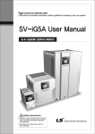
Starvert iG5A
0.4~1.5kW 1phase 200~230Volts
0.4~22kW 3Phase 200~230Volts
0.4~22kW 3Phase 380~480Volts
Automation Equipment
Inverter
STARVERT iG5A
LS Starvert iG5A is very competitive in its price and shows an upgraded functional
strength. User-friendly interface, extended inverter ranges up to 22kW,
superb torque competence and small size of iG5A provides an optimum use environment.
Standard
compliance
Compactness
iG5A
High
performance
Userfriendliness
& Easy
maintenance
2
Compact & Powerful Inverter iG5A
Contents
4
8
9
11
13
15
16
18
20
23
25
32
33
Overview
Model & Type
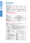
Standard Specifications
Wiring
Terminal Configurations
Keypad Features
Parameter Setting
Trial Run
Dimensions
Braking Resistors and Peripheral Devices
Function List
Protective Functions
Fault Remedy
3
iG5A
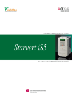
Powerful & Upgraded Performance
iG5A provides sensorless vector control, PID control,
and ground-fault protection through powerful built-in functions.
Sensorless vector control
Torque (%)
The built-in sensorless vector control provides
the superb speed control and powerful high
torque.
Speed vs Torque Characteristics
The ground-fault protection of output terminal
is possible during running.
Speed (Hz)
Ground-fault protection
during running
Vector Control Mode: Auto tuning Measure maximum
Condition: Sensorless
torque (%) at each speed (1/5/10/20/30/40/50/60Hz)
Analog control from -10V to 10V
Inputting analog signals from -10V to 10V
provides user-friendly operation.
+10
Forward
Reverse
-10
Built-in PID control
The built-in PID function enables to control
flow-rate, oil-pressure, temperature, etc
without any extra controller.
◀
◀
PID
PID
control
PIDcontrol
control
PIcontrol
control
PI
PI
control
Built-in dynamic braking circuit
Speed
With braking resistor
Normal state
◀
◀
The built-in dynamic braking circuit minimizes
deceleration time via braking resistors.
Time
Built-in 485 communication
The built-in RS-485 communication supports
remote control and monitoring between iG5A
and other equipment.
Wide product range
iG5A consists of the product range from 0.4 to 22KW.
4
Reducing
deceleration time
Compact & Powerful Inverter iG5A
RS-485 communication
Connected to PC
RS-485 - 232C converter
Monitoring
Checking operation status
(Voltage, Current, Frequency, etc)
Checking modified parameters
Windows support
Remote Control
Convenient remote control to modify operation status
(Forward/Reverse operation, Frequency, etc)
Easy parameter setting
Available to control up to 31 Inverters
RS-485, Modbus communication
Connected to XGT panel
Monitoring
Checking operation time
Automatic list-up of trip record
Language support (Korean, English, Chinese)
Remote Control
Convenient remote control to modify operation status
(Forward/Reverse operation, Frequency, etc)
Easy parameter setting
Available to control up to 31 Inverters
RS-485, Modbus communication
5
iG5A
User-friendly Interface & Easy Maintenance
The parameter setting becomes easier by adopting the 4 directions key. And iG5A supports
easy maintenance via diagnosis and fan changeable structure.
Diagnosis of output module
Through easy parameter setting, iG5A can diagnose the
status of output module.
Easy change of fan
iG5A is designed to be the fan changeable structure in
preparation for a fan breakdown.
Cooling fan control
By controlling the cooling fan, iG5A provides a virtually
quiet environment according to the status of operation.
User-friendly interface
The 4 directions key provides easy handling and
monitoring.
External loader (Optional)
The external loader away from a panel enables to control
and monitor conveniently. And the parameters made by
external loader can be copied and applicable to other
Inverters.
Loader type + External type (Optional)
Model name
INV, REMOTE KPD 2M (SV-iG5A)
INV, REMOTE KPD 3M (SV-iG5A)
INV, REMOTE KPD 5M (SV-iG5A)
6
Remarks
2m
3m
5m
Compact & Powerful Inverter iG5A
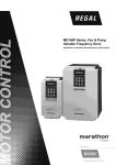
Compact Size
The compact size achieves cost-efficiency and various applications.
Same height from 0.4 to 4.0kW (128mm)
Global standard compliance
CE UL
Global standard
iG5A series complies with CE and UL standards.
PNP/NPN input
Both PNP and NPN inputs become possible and these enable to
use the outer power.
To do so, users will be given wider choices of selecting the
controller.
7
iG5A
Model & Type
Applicable motor ranges
1 Phase 200V
3 Phase 200V
3 Phase 400V
0.4kW (0.5HP)
SV004iG5A-1
SV004iG5A-2
SV004iG5A-4
0.75kW (1HP)
SV008iG5A-1
SV008iG5A-2
SV008iG5A-4
1.5kW (2HP)
SV015iG5A-1
SV015iG5A-2
SV015iG5A-4
2.2kW (3HP)
SV022iG5A-2
SV022iG5A-4
3.7kW (5HP)
SV037iG5A-2
SV037iG5A-4
4.0kW (5.4HP)
SV040iG5A-2
SV040iG5A-4
5.5kW (7.5HP)
SV055iG5A-2
SV055iG5A-4
7.5kW (10HP)
SV075iG5A-2
SV075iG5A-4
11.0kW (15HP)
SV110iG5A-2
SV110iG5A-4
15.0kW (20HP)
SV150iG5A-2
SV150iG5A-4
18.5kW (25HP)
SV185iG5A-2
SV185iG5A-4
22.0kW (30HP)
SV220iG5A-2
SV220iG5A-4
SV
015
iG5A
STARVERT
Motor rating (kW)
(004: 0.4kW~075: 7.5kW)
iG5A series
Input voltage
(1: 1 phase 200~230[V], 2: 3 phase 200~230[V], 3: 3 phase 380~480[V])
8
2
Compact & Powerful Inverter iG5A
Standard Specifications
1 Phase 200V
SV
Max.
capacity 1)
Output
rating
iG5A-1
004
008
0.5
1
2
(kW)
0.4
0.75
1.5
Capacity (kVA) 2)
0.95
1.9
3.0
FLA (A) 3)
2.5
5
8
4)
400 [Hz]
3 phase 200~230V 5)
Max frequency
Max voltage
1phase 200~230 VAC (+10%, -15%)
Rated voltage
Input
rating
015
(HP)
50~60 [Hz] (±5%)
Rated frequency
Cooling method
Forced air cooling
Weight (kg)
0.76
1.12
1.84
3 Phase 200V
SV
Max.
capacity 1)
Output
rating
iG5A-2
004
008
015
022
037
040
055
075
110
150
185
220
(HP)
0.5
1
2
3
5
5.4
7.5
10
15
20
25
30
(kW)
Capacity (kVA) 2)
0.4
0.75
1.5
2.2
3.7
4.0
5.5
7.5
11
15
18.5
22
0.95
1.9
3.0
4.5
6.1
6.5
9.1
12.2
17.5
22.9
28.2
33.5
FLA (A) 3)
2.5
5
8
12
16
17
32
46
60
74
88
Max frequency
3 phase 200~230V 5)
Max voltage
3 phase 200~230 (+10%, -15%)
Rated voltage
Input
rating
24
400 [Hz] 4)
50~60 [Hz] (±5%)
Rated frequency
Cooling method
N/C 6)
Weight (kg)
0.76
0.77
1.12
1.84
1.89
1.89
3.66
3.66
9.0
9.0
13.3
13.3
004
008
015
022
037
040
055
075
110
150
185
220
Forced air cooling
3 Phase 400V
SV
Max.
capacity 1)
iG5A-4
(HP)
0.5
1
2
3
5
5.4
7.5
10
15
20
25
30
(kW)
0.4
0.75
1.5
2.2
3.7
4.0
5.5
7.5
11
15
18.5
22
0.95
1.9
3.0
4.5
6.1
6.5
9.1
12.2
18.3
22.9
29.7
34.3
1.25
2.5
4
6
8
9
12
16
24
30
39
45
9.0
9.0
13.3
13.3
Capacity (kVA)
Output
rating
FLA (A) 3)
2)
4)
400 [Hz]
3 phase 380~480V 5)
Max frequency
Max voltage
Input
rating
3 phase 380~480 VAC (+10%, -15%)
Rated voltage
50~60 [Hz] (±5%)
Rated frequency
Cooling method
N/C 6)
Weight (kg)
0.76
Forced air cooling
0.77
1.12
1.84
1.89
1.89
3.66
3.66
1) Indicate the maximum applicable motor capacity when using 4 pole LS standard motor.
2) Rated capacity is based on 220V for 200V series and 440V for 400V series.
3) Refer to 15-3 of user’s manual when carrier frequency setting (39) is above 3kHz.
4) Max. frequency setting range is extended to 300Hz when H40 (Control mode select) is set to 3 (Sensorless vector control).
5) Max. output voltage cannot be higher than the input voltage. It can be programmable below input voltage.
6) Self-Cooling
9
iG5A
Standard Specifications
Control method
V/F, Sensorless vector control
Frequency setting resolution
Digital command: 0.01Hz
Analog command: 0.06Hz (Max. freq.: 60Hz)
Frequency accuracy
Digital command: 0.01% of Max. output frequency
Analog command: 0.1% of Max. output frequency
V/F pattern
Linear, Squared, User V/F
Overload capacity
150% per 1 min.
Torque boost
Manual/Auto torque boost
Control
Dynamic
braking
Max. braking
torque
20% 1)
Max. Duty
150% when using optional DB resistor 2)
Operation mode
Keypad/ Terminal/ Communication option/ Remote keypad selectable
Frequency setting
Analog: 0~10V, -10~10V, 0~20mA
Digital: Keypad
Operation features
PID, Up-down, 3-wire
NPN/PNP selectable
Input
Operation
Multi-function
terminal
P1~P8
FWD/REV RUN, Emergency stop, Fault reset, Jog operation, Multi-step Frequency-High, Mid, Low,
Multi-step Accel/Decel-High, Mid, Low, DC braking at stop, 2nd motor select, Frequency UP/Down,
3-wire operation, External trip A, B, PID-Inverter (V/F) operation bypass,
Option-inverter (V/F) operation bypass, Analog Hold, Accel/Decel stop
Open collector
terminal
Output
Environ
ment
0~10Vdc (less than 10mA): Output freq, Output current, Output voltage, DC link selectable
Trip
Over voltage, Under voltage, Over current, Ground fault current detection, Inverter overheat,
Motor overheat, Output phase open, Overload protection, Communication error,
Loss of speed command, Hardware fault, Fan trip
Alarm
Stall prevention, Overload
Momentary power loss
Below 15 msec.: Continuous operation (Should be within rated input voltage, rated output power.)
Above 15 msec.: Auto restart enable
Protection degree
IP 20, NEMA1 (Optional)
Ambient temp
-10℃~50℃
Storage temp
-20℃~65℃
Humidity
Below 90% RH (No condensation)
Altitude/Vibration
Below 1,000m, 5.9m/sec 2 (0.6G)
Atmospheric pressure
70~106 kPa
Location
Protected from corrosive gas, Combustible gas, Oil mist or dust
1) Means average braking torque during Decel to stop of a motor.
2) Refer to Chapter 16 of user’s manual for DB resistor specification.
10
Less than DC 24V, 50mA
(N.O., N.C.) Less than AC 250V, 1A; Less than DC 30V, 1A
Multi-function relay
Analog output (AM)
Protective
function
Fault output and
inverter status output
Compact & Powerful Inverter iG5A
Wiring
0.4~7.5kW
DB resistor
(Optional)
3 phase AC input
(Rated input voltage)
B1
B2
R
U
S
V
T
W
G
Ground
24 24V output
AM
Multi-function
analog output
signal: 0~10V
P1 FX (Forward run)
P2 RX (Reverse run)
CM
CM Input signal common
P3 BX (Emergency stop)
P4 RST (Trip reset)
P5 JOG (Jog operation)
3A A contact output
CM Input signal common
3C A/B contact common
P6 Multi-step freq. - Low
3B B contact output
P7 Multi-step freq. - Middle
P8 Multi-step freq. - High
MO Multi-function open
collector output
Potentiometer
(1kohm, 1/2W)
VR 10V power supply for potentiometer
V1 Freq. Setting Voltage signal input: -10~10V
I
MG MO Common
S+
Freq. Current signal input: 0~20mA
CM Input signal common
RS-485 communication terminal
S-
11
iG5A
Wiring
11.0~22.0kW
DC reactor
3 phase AC input
(Rated input voltage)
P1(+)
DB resistor
(Optional)
B1 B2
N(-)
R
U
S
V
T
W
G
Ground
24 24V output
AM
Multi-function
analog output
signal: 0~10V
P1 FX (Forward run)
P2 RX (Reverse run)
CM
CM Input signal common
P3 BX (Emergency stop)
P4 RST (Trip reset)
P5 JOG (Jog operation)
3A A contact output
CM Input signal common
3C A/B contact common
P6 Multi-step freq. - Low
3B B contact output
P7 Multi-step freq. - Middle
P8 Multi-step freq. - High
MO Multi-function open
collector output
Potentiometer
(1kohm, 1/2W)
VR 10V power supply for potentiometer
V1 Freq. Setting Voltage signal input: -10~10V
I
S+
Freq. Current signal input: 0~20mA
CM Input signal common
12
MG MO Common
RS-485 communication terminal
S-
Compact & Powerful Inverter iG5A
Terminal Configuration
Specifications for power terminal block wiring
R
T
B1
B2
U
V
• 5.5kW~7.5kW (3 phase)
B2
B1
U
• 1.5kW (1 phase)
• 0.4kW~1.5kW (3 phase)
• 0.4kW~0.75kW (1 phase)
R
S
T
W
B1
B2
U
V
S
B2
U
V
W
T
B1
B2
U
V
W
B1
B2
N(-)
U
V
W
W
R
S
• 11~22kW (3 phase)
V
W
R(L1)
R
B1
R
T
• 2.2~4.0kW (3 phase)
S(L2)
T(L3) P1(+)
T
R, S, T wire
U, V, W wire
Ground wire
mm2
AWG
mm2
AWG
mm2
AWG
Terminal
Screw Size
Screw Torque
(kgf.cm) / lb-in
SV004iG5A-1
2
14
2
14
3.5
12
M3.5
10/8.7
SV008iG5A-1
2
14
2
14
3.5
12
M3.5
10/8.7
SV015iG5A-1
2
14
2
14
3.5
12
M4
15/13
SV004iG5A-2
2
14
2
14
3.5
12
M3.5
10/8.7
SV008iG5A-2
2
14
2
14
3.5
12
M3.5
10/8.7
SV015iG5A-2
2
14
2
14
3.5
12
M3.5
10/8.7
SV022iG5A-2
2
14
2
14
3.5
12
M4
15/13
SV037iG5A-2
3.5
12
3.5
12
3.5
12
M4
15/13
SV040iG5A-2
3.5
12
3.5
12
3.5
12
M4
15/13
SV055iG5A-2
5.5
10
5.5
10
5.5
10
M5
32/28
SV075iG5A-2
8
8
8
8
5.5
10
M5
32/28
SV110iG5A-2
14
6
14
6
14
6
M6
30.7/26.6
SV150iG5A-2
22
4
22
4
14
6
M6
30.7/26.6
SV185iG5A-2
30
2
30
2
22
4
M8
30.5/26.5
SV220iG5A-2
38
2
30
2
22
4
M8
30.5/26.5
SV004iG5A-4
2
14
2
14
2
14
M3.5
10/8.7
SV008iG5A-4
2
14
2
14
2
14
M3.5
10/8.7
SV015iG5A-4
2
14
2
14
2
14
M4
15/13
SV022iG5A-4
2
14
2
14
2
14
M4
15/13
SV037iG5A-4
2
14
2
14
2
14
M4
15/13
SV040iG5A-4
2
14
2
14
2
14
M4
15/13
SV055iG5A-4
3.5
12
2
14
3.5
12
M5
32/28
SV075iG5A-4
3.5
12
3.5
12
3.5
12
M5
32/28
SV110iG5A-4
5.5
10
5.5
10
8
8
M5
30.7/26.6
SV150iG5A-4
14
6
8
8
8
8
M5
30.7/26.6
SV185iG5A-4
14
6
8
8
14
6
M6
30.5/26.5
SV220iG5A-4
22
4
14
6
14
6
M6
30.5/26.5
13
iG5A
Terminal Configuration
Control terminal specifications
MO MG
3A
Terminal
3B
3C
Description
24
P5
CM
P1
P6
P2
CM
P7
P8
Wire size (mm2)
Single wire
Stranded
P3
VR
P4
S-
S+
I
AM
V1
1)
Screw size
Torque (Nm)
Multi-function input T/M 1-8
1.0
1.5
M2.6
0.4
CM
Common terminal
1.0
1.5
M2.6
0.4
VR
Power supply for external
potentiometer
1.0
1.5
M2.6
0.4
Output voltage: 12V
Max. output current: 100mA
Potentiometer: 1~5kohm
V1
Input terminal for voltage operation
1.0
1.5
M2.6
0.4
Max. input voltage:
-12V~+12V input
I
Input terminal for current operation
1.0
1.5
M2.6
0.4
0~20mA input
Internal resistor: 500ohm
AM
Multi-function analog output terminal
1.0
1.5
M2.6
0.4
Max. output voltage: 11V
Max. output current: 100mA
MO
Multi-function terminal for open collector
1.0
1.5
M2.6
0.4
Below DC 26V,100mA
MG
Ground terminal for external power supply
1.0
1.5
M2.6
0.4
24
24V external power supply
1.0
1.5
M2.6
0.4
Max. output current: 100mA
3A
Multi-function relay output A contact
1.0
1.5
M2.6
0.4
Below AC 250V, 1A
3B
Multi-function relay output B contact
1.0
1.5
M2.6
0.4
Below DC 30V, 1A
3C
Common for multi-function relays
1.0
1.5
M2.6
0.4
P1~P8
1) Use the recommended tightening torque when securing terminal screws.
※ When you use external power supply (24V) for multi-function input terminal (P1~P8), apply voltage higher than 12V to activate.
※ Tie the control wires more than 15cm away from the control terminals. Otherwise, it interferes front cover reinstallation.
14
Specification
Compact & Powerful Inverter iG5A
Keypad Features
Display
KEY
LED
1)
Description
Term
RUN
Run key
Run command
STOP/RESET
STOP/RESET key
STOP: Stop command during operation,
RESET: Reset command when a fault occurs.
▲
Up key
Used to scroll through codes or increase parameter value
▼
Down key
Used to scroll through codes or decrease parameter value
▶
Right key
Used to jump to other parameter groups or move a cursor to
the right to change the parameter value
◀
Left key
Used to jump to other parameter groups or move a cursor to
the left to change the parameter value
●
Enter key
Used to set the parameter value or save the changed parameter value
FWD
Forward run
Lit during forward run
REV
Reverse run
Lit during reverse run
RUN
Run key
Lit during operation
SET
Setting
Lit during parameter setting
1) 4 LEDs above are set to blink when a fault occurs.
RUN
STOP
RESET
65.6
FWD
REV
36.2
SET
RUN
72.4
2-Ø4.5
3.4
95
83
70
CL
Dimensions
ENT
5
2.1
13.9
23.1
15
iG5A
Moving to Other Groups
Parameter groups
There are 4 different parameter groups in iG5A series as shown below.
Parameter group
Description
Drive group
Basic parameters necessary for the inverter to run. Parameters such as Target frequency, Accel/Decel time settable.
Function group 1
Basic function parameters to adjust output frequency and voltage.
Function group 2
Advanced function parameters to set parameters for such as PID Operation and second motor operation.
I/O (Input/Output) group
Parameters necessary to make up a sequence using multi-function input/output terminal.
Moving to other groups
Moving to other groups using the Right (▶) key
Moving to other groups using the Left (◀) key
1)
1) Target frequency can be set at 0.0 (the 1st code of drive group). Even though the preset value is 0.0, it is user-settable.
The changed frequency will be displayed after it is changed.
16
1)
Compact & Powerful Inverter iG5A
When changing ACC time from 5.0 sec to 16.0 sec
1
・In the first code“0.00”, press the Up (▲) key once to go to the second code.
2
・ACC [Accel time] is displayed.
・Press the Ent (●) key once.
3
・Preset value is 5.0, and the cursor is in the digit 0.
・Press the Left (◀) key once to move the cursor to the left.
4
・The digit 5 in 5.0 is active. Then press the Up (▲) key once.
5
・The value is increased to 6.0
・Press the Left (◀) key to move the cursor to the left.
6
・0.60 is displayed. The first 0 in 0.60 is active.
・Press the Up (▲) key once.
7
・16.0 is set.
・Press the Ent (●) key once.
・16.0 is blinking. 1)
・Press the Ent (●) key once again to return to the parameter name.
8
・ACC is displayed. Accel time is changed from 5.0 to 16.0 sec.
1) Pressing the Left (◀)/Right (▶)/Up (▲)/Down (▼) key while a cursor is blinking will cancel the parameter value change.
Pressing the Ent (●) key in this status will enter the value into memory.
※ In step 7, pressing the Left (◀) or Right (▶) key while 16.0 is blinking will disable the setting.
Code change in Drive group
1
・In the 1st code in Drive group“0.00”,
press the Up (▲) key once.
2
・The 2nd code in Drive group“ACC”is displayed.
・Press the Up (▲) key once.
3
・The 3rd code“dEC”in Drive group is displayed.
・Keep pressing the Up (▲) key until the last code appears.
4
・The last code in Drive group "drC”is displayed.
・Press the Up (▲) key again.
5
・Return to the first code of Drive group.
・Use Down (▼) key for the opposite order.
17
iG5A
Trial Run
Multi-step operation + Run/Stop via FX/RX + Max. frequency change
Operation condition
Operation command:
Run/Stop via FX/RX
Frequency command:
Multi-step operation [Low (20), Middle (30), High (80)]
Max. frequency change:
From 60Hz to 80Hz
Wiring
P1 (Forward)
S1
P2 (Reverse)
S2
3 phase
AC input
P6 (Low)
S3
R
U
S
V
T
W
G
P7 (Middle)
S4
S/W
P8 (High)
S5
P1 (Forward)
P2 (Reverse)
CM
P6 (Low)
P7 (Middle)
P8 (High)
CM
1. Please make sure that R, S, T are connected to 3 phase AC input, and
U, V, W are also motor connection terminals.
2. After supplying the power, please set the frequency of multi-step among
Low, Middle, and High.
VR
V1
3. If P1 (FX) turns on, the motor operates in forward. And after turning off,
it stops according to the deceleration time.
CM
4. If P2 (RX) turns on, the motor operates in reverse. And after turning off,
it stops according to the deceleration time.
Parameter setting
18
Step
Command
Code
1
Max. frequency change (FU1)
F21
2
Multi-step frequency (DRV)
st1
3
Multi-step frequency (DRV)
4
Description
Default
After change
Change Max. frequency.
60Hz
80Hz
Set‘Low’step.
10Hz
20Hz
st2
Set‘Middle’step.
20Hz
30Hz
Multi-step frequency (I/O)
I30
Set‘High’step.
30Hz
80Hz
5
Forward run (P1: FX)
I17
The default is FX. This value may change.
FX
FX
6
Reverse run (P2: RX)
I18
The default is RX. This value may change.
RX
RX
Compact & Powerful Inverter iG5A
Potentiometer (Volume) + Run/Stop via FX/RX + Accel/Decel time change
Operation condition
Operation command:
Run/Stop via FX/RX
Frequency command:
0~60Hz analog input via potentiometer
Accel/Decel time:
Accel-10sec, Decel-20sec
Wiring
Potentiometer 1~5kohm, 1/2W
Motor
3
VR
1
R
S
T
G
3 phase
AC input
2
V1
CM
U
V
W
0~60Hz
P1 (FX) Forward
P2 (RX) Reverse
CM
1. Please make sure that R, S, T are connected to 3 phase AC input,
and U, V, W are also motor connection terminals.
2. After supplying the power, please set the frequency of multi-step
among Low, Middle, and High.
3. If P1 (FX) turns on, the motor operates in forward. And after
turning off, it stops according to the deceleration time.
VR
V1
CM
Potentiometer
1~5kohm, 1/2W
4. If P2 (RX) turns on, the motor operates in reverse. And after
turning off, it stops according to the deceleration time.
5. Control the motor’s speed via potentiometer.
Parameter setting
Step
Command
Code
1
Operation command
(DRV group)
Description
Drv
Turn on/off motor via terminal.
1 (FX/RX-1)
1 (FX/RX-1)
2
Analog input
(DRV group)
Frq
Change keypad command to analog voltage command.
0 (Keypad-1)
3 (V1: 0~10V)
3
Accel/Decel time
(DRV group)
ACC
dEC
Set Accel time to 10sec in ACC
5sec (Accel)
10sec (Decel)
10sec (Accel)
20sec (Decel)
4
Forward run
(P1: FX)
I17
The default is FX. This value may change
FX
FX
5
Reverse run
(P2: RX)
I18
The default is RX. This value may change.
RX
RX
Set Decel time to 20sec in dEC.
Default
After change
19
iG5A
Dimensions
SV004iG5A-2 / SV008iG5A-2, SV004iG5A-4 / SV008iG5A-4
W
A
A
W1
H1
Ø
H
D
B
W1
mm (inches)
Inverter model
(kW)
W (mm)
W1 (mm)
H (mm)
H1 (mm)
D (mm)
Ø
A (mm)
B (mm)
(kg)
SV004IG5A-2
SV008IG5A-2
SV004IG5A-4
SV008IG5A-4
0.4
0.75
0.4
0.75
70
70
70
70
65.5
65.5
65.5
65.5
128
128
128
128
119
119
119
119
130
130
130
130
4.0
4.0
4.0
4.0
4.5
4.5
4.5
4.5
4.0
4.0
4.0
4.0
0.76
0.77
0.76
0.77
SV015iG5A-2 / SV015iG5A-4
W
W1
A1
A
H1
Ø
H
D
B
W1
mm (inches)
Inverter model
(kW)
W (mm)
W1 (mm)
H (mm)
H1 (mm)
D (mm)
Ø
A (mm)
B (mm)
(kg)
SV015IG5A-2
SV015IG5A-4
1.5
1.5
100
100
95.5
95.5
128
128
120
120
130
130
4.5
4.5
4.5
4.5
4.5
4.5
1.12
1.12
20
Compact & Powerful Inverter iG5A
SV022iG5A-2 / SV037iG5A-2 / SV040iG5A-2, SV022iG5A-4 / SV037iG5A-4 / SV040iG5A-4
W
A
Ø
H1
CL
H
D
B
B
W1
mm (inches)
Inverter model
(kW)
W (mm)
W1 (mm)
H (mm)
H1 (mm)
D (mm)
Ø
A (mm)
B (mm)
(kg)
SV022IG5A-2
SV037IG5A-2
SV040IG5A-2
SV022IG5A-4
SV037IG5A-4
SV040IG5A-4
2.2
3.7
4.0
2.2
3.7
4.0
140
140
140
140
140
140
132
132
132
132
132
132
128
128
128
128
128
128
120.5
120.5
120.5
120.5
120.5
120.5
155
155
155
155
155
155
4.5
4.5
4.5
4.5
4.5
4.5
4.5
4.5
4.5
4.5
4.5
4.5
4.5
4.5
4.5
4.5
4.5
4.5
1.84
1.89
1.89
1.84
1.89
1.89
SV055iG5A-2 / SV075iG5A-2, SV055iG5A-4 / SV075iG5A-4
W
A
W
Ø
A
H1
H
D
B
B
W
mm (inches)
Inverter model
(kW)
W (mm)
W1 (mm)
H (mm)
H1 (mm)
D (mm)
Ø
A (mm)
B (mm)
(kg)
SV055IG5A-2
SV075IG5A-2
SV055IG5A-4
SV075IG5A-4
5.5
7.5
5.5
7.5
180
180
180
180
170
170
170
170
220
220
220
220
210
210
210
210
170
170
170
170
4.5
4.5
4.5
4.5
5
5
5
5
4.5
4.5
4.5
4.5
3.66
3.66
3.66
3.66
21
iG5A
Dimensions
SV110iG5A-2 / SV150iG5A-2 / SV110iG5A-4 / SV150iG5A-4
W
W1
A
Ø
A
H1
H
D
B
B
W1
mm (inches)
Inverter model
(kW)
W (mm)
W1 (mm)
H (mm)
H1 (mm)
D (mm)
Ø
A (mm)
B (mm)
(kg)
SV110iG5A-2
SV150iG5A-2
SV110iG5A-4
SV150iG5A-4
11.0
15.0
11.0
15.0
235
235
235
235
219
219
219
219
320
320
320
320
304
304
304
304
189.5
189.5
189.5
189.5
7.0
7.0
7.0
7.0
8.0
8.0
8.0
8.0
7.0
7.0
7.0
7.0
9.00
9.00
9.00
9.00
SV185iG5A-2 / SV220iG5A-2 / SV185iG5A-4 / SV220iG5A-4
W
Ø A
W1
A
H1
H
D
B
W1
B
mm (inches)
Inverter model
(kW)
W (mm)
W1 (mm)
H (mm)
H1 (mm)
D (mm)
Ø
A (mm)
B (mm)
(kg)
SV185iG5A-2
SV220iG5A-2
SV185iG5A-4
SV220iG5A-4
18.5
22.0
18.5
22.0
260
260
260
260
240
240
240
240
410
410
410
410
392
392
392
392
208.5
208.5
208.5
208.5
10.0
10.0
10.0
10.0
10.0
10.0
10.0
10.0
10.0
10.0
10.0
10.0
13.3
13.3
10.0
10.0
22
Compact & Powerful Inverter iG5A
Braking Resistors and Peripheral Devices
Braking resistors
Voltage
100% braking
Inverter
0.4
0.75
1.5
2.2
3.7
5.5
7.5
11.0
15.0
18.5
22.0
0.4
0.75
1.5
2.2
3.7
5.5
7.5
11.0
15.0
18.5
22.0
200V Series
400V Series
150% braking
Resistor [Ω]
Watt [W]1)
Resistor [Ω]
400
200
100
60
40
30
20
15
11
9
8
1,800
900
450
300
200
120
90
60
45
35
30
50
100
200
300
500
700
1,000
1,400
2,000
2,400
2,800
50
100
200
300
500
700
1,000
1,400
2,000
2,400
2,800
300
150
60
50
33
20
15
10
8
5
5
1,200
600
300
200
130
85
60
40
30
20
20
Watt [W] 1)
100
150
300
400
600
800
1,200
2,400
2,400
3,600
3,600
100
150
300
400
600
1,000
1,200
2,000
2,400
3,600
3,600
1) The wattage is based on Enable Duty (%ED) with continuous braking time 15sec.
Breakers
Model
004iG5A-1
008iG5A-1
015iG5A-1
004iG5A-2
004iG5A-2
008iG5A-2
015iG5A-2
022iG5A-2
037iG5A-2
040iG5A-2
055iG5A-2
075iG5A-2
110iG5A-2
150iG5A-2
Breaker
Current [A]
ABS33b,EBs33
ABS33b,EBs33
ABS33b,EBs33
ABS33b,EBs33
ABS33b,EBs33
ABS33b,EBs33
ABS33b,EBs33
ABS33b,EBs33
ABS33b,EBs33
ABS33b,EBs33
ABS53b,EBs53
ABS103b,EBs53
ABS103b,EBs53
ABS203b,EBs53
Voltage [V]
GMC-12
GMC-12
GMC-12
GMC-12
GMC-12
GMC-12
GMC-12
GMC-18
GMC-22
GMC-22
GMC-22
GMC-32
GMC-50
GMC-65
Model
185iG5A-2
220iG5A-2
004iG5A-4
008iG5A-4
015iG5A-4
022iG5A-4
037iG5A-4
040iG5A-4
055iG5A-4
075iG5A-4
110iG5A-4
150iG5A-4
185iG5A-4
220iG5A-4
Breaker
Current [A]
ABS203b,EBs53
ABS203b,EBs53
ABS33b,EBs33
ABS33b,EBs33
ABS33b,EBs33
ABS33b,EBs33
ABS33b,EBs33
ABS33b,EBs33
ABS33b,EBs33
ABS33b,EBs33
ABS53b,EBs53
ABS103b,EBs53
ABS103b,EBs53
ABS103b,EBs53
Voltage [V]
GMC-85
GMC-100
GMC-12
GMC-12
GMC-12
GMC-22
GMC-22
GMC-22
GMC-22
GMC-22
GMC-22
GMC-25
GMC-40
GMC-50
23
iG5A
Braking Resistors and Peripheral Devices
Fuses & AC reactors
Model
004iG5A-1
008iG5A-1
015iG5A-1
004iG5A-2
008iG5A-2
015iG5A-2
022iG5A-2
037iG5A-2
040iG5A-2
055iG5A-2
075iG5A-2
110iG5A-2
150iG5A-2
185iG5A-2
220iG5A-2
004iG5A-4
008iG5A-4
015iG5A-4
022iG5A-4
037iG5A-4
040iG5A-4
055iG5A-4
075iG5A-4
110iG5A-4
150iG5A-4
185iG5A-4
220iG5A-4
24
AC external fuse
Current [A]
Voltage [V]
10 A
10 A
15 A
10 A
10 A
15 A
25 A
30 A
30 A
30 A
50 A
70 A
100 A
100 A
125 A
5A
10 A
10 A
10 A
20 A
20 A
20 A
30 A
35 A
45 A
60 A
70 A
500V
500V
500V
500V
500V
500V
500V
500V
500V
500V
500V
500V
500V
500V
500V
500V
500V
500V
500V
500V
500V
500V
500V
500V
500V
500V
500V
AC reactor
DC reactor
4.20 mH, 3.5 A
2.13 mH, 5.7 A
1.20 mH, 10 A
4.20 mH, 3.5 A
2.13 mH, 5.7 A
1.20 mH, 10 A
0.88 mH, 14 A
0.56 mH, 20 A
0.56 mH, 20 A
0.39 mH, 30 A
0.28 mH, 40 A
0.20 mH, 59 A
0.15 mH, 75 A
0.12 mH, 96 A
0.10 mH, 112 A
18.0 mH, 1.3 A
8.63 mH, 2.8 A
4.81 mH, 4.8 A
3.23 mH, 7.5 A
2.34 mH, 10 A
2.34 mH, 10 A
1.22 mH, 15 A
1.14 mH, 20 A
0.81 mH, 30 A
0.61 mH, 38 A
0.45 mH, 50 A
0.39 mH, 58 A
0.74 mH, 56 A
0.57 mH, 71 A
0.49 mH, 91 A
0.42 mH, 107 A
2.76 mH, 29 A
2.18 mH, 36 A
1.79 mH, 48 A
1.54 mH, 55 A
Compact & Powerful Inverter iG5A
Function List
Drive Group
LED
display
ACC
dEC
Parameter
name
During stop: Frequency command
During run: Output frequency
Accel time
Decel time
drv
Drive mode
Frq
Frequency setting method
St1
St2
St3
CUr
rPM
dCL
vOL
nOn
drC
Drv2
Multi-Step frequency 1
Multi-Step frequency 2
Multi-Step frequency 3
Output current
Motor RPM
Inverter DC link voltage
User display select
Fault display
Direction of motor rotation select
Drive mode 2
Frq2
Frequency setting method 2
rEF
Fbk
Reference value for PID
Feedback value for PID
0.00
Factory
default
Adj. during
run
0~400Hz
0.00
Yes
0~6000sec
5.0
10.0
Yes
Yes
0 (Keypad), 1 (FX/RX-1), 2 (FX/RX-2), 3 (RS-485)
1
No
0 (Keypad-1), 1 (Keypad-2), 2 (V1S: -10~10V), 3 (V1: 0~10V)
4 (I: 0~20mA), 5 (V1S+1), 6 (V1+I), 7 (RS-485), 8 (Digital volume)
0
No
10.00
20.00
30.00
–
–
–
vOL
nOn
F
1
Yes
Yes
Yes
–
–
–
–
–
Yes
No
0
No
0.00
-
Yes
-
Factory
default
1
Adj. during
run
Yes
0
No
Description
0~400Hz
A
rpm
V
vOL, Por, tOr
F (Forward), R (Reverse)
0 (Keypad), 1 (FX/RX-1), 2 (FX/RX-2)
0 (Keypad-1), 1 (Keypad-2), 2 (V1S-: 10~10V), 3 (V: 0~10V)
4 (I: 0~20mA), 5 (V1S+I), 6 (V1+I), 7 (RS-485)
0 ~ 400 [Hz] or 0 ~ 100 [%]
-
Function group 1
LED
display
F0
Parameter
name
Description
Jump code
0~71
F1
Forward/Reverse run disable
0 (Fwd and rev run enable), 1 (Forward run disable), 2 (Reverse run disable)
F2
Accel pattern
F3
Decel pattern
F4
Stop mode select
0 (Decelerate to stop), 1 (DC brake to stop), 2 (Free run to stop), 3 (Power braking)
0
No
F8 1)
DC brake start frequency
Start frequency, 0~60Hz
5.00
No
F9
DC brake wait time
0.1~60sec
0.1
No
F10
DC brake voltage
0~200%
50
No
F11
DC brake time
0~60sec
1.0
No
F12
DC brake start voltage
0~200%
50
No
F13
DC brake start time
0~60sec
0
No
F14
Time for magnetizing a motor
0~60sec
1.0
No
F20
Jog frequency
0~400Hz
10.00
Yes
F21 2)
Max. frequency
40~400Hz
60.00
No
F22
Base frequency
30~400Hz
60.00
No
F23
Start frequency
0.1~10Hz
0.50
No
F24
Frequency high/low limit select
0 (NO),1 (YES)
0 (No)
No
F25 3)
Frequency high limit
Frequency low limit~frequency high limit
60.00
No
F26
Frequency low limit
0~frequency high limit
0.50
No
0 (Linear), 1 (S-curve)
0
0
No
1) Only displayed when F4 is set to 1 (DC brake to stop).
2) If H40 is set to 3 (Sensorless vector), Max. frequency is settable up to 300Hz.
3) Only displayed when F24 (Frequency high/low limit select) is set to 1.
25
iG5A
Function List
Function group 1
LED
display
F27
F28
F29
F30
F31 1)
F32
F33
F34
F35
F36
F37
F38
F39
F40
F50
F51 2)
F53
F54
F55
F56
F57
F58
Parameter
name
Torque Boost select
Torque boost in forward direction
Torque boost in reverse direction
V/F pattern
User V/F frequency 1
User V/F voltage 1
User V/F frequency 2
User V/F voltage 2
User V/F frequency 3
User V/F voltage 3
User V/F frequency 4
User V/F voltage 4
Output voltage adjustment
Energy-saving level
Electronic thermal select
Electronic thermal level for 1 minute
Electronic thermal level for
continuous
Motor cooling method
Overload warning level
Overload warning time
Overload trip select
Overload trip level
Overload trip time
F59
Stall prevention select
F60
Stall prevention level
When Stall prevention during
deceleration, voltage limit select
Save up/down frequency select
Save up/down frequency
F52
F61
F63
F64
F65
Up down mode select
F66
Up-down step frequency
F70
Draw run mode select
F71
Draw rate
1) Set F30 to 2 (User V/F) to display this parameter.
2) Set F50 to 1 to display this parameter.
26
Factory
default
0
5
5
0
15.00
25
30.00
50
45.00
75
60.00
100
100
0
0
150
Adj. during
run
No
No
No
No
No
No
No
No
No
No
No
No
No
Yes
Yes
Yes
50~200%
100
Yes
0 (Self-cooling), 1 (Post-cooling)
30~150%
0~30sec
0 (NO), 1 (YES)
30~200%
0~60sec
0: Stall prevention disabled
1: During Accel
2: During constant run
3: During Accel, During constant run
4: During Decel
5: During Accel, During Decel
6: During Decel, During constant run
7: During Accel, During constant run, During Decel
30~200%
0
150
10
1
180
60
Yes
Yes
Yes
Yes
Yes
Yes
0
No
150
No
0~1
0
No
0~1
0
0.00
No
No
0
No
0.00
No
0
No
0.0
Yes
Description
0 (Manual torque boost), 1 (Auto torque boost)
0~15%
0 (Linear), 1 (Square), 2 (User V/F)
0~User V/F frequency2 [Hz]
0~100%
User V/F frequency1~User V/F frequency3 [Hz]
0~100%
User V/F frequency2~User V/F frequency4 [Hz]
0~100%
User V/F frequency3~Max. frequency [Hz]
0~100%
40~110%
0~30%
0 (NO), 1 (YES)
50~200%
0: Increases goal frequency as a standard of Max.
frequency/Min.frequency
1: Increases as many as step frequency
according to edge input
2: Available to combine 1 and 2
0 ~ 400 [Hz]
0: Inverter doesn’t run as a draw mode
1: V1(0~10V) input draw run
2: I(0~20mA) input draw run
3: V1(-10~10V) input draw run
0 ~ 100 [%]
iG5A
Function List
Function group 2
LED
display
H32
H33
H34
H36
H37
H39
Parameter
name
Rated slip frequency
Motor rated current
No load motor current
Motor efficiency
Load inertia rate
Carrier frequency select
H40
Control mode select
H41
H42
H44
H45 2)
H46
H47
Auto tuning
Stator resistance (Rs)
Leakage inductance (Ls)
Sensorless P gain
Sensorless I gain
Sensorless torque limit
H48
PWM mode select
H49
H50 3)
H51
H52
H53
H54
H55
H56
PID control select
PID Feedback select
P gain for PID controller
Integral time for PID controller (I gain)
Differential time for PID controller (D gain)
F gain for PID controller
PID output frequency limit
PID output frequency low limit
H57
PID standard value select
H58
PID control unit select
H60
Diagnosis select
H61
H62
H63
H64
H65
H66
H67
H70
H71
Sleep delay time
Sleep frequency
Wake up level
KEB drive select
KEB action start level
KEB action stop level
KEB action gain
Frequency reference for accel/decel
Accel/Decel time scale
H72
Power on display
H73
Monitoring item select
H74
Gain for motor rpm display
H75
DB resistor operating rate limit select
H76
DB resistor operating rate
Description
0~10Hz
1.0~150 [A]
0.1~50 [A]
50~100%
0~2
1~15kHz
0 (Volts/frequency control), 1 (Slip compensation control),
2 (PID feedback control), 3 (Sensorless vector control)
0 (NO), 1 (YES)
0~28 [Ω]
0~300.0mH
0~32767
100~220 [%]
0: Normal PWM mode
1: 2 phase PWM mode
0~1
0 (1: 0~20mA), 1 (V1 0~10V)
0~999.9%
0.1~32.0sec
0.1~30.0sec
0~999.9%
0.1~400Hz Max. frequency
0.1~400 [Hz]
0: Loader digital setting 1
1: Loader digital setting 2
2: V1 terminal setting 2: 0~10V
3: I terminal setting: 0~20mA
4: Setting as a RS-485 communication
0: Frequency [Hz]
1: Percentage [%]
0: Diagnosis disabled
1: IGBT fault/ Ground-fault
2: Output phase short & Output open/ Ground-fault
3: Ground-fault
0~2000 [sec]
0~400 [Hz]
0~100 [%]
0~1
110~140 [%]
110~145 [%]
1~20,000
0 (Based on Max. frequency), 1 (Based on delta frequency)
0 (0.01 sec), 1 (0.1 sec), 2 (1 sec)
0: Frequency command
9: Motor rpm
1: Accel time
10: Inverter DC link voltage
2: Decel time
11: User display select (H73)
3: Drive mode
12: Fault display
4: Frequency mode
13: Direction of motor rotation select
5: Multi-Step frequency 1 14: Output current 2
6: Multi-Step frequency 2 15: Motor rpm 2
7: Multi-Step frequency 3 16: Inverter DC link voltage 2
8: Output current
17: User display select 2
0: Output voltage [V]
1: Output power [kW]
2: Torque [kgf・m]
1~1000%
0: Unlimited
1: Use DB resistor for the H76 set time.
0~30%
1) H32~H36 factory default values are set based on LS motor.
2) Set H40 to 3 (Sensorless vector control) to display this parameter.
3) Set H40 to 2 (PID control) to display this parameter.
28
Factory
default
– 1)
–
–
–
0
3kHz
Adj. during
run
No
No
No
No
No
Yes
0
No
–
–
1000
100
0
180.0
No
No
Yes
Yes
No
No
0
No
0
No
300%
1sec
0sec
0%
60Hz
0.50
Yes
Yes
Yes
Yes
Yes
Yes
0
No
0
No
0
No
60.0
0.00
35.0
0
125.0
130.0
1000
0
1 (0.1 sec)
No
Yes
Yes
No
No
No
No
No
Yes
0
Yes
0
Yes
100%
Yes
1
Yes
10%
Yes
Compact & Powerful Inverter iG5A
Function group 2
LED
display
H90
H91
H92
H93
H94
Parameter
name
Cooling fan control
Operating method select
when cooling fan malfunctions
S/W version
2nd motor Accel time
2nd motor Decel time
2nd motor base frequency
2nd motor V/F pattern
2nd motor forward torque
boost
2nd motor reverse torque
boost
2nd motor stall prevention
level
2nd motor Electronic thermal
level for 1 min
2nd motor Electronic thermal
level for continuous
2nd motor rated current
Parameter read
Parameter write
Parameter initialize
Password register
H95
Parameter lock
H77 1)
H78
H79
H81
H82
H83
H84
H85
H86
H87
H88
H89
0 (Always ON), 1 (Keep ON when its Temp. is higher than Inverter protection limit Temp.)
Factory
default
0
Adj. during
run
Yes
0 (Run when cooling fan malfunctions), 1 (Stop when cooling fan malfunctions)
0
Yes
1.0
5.0
10.0
60.00
0
No
Yes
Yes
No
No
5
No
5
No
30~150%
150%
No
50~200%
150%
Yes
50~150%
100%
Yes
0.1~100 [A]
0~1
0~1
0~5
0~FFFF
26.3
0
0
0
0
No
No
No
No
Yes
0
Yes
Description
0~10.0
0~6000sec
30~400Hz
0 (Linear),1 (Square), 2 (User V/F)
0~15%
0~FFFF
UL (Unlock)
L (Lock)
Parameter change enable
Parameter change disable
1) Exception SV004iG5A-2/SV004iG5A-4 adopt self-cooling type, so this code is hidden.
Input/output group
LED
display
I0
I1
I2
I3
I4
I5
I6
I7
I8
I9
I10
I11
I12
I13
I14
I15
Parameter
name
Jump code
Filter time constant for NV input
NV input Min. voltage
Frequency corresponding to I2
NV input Max. voltage
Frequency corresponding to I4
Filter time constant for V1 input
V1 input Min. voltage
Frequency corresponding to I7
V1 input Max. voltage
Frequency corresponding to I9
Filter time constant for I input
I input Min. current
Frequency corresponding to I12
I input Max. current
Frequency corresponding to I14
Description
0~87
0~9999
0~-10V
0~Max. frequency [Hz]
0~-10V
0~Max. frequency [Hz]
0~9999
0~10V
0~Max. frequency [Hz]
0~10V
0~Max. frequency [Hz]
0~9999
0~20mA
0~Max. frequency [Hz]
0~20mA
0~Max. frequency [Hz]
Factory
default
1
10
0.00
0.00
10.0
60.00
10
0
0.00
10
60.00
10
4.00
0.00
20.00
60.00
Adj. during
run
Yes
Yes
Yes
Yes
Yes
Yes
Yes
Yes
Yes
Yes
Yes
Yes
Yes
Yes
Yes
Yes
29
iG5A
Function List
Input/output group
LED
display
Parameter
name
I16
Criteria for analog input signal loss
I17
Multi-function input terminal
P1 define
I18
Multi-function input terminal
P2 define
I19
Multi-function input terminal
P3 define
I20
Multi-function input terminal
P4 define
I21
Multi-function input terminal
P5 define
I22
Multi-function input terminal
P6 define
I23
Multi-function input terminal
P7 define
I24
Multi-function input terminal
P8 define
30
I25
Input terminal status display
I26
Output terminal status display
I27
Filtering time constant for
multi-function input terminal
I30
I31
I32
I33
I34
I35
I36
I37
I38
I39
I40
I41
I42
I43
I44
I45
I46
I47
Multi-step frequency 4
Multi-step frequency 5
Multi-step frequency 6
Multi-step frequency 7
Multi-Accel time 1
Multi-Decel time 1
Multi-Accel time 2
Multi-Decel time 2
Multi-Accel time 3
Multi-Decel time 3
Multi-Accel time 4
Multi-Decel time 4
Multi-Accel time 5
Multi-Decel time 5
Multi-Accel time 6
Multi-Decel time 6
Multi-Accel time 7
Multi-Decel time 7
I50
Analog output item select
Description
0: Disabled
1: activated below half of set value.
2: activated below set value.
0: Forward run command
1: Reverse run command
2: Emergency stop trip
3: Reset when a fault occurs {RST}
4: Jog operation command
5: Multi-step freq - Low
6: Multi-step freq - Mid
7: Multi-step freq - High
8: Multi Accel/Decel - Low
9: Multi Accel/Decel - Mid
10: Multi Accel/Decel - High
11: DC brake during stop
12: 2nd motor select
13: -Reserved14: -Reserved15: Up-down Frequency increase (UP)command
16: Up-down Frequency decrease command (DOWN)
17: 3-wire operation
18: External trip A contact (EtA)
19: External trip B contact (EtB)
20: 21: Exchange between PID operation and V/F operation
22: Exchange between option and Inverter
23: Analog hold
24: Accel/Decel disable
25: Up/Down save freq. Initialization
26: JOG-FX 8-3
27: JOG-RX
BIT7
P8
BIT6 BIT5
P7
P6
BIT1
3AC
BIT4
P5
BIT3
P4
BIT2 BIT1
P3
P2
BIT0
MO
2~50
0~Max. frequency [Hz]
0~6000sec
0 (Output freq.), 1 (Output current)
2 (Output voltage), 3 (Inverter DC link voltage)
BIT0
P1
Factory
default
Adj. during
run
0
Yes
0
Yes
1
Yes
2
Yes
3
Yes
4
Yes
5
Yes
6
Yes
7
Yes
-
-
-
-
15
Yes
30.00
25.00
20.00
15.00
3.0
3.0
4.0
4.0
5.0
5.0
6.0
6.0
7.0
7.0
8.0
8.0
9.0
9.0
Yes
Yes
Yes
Yes
Yes
Yes
Yes
Yes
Yes
Yes
Yes
Yes
Yes
Yes
Yes
Yes
Yes
Yes
-
Yes
Compact & Powerful Inverter iG5A
Input/output group
LED
display
I51
I52
I53
I54
Parameter
name
Analog output level adjustment
Frequency detection level
Frequency detection bandwidth
Multi-function output terminal select
I55
Fault relay select
I56
Fault relay output
I57
Output terminal select when
communication error occurs
I59
I60
Communication protocol select
Inverter number
I61
Baud rate
I62
Drive mode select after loss
of frequency command
I63
I64
Wait time after loss of
frequency command
Communication time setting
Factory
default
100
30.00
10.00
12
Adj. during
run
Yes
Yes
Yes
Yes
17
Yes
2
Yes
0
Yes
0
1
No
Yes
3
Yes
0
Yes
0.1~120 sec
1.0
Yes
2~100msec
5
Yes
Description
10~200%
0~400Hz
0: FDT-1
1: FDT-2
2: FDT-3
3: FDT-4
4: FDT-5
5: Overload (OL)
6: Inverter overload (IOL)
7: Motor stall (STALL)
8: Over voltage trip (OV)
9: Low voltage trip (LV)
10: Inverter overheat (OH)
11: Command loss
12: During run
13: During stop
14: During constant run
15: During speed searching
16: Wait time for run signal input
17: Fault relay select
18: Warning for cooling fan trip
19: Brake signal select
0: 1: When the low voltage trip occurs
2: When the trip other than low voltage trip occurs
3: When the low voltage trip occurs, When the trip other than
low voltage trip occurs
4: When setting the H26 (Number of auto restart try)
5: When the low voltage trip occurs, When setting the H26
(Number of auto restart try)
6: When the trip other than low voltage trip occurs, When setting
the H26 (Number of auto restart try)
7: When the low voltage trip occurs, When the trip other than
low voltage trip occurs, When setting the H26 (Number of
auto restart try)
0: 1: Multi-function output terminal
2: Multi-function relay
3: Multi-function output terminal, Multi-function relay
0 (Modbus RTU), 1 (LS BUS)
1~Max. frequency [Hz]
0: 1200bps
1: 2400bps
2: 4800bps
3: 9600bps
4: 19200bps
0: Continuous operation at the frequency before its command is lost.
1: Free run stop (Coast to stop)
2: Decel to stop
31
iG5A
Protective Functions
Keypad display
32
Protective functions
Descriptions
Overcurrent
The inverter turns off its output when the output current of the inverter flows more than 200% of the inverter
rated current.
Ground fault current
The inverter turns off its output when a ground fault occurs and the ground fault current is more than the
internal setting value of the inverter.
Inverter Overload
The inverter turns off its output when the output current of the inverter flows more than the rated level (150%
for 1 minute).
Overload trip
The inverter turns off its output if the output current of the inverter flows at 150% of the inverter rated current
for more than the current limit time (1min).
Heat sink overheat
The inverter turns off its output if the heat sink overheats due to a damaged cooling fan or an alien substance
in the cooling fan by detecting the temperature of the heat sink.
Output Phase loss
The inverter turns off its output when the one or more of the output (U, V, W) phase is open. The inverter
detects the output current to check the phase loss of the output.
Over voltage
The inverter turns off its output if the DC voltage of the main circuit increases higher than 400V when the
motor decelerates. This fault can also occur due to a surge voltage generated at the power supply system.
Low voltage
The inverter turns off its output if the DC voltage is below 180V because insufficient torque or overheating of
the motor can occur when the input voltage of the inverter drops.
Electronic Thermal
The internal electronic thermal of the inverter determines the overheating of the motor. If the motor is
overloaded, the inverter turns off the output. The inverter cannot protect the motor when driving a motor
having more than 4 poles or multi motors.
Input phase loss
Inverter output is blocked when one of R, S, T is open or the electrolytic capacitor needs to be replaced.
Self-diagnostic
malfunction
Displayed when IGBT damage, output phase short, output phase ground fault or output phase open occurs.
Parameter save error
Displayed when user-setting parameters fails to be entered into memory.
Inverter hardware fault
Displayed when an error occurs in the control circuitry of the inverter.
Communication Error
Displayed when the inverter cannot communicate with the keypad.
Remote keypad
communication error
Displayed when the inverter and the remote keypad do not communicate with each other.
It does not stop inverter operation.
Keypad error
Displayed after the inverter resets the keypad when
a keypad error occurs and this ....
Cooling fan fault
Displayed when a fault condition occurs in the inverter cooling fan.
Instant cut off
Used for the emergency stop of the inverter. The inverter instantly turns off the output when the EST terminal is turned on.
Caution: The inverter starts to regular operation when turning off the EST terminal while FX or RX terminal is ON.
External fault A
contact input
When multi-function input terminal (I20-I24) is set to 19
{External fault signal input A: (Normal Open Contact)}, the inverter turns off the output.
External fault B
contact input
When multi-function input terminal (I20-I24) is set to 19
{External fault signal input B: (Normal Close Contact)}, the inverter turns off the output.
Operating method
when the frequency
command is lost
When inverter operation is set via analog input (0-10V or 0-20mA input) or option (RS-485) and no signal is applied,
operation is done according to the method set in I62 (Operating method when the frequency reference is lost).
Compact & Powerful Inverter iG5A
Fault Remedy
Keypad display
Cause
Remedy
Caution: When an overcurrent fault occurs, operation must be started after the cause is removed
to avoid damage to IGBT inside the inverter.
Overcurrent
Ground fault current
Inverter overload
Overload trip
Heat sink overheat
Accel/Decel time is too short compared to the GD2 of
the load.
Load is greater than the inverter rating.
Inverter output is issued when the motor is free running.
Output short circuit or ground fault has occurred.
Mechanical brake of the motor is operating too fast.
→ Increase the Accel/Decel time.
→ Replace the inverter with appropriate capacity.
→ Resume operation after stopping the motor or use
H22 (Speed search).
→ Check output wiring.
→ Check the mechanical brake.
Ground fault has occurred at the output wiring of the inverter.
The insulation of the motor is damaged due to heat.
→ Check the wiring of the output terminal.
→ Replace the motor.
Load is greater than the inverter rating.
Torque boost scale is set too large.
→ Upgrade the capacity of motor and inverter or reduce
the load weight.
→ Reduce torque boost scale.
Cooling system has faults.
An old cooling fan is not replaced with a new one.
Ambient temperature is too high.
→ Check for alien substances clogged in the heat sink.
→ Replace the old cooling fan with a new one.
→ Keep ambient temperature under 50°C.
Faulty contact of magnetic switch at output.
Inverter has been in use without changing a cooling fan.
→ Make connection of magnetic switch
at output of the inverter securely.
→ Check output wiring.
→ Check the ventilating slot and remove
the clogged substances.
→ Replace the cooling fan.
Decel time is too short compared to the GD2 of the load.
Regenerative load is at the inverter output.
Line voltage is too high.
→ Increase the Decel time.
→ Use Dynamic Brake Unit.
→ Check whether line voltage exceeds its rating.
Line voltage is low.
Load larger than line capacity is connected to line
(ex: welding machine, motor with high starting current
connected to the commercial line).
Faulty magnetic switch at the input side of the inverter.
Motor has overheated.
Load is greater than inverter rating.
ETH level is set too low.
→ Check whether line voltage is below its rating.
→ Check the incoming AC line.
Adjust the line capacity corresponding to the load.
Output Phase loss
Faulty output wiring.
An alien substance is clogged in a ventilating slot.
Cooling fan fault
Over voltage
Low voltage
Electronic thermal
Inverter capacity is incorrectly selected.
Inverter has been operated at low speed for too long.
External fault A
contact input
External fault B
contact input
The terminal set to“18 (External fault- A)”or
“19 (External fault-B)”in I20-I24 in I/O group is ON.
→ Change a magnetic switch.
→ Reduce load weight and operating duty.
→ Change inverter with higher capacity.
→ Adjust ETH level to an appropriate level.
→ Select correct inverter capacity.
→ Install a cooling fan with a separate power supply.
→ Eliminate the cause of fault at circuit connected to
external fault terminal or cause of external fault input.
Operating method
when the frequency
command is lost
No frequency command is applied to V1 and I.
→ Check the wiring of V1 and I and frequency
reference level.
Remote keypad
communication error
Communication error between inverter
keypad and remote keypad.
→ Check for connection of communication line and
connector.
- EEP: Parameter save error
- HWT: Hardware fault
- Err: Communication Error
- COM: Keypad error
→ Contact your LSIS sales distributor.
33
iG5A
Memo
34
Compact & Powerful Inverter iG5A
35
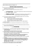
For your safety, please read user's manual thoroughly before operating.
Contact the nearest authorized service facility for examination, repair, or adjustment.
Please contact qualified service technician when you need maintenance.
Do not disassemble or repair by yourself!
Safety Instructions
Any maintenance and inspection shall be performed by the personnel having expertise concerned.
2005.5 LS Industrial Systems Co.,Ltd. All rights reserved.
www.lsis.biz
HEAD OFFICE
LS Tower 1026-6, Hogye-dong, Dongan-gu,
Anyang-si, Gyeonggi-do 431-848, Korea
Global Network
LS Industrial Systems (Middle East) FZE
Dalian LS Industrial Systems Co., Ltd.
Europe
+82-2-2034-4376 / [email protected]
Middle East
+82-2-2034-4901 / [email protected]
South West Asia
+82-2-2034-4645 / [email protected]
South East Asia
+82-2-2034-4707 / [email protected]
CIS
+82-2-2034-4913 / [email protected]
America
+82-2-2034-4377 / [email protected]
Dubai, U.A.E.
Address: LOB 19 JAFZA VIEW TOWER Room 205, Jebel Ali Freezone P.O. Box 114216, Dubai, United Arab Emirates
Tel: 971-4-886 5360 Fax: 971-4-886-5361 e-mail: [email protected]
Dalian, China
Address: No.15, Liaohexi 3-Road, Economic and Technical Development zone, Dalian 116600, China
Tel: 86-411-8273-7777 Fax: 86-411-8730-7560 e-mail: [email protected]
LS Industrial Systems (Wuxi) Co., Ltd.
Wuxi, China
Address: 102-A , National High & New Tech Industrial Development Area, Wuxi, Jiangsu, 214028, P.R.China
Tel: 86-510-8534-6666 Fax: 86-510-522-4078 e-mail: [email protected]
LS-VINA Industrial Systems Co., Ltd.
Hanoi, Vietnam
Address: Nguyen Khe - Dong Anh - Ha Noi - Viet Nam
Tel: 84-4-882-0222 Fax: 84-4-882-0220 e-mail: [email protected]
LS-VINA Industrial Systems Co., Ltd.
Hochiminh , Vietnam
Address: 41 Nguyen Thi Minh Khai Str. Yoco Bldg 4th Floor, Hochiminh City, Vietnam
Tel: 84-8-3822-7941 Fax: 84-8-3822-7942 e-mail: [email protected]
LS Industrial Systems Tokyo Office
Tokyo, Japan
Address: 16FL, Higashi-Kan, Akasaka Twin Tower 17-22, 2-chome, Akasaka, Minato-ku Tokyo 107-8470, Japan
Tel: 81-3-3582-9128 Fax: 81-3-3582-2667 e-mail: [email protected]
LS Industrial Systems Shanghai Office
Shanghai, China
Address: Room E-G, 12th Floor Huamin Empire Plaza, No.726, West Yan'an Road Shanghai 200050, P.R. China
Tel: 86-21-5237-9977 (609) Fax: 89-21-5237-7191 e-mail: [email protected]
LS Industrial Systems Beijing Office Beijing, China
Address: B-Tower 17FL.Beijing Global Trade Center B/D. No.36, BeiSanHuanDong-Lu, DongCheng-District,
Beijing 100013, P.R. China
Tel: 86-10-5825-6025,7 Fax: 86-10-5825-6026 e-mail: [email protected]
E.R.H.S.A.
Girardot 1368 - C1427AKD
C.A. de Buenos Aires - Argentina
Tel. (011) 4554-3232 www.erhsa.com
Specifications in this catalog are subject to change without notice due to
continuous product development and improvement.
2009. 03
LS Industrial Systems Guangzhou Office
Guangzhou, China
Address: Room 1403,14F,New Poly Tower,2 Zhongshan Liu Road,Guangzhou, P.R. China
Tel: 86-20-8326-6764 Fax: 86-20-8326-6287 e-mail: [email protected]
LS Industrial Systems Chengdu Office
Chengdu, China
Address: Room 1701 17Floor, huanminhanjun internationnal Building, No1 Fuxing Road Chengdu, 610041, P.R. China
Tel: 86-28-8670-3101 Fax: 86-28-8670-3203 e-mail: [email protected]
LS Industrial Systems Qingdao Office
Qingdao, China
Address: 7B40,Haixin Guangchang Shenye Building B, No.9, Shandong Road Qingdao 26600, P.R. China
Tel: 86-532-8501-6568 Fax: 86-532-583-3793 e-mail: [email protected]
Starvert iG5A(E)2005.05/(09)2009.03 PrintedinKorea STAFF