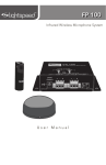
1
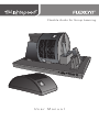
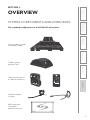
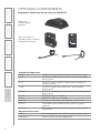
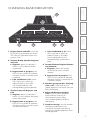
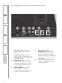
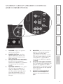
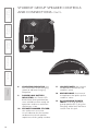
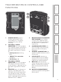
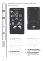
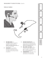
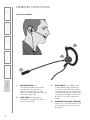
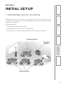
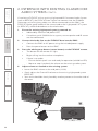
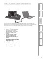
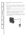
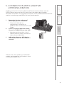
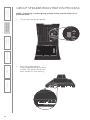
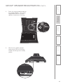
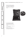
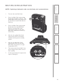
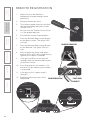
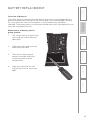
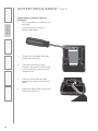
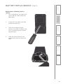
Flexible Audio for Group Learning
User Manual
TABLE OF CONTENTS
SECTION 1:
Overview
4
5
6
7
8
9
11
12
13
Important Safety Instructions
System Components and Unpacking
Optional Components
Charging Base Indicators
Charging Base Connections
Group Speaker Controls and Connections
Teacher Belt-pack Controls and Functions
Remote Control Functions and Indicators
Headset Functions
SECTION 2:
Initial Set-up
15
16
17
19
20
20
21
22
Determine Set-up Location
Connect the Base Station
Mount and Connect the Classroom Speaker
Charge the FLEXCAT Components
Power On All Components
Ensure All Components are Ready
Put the Headset on
Set Volume of Classroom Speaker
SECTION 3:
Daily Operation
23
Daily Operation Instructions
SECTION 4:
25
Additional Information 27
29
31
32
Tips and Tricks to Successful Use
Interface with Existing Classroom Audio
Multimedia Audio Integration
Connection with Assistive Listening Devices
Using Optional Speakers #5-6
SECTION 5:
33
Maintenance &
Troubleshooting
34
37
38
39
42
Registration of Replacement or Additional
Equipment
Group Speaker Registration Process
Belt-Pack Registration
Remote Registration
Battery Replacement
Troubleshooting
SECTION 6:
Warranty, Safety &
Specifications
45
46
47
Three-year Limited Warranty
Safety Warnings and Certifications
System Specifications
IMPORTANT SAFETY INSTRUCTIONS
1.
Read these instructions.
2.
Keep these instructions.
3.
Heed all warnings.
4.
Follow all instructions.
5.
Do not use the apparatus near
water.
6.
Clean only with dry cloth.
7.
Do not block any ventilation
openings. Install in accordance
with the manufacturer’s
instructions.
8.
Do not install near any heat
sources such as radiators,
heat registers, stoves, or
other apparatus (including
amplifiers) that produce heat.
9.
Do not defeat the safety
purpose of the polarized
or grounding-type plug.
A polarized plug has two
blades with one wider than
the other. A grounding- type
plug has two blades and a
third grounding prong. The
wide blade or the third prong
is provided for your safety. If
the provided plug does not
fit into your outlet, consult an
electrician for replacement of
the obsolete outlet.
10. Protect the power cord
from being walked on or
pinched particularly at plugs,
convenience receptacles, and
the point where they exit from
the apparatus.
11. Only use attachments/
accessories specified by the
manufacturer.
4
12. Use only with a cart, stand,
tripod, bracket or table
specified by the manufacturer,
or sold with the apparatus.
When a cart is used, use
caution when moving the cart/
apparatus combination to
avoid injury from tip-over.
13. Unplug this apparatus during
lightning storms or when
unused for long periods of
time.
14. Refer all servicing to qualified
service personnel. Servicing is
required when the apparatus
has been damaged in any way,
such as power-supply cord or
plug is damaged, liquid has
been spilled or objects have
fallen into the apparatus, the
apparatus has been exposed
to rain or moisture, does not
operate normally, or has been
dropped.
15. When the mains plug or
appliance coupler used as
the disconnect device, it shall
remain readily operable.
16. Please keep the unit in a good
ventilation environment.
OVERVIEW
SYSTEM COMPONENTS AND UNPACKING
4. Additional
Information
The standard configuration of the FLEXCAT will contain:
5. Maintenance &
Troubleshooting
6. Safety &
Specifications
SECTION 1:
Charging base station
with power supply
OFF
ON
REGISTER
LINK
BELT-PACKS
REGISTER
REMOTES
3. DaiIy Operation
AUDIO LINK
REGISTER
GROUP SPEAKERS
2. Initial Set-up
Student group
speakers (x4)
1
4
2
3
6
5
PO
WER
/ RE
AD
Y
1
2
TEAC
HER
Mute
Vol
Vol
1. Overview
Teacher belt-pack (1)
& Teacher remote (1)
Teacher headset
(2 types)
Wall-mounted
Classroom
Speaker with wire
5
5. Maintenance &
Troubleshooting
6. Safety &
Specifications
OPTIONAL COMPONENTS
Equipment which may be part of your FLEXCAT:
Additional
student group
speakers
Team teaching kit:
2nd belt-pack, headsets
and remote control
1
4
2
3
6
5
PO
WER
/ RE
AD
Y
1
Mute
Vol
Vol
4. Additional
Information
2
TEAC
2. Initial Set-up
3. DaiIy Operation
HER
Standard Components
FCCB
FCGS
FCTT
1. Overview
FCBP
FCHRC
FCOE
FCUE
NXQ-30
NH12V
NH2.4V
Optional Accessories
16VCC
MMC3535
6
FLEXCAT charging base station with power supply
FLEXCAT student group speaker with rechargeable
battery pack
FLEXCAT team-teacher kit (belt-pack, headset &
remote control)
FLEXCAT teacher belt-pack with rechargeable
battery pack
FLEXCAT handheld remote control with rechargeable
battery pack
FLEXCAT over-ear headset
FLEXCAT under-ear headset
Flat-panel classroom wall speaker with 30’ wire
12V NiMH rechargeable battery pack for group
speakers
2.4V NiMH rechargeable battery pack for belt-pack
and remote
DC charging cable for optional group speakers #5-6
3.5mm-3.5mm stereo audio cable
6. Safety &
Specifications
CHARGING BASE INDICATORS
5
AUDIO LINK
REGISTER
GROUP SPEAKERS
1
2
1. Power Switch and LED: turns the
FLEXCAT system power on or off.
The LED will glow blue when the
system is on.
2. Student Group Speaker Register
and Link
a.Register: press this button if
there is a new speaker to be
registered.
b. Registration in progress: this
LED will turn yellow to indicate
the base station is searching for
a speaker.
c. Link established (1-6): these
LEDs light up in green to
indicate there is an audio
link established with the
corresponding group speaker.
3. Teacher belt-pack Register and
Link
a.Register: press this button if
there is a new teacher belt-pack
to be registered.
b. Registration in progress: this
LED will turn yellow to indicate
the base station is searching for
a teacher belt-pack.
REGISTER
LINK
BELT-PACKS
3
REGISTER
REMOTES
4
c. Link established (1-2): these
LEDs light up in green to
indicate there is an audio
link established with the
corresponding teacher beltpack.
4. Teacher Remote Register Button
and Indicator
a.Register: press this button
to search for a new teacher
remote.
b. Registration in progress: this
LED will turn yellow to indicate
the base station is searching for
a teacher remote.
5. Student group speaker charging
slots (1-4): insert each of the
group speakers into these slots for
daily recharging.
3. DaiIy Operation
ON
2. Initial Set-up
OFF
1. Overview
6
4. Additional
Information
5. Maintenance &
Troubleshooting
7
6. Belt-pack/Remote charging
slots: insert the belt-pack(s)
and remote(s) into any of
these charging slots (they
are interchangeable) for daily
recharging.
7. Headset storage: set the teacher
headset(s) and excess wire
into these storage slots during
charging to keep equipment neat
and organized.
7
1. Overview
2. Initial Set-up
3. DaiIy Operation
4. Additional
Information
5. Maintenance &
Troubleshooting
6. Safety &
Specifications
CHARGING BASE CONNECTIONS
8
6
5
SPEAKER
VOLUME
SPEAKER
OUTPUT
4
3
OUT
IN
AUDIO
1.
DC Power input: Plug the
power supply (16V/2.0A) into
this jack.
2.
Charging outputs: these DC
charging output connections are
designed to charge 2 additional
desktop speakers.
3.
Audio input: plug a 3.5mm
cable from a computer or other
audio device to play that audio
to the whole class through the
classroom speaker.
4.
Audio output: sends whole
class instruction audio to
external classroom audio system
or Assistive Listening Device.
2
1
CHARGE OUT
16V/0.3A
DC POWER
16V/2.0A
5.
Classroom Speaker
Connection: speaker output
for connection to flat-panel
classroom speaker. Distributes
teacher and student audio to the
whole class when center button
is activated.
6.
Classroom Speaker Volume:
controls the volume level of the
classroom speaker.
2
REG
READY
REGISTER
3 4
ON
POWER
OFF
6
REG
READY
REGISTER
5
GROUP
#
4. Additional
Information
ON
POWER
OFF
5. Maintenance &
Troubleshooting
VOL
1
VOL
6. Safety &
Specifications
STUDENT GROUP SPEAKER CONTROLS
AND CONNECTIONS
1.
VOLUME: adjust the speaker
volume up or down.
2.
POWER SWITCH: turns the
speaker power on or off. The
power shuts off automatically
when charging.
3.
4.
5.
REGISTRATION IN PROGRESS:
this LED will turn yellow to
indicate the speaker is in process
of registering with the base
station.
REGISTER: press this button to
register a new group speaker.
The speaker comes preregistered with the base station.
This only needs to be activated
if the speaker is replaced for
service or an additional speaker
is added.
6.
SPEAKER “READY”: this green
LED will light to indicate it is
ready for operation. The link
will take several seconds to be
re-established each time it is
powered on or removed from
charger.
DESKTOP SPEAKER NUMBER:
this 7-segment LED indicates the
group # this speaker has been
registered to. This display should
match the sticker on the topside
of the speaker.
7.
BATTERY COMPARTMENT:
remove screw and open to
replace rechargeable battery
pack.
1. Overview
7
2. Initial Set-up
3. DaiIy Operation
GROUP
#
9
6. Safety &
Specifications
STUDENT GROUP SPEAKER CONTROLS
AND CONNECTIONS CONT’D
12
5. Maintenance &
Troubleshooting
11
10
4. Additional
Information
CHARGE
9
3. DaiIy Operation
8
POWER
Charge
16V/0.3A
1. Overview
2. Initial Set-up
13
8.
CHARGING INDICATOR: this
LED turns RED when charging,
green to indicate charging
complete.
9.
POWER/LOW BATTERY
INDICATOR: this Power LED
blinks blue when powered on,
turns solid blue when ready for
operation and turns red when
the battery is low.
10. SPEAKER NUMBER STICKER:
this sticker acts as a clear
visual indicator for the teacher
to determine which speaker
represents which group number.
10
11. LOUDSPEAKER: the internal
loudspeaker distributes the
teacher’s voice.
12. MICROPHONE: the internal
microphone that picks up the
students’ voice.
13. DC CHARGING/POWER
INPUT: to charge optional
group speaker #5-6, plug the
charging cable from the base
station into this jack.
6. Safety &
Specifications
TEACHER BELT-PACK CONTROLS AND
FUNCTIONS
8
1
7
2.
TEACHER 1 STATUS
INDICATOR: this multi-purpose
LED indicates power, low battery
and ready for operation for the
belt-pack registered as Teacher
#1.
TEACHER 2 STATUS
INDICATOR: this multi-purpose
LED follows the same function
as the Teacher 1 indicator for the
belt-pack registered as Teacher
#2.
4.
REGISTER: press this button to
register a new belt-pack. The
belt-pack comes pre-registered
with the base station. This only
needs to be activated if the beltpack is replaced for service or an
additional one is added.
4. Additional
Information
CH
3
ER
6
REGISTRATION IN PROGRESS
(NOT SHOWN): the Teacher
1 and 2 status indicator LEDs
will blink alternately to indicate
the belt-pack is in process of
registering.
6.
CHARGING INDICATOR: this
LED turns RED when charging,
green to indicate charging
complete.
7.
HEADSET CONNECTION: the
teacher headset connects to this
2.5mm jack.
8.
AUDIO INPUT: connect an
external device like an iPod or
computer to send multimedia
audio to any group speakers.
9.
BELT-CLIP: use this clip to
secure the belt-pack to a belt or
pocket. Alternatively, the beltpack can be placed inside the
pocket.
• Low battery: red
3.
TEA
5.
• Initial power on: blinking
blue
• “READY” for operation:
solid blue
Y
2
2
POWER SWITCH: powers
the belt-pack on/off. Press
up to power on. The power
automatically shuts off for
charging.
EAD
1
10
1.
R/ R
3. DaiIy Operation
WE
2. Initial Set-up
PO
1. Overview
9
5. Maintenance &
Troubleshooting
4
10. BATTERY COMPARTMENT:
remove to replace rechargeable
battery pack.
11
1
5. Maintenance &
Troubleshooting
6. Safety &
Specifications
REMOTE CONTROL FUNCTIONS AND
INDICATORS
1
4
2
2
3
6
4. Additional
Information
5
3. DaiIy Operation
3
4
Mute
Vol
7
6
2. Initial Set-up
5
Vol
CLASSROOM SPEAKER
SELECTION: press to select the
classroom speaker for whole
group instruction. The button
turns green when selected, red
when the teacher microphone is
muted.
2.
GROUP SPEAKER SELECTION
(1-6): press to select a specific
speaker. The button turns green
when addressing that group, red
when monitoring (listening only).
1. Overview
1.
3.
12
MICROPHONE MUTE
(MONITOR): press this button
to mute the microphone and
monitor the different groups.
4.
EARPIECE VOLUME: these
volume controls turn up and
down the earpiece volume of
the teacher headset, allowing
you to hear the student groups
at the appropriate volume level.
5.
CHARGING INDICATOR:
This LED turns RED when
charging and GREEN when fully
recharged.
6.
LOW BATTERY INDICATOR:
This LED turns RED when battery
is low.
7.
BATTERY COMPARTMENT:
remove screw and open to
replace rechargeable battery
pack
6. Safety &
Specifications
HEADSET FUNCTIONS CONT’D
4. Additional
Information
5. Maintenance &
Troubleshooting
Under-ear headset:
1
5
4
3. DaiIy Operation
2
1.
MICROPHONE: this
microphone boom should be
located near the mouth as
shown in the diagram. It can
rotate to be positioned either on
the left or right side.
2.
EAR PIECE: the ear piece
should be inserted into the
ear canal as pictured. It can be
swiveled to fit on either the left
or right ear.
3.
MICROPHONE MUTE: as an
alternate to the remote control,
you can press this button on the
headset to mute the microphone
(NOT RECOMMENDED).
4.
EAR PIECE VOLUME: as an
alternate to the remote control,
you can move this dial up or
down to adjust ear piece volume
(NOT RECOMMENDED).
5.
CONNECTOR: insert this 2.5mm
connector into the headset
connection on the belt-pack.
1. Overview
2. Initial Set-up
3
13
Over-ear headset:
4. Additional
Information
5. Maintenance &
Troubleshooting
6. Safety &
Specifications
HEADSET FUNCTIONS
3. DaiIy Operation
3
1. Overview
2. Initial Set-up
2
14
1
1.
MICROPHONE: this
microphone boom should be
located near the mouth as
shown in the diagram. It can
rotate to be positioned either on
the left or right side.
2.
EAR PIECE: the ear piece
should be inserted into the ear
canal as pictured.
3.
EAR HOOK: this rubber hook
is designed to be placed over
the ear. It can slide up or down
to adjust for ear size and can be
swiveled around the center post
to allow the headset to be worn
on the left or right side of the
head.
4.
CONNECTOR (NOT SHOWN):
insert this 2.5mm connector into
the headset connection on the
belt-pack.
6. Safety &
Specifications
SECTION 2:
INITIAL SET-UP
The FLEXCAT base station can be set up anywhere in the classroom, but it is best
suited to be in a location near the teachers desk and is highly accessible for both
teachers and students.
5. Maintenance &
Troubleshooting
1. DETERMINE SET-UP LOCATION
• Accessible for daily charging of all components
• Close proximity to audio source (computer) for multimedia integration
Charging Station
1. Overview
2. Initial Set-up
Classroom
Speaker
3. DaiIy Operation
• Close proximity to AC power outlet
4. Additional
Information
Key considerations:
Group Speakers
15
1.
Locate the power supply and
AC power cord. Connect the AC
power cord into the DC power
supply.
2.
Plug the AC power cord into an
electrical outlet.
3.
Insert the DC connector into the
“DC POWER INPUT” jack on the
base station.
4.
Switch the power to the ON
position.
4. Additional
Information
5. Maintenance &
Troubleshooting
6. Safety &
Specifications
2. CONNECT THE BASE STATION
1. Overview
2. Initial Set-up
3. DaiIy Operation
4
ON
OFF
ON
AUDIO LINK
REGISTER
GROUP SPEAKERS
16
2.
Hammer
Level (recommended)
Surface mounted wire raceway (recommended)
Select wall-mounting location:
One NXQ flat-panel classroom speaker will distribute sound throughout a
classroom of up to 1200 square feet (112 sqm) with ceiling heights of 9-12
feet (2.75 - 3.75m). The location of the speaker is important to ensure this
even sound distribution.
•
The speaker should hang at or near the center of the long wall in the
classroom (see figure 1).
•
It should be hung at a height of 7-8 ft (2.13 - 2.43m) in the classroom (see
figure1).
•
With those criteria in mind, we recommend locating as close as possible
to the FLEXCAT base station to minimize cable and raceway runs.
3.
Mount the speaker onto the wall:
•
The NXQ flat-panel classroom speaker is designed to be hung on a
wall just like a standard picture.
•
Using the hardware provided (for drywall) insert two wall hangers into
the wall with a hammer, approximately 6” apart. Use a level to ensure
they are at the same height.
•
Locate the coil of speaker wire. Connect one end of the wire to the
NXQ speaker. Press down the speaker tabs on the back of the speaker
and insert the red and black wires into the corresponding terminals.
•
Hang the speaker on the wall hangers, using the hanging wire on the
back in the same manner as hanging a picture.
•
Route the other end of the wire back to the FLEXCAT base station.
Secure the wire to the wall using surface raceway where required.
1. Overview
2. Initial Set-up
Classroom
Speaker
6. Safety &
Specifications
•
•
•
5. Maintenance &
Troubleshooting
Locate the following tools and supplies:
4. Additional
Information
1.
3. DaiIy Operation
3. MOUNT & CONNECT CLASSROOM
SPEAKER
17
6. Safety &
Specifications
4.
Connect the speaker wire to FLEXCAT base station:
•
Unplug the euro-block SPEAKER OUTPUT connector from the
FLEXCAT
•
Insert the two wires into the connector. The red (+) wire should be
inserted into the left side, black (-) into the right side.
•
Tighten the screw on top of the connector with small screwdriver to
secure.
•
Plug the euro-block connector back into the FLEXCAT and secure using the two side screws.
1. Overview
2. Initial Set-up
3. DaiIy Operation
4. Additional
Information
5. Maintenance &
Troubleshooting
3. MOUNT & CONNECT CLASSROOM
SPEAKER CONT’D
18
SPEAKER
VOLUME
SPEAKER
OUTPUT
IN
OUT
AUDIO
CHARGE OUT
16V/0.3A
DC POWER
16V/2.0A
Insert all four group speakers
into the charging cradle. The
charging LED will turn RED to
indicate normal charging. When
fully charged, it will turn GREEN.
2.
Insert the teacher belt-pack(s)
into the charging cradle. Any
of the four small slots are
compatible. The charging LED
will turn RED to indicate normal
charging. When fully charged, it
will turn GREEN.
3.
Insert the teacher remote(s) into
the charging cradle. Any of the
four small slots are compatible.
The charging LED will turn RED
to indicate normal charging.
When fully charged, it will turn
GREEN.
1. Overview
1.
2. Initial Set-up
3. DaiIy Operation
4. Additional
Information
5. Maintenance &
Troubleshooting
Prior to full operation, all system components should be fully charged (up to 8
hours) to ensure optimum performance.
6. Safety &
Specifications
4. CHARGE THE FLEXCAT COMPONENTS
19
6. Safety &
Specifications
5. Maintenance &
Troubleshooting
1.
DESKTOP SPEAKERS: Locate
the power switch on the bottom
of all four speakers. Switch to
the ON position. The station
number LED will light as will the
blue power on indicator.
2.
TEACHER BELT-PACK: Locate
the power switch on the side
of the unit. Switch to the ON
position. The blue teacher
indicator will flash for several
seconds and then turn solid to
indicate it is ready for use.
3.
TEACHER REMOTE: There
is no power switch on this
component, it stays ready for
operation.
1. Overview
2. Initial Set-up
3. DaiIy Operation
4. Additional
Information
5. POWER ON ALL COMPONENTS
20
6. ENSURE ALL COMPONENTS ARE READY
1.
DESKTOP SPEAKERS: The
amber colored LED on the
bottom of the desktop speaker
will light after a few seconds to
indicate it is ready for operation.
2.
TEACHER BELT-PACK: The
Teacher 1 or Teacher 2 LED will
turn solid blue to indicate it is
ready for operation.
3.
TEACHER REMOTE: Press a
speaker # button to test. If the
button lights, the remote is
ready.
1.
Determine which side of the
face you would like to wear
it on.
5. Maintenance &
Troubleshooting
Under Ear Headset: both
the ear piece and microphone
boom pivot to wear on either
side. Adjust as necessary.
UNDER-EAR HEADSET
3. DaiIy Operation
Place headset onto the ear
and adjust.
4. Additional
Information
Over Ear Headset: the ear
hook and microphone boom
can be rotated to wear on
either side. Adjust as necessary.
2.
Under Ear: slide the grey
rubber piece behind your ear
and place the ear piece into
the ear canal. Adjust so the
microphone boom is near the
mouth.
1. Overview
Connect the headset to the
belt-pack. Insert the 2.5mm
connector into the headset input
on the belt-pack.
2. Initial Set-up
Over Ear: place the hook over
the ear and insert the earpiece
into the ear canal. Adjust the
headset is needed so the
microphone boom is near the
mouth.
3.
6. Safety &
Specifications
7. PUT THE HEADSET ON
OVER-EAR HEADSET
21
6. Safety &
Specifications
The group speakers should be placed in the middle of four different student
groups or learning stations as follows:
•
Placed on a stable, flat surface
•
Within 3-6 feet of all students in that group
•
Top surface of the speaker should be clear with nothing set on top to ensure
optimum sound quality and microphone pickup.
2. Initial Set-up
3. DaiIy Operation
4. Additional
Information
5. Maintenance &
Troubleshooting
8. DETERMINE PLACEMENT LOCATION OF
THE GROUP SPEAKERS
9. SET APPROPRIATE VOLUME OF
CLASSROOM SPEAKER
The classroom speaker volume adjustment is preset to a nominal level (12:00).
Depending on the classroom, you may need to adjust up or down.
1.
Press the center button to turn on the classroom speaker.
2.
While speaking in a normal voice, fine tune the volume up or down.
1. Overview
Proper volume level is determined as follows:
• Your voice should be clearly heard
by another person on the other
side of the room.
• You should barely be able to hear
your own voice.
• There should not be any audio
“feedback” or squealing outside
of 2-3 feet (if there is, turn the
volume down slightly).
REMEMBER: This equipment
supplements the user’s voice
so they are able to speak in a
conversational tone. Having the
volume set too high will result in
feedback and listener fatigue.
22
SPEAKER
VOLUME
SPEAKER
OUTPUT
OUT
IN
AUDIO
CHARGE OUT
16V/0.3A
DC POWER
16V/2.0A
Remove the group speakers from the charger and place them on the
group tables.
•
The speakers will stay powered on while charging when the switch is
left in the on position.
•
Note the location of the speaker numbers.
Remove the belt-pack and headset and put them on.
•
The belt-pack will automatically power on when the switch is left in the
on position.
•
The blue LED will turn on after a few seconds to indicate the unit is
powered on and linked with the base station
•
The belt-pack can be worn anywhere that is comfortable for the
teacher. It can be clipped to a belt, to the outside of a pocket, or worn
inside a pocket.
•
Place the headset on, using either the under-ear or over-ear headset
provided, depending on your preference.
1. Overview
2.
2. Initial Set-up
3. DaiIy Operation
4. Additional
Information
1.
5. Maintenance &
Troubleshooting
DAILY OPERATION
INSTRUCTIONS
6. Safety &
Specifications
SECTION 3:
23
3.
Remove the remote and begin instruction. Use the remote to:
•
Address the whole class
•
Instruct small groups
•
Redirect small groups
•
Monitor (listen only) small groups
•
Activate student group sharing
•
Adjust earpiece volume
1
4
2
3
6
5
Mute
Vol
Vol
Using the remote:
1
Function
Whole Class
4 Instruction
2
Command
Press
center
button
Description
Activates classroom speaker to
distribute teachers voice to the
entire class.
Press #1-6
Activates a 2-way audio connection
to a small group. The teacher can
address and listen to that group
simultaneously.
Small Group
Monitoring
Press MUTE, then
#1-6
Mutes the teacher's microphone
while allowing the teacher to listen
in on group conversations. The
speaker # button will turn RED.
Student Group
Sharing
Press center
Allows one student group to
button, then press address all other students for
and hold #1-6
presentations and sharing. Both the
ALL and station # buttons will light.
Disconnect
Press activated
group # again
This disconnects the transmission
and turns any audio off. The LED for
the selected function will turn off.
Teacher ear
piece volume
Press Vol UP/
DOWN arrows.
Turns the volume to the teacher's
ear piece up or down. There is
an audible tone in the ear when
pressing.
3
5
6
Small Group
Instruction
Mute
1. Overview
2. Initial Set-up
3. DaiIy Operation
4. Additional
Information
5. Maintenance &
Troubleshooting
6. Safety &
Specifications
DAILY OPERATION CON’T
4.
Vol
Vol
Return the components to the base station for nightly recharging:
•
We recommend leaving the group speakers and belt-pack(s) in the ON
position, both components will charge as normal.
•
Place all components in their respective charging slots:
– Group Speakers: insert with charging contacts facing down.
– Remote(s) & Belt-pack(s): the four small slots are interchangeable
24
•
The charging LED’s will turn RED to indicate charging, green when fully
charged.
•
The units will fully charge overnight.
5. Maintenance &
Troubleshooting
ADDITIONAL
OPERATION
INFORMATION
6. Safety &
Specifications
SECTION 4:
Group speakers should be placed in the approximate center of the group
•
They can be placed on the center of a table or on the floor where the
students are sitting.
•
The microphone is designed to pick up students in a 360 degree radius, so
it also operates best when in the middle of a group.
Managing equipment and charging
•
Leave all components in the on position.
- When you place them on the charger, they will automatically power down
to charge.
- When you remove them from the charger to start the day, they will
automatically power back up.
•
Assign students to manage the charging of the group speakers.
- Have one assigned student remove it from the charger to start the day
and place it back on the charger at the end of the day.
3. DaiIy Operation
•
2. Initial Set-up
Determining optimum placement of the group speakers
4. Additional
Information
1. TIPS AND TRICKS TO SUCCESSFUL USE
•
This system is not designed to make the teachers voice louder, but to
distribute it appropriately so it is heard clearly by the selected group of
students or the whole class.
•
The group speakers are designed to be used independently, so turning the
volume up too loud can result in bleed-over to another group.
•
Typical volume levels at a group speaker are about half of the maximum
setting – approximately 12:00 on the dial.
•
It should be loud enough that students in the desired group hear you as
though you were speaking directly to them at a distance of 3 feet.
•
The classroom speaker should also be at a level that is not loud, but clear
throughout the whole room. Typically 12:00 on the speaker output volume
control is appropriate.
•
If connecting to existing audio system for whole group audio, adjust the
volume control on that amplifier appropriately - clear audio, not loud.
1. Overview
Determining proper group speaker volume levels
25
4. Additional
Information
5. Maintenance &
Troubleshooting
6. Safety &
Specifications
1. TIPS AND TRICKS TO SUCCESSFUL USE
CONT’D
Student group sharing
•
To activate this mode, be sure to start in whole group mode (center button
lighted), then press and hold the desired group # for about 2 seconds.
When activated, both center button and group # will be lit.
•
For optimum voice pickup, students will likely need to lean in toward the
group speaker to within about 24”.
Using the headset
•
Manipulate (curve) the headset microphone boom so that it is positioned as
close to your mouth as possible.
•
We recommend not using the mute and ear piece volume controls on the
under-ear headset cable as this can cause confusion in operation.
If your system is equipped with team-teaching
1. Overview
2. Initial Set-up
3. DaiIy Operation
•
26
Make sure to use the corresponding belt-pack and remote for Teacher 1 and
2, indicated as follows:
- Belt-pack: Teacher 1 or 2 LED is lighted
- Remote: Teacher 1 or 2 sticker on the remote (above barcode)
Ensure the existing amplifier is
powered on and connected to
speakers.
Connect the Audio Out on the
FLEXCAT base into an audio input
on the existing audio system
•
3.
The FLEXCAT base station has
a 3.5mm connection. Check
the existing audio system to
determine the required connector
type (typically 3.5mm, RCA or
1/4”).
Press the whole group button
(center button) on the FLEXCAT
remote.
•
•
•
The button on the remote will
light.
Begin talking into the teacher
microphone.
4. Additional
Information
2.
Validate audio from other sources
is being broadcast through this
system.
OUT
IN
AUDIO
CLASS 2 WIRING
3. DaiIy Operation
•
Whole Group
Mode
1
4
2
3
6
5
Mute
Vol
Vol
If there is no audio:
2. Initial Set-up
1.
6. Safety &
Specifications
FLEXCAT can interface with existing classroom audio systems, leveraging that
equipment and turning it into the whole group broadcast. When whole group
mode is selected on the remote, the teacher and students will be broadcast
through the speakers of the existing system.
5. Maintenance &
Troubleshooting
2. INTERFACE WITH EXISTING CLASSROOM
AUDIO SYTEMS
- Ensure the belt-pack is on and
ready for operation (solid blue
LED)
4.
1. Overview
- Move to step 4 to check the
volume on the existing audio
system.
Adjust volume as needed on the
existing system.
• While talking into the headset, you
should barely be able to hear your
own voice.
• Your voice should be clearly heard
by another person on the other side
of the room.
2
1
Audio Input Volume
27
6. Safety &
Specifications
5. Maintenance &
Troubleshooting
2. INTERFACE WITH EXISTING CLASSROOM
AUDIO SYTEMS CONT’D
If interfacing FLEXCAT with an existing Lightspeed IR Classroom Audio System
(such as REDCAT), the FLEXCAT base station can connect into the iR Media
Connector, minimizing long cable runs. When connected into the iRMC, the
FLEXCAT whole group mode will be transmitted to the Lightspeed CAT system
(ie. REDCAT), and then broadcast to the whole room.
1.
3. DaiIy Operation
4. Additional
Information
2.
3.
Ensure the existing Lightspeed sytem is powered on.
•
Indicated by a blue or red power LED.
•
If interfacing with 700/800 Series sytems, ensure speaker and IR sensor
are also connected.
Connect the Audio Out on the FLEXCAT base into the iRMC.
•
Connect the iRMC to AC power using the included power supply.
•
Press the power button on the iRMC.
Press the whole group button (center button) on the FLEXCAT remote.
•
The button on the remote will light.
•
Begin talking into the teacher microphone.
•
If there is no audio:
- Ensure the belt-pack is on and ready for operation (solid blue LED)
- Move to step 4 to check the volume on the existing audio system.
4.
Adjust volume as needed on the existing system.
• Slowly adjust the Channel B volume on the existing Lightspeed system
(REDCAT).
• Your voice should be clearly heard by another person on the other side of
the room.
1. Overview
2. Initial Set-up
• Leave the iRMC volume at the mid point (12:00)
OUT
IN
AUDIO
CH. B volume
CH A
PWR
CH B
(wireless transmission)
IR Media Connector
28
REDCAT
(or other Lightspeed IR Classroom Audio System)
Connect an audio cable from
your computer (or other
device) into the audio input
connection on the base
station.
2.
Play the audio file on the
computer, adjusting the
volume on the computer as
needed.
3.
Press the center button on the
remote to distribute that audio
to the whole class.
NOTE: the teacher’s voice will
also be broadcast to whichever
group the multimedia is sent
to. Press MUTE on the remote
if you only wish the children to
hear the audio source.
2. Initial Set-up
1.
1. Overview
The FLEXCAT base station has an audio input connection for integration with
other classroom technology. When connected, that audio source is amplified and
distributed through the classroom speaker when in Whole Group mode.
3. DaiIy Operation
4. Additional
Information
5. Maintenance &
Troubleshooting
6. Safety &
Specifications
3. MULTIMEDIA AUDIO INTEGRATION
29
CONT’D
4.
Quick connction + multimedia sharing with individual student groups
•
For a fast, temporary connection to a portable audio device like an (iPod,
MP3 player, etc.) connect the audio device into the audio input on the
teacher belt-pack.
•
Connecting to the belt-pack also allows the teacher to share that audio with
specific groups.
•
Play the audio file on the computer, adjusting the volume on the computer
as needed.
•
Select “GROUP # 1-6” on the teacher remote to direct that audio to a
specific group. Press the center button to share with the whole class.
NOTE: the teacher headset can remain plugged in and can operate
simultaneously to the selected group speaker(s).
TIP: if you have a team-teaching system (2 belt-packs and 2 remotes) you
can send audio to one group (using Teacher 2 belt-pack) while talking to
another group (make sure to use the corresponding Teacher 2 remote to
direct the multimedia.
1. Overview
2. Initial Set-up
3. DaiIy Operation
4. Additional
Information
5. Maintenance &
Troubleshooting
6. Safety &
Specifications
3. MULTIMEDIA AUDIO INTEGRATION
30
PO
WE
R/ R
EAD
Y
1
2
TEA
CH
ER
• Check with ALD device
manufacturer if uncertain as
products differ in connector size and
shape.
2.
Connect a patch cable from Audio
Out on the FLEXCAT base into ALD.
• Most devices have either a “mic”
input or auxiliary input. Use the mic
input whenever possible.
Adjust the volume on ALD device
until desired level for the student is
reached.
2. Initial Set-up
3.
OUT
IN
AUDIO
4. Additional
Information
Determine the size and type of
audio input jack on the device.
3. DaiIy Operation
1.
5. Maintenance &
Troubleshooting
Students with assistive listening devices (ALD) can connect directly into the
FLEXCAT base to ensure they can clearly hear the teacher during whole
classroom instruction*. During group instruction, the HI students benefit from the
teacher’s voice being amplified at the local group speaker.
6. Safety &
Specifications
5. CONNECTION WITH ASSISTIVE
LISTENING DEVICES
1. Overview
*Please note, when speaking to individual
student group speakers, the teacher’s voice
is not transmitted to ALD.
31
6. Safety &
Specifications
6. USING OPTIONAL SPEAKERS #5-6
4. Additional
Information
5. Maintenance &
Troubleshooting
Although the standard FLEXCAT includes 4 group speakers, it is can to operate
with up to 6 group speakers! The additional speakers can be purchased together
with the main system or can be added down the road.
1.
Operation
2.
Charging
•
If speakers #5-6 are purchased
together with the original
system, they will already be
paired together and operate just
as speakers #1-4 do.
•
Group speakers #5-6 charge via
cable connected to the base
station.
•
Connect the included charging
cable(s) to the CHARGING
OUTPUT jack(s) on the base
station.
•
Connect the other end of the
jack to the CHARGE input jack
on the group speaker.
•
The charging light on the group
speaker will turn RED to indicate
charging. It will turn GREEN to
indicate the unit is fully charged.
•
1. Overview
2. Initial Set-up
3. DaiIy Operation
•
32
To select the speakers, simply
press the #5-6 buttons on the
remote. (See Section 3 for daily
operation instructions).
If the speakers were purchased
at a separate time from the rest
of the system, they will need to
be linked to the base station.
Please refer to the Group
Speaker Registration Process in
section 5.
6. Safety &
Specifications
SECTION 5:
REGISTRATION OF REPLACEMENT OR
ADDITIONAL EQUIPMENT
In order for all system components to operate and communicate with one
another, they must be registered to the base station. When purchased as a
complete system, all components will be pre-registered and ready for use, so
there is no need to manually register anything.
•
Turn on the base station.
•
Remove the belt-pack(s) from the
charger and ensure they are powered
on.
•
Remove each group speaker from the
charger and ensure they are powered
on.
•
Wait for the “Ready” signal from
all components as indicated by the
following:
OFF
ON
AUDIO LINK
REGISTER
GROUP SPEAKERS
ON
PO
WE
– The belt-pack(s) will have
a solid blue Teacher 1/2
LED lighted.
R/ R
EAD
Y
1
2
TEA
CH
ER
– Each speaker will have a solid blue
power light and a green ready light
(on bottom).
VOL
– Press the #1-6 keys on a remote.
The base station LINK LEDs will
light for each speaker and each
belt-pack that is already registered.
ON
POWER
OFF
REG
LINK
REGISTER
– The link light for the speaker you
are adding should not be lit.
•
Proceed to the instructions for the
appropriate component
2. Initial Set-up
Start with all current and operational
FLEXCAT system components
powered down (in the charger or
switched OFF).
1. Overview
•
3. DaiIy Operation
In the event a component needs to be replaced or an additional component is
purchased down the road, it will need to be registered following the step by step
instructions below.
4. Additional
Information
5. Maintenance &
Troubleshooting
MAINTENANCE &
TROUBLESHOOTING
READY
STATION
#
33
6. Safety &
Specifications
GROUP SPEAKER REGISTRATION PROCESS
NOTE: if replacing a student group speaker, make sure the faulty unit is
powered down.
Turn on the new group speaker.
5. Maintenance &
Troubleshooting
1.
VOL
VOL
ON
POWER
OFF
ON
POWER
OFF
4. Additional
Information
REG
READY
REGISTER
REG
READY
REGISTER
GROUP
#
3. DaiIy Operation
GROUP
#
1. Overview
2. Initial Set-up
2.
Press the group speaker
Registration button on the base
station. The yellow LED on the
base station will start flashing.
OFF
ON
AUDIO LINK
REGISTER
GROUP SPEAKERS
OFF
ON
AUDIO LINK
REGISTER
GROUP SPEAKERS
34
REGISTER
LINK
BELT-PACKS
REGISTER
REMOTES
VOL
ON
POWER
OFF
VOL
ON
POWER
OFF
REG
READY
REGISTER
REG
READY
REGISTER
GROUP
#
Wait for the yellow speaker
registration LED on the Base
Station to change to a steady
yellow.
OFF
ON
AUDIO LINK
REGISTER
GROUP SPEAKERS
REGISTER
LINK
BELT-PACKS
REGISTER
REMOTES
1. Overview
4.
2. Initial Set-up
3. DaiIy Operation
GROUP
#
5. Maintenance &
Troubleshooting
Press the registration button on
the group speaker. The yellow
registration LED on the new
speaker should start flashing.
4. Additional
Information
3.
6. Safety &
Specifications
GROUP SPEAKER REGISTRATION CONT’D
OFF
ON
AUDIO LINK
REGISTER
GROUP SPEAKERS
REGISTER
BELT-P
35
5.
5. Maintenance &
Troubleshooting
6. Safety &
Specifications
GROUP SPEAKER REGISTRATION CONT’D
Wait for the yellow registration
LED on the new group speaker
to change to a steady yellow. A
new speaker ID number will be
shown on the seven segment
display.
VOL
VOL
4. Additional
Information
ON
POWER
OFF
REG
READY
REGISTER
ON
POWER
OFF
REG
READY
REGISTER
GROUP
#
1. Overview
2. Initial Set-up
3. DaiIy Operation
GROUP
#
36
6.
The registration has failed if
either of the registration LEDs
do not change to a steady
yellow and instead start to flash
rapidly.
7.
If the registration fails repeat the
steps 2 through 5.
8.
Repeat these steps if an
additional group speaker needs
to be added or replaced.
6. Safety &
Specifications
BELT-PACK REGISTRATION
NOTE: if replacing a belt-pack, make sure the faulty unit is powered down.
3
PO
WE
Press the Belt-Pack registration
button on the new Belt-Pack.
Both of the blue Belt-Pack
registration LEDs on the new
Belt-Pack should start flashing
alternately.
4.
Wait for the yellow Belt-Pack
registration LED on the Base
Station to change to a steady
yellow.
5.
Wait for the blue Belt-Pack
registration LEDs on the new
Belt-Pack to settle on a single
steady blue LED.
6.
The registration has failed if any
of the registration LEDs start to
flash rapidly.
7.
If the registration fails repeat the
steps 2 through 5.
AUDIO LINK
REGISTER
GROUP SPEAKERS
R/ R
EAD
Y
1
2
TEA
CH
ER
3. DaiIy Operation
3.
1
5. Maintenance &
Troubleshooting
Press the Belt-Pack registration
button on the Base Station. The
yellow Belt-Pack registration LED
on the Base Station should start
flashing.
4. Additional
Information
2.
OFF
ON
AUDIO LINK
REGISTER
GROUP SPEAKERS
2
REGISTER
LINK
BELT-PACKS
REGISTER
REMOTES
2. Initial Set-up
Turn on the new Belt-Pack.
4
REGISTER
LINK
BELT-PACKS
REGISTER
REMOTES
1. Overview
1.
37
2. Initial Set-up
3. DaiIy Operation
4. Additional
Information
5. Maintenance &
Troubleshooting
6. Safety &
Specifications
REMOTE REGISTRATION
1.
Make sure that the Remote is
adequately charged enough to be
operating.
2.
Remove the battery cover.
3.
The remote needs to be set to match
the corresponding belt-pack, either
Teacher 1 or 2.
4.
Be sure that the Teacher Select switch
is in the proper position.
5.
Ensure Base Station is powered on.
6.
Press the Remote Registration button
on the Base Station. The yellow LED
will light.
7.
Press the Remote Registration button
on the Remote. The green LED will
light.
8.
Wait for both the yellow and green
pairing LEDs to turn off simultaneously,
typically after about 5 seconds.
9.
If the pairing LEDs turn off after 30
seconds then the Remote did not pair
to the Base Station.
2
INSIDE REMOTE
10. Press #1 button on the remote – the
button will light indicating the remote
is registered.
6
TEACH2
11. If the pairing fails, repeat steps 5
through 7.
REGISTRATION
TEACHER
SELECT
1. Overview
12. Replace the battery cover when
completed.
TEACH1
OFF
ON
AUDIO LINK
REGISTER
GROUP SPEAKERS
4
5
AUDIO LINK
GROUP SPEAKERS
REGISTER
LINK
BELT-PACKS
OFF
ON
AUDIO LINK
REGISTER
GROUP SPEAKERS
38
REGISTER
LINK
BELT-PACKS
REGISTER
REMOTES
REGISTER
REMOTES
Overview of batteries
The group speaker, teacher belt-pack and remote contain rechargeable battery
packs that require daily charging. The battery packs are covered under warranty
for 1-year but have a useful life of about 2+ years before they should be
replaced. The battery packs must be purchased directly from Lightspeed, but can
easily be installed by the user.
Replacement of battery pack in
group speaker
3.
Take the new battery pack,
connect the cable and insert
the battery pack into the
compartment.
4.
Slide the cover back on and
tighten the screw to secure the
door.
REG
READY
REGISTER
4. Additional
Information
ON
POWER
OFF
GROUP
#
3. DaiIy Operation
Slide the battery pack out and
disconnect the cable.
VOL
2. Initial Set-up
2.
Use a screw-driver to remove the
screw and the slide the battery
door open.
1. Overview
1.
5. Maintenance &
Troubleshooting
6. Safety &
Specifications
BATTERY REPLACEMENT
39
Replacement of battery pack in
belt-pack
1.
Use a screwdriver to remove the
belt-clip.
2.
Unscrew and the slide the
battery door open.
3.
Disconnect the cable and slide
the battery pack out.
4.
Take the new battery pack,
connect the cable as shown and
insert the battery pack into the
compartment.
5.
Slide the cover back on and
tighten the screw to secure the
door.
6.
Replace the belt-clip and tighten
the screw to secure.
1. Overview
2. Initial Set-up
3. DaiIy Operation
4. Additional
Information
5. Maintenance &
Troubleshooting
6. Safety &
Specifications
BATTERY REPLACEMENT CONT’D
40
3.
Take the new battery pack,
connect the cable as shown and
insert the battery pack into the
compartment.
4.
Slide the cover back on and
tighten the screw to secure the
door.
5. Maintenance &
Troubleshooting
Disconnect the cable and slide
the battery pack out.
4. Additional
Information
2.
3. DaiIy Operation
Use a screwdriver to remove the
screw and the slide the battery
door open.
2. Initial Set-up
1.
1. Overview
Replacement of battery pack in
remote
6. Safety &
Specifications
BATTERY REPLACEMENT CONT’D
41
6. Safety &
Specifications
5. Maintenance &
Troubleshooting
4. Additional
Information
TROUBLESHOOTING
Note: Most problems are directly related to low battery power. Please run
through the “Battery Check” items first. For remaining troubleshooting, use
known good, fully-charged batteries.
PROBLEM: most problems are related to low battery power.
SOLUTION: check the batteries and ensure proper charging.
• Confirm batteries are properly charged each night.
• When placing a component in a charger, ensure the RED charging LED turns
on. The GREEN charging light will turn on when a full charge is reached.
• Regardless of battery life, the RED light will turn on for 20-30 minutes to check
status. When battery is full, the light will turn GREEN at some time after that.
• Fully charged batteries will operate properly throughout a full school day for
a period of at least 1-2 years. If the batteries are older, they likely need to be
replaced.
3. DaiIy Operation
PROBLEM: No audio from group speaker.
SOLUTION: follow these steps to isolate and eliminate the problem.
• Ensure group speaker power is on.
- Turn the speaker on.
• Ensure headset is properly connected into the belt-pack
2. Initial Set-up
• Ensure the mute button on the remote is not turned on. The mute button
should be un-lighted and the GROUP # button selected should be green.
• Ensure the group speaker volume is set to a nominal level. If it is turned all the
way down, there will be no audio.
• Ensure group speaker is on and ready for use as indicated by a solid blue
power LED.
- Try turning the speaker off, then on again and wait up to 30 seconds for it
to properly link.
1. Overview
- When selected, a green LED on the base station for that group # will light.
• Ensure teacher belt-pack is on and ready for use as indicated by a solid blue
light.
- Turn the belt-pack on and wait up to 30 seconds for it to properly link.
- When the light is solid blue on the belt-pack there should also be a solid
green LED on the base station indicating the remote (Teacher 1 or 2) is
linked up and ready for use.
• Ensure teacher remote is properly registered.
- Press an operating GROUP # button. The green LED should light.
- If it doesn’t light, make sure the belt-pack and group speaker are both
“READY.”
- Ensure the batteries are fully charged. If the RED battery low LED is on, it
can experience intermittent operation.
42
PROBLEM: Remote does not light or activate any group speakers
6. Safety &
Specifications
TROUBLESHOOTING CONT’D
SOLUTION:
• Try pressing the MUTE button.
- If this button lights, the remote has a battery charge.
- If this button doesn’t light, the battery is dead.
• Ensure the base station is powered on.
5. Maintenance &
Troubleshooting
• Ensure the batteries have a charge. They should be charged nightly.
- “READY” for operation is indicated by a solid blue LED on the belt-pack
and group speaker(s).
- Once verified, try pressing that GROUP # button on the remote. This will
activate any speaker and any microphone that is linked up.
4. Additional
Information
• Ensure at least one group speaker and at least one belt-pack are “READY” for
operation.
- Try using the second remote to verify.
- If you are still unsure, open the remote’s battery door and observe the
position of the Teacher 1/Teacher 2 switch.
• It is possible the remote is not properly registered to work with the base
station. Please refer to the registration process to reconnect.
PROBLEM: Belt-pack does not indicate a “READY” signal
SOLUTION:
2. Initial Set-up
- The belt-pack has an LED indicator for Teacher 1/2. The remote has the
indication on the barcode sticker on the back of the unit.
3. DaiIy Operation
• If using a team teaching configuration, ensure the remote and belt-pack are
matching (Teacher 1 with Teacher 1).
• Ensure the batteries have a charge. They should be charged nightly.
• Ensure the base station is turned on. If the base station is power off, the beltpack has nothing to link to.
• Power the unit off, then on again after a few seconds. Wait for up to 30
seconds for the blue LED to turn solid, indicating READY for operation.
1. Overview
• Ensure the power switch is turned on. Once turned on, the LED should begin
blinking.
• If no READY signal is indicated, it is possible the belt-pack is not properly
registered to work with the base station. Please refer to the registration
process to reconnect.
43
6. Safety &
Specifications
TROUBLESHOOTING CONT’D
PROBLEM: Group speaker does not indicate a “READY” signal
SOLUTION:
1. Overview
2. Initial Set-up
3. DaiIy Operation
4. Additional
Information
5. Maintenance &
Troubleshooting
• Ensure the batteries have a charge. They should be charged nightly.
44
• Ensure the power switch is turned on. Once turned on, the blue Power LED on
top of the should begin blinking.
• Ensure the base station is turned on. If the base station is power off, the group
speaker has nothing to link to.
• Power the unit off, then on again after a few seconds. Wait for up to 30
seconds for the blue LED to turn solid, indicating READY for operation.
• If no READY signal is indicated, it is possible the group speaker is not properly
registered to work with the base station. Please refer to the registration
process to reconnect.
• Check 7-segment display on bottom of unit. If the display is blank or the
number is incorrect, there is a registration error. Please refer to the registration
process to reconnect.
1. Warranty on primary components including: base station, group speakers,
belt-pack and remote is THREE (3) YEARS.
2. Warranty on headset microphones and Lightspeed NiMH rechargeable
battery packs is one (1) year.
3. Prepaid shipping label provided by Lightspeed for warranty repairs within the
U.S. Customers outside the U.S. should refer to the Lightspeed website (
www.lightspeed-tek.com) for warranty repair instructions.
4. Warranty does not extend to finish, appearance items, or malfunctions due
to abuse or operation other than specified conditions, nor does it extend to
incidental or consequential damages. Repair by other than Lightspeed or its
authorized service agencies will void this warranty. Information on authorized
service agencies is available from Lightspeed Technologies, Inc.
5. Maintenance &
Troubleshooting
4. Additional
Information
Lightspeed’s Warranty Exchange Program applies to FLEXCAT systems within
the three (3) year warranty period. If any system component has an issue that
requires service, a refurbished replacement will immediately be sent to the
customer to minimize downtime. Customers will receive the exchange product(s)
or component(s) within 2-3 days. A prepaid return label will be included with
exchanged products so original malfunctioning equipment can be returned to
Lightspeed. Any exchanged equipment will remain covered under the original
three (3) year warranty.
3. DaiIy Operation
Lightspeed’s FLEXCAT Group Audio System is covered under warranty against
malfunction due to defects in materials and workmanship for a period of THREE
(3) YEARS, beginning at the date of the purchase invoice. If such malfunction
occurs, the product will be repaired or replaced (at Lightspeed’s option) without
charge during the warranty period.
2. Initial Set-up
THREE-YEAR LIMITED WARRANTY
1. Overview
WARRANTY, SAFETY &
SPECIFICATIONS
6. Safety &
Specifications
SECTION 6:
Our Service Department (800.732.8999, 5 a.m. – 5 p.m., PST) will handle all your
repair/replacement needs.
45
!
5. Maintenance &
Troubleshooting
6. Safety &
Specifications
SAFETY WARNINGS AND CERTIFICATIONS
CERTIFICATIONS
4. Additional
Information
Lightspeed Technologies launched a formal product recycle
program in Europe that complies with the European Union
Directive 2002/96/EC on Waste Electrical and Electronic
Equipment (“WEEE Directive”). Please visit our website at
www.Lightspeed-tek.com for more information.
1. Overview
2. Initial Set-up
3. DaiIy Operation
This product is manufactured using lead-free processes and is
free of other materials harmful to the environment. It conforms
to the most stringent new European guidelines for consumer
products (RoHS).
This device complies with part 15 of the FCC Rules. Operation is subject to the following
two conditions: (1) This device may not cause harmful interference, and (2) this device
must accept any interference received, including interference that may cause undesired
operation.
WARNING: Changes or modifications to this equipment not expressly approved by the
party responsible for compliance could void the user’s authority to operate the equipment.
NOTE: This equipment has been tested and found to comply withthe limits for a Class B
digital device, pursuant to Part 15 of the FCC Rules. These limits are designed to provide
reasonable protection against harmful interference in a residential installation. This
equipment generates, uses and can radiate radio frequency energy and, if not installed
and used in accordance with the instructions, may cause harmful interference to radio
communications.
However, there is no guarantee that interference will not occur in a particular installation. If
this equipment does cause harmful interference to radio or television reception, which can
be determined by turning the equipment off and on, the user is encouraged to try to correct
the interference by one or more of the following measures:
•
Reorient or relocate the receiving antenna.
•
Increase the separation between the equipment and receiver.
•
Connect the equipment into an outlet on a circuit different from that to which the
receiver is connected.
•
Consult the dealer or an experienced radio/TV technician for help.
CAUTION: To maintain the compliance with the FCC’s RF exposure guideline, place the
FLEXCAT Charging Base and FLEXCAT Student Group Speaker at least 20 cm from nearby
persons.
For body worn operation, the FLEXCAT belt-pack has been tested and meets the FCC RF
exposure guidelines when used with the Lightspeed accessories supplied or designated for
this product. Use of other accessories may not ensure compliance with FCC RF exposure
guidelines.
46
Audio Output:
3.5mm
Speaker Output:
2-pin euro-block (12 W RMS)
Wireless communication:
1.9 GHz wideband for audio
connections; RF4CE for control
signals
6 LED for link to group speakers
1-6; 2 LED for link to teacher beltpacks 1-2
push button for speaker(s), beltpack(s), and remote(s)
15.75” x 12” x 9.2”
DC Charge out:
Audio Link indicators:
Device Registration:
Dimensions (L x W x H):
GROUP SPEAKERS (1-6)
Battery Power:
12V NiMH battery pack
Audio output power:
5 Watts per speaker
Integrated Speaker:
2” balanced mode radiator (BMR)
Integrated Microphone:
omni-directional electret
Wireless communication:
1.9 GHz
Cradle charging:
2 contacts for cradle charging
DC charging input:
16V / 0.3A for alternate charging
cable
push button and LED for registration with base station
8.5” x 5.0” x 3.5”
Registration:
Dimensions (L x W x H):
TEACHER BELT-PACK (1-2):
Battery Power:
2.5V NiMH battery pack
Cradle charging:
2 contacts for cradle charging
Wireless communication:
1.9 GHz
Headset Input:
2.5mm TRS
Audio Input:
3.5mm stereo
Power:
on/off switch
Registration:
push button and LED for registration with base station
2.75” x 2.0” x 1.0”
Dimensions (L x W x H):
5. Maintenance &
Troubleshooting
Audio Input:
1-4 group speakers; 1-2 teacher
belt-packs; 1-2 handheld remotes
16V / 0.3A for 1-2 additional
group speakers
3.5mm stereo
4. Additional
Information
Cradle Charging:
3. DaiIy Operation
16V / 2.0A
2. Initial Set-up
DC Power Input:
1. Overview
BASE STATION
6. Safety &
Specifications
SYSTEM SPECIFICATIONS
47
SYSTEM SPECIFICATIONS CONT’D
HANDHELD REMOTE (1-2)
Battery Power:
2.5V NiMH battery pack
Cradle charging:
2 contacts for cradle charging
Wireless communication:
RF4CE
Controls:
Group speaker selection 1-6;
Microphone mute; Earpiece
volume
push button and LED for
registration with base station
4.25” x 2.0” x 1.0”
Registration:
Dimensions (L x W x H):
UNDER EAR HEADSET
Description:
Connector:
under-the-ear headset with boom
microphone and in ear piece
2.5mm
Microphone:
uni-directional boom microphone
Controls:
microphone mute and earpiece
volume up/down
OVER EAR HEADSET
Description:
48
Connector:
over-the-ear headset with boom
microphone and in ear piece
2.5mm
Microphone:
uni-directional boom microphone
Controls:
none on microphone
49
50
51
L IGHTSPEED TECHNOL OG I E S
1 1509 SW HERM AN R O A D / TUA L ATIN , O R 9 7 0 6 2
T OLL FREE: 800.73 2 .8 9 9 9 / PHO N E : 5 0 3 .6 8 4 .5 5 3 8 / FAX : 503. 684. 3197
LI GHTS PEED-TEK.CO M
MN0451US01-2


![User Manual PS 430 [ASL]](http://vs1.manualzilla.com/store/data/005676322_1-235f4942ab78942bc49f054c2ec420ac-150x150.png)