1
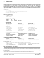
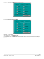
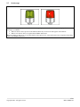
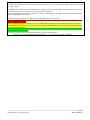
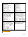
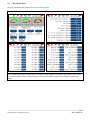
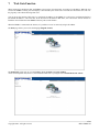
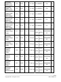
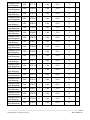
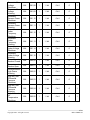
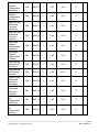
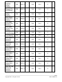
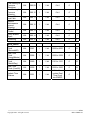
ENGINE MONITORING REMOTE PANEL (EMRP3.2, EMRP3.3) INSTALLATION AND OPERATION MANUAL Copyright 2009 – All right reserved. EMCP3, Cat® and Caterpillar® are registered trademarks of Caterpillar Inc. EMRP3 is not associated with or sponsored by Caterpillar® or Caterpillar’s® subsidiary Perkins. December 2011 MNA-EMRP3-04 Copyright 2009 – All right reserved. MNA-EMRP3-04 Table of Contents 1. Introduction .......................................................................................................................................................................... 1 2. Installation ............................................................................................................................................................................ 2 2.1 2.2 2.3 2.4 2.5 2.6 2.7 2.8 2.9 2.10 Basic Connection Block Diagram .............................................................................................................................. 2 Complete installation with the "Web Gate" function connection ............................................................................... 3 Installation on a cabinet using screw fasteners........................................................................................................... 4 Connecting the Power Cord ....................................................................................................................................... 8 Cable Connector RJ45 ................................................................................................................................................ 9 Setting the Communication Port of the EMCP3 ...................................................................................................... 10 Configuring the Ethernet to RS-485 converter ......................................................................................................... 10 Setting the communication port of the EMRP3........................................................................................................ 11 Configure the "Web Gate" function ......................................................................................................................... 13 RS485 (COM1) port connection .............................................................................................................................. 13 3. Configuration of the Controller ........................................................................................................................................ 15 4. Setting the date and time ................................................................................................................................................... 16 5. Page overview ..................................................................................................................................................................... 17 5.1 5.2 5.3 5.4 5.5 5.6 5.7 5.8 5.9 5.10 5.11 Data synchronization and communication losses ..................................................................................................... 17 Main Menu ............................................................................................................................................................... 18 Navigation Bar ......................................................................................................................................................... 19 Status Generator ....................................................................................................................................................... 20 Stroboscope .............................................................................................................................................................. 21 Panel of Events ......................................................................................................................................................... 22 Annunciator .............................................................................................................................................................. 24 Electrical Data .......................................................................................................................................................... 26 Mechanical Data....................................................................................................................................................... 27 Inputs and Outputs ................................................................................................................................................... 28 Metric / Imperial, Choice of Languages ................................................................................................................... 30 6. Changing the mode of operation of the generator........................................................................................................... 31 7. Web Gate Function ............................................................................................................................................................ 33 8. Modbus exchange table ..................................................................................................................................................... 35 9. Update the EMRP3 ............................................................................................................................................................ 57 10. Features............................................................................................................................................................................... 58 11. Models Available ................................................................................................................................................................ 59 12. References ........................................................................................................................................................................... 59 Copyright 2009 – All right reserved. MNA-EMRP3-04 Table of Figures Figure 1: Basic installation ............................................................................................................................................................ 2 Figure 2: Complete Installation...................................................................................................................................................... 3 Figure 3: Dimensions of the touchscreen ....................................................................................................................................... 4 Figure 4 : Dimensions of the entire touchscreen ............................................................................................................................ 5 Figure 5 : Drilling for fixing the touchscreen ................................................................................................................................ 6 Figure 6 : Installation of the touchscreen ....................................................................................................................................... 6 Figure 7 : Inserting the module behind the touchscreen ................................................................................................................ 7 Figure 8 : Remove the rear module of the touchscreen .................................................................................................................. 7 Figure 9: Power connector ............................................................................................................................................................. 8 Figure 10 : Connecting the power cable to the touchscreen........................................................................................................... 8 Figure 11 : Connector Ethernet RJ45 ............................................................................................................................................. 9 Figure 12 : Connector RJ45 for communication RS485 ................................................................................................................ 9 Copyright 2009 – All right reserved. MNA-EMRP3-04 1. Introduction The EMRP3 display panel allows the user to remotely monitor the data (electrical, mechanical and events tables) measured by an EMCP3 generator controller and its optional modules. It also allows him to easily access data and perform a remote control of your generator with a 5.7" high visibility TFT 65 536 colors touch screen. The built-in "Web Gate" function allows independent access to the EMRP3 with a simple Internet browser no matter where the user is located in the world. The EMRP3 module also has a Modbus slave communication port allowing the user to access the Modbus register grouped into contiguous register. CONTROLS Auto/Start/Stop; Time/date modification and synchronization with the EMCP3 controller; 12 warning/faults/customizable events. DIGITAL INDICATION Languages Available : English French Units Indications Available : Temperature : Celsius Fahrenheit Pressure : kPA PSI Volume : Liter US Gallon UK Gallon Generator Data: AC voltage (VAC) Current (A) Frequency (Hz) Power factor kW hour exported kVar hour exported Engine Data : Engine revolution Hours of operation Fuel temperature Exhaust temperature Oil temperature Oil pressure Coolant temperature Battery voltage Available Only With EMRP3.3 Version : Fuel level Exhaust temperature Fuel pressure Intake manifold air temperature Instantaneous fuel consumption Cylinder temperature Total fuel consumption Battery voltage Real power (kW) Apparent power (kVA) Reactive power (kVAr) Genset operating mode Service maintenance interval Crank attempt counter Successful start counter Turbo pressure Atmospheric pressure Generator winding temperature Generator bearing temperature WARNING/SHUTDOWNS INDICATION Overcrank Low coolant temperature High coolant temperature Overspeed High battery voltage Low battery voltage High fuel pressure Fuel filter restriction High intake manifold air temperature EVENTS TABLES Display the 20 latest events, warnings or faults for the following gensets equipments : EMCP3 controller 2 X Thermocouples module Automatic voltage regulator (CDVR) Engine control module (ECM) 2 X Inputs/outputs module RTD module INPUTS/OUTPUTS OF THE EMCP3 1 When an internet connection is available. * All of the above data are displayed when available in the EMCP3 controller, depending on the model of the generator installed options and optional modules installed on the generator (refer to the generator manufacturer for details) * EMRP3.X855TT and EMRP3.X855TR models require a converter (Ethernet – RS-485) to communicate with the EMCP3 and an Ethernet switch for using the "Web Gate" function. * Use of the EMRP3 name as well as its software content are protected by the copyright law, copyright 2009 – All rights reserved. Copyright 2009 – All right reserved. 1/59 MNA-EMRP3-04 2. Installation The installation of the EMRP3 requires an Ethernet to RS-485 converter. The converter needs to have a data transfer rate of 38400 bps. In order to use the "Web Gate" function, the user should install a 3 ports switch. Moreover, a stable supply of 24VDC needs to be available. 2.1 Basic Connection Block Diagram Figure 1: Basic installation If the EMRP3 is directly supplied by the batteries of the generator set, add a voltage regulator 24VDC/24VDC and that can regulate the exit voltage at 24VDC when the generator starts. The addition of the voltage regulator will avoid the restart of the EMRP3 when the generator starts. The Ethernet link must be made with a Category 5e twisted pair cable. Copyright 2009 – All right reserved. 2/59 MNA-EMRP3-04 2.2 Complete installation with the "Web Gate" function connection Figure 2: Complete Installation If the EMRP3 is directly supplied by the batteries of the generator set, add a voltage regulator 24VDC/24VDC and that can regulate the exit voltage at 24VDC when the generator starts. The addition of the voltage regulator will avoid the restart of the EMRP3 when the generator starts. The Ethernet links must be made with standard Category 5e cables. Copyright 2009 – All right reserved. 3/59 MNA-EMRP3-04 2.3 Installation on a cabinet using screw fasteners Figure 3: Dimensions of the touchscreen Copyright 2009 – All right reserved. 4/59 MNA-EMRP3-04 Figure 4 : Dimensions of the entire touchscreen Copyright 2009 – All right reserved. 5/59 MNA-EMRP3-04 Figure 5 : Drilling for fixing the touchscreen Figure 6 : Installation of the touchscreen Copyright 2009 – All right reserved. 6/59 MNA-EMRP3-04 Figure 7 : Inserting the module behind the touchscreen Figure 8 : Remove the rear module of the touchscreen Copyright 2009 – All right reserved. 7/59 MNA-EMRP3-04 2.4 Connecting the Power Cord Figure 9: Power connector The following table describes the different steps in order to connect the power connector: Figure 10 : Connecting the power cable to the touchscreen Copyright 2009 – All right reserved. 8/59 MNA-EMRP3-04 2.5 Cable Connector RJ45 The following illustrations show the location of the cable connectors RJ45: Figure 11 : Connector Ethernet RJ45 Figure 12 : Connector RJ45 for communication RS485 Copyright 2009 – All right reserved. 9/59 MNA-EMRP3-04 2.6 Setting the Communication Port of the EMCP3 The EMCP3 communication port has to be configured with the same parameters as the Ethernet to RS-485 converter. In order for the EMRP3 to work to its full capacity it is preferable to adjust the communication parameters of the link RS-485 (Modbus RTU) at a speed of 38400 baud. In order to configure the EMCP3 from the main menu, the user has to go to the following section: -Configure -Setpoints -Network -DataLink – SCADA Subsequently, the user must adjust the communication parameters below. The settings below enable optimum use of EMRP3. Parameters Baud Rate and Parity must be configured with the same values than the converter Ethernet to RS-485. Baud Rate: 38400 bauds Parity: None Slave Address: 1 Connect Timeout Interval: 30.0 sec RS-485 Bias Resistor: Disable 2.7 Configuring the Ethernet to RS-485 converter Converter Ethernet RS-485 must be configured as follows: Baud Rate: 38400 baud Parity: None Address IP: 192.168.0.104 The parameters of the IP address may differ in the integration of EMRP3 in a network. It must, however, change the settings in the EMRP3 under Section 2.8 if the modules are integrated into an existing network. Copyright 2009 – All right reserved. 10/59 MNA-EMRP3-04 2.8 Setting the communication port of the EMRP3 WARNING! The communication port of the EMRP3 is already configured at the factory for optimum use. It should not be changed unless the module integration in a network. To configure the communication port EMRP3, press on Screen settings in the main menu. The EMRP3 asks for a password to the user. Enter the username and password as follows: Name : admin Password : emrp When completed, press the icon to validate your password. Then click the icon: To exit the password menu and return to the main menu. To exit the password menu and return to the previous page. When the password is validated, return to the Screen settings of the main menu screen and the next page will appear. Press the icon HMI panel adjustment and the next page will appear. Copyright 2009 – All right reserved. 11/59 MNA-EMRP3-04 To edit the communications settings click Offline. The Network page allows you to set the network configuration of the EMRP3. The default settings are: Adresse IP : 192.168.0.100 Subnet Mask : 255.255.255.0 Gateway : 192.168.0.1 The user can modify the settings above to integrate the module EMRP3 to its network. The configuration of the communication with the Ethernet to RS-485 converter can be changed in section Gateway IP address. Copyright 2009 – All right reserved. 12/59 MNA-EMRP3-04 By default the devices are configured using the IP address: 192.168.0.104. 2.9 Configure the "Web Gate" function The configuration of the "Web Gate" function is done directly when setting the IP address of EMRP3. The default IP address of the "Web Gate" function is: 192.168.0.100. Caution: When using the "Web Gate" function, the communication port 6000 of your network must be unlocked to allow the user to access the contained of EMRP3. For more details, check with your network administrator. 2.10 RS485 (COM1) port connection The RS485 (COM1) is available for modbus data reading on the EMRP3.2855TR and EMRP3.3855TR modbus RTU slave version only. The diagram below shows connection to be made to connect the RS485 port. The RS485 port configuration is as follows : Baud Rate : 38400 baud Parity : None Slave Adress : 1 To change the configuration of the RS485 port press the icon Screen settings page will appear. Copyright 2009 – All right reserved. in the main menu screen and the next 13/59 MNA-EMRP3-04 Press the icon HMI panel adjustment and the next page will appear. To edit the communications settings click Offline. Subsequently, press IO Manager. A new page will appear, press Equipment Config. Select from the drop down menu ModbusSlave equipment and make changes to the communications port 485 depending on your setup. Copyright 2009 – All right reserved. 14/59 MNA-EMRP3-04 3. Configuration of the Controller From the main menu, press Generator Status access the configuration controller. . When the Generator Status page appears, press the right arrow to The controller configuration page will display the data configured in the EMCP3. The configuration of the controller must be kept updated when a technician makes some adjustments in the EMCP3. To maintain the configuration updated, click Data Synchro to synchronize the configuration of the EMCP3 in the EMRP3. The configuration of the controller is used by the EMRP3 to adjust the analog gauges. Provides access to configuration functions and control of the screen. Enter the username and password as follows: Name : admin Password : emrp Enables the user to secure the screen and limit access to functions and configuration control of the screen. Copyright 2009 – All right reserved. Enables the user to reset the Default Values (factory) of the EMRP 3 (text of the custom events). Synchronizes the configuration of the EMCP3 towards the EMRP3. 15/59 MNA-EMRP3-04 4. Setting the date and time It is possible for the user to set the date and time of the EMRP3 by pressing the date and / or time in the upper right portion of the screen. The system then asks the user a password. Enter the username and password as follows: Name: admin Password: emrp When completed, press the icon to validate your password. Then click the icon: To exit the password menu and return to the main menu. To exit the password menu and return to the previous page. By pressing back on the date and / or time, the system can set the date and time. Enter the desired values and press OK when finished. The date and time are updated in the EMRP3 and it also transfers the date and time in the EMCP3. Copyright 2009 – All right reserved. 16/59 MNA-EMRP3-04 5. Page overview 5.1 Data synchronization and communication losses When starting EMRP3, it must synchronize the data to adjust the generator with the controller EMCP3. The synchronization may take 10-20 seconds. When a communication failure is detected, the EMRP3 displays a cable unplugged. The user must therefore ensure that the communication parameters are adjusted in the EMRP3, the Ethernet to RS-485 converter, the controller EMCP3 and the Ethernet cable and RS-485 are well connected. Copyright 2009 – All right reserved. 17/59 MNA-EMRP3-04 5.2 Main Menu The main menu allows the user quick access to different pages. Displays the first page of the electrical data. Displays the first page of the mechanical data. Displays the status of the generator. This page provides a quick overview of the state of the generator. Displays the first page of the annunciator. The annunciator provides a quick overview of the various alarms from the generator. Displays the first page of the electrical trends. Electrical trends permit visualization of the electrical behavior of the generator. Displays the first page of mechanical trends. Mechanical trends allow visualization of the mechanical behavior of the generator. Displays the status of the inputs and outputs of the EMCP3 controller. Displays the panel events. Displays the selection of units (metric or imperial) menu. Displays the language menu selection. Displays the configuration menu of the touch screen. Displays the first page of help. Copyright 2009 – All right reserved. 18/59 MNA-EMRP3-04 5.3 Navigation Bar The navigation bar allows the user quick access to different pages. Navigates to the previous page. Displays the first page of panels of events. Displays the first page of the electrical data. Displays the first page of the mechanical data. Displays the main menu of the EMRP3. Take a screenshot of the current page. Displays time and date. The user can change the time and date by pressing the latter. When modified, they are automatically synchronized with the EMCP3. Navigates to the next page. Copyright 2009 – All right reserved. 19/59 MNA-EMRP3-04 5.4 Status Generator Page Status Generator can give a quick overview of the state of the generator. Displays the status of the generator. The generator is at fault when it is red and at alarm when it is yellow. The text under the icon of the generator allows to know the present state of operation of the generator. Displays the operation mode of the EMCP3 controller. Run, Auto, Stop. It is possible to change the operation mode by pressing the icon. A password will be asked to change the mode of operation of the generator. Displays the speed of rotation of the engine in RPM. Displays the total number of hours of function of the generator. Displays the number of hours remaining before the next maintenance. Copyright 2009 – All right reserved. Displays the total single-phase or three phase power generator according to the application. Displays the oil pressure of the generator. Displays the temperature of the engine. Displays the voltage of the batteries powering the generator. Displays the number of days remaining until the next maintenance. 20/59 MNA-EMRP3-04 5.5 Stroboscope The yellow stroboscope displays an alarm. The red stroboscope displays a fault. The stroboscopes are displayed in the following two conditions: When no alarm or fault is present on the EMCP3 and that any new alarm or fault appears on the EMCP3. When a new alarm or fault is recognized in the EMRP3 annunciator. When a new alarm or fault occurs, it is possible that the strobe appears twice consecutively due to the recognition of the alarm or fault in the EMRP3 annunciator. Copyright 2009 – All right reserved. 21/59 MNA-EMRP3-04 5.6 Panel of Events The panel of events pages display the list of events of different modules connected to the generator. Copyright 2009 – All right reserved. 22/59 MNA-EMRP3-04 The panel of events pages can display the last 20 events on the various modules of EMCP3. The pages show the date and time of last occurrence and the message of the event. When an event table is empty the text “Events log empty” appears. The EMRP3 has the ability to detect which modules are installed on the generator and displays only the panel of events of the available modules. The various panel of events of the available modules are: Control group (EMCP3), Motor Control (ECM), I / O module 1 and 2 (Module I / O), Digital AVR (CDVR) Module RTD and Thermocouple Module No.1 and No.2. The text of the events is displayed in different colors depending on the state of the event: The text highlighted in red represents a present event. The condition that caused the event is still present. This must be verified before it can be acknowledge.* The text highlighted in yellow is an active event. The condition that created the event is no longer there but the event must be acknowledged in order for the system to return to normal operation. To acknowledge the event, the user must acknowledge the event directly on the EMCP3 .* The text highlighted in green represents an inactive event. The event occurred in the past but no longer affects the system. This text keeps a history of the events .* * For more information, refer to the manual available at your local Caterpillar dealer: - Caterpillar: Application and Installation Guide EMCP3.1, 3.2, 3.3 Generator set control - LEBE5255 Copyright 2009 – All right reserved. 23/59 MNA-EMRP3-04 5.7 Annunciator The pages of the annunciator allow a quick overview of the various faults, alarms and status of the generator. The pages of the annunciator illuminate: A red box when a fault occurs. A yellow box when an alarm occurs. Copyright 2009 – All right reserved. 24/59 MNA-EMRP3-04 To change the text of the customized events, press the text of the custom event in the annunciator. The EMRP3 will ask for a password. Enter the username and password as follows: Name : admin Password : emrp When completed, press the icon to validate your password. Subsequently, press the icon: To exit the password menu and return to the main menu. To exit the password menu and return to the previous page. Press again on the text of the customized event that needs to be edited. The EMRP3 displays a keyboard and allows the user to enter the desired text. Press ENTER when the change is completed. For optimal use of the EMRP3 change the language in the main menu and change the French text of the customized event in the same way. Whenever the text of a customized event is changed, the new text will appear in the panel of events. Copyright 2009 – All right reserved. 25/59 MNA-EMRP3-04 5.8 Electrical Data The pages “Electrical Data” display the current state of the generator. Copyright 2009 – All right reserved. 26/59 MNA-EMRP3-04 5.9 Mechanical Data The pages “Mechanical Data” display the current state of the generator. Some mechanical data may not be available depending on the model of controller (either EMCP3.2 or EMCP3.3). Some data such as cylinder temperatures and temperatures of windings, bearings, admissions and turbos require a thermocouple module and / or RTD module. If the above mentioned data are available in the EMCP3 controller, they should be available in the EMRP3. Copyright 2009 – All right reserved. 27/59 MNA-EMRP3-04 5.10 Inputs and Outputs The pages of inputs and outputs display the status of inputs and outputs of the EMCP3 controller. The display of the inputs and outputs allow the user to visualize the current state of each input and output of the EMCP3 controller. In addition, the user can configure the text for each input and output, as well as the color of the lamp which will light to reflect the programming of the EMCP3 controller. To edit the inputs and outputs, press the text of the input and output to be changed. The EMRP3 will ask for a password. Enter the following username and password: Name : admin Password : emrp When completed, press the icon to validate your password. Subsequently, press the icon: To exit the password menu and return to the main menu. To exit the password menu and return to the previous page. Copyright 2009 – All right reserved. 28/59 MNA-EMRP3-04 Press again on the text of the input or output to be changed. The EMRP3 displays a keypad and allows the user to enter the desired text. Press ENTER when the change is completed. For optimal use of EMRP3 change the language in the main menu and change the French text of the input or output in the same way. The text "Emergency Stop", "Remote Start" and "Engine Starting" are not modifiable. To change the color of a lamp, select the lamp to be changed. If the EMRP3 requests a password, follow the authorizing access procedure mentioned previously. When completed, select again the lamp and choose the new color required. Copyright 2009 – All right reserved. 29/59 MNA-EMRP3-04 5.11 Metric / Imperial, Choice of Languages By pressing the icon “Metric / Imperial” the user can select different display units. By pressing the icon “Language setting” the user can select English or French Copyright 2009 – All right reserved. 30/59 MNA-EMRP3-04 6. Changing the mode of operation of the generator The EMRP3 system allows the user to change the mode of operation of the generator from the EMRP3 or from an internet link via the function "Web Gate" when connected to the network. To change the mode of operation, the user must be in the page "Generator status". By pressing the blue rectangle on the righthand side of the text "Generator set mode" a password is required: Enter the following username and password : Name : admin Password : emrp When completed, press the icon to validate your password. Subsequently, press the icon: To exit the password menu and return to the main menu. To exit the password menu and return to the previous page. Copyright 2009 – All right reserved. 31/59 MNA-EMRP3-04 After entering the password, it will be possible for the user to change the mode of operation by pressing the blue rectangle on the right-hand side of the text "mode generator”. The operator can then change the mode of operation according to the following choices: Run Mode: Immediate start of the generator. Auto Mode: Awaiting start request. Stop Mode: Immediate stop of the generator. WARNING! Changing the mode of operation can have serious consequences during a power failure or when a maintenance employee is working near the generator. Copyright 2009 – All right reserved. 32/59 MNA-EMRP3-04 7. Web Gate Function When connected on an Ethernet link, the EMRP3 system can be viewed remotely, accessing to its IP address. When the user accesses the EMRP3 remotely, the local display is not affected by the remote user. The local user and remote users can view the page they want without affecting other users. You can access the function "Web Gate" by entering the IP address of the EMRP3 in a web browser such Internet Explorer (the default IP address is 192.168.0.100). At the first start of the function "Web Gate", the web browser will ask the user to install the ActiveX function of the EMRP3. This may take several minutes. When the EMRP3 is connected to the internet, it is possible to access its content by using its IP address. The home page allows you to select the language (English, French). The monitoring section lets you view the EMRP3 display in frame or in a new window. At first use the operator must, however, first install the "Web Gate" by using the section Install Web Gate control. Copyright 2009 – All right reserved. 33/59 MNA-EMRP3-04 Diagnostics – Project section allows you to view the software version currently installed in EMRP3 screen. Diagnostics – Ethernet & TCP / IP section allows you to view the EMRP3 TCP/IP address. Maintenance - Data - Secondary LOG/ section allows you to saves files of Electrical and Mechanical trends. Maintenance - Data - Secondary SNAPSHOT/ section allows you to saves screenshot from the camera built into the EMRP3. The EMRP3 has an ActiveX that can be integrated in various industrial communication systems. Copyright 2009 – All right reserved. 34/59 MNA-EMRP3-04 8. Modbus exchange table For more information about the Modbus tables, refer to the manual available at your local Caterpillar dealer: - Caterpillar: Application and Installation Guide EMCP3.1, 3.2, 3.3 Generator set control - LEBE5255 Parameter Name EMCP3 Register Number EMRP3 Register Length Number Scaling Range Offset Num Bits READ VALUES Generator Average LineLine AC RMS Voltage Generator Average AC RMS Current Generator Average AC RMS Frequency Generator Overall Power Factor Generator Overall Power Factor Lagging Generator Total Percent kW Generator Total Real Power Generator Phase A LineLine AC RMS Voltage Generator Phase B LineLine AC RMS Voltage Generator Phase C LineLine AC RMS Voltage Generator Phase A AC RMS Current 100 2100 1 1 V / bit 0 to 64255 V 0V 16 101 2101 1 1 A / bit 0 to 64255 A 0A 16 102 2102 1 1/128 Hz / 0 to 501.9922 bit Hz 0 Hz 16 103 2103 1 1/16384 / bit -1.0 to 1.0 -1.0 16 104 2104 1 1 / bit 0 to 3 0 2 105 2105 1 0.0078125 % / bit -251 to 250.99 % -251 % 16 106 2106 2 1 W / bit -2000000000 to 2000000000 +2211081215 W W 108 2108 1 1 V / bit 0 to 64255 V 0V 16 109 2109 1 1 V / bit 0 to 64255 V 0V 16 110 2110 1 1 V / bit 0 to 64255 V 0V 16 111 2111 1 1 A / bit 0 to 64255 A 0A 16 Copyright 2009 – All right reserved. 32 35/59 MNA-EMRP3-04 Generator Phase B AC RMS Current Generator Phase C AC RMS Current Generator Phase A LineNeutral AC RMS Voltage Generator Phase B LineNeutral AC RMS Voltage Generator Phase C LineNeutral AC RMS Voltage Generator Phase A Real Power Generator Phase B Real Power Generator Phase C Real Power Generator Phase A Apparent Power Generator Phase B Apparent Power Generator Phase C Apparent Power Generator Phase A Reactive Power 112 2112 1 1 A / bit 0 to 64255 A 0A 16 113 2113 1 1 A / bit 0 to 64255 A 0A 16 114 2114 1 1 V / bit 0 to 64255 V 0V 16 115 2115 1 1 V / bit 0 to 64255 V 0V 16 116 2116 1 1 V / bit 0 to 64255 V 0V 16 1 W / bit -2000000000 to 2000000000 +2211081215 W W 32 1 W / bit -2000000000 to 2000000000 +2211081215 W W 32 1 W / bit -2000000000 to 2000000000 +2211081215 W W 32 1 VA / bit -2000000000 to 2000000000 +2211081215 VA VA 32 1 VA / bit -2000000000 to 2000000000 +2211081215 VA VA 32 2 1 VA / bit -2000000000 to 2000000000 +2211081215 VA VA 32 2 -2000000000 to 1 VAr / bit 2000000000 +2211081215 VAr VAr 32 117 119 121 123 125 127 129 Copyright 2009 – All right reserved. 2117 2119 2121 2123 2125 2127 2129 2 2 2 2 2 36/59 MNA-EMRP3-04 Generator Phase B Reactive Power Generator Phase C Reactive Power Generator Phase A Power Factor Generator Phase B Power Factor Generator Phase C Power Factor 131 2131 2 -2000000000 to 1 VAr / bit 2000000000 +2211081215 VAr VAr 32 32 133 2133 2 -2000000000 to 1 VAr / bit 2000000000 +2211081215 VAr VAr 135 2135 1 1/16384 / bit -1.0 to 1.0 -1.0 16 136 2136 1 1/16384 / bit -1.0 to 1.0 -1.0 16 137 2137 1 1/16384 / bit -1.0 to 1.0 -1.0 16 -2000000000 to 2000000000 +2211081215 VA VA Generator Total Apparent Power 138 2138 2 1 VA / bit Generator Total Percent kVA 140 2140 1 0.0078125 % / bit 32 -251 % 16 0 kWh 32 Generator Total Reactive Power Generator Total Percent kVAr Generator Total kW Hours Export -251 to 250.99 % -251 % 32 16 141 2141 2 -2000000000 to 1 VAr / bit 2000000000 +2211081215 VAr VAr 143 2143 1 0.0078125 % / bit 144 2144 2 1 kWh / bit 0 to 4211081215 kVArh 0 kVArh 32 -251 to 250.99 % 0 to 4211081215 kWh Generator Total kVAr Hours Export 146 2146 2 1 kVArh/bit Generator Average LineNeutral AC RMS Voltage 148 2148 1 1 V / bit 0 to 64255 V 0V 16 Generator Front Bearing Temperature from Data Link 149 2149 1 0.03125 C / bit -273 to 1735 C -273 C 16 Copyright 2009 – All right reserved. 37/59 MNA-EMRP3-04 Generator Rear Bearing Temperature from Data Link Generator Phase A Winding Temperature from Data Link Generator Phase B Winding Temperature from Data Link Generator Phase C Winding Temperature from Data Link Generator Phase A Power Factor Lagging 150 2150 1 0.03125 C / bit -273 to 1735 C -273 C 16 151 2151 1 0.03125 C / bit -273 to 1735 C -273 C 16 152 2152 1 0.03125 C / bit -273 to 1735 C -273 C 16 153 2153 1 0.03125 C / bit -273 to 1735 C -273 C 16 159 2154 1 1 / bit 0 to 3 0 2 Generator Phase B Power Factor Lagging 160 2155 1 1 / bit 0 to 3 0 2 Generator Phase C Power Factor Lagging 161 2156 1 1 / bit 0 to 3 0 2 Generator Rear Bearing Temperature from I/O Pin 162 2157 1 0.03125 C / bit -273 to 1735 C -273 C 16 Generator Average LineLine AC RMS Voltage Percent 163 2158 1 0.0078125 % / bit -251 to 250.99 % -251 % 16 200 2159 1 0 kPa 16 201 2160 1 -273 C 16 Battery Voltage 202 2161 1 0V 16 Engine rpm 203 2162 1 0 rpm 16 Engine Oil Pressure Engine Coolant Temperature Copyright 2009 – All right reserved. 0.125 kPa 0 to 8031.875 / bit kPa 0.03125 C -273 to 1735 / bit C 0.05 V / 0 to 3212.75 bit V 0.125 rpm 0 to 8031.875 / bit rpm 38/59 MNA-EMRP3-04 Engine Operating Hours Automatic Start/Stop State Spare Analog Input Percentage Spare Analog Input Temperature Spare Analog Input Pressure 0 to 0.05 hour 210554060.75 / bit hour 204 2163 2 0 hr 32 206 2165 1 1 / bit 0 to 8 0 8 207 2166 1 0.0078125 % / bit -251 to 250.99 % -251 % 16 208 2167 1 0.03125 C / bit -273 to 1735 C -273 C 16 209 2168 1 0.125 kPa 0 to 8031.875 / bit kPa 0 kPa 16 Service Maintenance Interval Hours Remaining 210 2169 1 1 hr / bit -32127 to 32128 hr -32127 hr 16 Service Maintenance Interval Days Remaining 212 2170 1 1 day / bit -32127 to 32128 days -32127 days 16 213 2171 2 1 / bit 0 to 4211081215 0 32 215 2173 2 1 / bit 0 to 4211081215 0 32 217 2175 1 0.125 kPa 0 to 8031.875 / bit kPa 0 kPa 16 Engine Coolant Temperature from Data Link 219 2176 1 0.03125 C / bit -273 to 1735 C -273 C 16 Cylinder #1 Exhaust Port Temperature from Data Link 221 2177 1 0.03125 C / bit -273 to 1735 C -273 C 16 Cylinder #2 Exhaust Port Temperature from Data Link 222 2178 1 0.03125 C / bit -273 to 1735 C -273 C 16 Cylinder #3 Exhaust Port Temperature from Data Link 223 2179 1 0.03125 C / bit -273 to 1735 C -273 C 16 Number of Crank Attempts Number of Successful Starts Engine Oil Pressure from Data Link Copyright 2009 – All right reserved. 39/59 MNA-EMRP3-04 Cylinder #4 Exhaust Port Temperature from Data Link 224 2180 1 0.03125 C / bit -273 to 1735 C -273 C 16 Cylinder #5 Exhaust Port Temperature from Data Link 225 2181 1 0.03125 C / bit -273 to 1735 C -273 C 16 Cylinder #6 Exhaust Port Temperature from Data Link 226 2182 1 0.03125 C / bit -273 to 1735 C -273 C 16 Cylinder #7 Exhaust Port Temperature from Data Link 227 2183 1 0.03125 C / bit -273 to 1735 C -273 C 16 Cylinder #8 Exhaust Port Temperature from Data Link 228 2184 1 0.03125 C / bit -273 to 1735 C -273 C 16 Cylinder #9 Exhaust Port Temperature from Data Link 229 2185 1 0.03125 C / bit -273 to 1735 C -273 C 16 Cylinder #10 Exhaust Port Temperature from Data Link 230 2186 1 0.03125 C / bit -273 to 1735 C -273 C 16 Cylinder #11 Exhaust Port Temperature from Data Link 231 2187 1 0.03125 C / bit -273 to 1735 C -273 C 16 Cylinder #12 Exhaust Port Temperature from Data Link 232 2188 1 0.03125 C / bit -273 to 1735 C -273 C 16 Cylinder #13 Exhaust Port Temperature from Data Link 233 2189 1 0.03125 C / bit -273 to 1735 C -273 C 16 Cylinder #14 Exhaust Port Temperature from Data Link 234 2190 1 0.03125 C / bit -273 to 1735 C -273 C 16 Copyright 2009 – All right reserved. 40/59 MNA-EMRP3-04 Cylinder #15 Exhaust Port Temperature from Data Link 235 2191 1 0.03125 C / bit -273 to 1735 C -273 C 16 Cylinder #16 Exhaust Port Temperature from Data Link 236 2192 1 0.03125 C / bit -273 to 1735 C -273 C 16 Cylinder #17 Exhaust Port Temperature from Data Link 237 2193 1 0.03125 C / bit -273 to 1735 C -273 C 16 Cylinder #18 Exhaust Port Temperature from Data Link 238 2194 1 0.03125 C / bit -273 to 1735 C -273 C 16 Cylinder #19 Exhaust Port Temperature from Data Link 239 2195 1 0.03125 C / bit -273 to 1735 C -273 C 16 240 2196 1 0.03125 C / bit -273 to 1735 C -273 C 16 241 2197 1 0.03125 C / bit -273 to 1735 C -273 C 16 242 2198 1 0.03125 C / bit -273 to 1735 C -273 C 16 243 2199 1 0.03125 C / bit -273 to 1735 C -273 C 16 Intake Manifold #2 Temperature from Data Link 244 2200 1 0.03125 C / bit -273 to 1735 C -273 C 16 Engine Oil Temperature from Data Link 245 2201 1 0.03125 C / bit -273 to 1735 C -273 C 16 246 2202 1 0.03125 C / bit -273 to 1735 C -273 C 16 247 2203 1 0.125 kPa 0 to 8031.875 / bit kPa 0 kPa 16 Cylinder #20 Exhaust Port Temperature from Data Link Exhaust Manifold #1 Temperature from Data Link Exhaust Manifold #2 Temperature from Data Link Intake Manifold #1 Temperature from Data Link Engine Fuel Temperature from Data Link Fuel Pressure from Data Link Copyright 2009 – All right reserved. 41/59 MNA-EMRP3-04 Crankcase Pressure from Data Link Boost Pressure from Data Link 248 2204 1 249 2205 1 Oil Filter Differential Pressure from Data Link 251 2206 Fuel Filter Differential Pressure from Data Link 252 Air Filter 1 Differential Pressure from Data Link Total Fuel Consumption from Data Link Instantaneous Fuel Consumption from Data Link Atmospheric Pressure from Data Link Fuel Level from Data Link Net Battery Current from Data Link Engine Operating Mode System Event Count System Event Lamp Status Digital Input #1 Active State Digital Input #2 Active State Digital Input #3 Active State 1 / 128 kPa / bit -250 to 251.99 kPa -250 kPa 16 0.125 kPa 0 to 8031.875 / bit kPa 0 kPa 16 1 0.125 kPa 0 to 8031.875 / bit kPa 0 kPa 16 2207 1 0.125 kPa 0 to 8031.875 / bit kPa 0 kPa 16 253 2208 1 1 / 128 kPa / bit -250 kPa 16 254 2209 2 0 to 0.5 L / bit 2105540607.5 L 0L 32 256 2211 1 0.05 L/h per bit 0 to 3212.75 L/h 0 L/h 16 257 2212 1 0.125 kPa 0 to 8031.875 / bit kPa 0 kPa 16 258 2213 1 0.0078125 % / bit -251 to 250.99 % -251 % 16 259 2214 1 1 A / bit -125 to 125 A -125 A 8 301 2215 1 1 / bit 0 to 2 0 8 334 2216 1 16 335 2217 1 16 600 2218 1 1 / bit 0 to 3 0 2 601 2219 1 1 / bit 0 to 3 0 2 602 2220 1 1 / bit 0 to 3 0 2 Copyright 2009 – All right reserved. -250 to 251.99 kPa 42/59 MNA-EMRP3-04 Digital Input #4 Active State Digital Input #5 Active State Digital Input #6 Active State Digital Input #7 Active State Digital Input #8 Active State Relay Output #1 Active State Relay Output #2 Active State Relay Output #3 Active State Relay Output #4 Active State Relay Output #5 Active State Relay Output #6 Active State Relay Output #7 Active State Relay Output #8 Active State Digital Output #1 Active State Digital Output #2 Active State Engine Oil Temperature from I/O Pin 603 2221 1 1 / bit 0 to 3 0 2 604 2222 1 1 / bit 0 to 3 0 2 605 2223 1 1 / bit 0 to 3 0 2 606 2224 1 1 / bit 0 to 3 0 2 607 2225 1 1 / bit 0 to 3 0 2 616 2226 1 1 / bit 0 to 3 0 2 617 2227 1 1 / bit 0 to 3 0 2 618 2228 1 1 / bit 0 to 3 0 2 619 2229 1 1 / bit 0 to 3 0 2 620 2230 1 1 / bit 0 to 3 0 2 621 2231 1 1 / bit 0 to 3 0 2 622 2232 1 1 / bit 0 to 3 0 2 623 2233 1 1 / bit 0 to 3 0 2 624 2234 1 1 / bit 0 to 3 0 2 625 2235 1 1 / bit 0 to 3 0 2 800 2236 1 0.03125 C / bit -273 to 1735 C -273 C 16 Exhaust Temperature from I/O Pin 801 2237 1 0.03125 C / bit -273 to 1735 C -273 C 16 Left Manifold Exhaust Temperature from I/O Pin 802 2238 1 0.03125 C / bit -273 to 1735 C -273 C 16 Right Manifold Exhaust Temperature from I/O Pin 803 2239 1 0.03125 C / bit -273 to 1735 C -273 C 16 Copyright 2009 – All right reserved. 43/59 MNA-EMRP3-04 Fuel Level from I/O Pin External Tank Fuel Level from I/O Pin Engine Oil Level from I/O Pin Engine Coolant Level from I/O Pin Fire Extinguisher Pressure from I/O Pin Oil Filter Differential Pressure from I/O Pin 804 2240 1 0.0078125 % / bit -251 to 250.99 % -251 % 16 805 2241 1 0.0078125 % / bit -251 to 250.99 % -251 % 16 806 2242 1 0.0078125 % / bit -251 to 250.99 % -251 % 16 807 2243 1 0.0078125 % / bit -251 to 250.99 % -251 % 16 808 2244 1 0.125 kPa 0 to 8031.875 / bit kPa 0 kPa 16 809 2245 1 0.125 kPa 0 to 8031.875 / bit kPa 0 kPa 16 Air Filter 1 Differential Pressure from I/O Pin 810 2246 1 -250 kPa 16 Fuel Filter Differential Pressure from I/O Pin 811 2247 1 0.125 kPa 0 to 8031.875 / bit kPa 0 kPa 16 Starting Air Pressure from I/O Pin 813 2248 1 0.125 kPa 0 to 8031.875 / bit kPa 0 kPa 16 814 2249 1 0.03125 C / bit -273 to 1735 C -273 C 16 900 2250 1 1 / bit - 0 16 901 2251 1 1 / bit - 0 16 902 2252 1 1 / bit - 0 16 1053 2253 1 1 / bit 0 to 5 0 8 1054 2254 1 1 second / bit 0 to 64255 seconds 0 seconds 16 1090 2255 1 1 / bit 0 to 3 0 2 Ambient Air Temperature from I/O Pin Real Time Clock1 Real Time Clock2 Real Time Clock3 Engine Status Cooldown Duration Remaining Genset Control Online Copyright 2009 – All right reserved. 1 / 128 kPa / bit -250 to 251.99 kPa 44/59 MNA-EMRP3-04 Engine Control Online Secondary Engine Control Online External I/O #1 Online External I/O #2 Online Digital AVR Online RTD Module Online Thermocouple #1 Online Thermocouple #2 Online Turbocharger 1 Compressor Inlet Temperature Turbocharger 2 Compressor Inlet Temperature Turbocharger 3 Compressor Inlet Temperature Turbocharger 4 Compressor Inlet Temperature Turbocharger 1 Turbine Inlet Temperature 1091 2256 1 1 / bit 0 to 3 0 2 1092 2257 1 1 / bit 0 to 3 0 2 1093 2258 1 1 / bit 0 to 3 0 2 1094 2259 1 1 / bit 0 to 3 0 2 1097 2260 1 1 / bit 0 to 3 0 2 1098 2261 1 1 / bit 0 to 3 0 2 1099 2262 1 1 / bit 0 to 3 0 2 1100 2263 1 1 / bit 0 to 3 0 2 2074 2264 1 0.03125 C / bit -273 to 1735 C -273 C 16 2075 2265 1 0.03125 C / bit -273 to 1735 C -273 C 16 2076 2266 1 0.03125 C / bit -273 to 1735 C -273 C 16 2077 2267 1 0.03125 C / bit -273 to 1735 C -273 C 16 2078 2268 1 0.03125 C / bit -273 to 1735 C -273 C 16 Turbocharger 1 Turbine Outlet Temperature 2079 2269 1 0.03125 C / bit -273 to 1735 C -273 C 16 Turbocharger 2 Turbine Inlet Temperature 2080 2270 1 0.03125 C / bit -273 to 1735 C -273 C 16 Turbocharger 2 Turbine Outlet Temperature 2081 2271 1 0.03125 C / bit -273 to 1735 C -273 C 16 Copyright 2009 – All right reserved. 45/59 MNA-EMRP3-04 Turbocharger 3 Turbine Inlet Temperature 2082 2272 1 0.03125 C / bit -273 to 1735 C -273 C 16 Turbocharger 3 Turbine Outlet Temperature 2083 2273 1 0.03125 C / bit -273 to 1735 C -273 C 16 Turbocharger 4 Turbine Inlet Temperature 2084 2274 1 0.03125 C / bit -273 to 1735 C -273 C 16 Turbocharger 4 Turbine Outlet Temperature 2085 2275 1 0.03125 C / bit -273 to 1735 C -273 C 16 2086 2276 1 0.03125 C / bit -273 to 1735 C -273 C 16 N/A 2277,00 1 1 / bit 0 to1 0 1 N/A 2277,01 1 1 / bit 0 to1 0 1 N/A 2277,02 1 1 / bit 0 to1 0 1 N/A 2277,03 1 1 / bit 0 to1 0 1 N/A 2277,04 1 1 / bit 0 to1 0 1 N/A 2277,05 1 1 / bit 0 to1 0 1 N/A 2277,06 1 1 / bit 0 to1 0 1 N/A 2277,07 1 1 / bit 0 to1 0 1 N/A 2277,08 1 1 / bit 0 to1 0 1 N/A 2277,09 1 1 / bit 0 to1 0 1 N/A 2277,10 1 1 / bit 0 to1 0 1 N/A 2277,11 1 1 / bit 0 to1 0 1 N/A 2277,12 1 1 / bit 0 to1 0 1 N/A 2277,13 1 1 / bit 0 to1 0 1 N/A 2277,14 1 1 / bit 0 to1 0 1 Exhaust Temperature from Data Link Accessory Data Link Fault Air Damper Closed Battery Charger Failure Communication Fault Custom Event 1 High Shutdown Custom Event 1 High Warning Custom Event 1 Low Shutdown Custom Event 1 Low Warning Custom Event 2 High Shutdown Custom Event 2 High Warning Custom Event 2 Low Shutdown Custom Event 2 Low Warning Custom Event 3 High Shutdown Custom Event 3 High Warning Custom Event 3 Low Shutdown Copyright 2009 – All right reserved. 46/59 MNA-EMRP3-04 Custom Event 3 Low Warning Custom Event 4 High Shutdown Custom Event 4 High Warning Custom Event 4 Low Shutdown Custom Event 4 Low Warning Custom Event 5 High Shutdown Custom Event 5 High Warning Custom Event 5 Low Shutdown Custom Event 5 Low Warning Custom Event 6 High Shutdown Custom Event 6 High Warning Custom Event 6 Low Shutdown Custom Event 6 Low Warning Custom Event 7 High Shutdown Custom Event 7 High Warning Custom Event 7 Low Shutdown Custom Event 7 Low Warning Custom Event 8 High Shutdown Custom Event 8 High Warning Custom Event 8 Low Shutdown Custom Event 8 Low Warning Custom Event 9 High Shutdown N/A 2277,15 1 1 / bit 0 to1 0 1 N/A 2278,00 1 1 / bit 0 to1 0 1 N/A 2278,01 1 1 / bit 0 to1 0 1 N/A 2278,02 1 1 / bit 0 to1 0 1 N/A 2278,03 1 1 / bit 0 to1 0 1 N/A 2278,04 1 1 / bit 0 to1 0 1 N/A 2278,05 1 1 / bit 0 to1 0 1 N/A 2278,06 1 1 / bit 0 to1 0 1 N/A 2278,07 1 1 / bit 0 to1 0 1 N/A 2278,08 1 1 / bit 0 to1 0 1 N/A 2278,09 1 1 / bit 0 to1 0 1 N/A 2278,10 1 1 / bit 0 to1 0 1 N/A 2278,11 1 1 / bit 0 to1 0 1 N/A 2278,12 1 1 / bit 0 to1 0 1 N/A 2278,13 1 1 / bit 0 to1 0 1 N/A 2278,14 1 1 / bit 0 to1 0 1 N/A 2278,15 1 1 / bit 0 to1 0 1 N/A 2279,00 1 1 / bit 0 to1 0 1 N/A 2279,01 1 1 / bit 0 to1 0 1 N/A 2279,02 1 1 / bit 0 to1 0 1 N/A 2279,03 1 1 / bit 0 to1 0 1 N/A 2279,04 1 1 / bit 0 to1 0 1 Copyright 2009 – All right reserved. 47/59 MNA-EMRP3-04 Custom Event 9 High Warning Custom Event 9 Low Shutdown Custom Event 9 Low Warning Custom Event 10 High Shutdown Custom Event 10 High Warning Custom Event 10 Low Shutdown Custom Event 10 Low Warning Custom Event 11 High Shutdown Custom Event 11 High Warning Custom Event 11 Low Shutdown Custom Event 11 Low Warning Custom Event 12 High Shutdown Custom Event 12 High Warning Custom Event 12 Low Shutdown Custom Event 12 Low Warning Earth Fault Earth Leakage Emergency Stop Shutdown N/A 2279,05 1 1 / bit 0 to1 0 1 N/A 2279,06 1 1 / bit 0 to1 0 1 N/A 2279,07 1 1 / bit 0 to1 0 1 N/A 2279,08 1 1 / bit 0 to1 0 1 N/A 2279,09 1 1 / bit 0 to1 0 1 N/A 2279,10 1 1 / bit 0 to1 0 1 N/A 2279,11 1 1 / bit 0 to1 0 1 N/A 2279,12 1 1 / bit 0 to1 0 1 N/A 2279,13 1 1 / bit 0 to1 0 1 N/A 2279,14 1 1 / bit 0 to1 0 1 N/A 2279,15 1 1 / bit 0 to1 0 1 N/A 2280,00 1 1 / bit 0 to1 0 1 N/A 2280,01 1 1 / bit 0 to1 0 1 N/A 2280,02 1 1 / bit 0 to1 0 1 N/A 2280,03 1 1 / bit 0 to1 0 1 N/A N/A 2280,04 2280,05 1 1 1 / bit 1 / bit 0 to1 0 to1 0 0 1 1 N/A 2280,06 1 1 / bit 0 to1 0 1 Copyright 2009 – All right reserved. 48/59 MNA-EMRP3-04 Engine Controller Not Responding Engine Failure To Start Shutdown Engine In Coolantdown Engine Over Speed Shutdown Engine Under Speed Shutdown Engine Under Speed Warning Eps Supplying Load Ext Tank High Fuel Level Shutdown Ext Tank High Fuel Level Warning Ext Tank Low Fuel Level Shutdown Ext Tank Low Fuel Level Warning Fuel Tank Leak Generator Control Not In Auto Warning Generator Over Current Shutdown Generator Over Current Warning Generator Over Frequency Shutdown Generator Over Frequency Warning N/A 2280,07 1 1 / bit 0 to1 0 1 N/A 2280,08 1 1 / bit 0 to1 0 1 N/A 2280,09 1 1 / bit 0 to1 0 1 N/A 2280,10 1 1 / bit 0 to1 0 1 N/A 2280,11 1 1 / bit 0 to1 0 1 N/A 2280,12 1 1 / bit 0 to1 0 1 N/A 2280,13 1 1 / bit 0 to1 0 1 N/A 2280,14 1 1 / bit 0 to1 0 1 N/A 2280,15 1 1 / bit 0 to1 0 1 N/A 2281,00 1 1 / bit 0 to1 0 1 N/A 2281,01 1 1 / bit 0 to1 0 1 N/A 2281,02 1 1 / bit 0 to1 0 1 N/A 2281,03 1 1 / bit 0 to1 0 1 N/A 2281,04 1 1 / bit 0 to1 0 1 N/A 2281,05 1 1 / bit 0 to1 0 1 N/A 2281,06 1 1 / bit 0 to1 0 1 N/A 2281,07 1 1 / bit 0 to1 0 1 Copyright 2009 – All right reserved. 49/59 MNA-EMRP3-04 Generator Over Voltage Shutdown Generator Over Voltage Warning Generator Reverse Power Shutdown Generator Reverse Power Warning Generator Under Frequency Shutdown Generator Under Frequency Warning Generator Under Voltage Shutdown Generator Under Voltage Warning Generatorerator Breaker Closed Generatorerator Breaker Open Generatorerator High Power Warning High Air Filter Differential Pressure Shutdown High Air Filter Differential Pressure Warning High Ambient Air Temperature Shutdown N/A 2281,08 1 1 / bit 0 to1 0 1 N/A 2281,09 1 1 / bit 0 to1 0 1 N/A 2281,10 1 1 / bit 0 to1 0 1 N/A 2281,11 1 1 / bit 0 to1 0 1 N/A 2281,12 1 1 / bit 0 to1 0 1 N/A 2281,13 1 1 / bit 0 to1 0 1 N/A 2281,14 1 1 / bit 0 to1 0 1 N/A 2281,15 1 1 / bit 0 to1 0 1 N/A 2282,00 1 1 / bit 0 to1 0 1 N/A 2282,01 1 1 / bit 0 to1 0 1 N/A 2282,02 1 1 / bit 0 to1 0 1 N/A 2282,03 1 1 / bit 0 to1 0 1 N/A 2282,04 1 1 / bit 0 to1 0 1 N/A 2282,05 1 1 / bit 0 to1 0 1 Copyright 2009 – All right reserved. 50/59 MNA-EMRP3-04 High Ambient Air Temperature Warning High Battery Voltage Shutdown High Battery Voltage Warning High Engine Coolant Level Shutdown N/A 2282,06 1 1 / bit 0 to1 0 1 N/A 2282,07 1 1 / bit 0 to1 0 1 N/A 2282,08 1 1 / bit 0 to1 0 1 N/A 2282,09 1 1 / bit 0 to1 0 1 High Engine Coolant Level Warning N/A 2282,10 1 1 / bit 0 to1 0 1 High Engine Coolant Temperature Shutdown N/A 2282,11 1 1 / bit 0 to1 0 1 High Engine Coolant Temperature Warning N/A 2282,12 1 1 / bit 0 to1 0 1 N/A 2282,13 1 1 / bit 0 to1 0 1 N/A 2282,14 1 1 / bit 0 to1 0 1 N/A 2282,15 1 1 / bit 0 to1 0 1 High Engine Oil Temperature Warning N/A 2283,00 1 1 / bit 0 to1 0 1 High Exhaust Temperature Shutdown N/A 2283,01 1 1 / bit 0 to1 0 1 High Exhaust Temperature Warning N/A 2283,02 1 1 / bit 0 to1 0 1 High Fuel Filter Differential Pressure Shutdown N/A 2283,03 1 1 / bit 0 to1 0 1 High Engine Oil Level Shutdown High Engine Oil Level Warning High Engine Oil Temperature Shutdown Copyright 2009 – All right reserved. 51/59 MNA-EMRP3-04 High Fuel Filter Differential Pressure Warning High Fuel Level Shutdown High Fuel Level Warning High Gas Pressuresure Shutdown N/A 2283,04 1 1 / bit 0 to1 0 1 N/A 2283,05 1 1 / bit 0 to1 0 1 N/A 2283,06 1 1 / bit 0 to1 0 1 N/A 2283,07 1 1 / bit 0 to1 0 1 High Gas Pressuresure Warning N/A 2283,08 1 1 / bit 0 to1 0 1 High Generator Rear Bearing Temperature Shutdown N/A 2283,09 1 1 / bit 0 to1 0 1 High Generator Rear Bearing Temperature Warning N/A 2283,10 1 1 / bit 0 to1 0 1 High Generator Winding 1 Temperature Shutdown N/A 2283,11 1 1 / bit 0 to1 0 1 High Generator Winding 1 Temperature Warning N/A 2283,12 1 1 / bit 0 to1 0 1 High Generator Winding 2 Temperature Shutdown N/A 2283,13 1 1 / bit 0 to1 0 1 High Generator Winding 2 Temperature Warning N/A 2283,14 1 1 / bit 0 to1 0 1 High Generator Winding 3 Temperature Shutdown N/A 2283,15 1 1 / bit 0 to1 0 1 High Generator Winding 3 Temperature Warning N/A 2284,00 1 1 / bit 0 to1 0 1 Copyright 2009 – All right reserved. 52/59 MNA-EMRP3-04 High Left Exhaust Temperature Shutdown High Left Exhaust Temperature Warning High Oil Filter Differential Pressure Shutdown High Oil Filter Differential Pressure Warning High Right Exhaust Temperature Shutdown High Right Exhaust Temperature Warning High Starting Air Pressure Shutdown High Starting Air Pressure Warning Low Air Filter Differential Pressure Shutdown Low Air Filter Differential Pressure Warning Low Ambient Air Temperature Shutdown Low Ambient Air Temperature Warning N/A 2284,01 1 1 / bit 0 to1 0 1 N/A 2284,02 1 1 / bit 0 to1 0 1 N/A 2284,03 1 1 / bit 0 to1 0 1 N/A 2284,04 1 1 / bit 0 to1 0 1 N/A 2284,05 1 1 / bit 0 to1 0 1 N/A 2284,06 1 1 / bit 0 to1 0 1 N/A 2284,07 1 1 / bit 0 to1 0 1 N/A 2284,08 1 1 / bit 0 to1 0 1 N/A 2284,09 1 1 / bit 0 to1 0 1 N/A 2284,10 1 1 / bit 0 to1 0 1 N/A 2284,11 1 1 / bit 0 to1 0 1 N/A 2284,12 1 1 / bit 0 to1 0 1 Copyright 2009 – All right reserved. 53/59 MNA-EMRP3-04 Low Batt Cranking Voltage Warning Low Battery Charging Sys Volt Warning Low Battery Voltage Warning Low Coolant Temperature Warning N/A 2284,13 1 1 / bit 0 to1 0 1 N/A 2284,14 1 1 / bit 0 to1 0 1 N/A 2284,15 1 1 / bit 0 to1 0 1 N/A 2285,00 1 1 / bit 0 to1 0 1 N/A 2285,01 1 1 / bit 0 to1 0 1 N/A 2285,02 1 1 / bit 0 to1 0 1 N/A 2285,03 1 1 / bit 0 to1 0 1 N/A 2285,04 1 1 / bit 0 to1 0 1 N/A 2285,05 1 1 / bit 0 to1 0 1 Low Engine Oil Pressures Warning N/A 2285,06 1 1 / bit 0 to1 0 1 Low Engine Oil Temperature Shutdown N/A 2285,07 1 1 / bit 0 to1 0 1 Low Engine Oil Temperature Warning N/A 2285,08 1 1 / bit 0 to1 0 1 Low Exhaust Temperature Shutdown N/A 2285,09 1 1 / bit 0 to1 0 1 Low Exhaust Temperature Warning N/A 2285,10 1 1 / bit 0 to1 0 1 Low Fuel Filter Differential Pressure Shutdown N/A 2285,11 1 1 / bit 0 to1 0 1 Low Engine Coolant Level Shutdown Low Engine Coolant Level Warning Low Engine Oil Level Shutdown Low Engine Oil Level Warning Low Engine Oil Pressures Shutdown Copyright 2009 – All right reserved. 54/59 MNA-EMRP3-04 Low Fuel Filter Differential Pressure Warning Low Fuel Level Shutdown Low Fuel Level Warning Low Gas Pressuresure Shutdown N/A 2285,12 1 1 / bit 0 to1 0 1 N/A 2285,13 1 1 / bit 0 to1 0 1 N/A 2285,14 1 1 / bit 0 to1 0 1 N/A 2285,15 1 1 / bit 0 to1 0 1 Low Gas Pressuresure Warning N/A 2286,00 1 1 / bit 0 to1 0 1 Low Generator Rear Bearing Temperature Shutdown N/A 2286,01 1 1 / bit 0 to1 0 1 N/A 2286,02 1 1 / bit 0 to1 0 1 N/A 2286,03 1 1 / bit 0 to1 0 1 N/A 2286,04 1 1 / bit 0 to1 0 1 N/A 2286,05 1 1 / bit 0 to1 0 1 N/A 2286,06 1 1 / bit 0 to1 0 1 N/A 2286,07 1 1 / bit 0 to1 0 1 N/A 2286,08 1 1 / bit 0 to1 0 1 Low Generator Rear Bearing Temperature Warning Low Left Exhaust Temperature Shutdown Low Left Exhaust Temperature Warning Low Oil Filter Differential Pressure Shutdown Low Oil Filter Differential Pressure Warning Low Right Exhaust Temperature Shutdown Low Right Exhaust Temperature Warning Copyright 2009 – All right reserved. 55/59 MNA-EMRP3-04 Low Starting Air Pressure Shutdown Low Starting Air Pressure Warning Primary Data Link Fault Service Maintenance Interval Warning Utility Breaker Closed Utility Breaker Open WatchDog Write Values Real Time Clock (Seconde/00) Real Time Clock (Heure/Minute) Real Time Clock (Month/Day) Real Time Clock (Year/00) Update Time Externe N/A 2286,09 1 1 / bit 0 to1 0 1 N/A 2286,10 1 1 / bit 0 to1 0 1 N/A 2286,11 1 1 / bit 0 to1 0 1 N/A 2286,12 1 1 / bit 0 to1 0 1 N/A 2286,13 1 1 / bit 0 to1 0 1 N/A 2286,14 1 1 / bit 0 to1 0 1 N/A 2286,15 1 1 / bit 0 to1 0 1 N/A 2287 1 1 / bit 0000 to 6000 0 16 N/A 2288 1 1 / bit 0000 to 2359 0 16 N/A 2289 1 1 / bit 0101 to 1231 0 16 N/A 2290 1 1 / bit 0000 to 3500 0 16 1 / bit Write 1 for update Real Time Clock into EMRP3 0 1 N/A Copyright 2009 – All right reserved. 2291 1 56/59 MNA-EMRP3-04 9. Update the EMRP3 To update the EMRP3 software: Unplug the power of the screen. Insert the USB key into the USB drive located on the right hand side of the touch screen. Connect the power supply. When the EMRP3 restarts, you must choose to install the new program. Press OK Subsequently, the screen restarts and a password is then required. Enter the password located behind your EMRP3. When the EMRP3 is operational again, remove the USB key. The update is then completed. Copyright 2009 – All right reserved. 57/59 MNA-EMRP3-04 10. Features ENVIRONMENT Conformity to standards : EN 611 31-2, IEC 610-6-2, FCC (Class A), UL 508, UL 1604, CSA C22-2 n°14 Product certification : cULus, CSA, Classe 1 Div 2 T4A ou T5 (UL and CSA), C-Tick, ATEX Zone 2/22 Temperature : Operation: 0…50 °C, Storage : - 20…+ 60 °C Relative humidity : 0…90 % (non-condensing) Degree of protection : Front panel IP 65 conforming to IEC 60529, Nema 4X, Rear panel IP 20 conforming to IEC 60529 Shock resistance : Conforming to IEC 60068-2-27; semi-sinusoidal pulse 11 ms, 15 gn on the 3 axes Vibration : Conforming to IEC 60068-2-6; 5…9 Hz at 3.5 mm; 9…150 Hz at 1 g E.S.D. : Conforming to IEC 61000-4-2, level 3 Electromagnetic interference : Conforming to IEC 61000-4-3, 10 V/m Electrical interference : Conforming to IEC 61000-4-4, level 3 MECHANICAL CHARACTERISTICS Mounting and fixing : Mounting on 1.6…5 mm thick panel, Flush mounted, fixed by 4 screw clamps (included) or 2 spring clips (to be ordered separately) Material : Polycarbonate/polyethylene terephthalate alloy – Aluminium (front) ELECTRICAL CHARACTERISTICS Power supply : Voltage : 24 VDC, Limits :19…28,8 VDC, Voltage break: ≤ 5 ms Inrush current : ≤ 30 A Consumption : 26 W FUNCTIONAL CHARACTERISTICS Screen : LCD Colour TFT, 65 536 colours (16 384 if flashing) Definition : 320 x 240 pixels (QVGA) Size (width x height in mm) : 5,7” (11 5,2 x 86,4) Touch-sensitive area : Analog, resolution 1024 x 1024 Brightness Adjustments: 8 levels via touch panel Signalling : 1 LED: green for normal operation, orange if backlighting faulty Connections : Power supply : Removable screw terminal block 3 terminals Communication Protocol: Model : EMRP3.X855TT Modbus TCP Master/Modbus TCP Slave Copyright 2009 – All right reserved. 58/59 MNA-EMRP3-04 11. Models Available EMRP3.2855TT – EMCP3.2® controller communication via Modbus TCP/IP Master, Modbus TCP/IP Slave EMRP3.2855TR – EMCP3.2® controller communication via Modbus TCP/IP Master, Modbus RTU Slave EMRP3.3855TT – EMCP3.3® controller communication via Modbus TCP/IP Master, Modbus TCP/IP Slave EMRP3.3855TR – EMCP3.3® controller communication via Modbus TCP/IP Master, Modbus RTU Slave 12. References For more information, refer to the manual: - Caterpillar: Application and Installation Guide EMCP3.1, 3.2, 3.3 Generator set control - LEBE5255 - Schneider Electric : Magelis HMI STU 655/855 User Manual - EIO0000000614 Copyright 2009 – All right reserved. 59/59 MNA-EMRP3-04


![[ENG] EVO DSP TM 10-30 kVA User Manual v. 2.0](http://vs1.manualzilla.com/store/data/005715238_1-26b73917878f712f842422018d03a475-150x150.png)