1
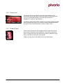
Installation Manual
BRP V810 RF-serial, year 2007-
Document number: Pivario_V1_004_EN_P1_20080217_Installation.doc
Foreword
Pivario V1 clutches can be mounted on a wide
range of snowmobiles. They broaden your
snowmobile’s range of use and the “freedom to
choose.”
Compliance with regulations and
standards
Guarantee
•
xxx
•
xxx
The guarantee is only valid if:
•
the equipment has been installed and
checked according to these instructions
•
the equipment has not been modified
without written approval from Pivario AB.
•
original spare are used for repairs
•
the equipment is used and maintained
according to the right user manual
The equipment is manufactured in compliance
with the following regulations and standards:
Information
These instructions apply to mechanical and
electrical installation and function testing of a
pivario V1 clutch. Configuration of the control
program and use and maintenance are
described in separate manuals.
IMPORTANT! Read the instructions carefully.
Incorrect use may result in personal injury or
damage to the equipment.
The pictures in these instructions are primarily
intended to show and clarify different parts of
the installation. Pictures may, in some cases,
show other snowmobile models similar than
those stated on the front of the installation
instructions.
Equipment and descriptions in these
instructions may be changed without prior
notice.
This publication contains information
protected by copyright law. No part of this
publication may be copied, reproduced, or
distributed in any form without the written
agreement of Pivario AB.
Copyright © Pivario AB, 2006
2
Pivario_V1_004_EN_P1_20080217_Installation.doc
1
Introduction..................................................................... 5
1.1
1.2
1.3
About this manual ................................................................................. 5
Technical description ............................................................................ 6
1.2.1
Clutch unit.............................................................................. 6
1.2.2
Control unit ............................................................................ 7
1.2.3
Control Panel......................................................................... 7
1.2.4
What is included? .................................................................. 8
ID Marking............................................................................................. 9
2
Safety............................................................................. 10
2.1
2.2
2.3
2.4
General information ............................................................................ 10
Warning symbols ................................................................................ 10
Safety instructions .............................................................................. 11
Safety features.................................................................................... 11
2.4.1
Belt guard ............................................................................ 11
3
Preparations.................................................................. 12
3.1
3.2
Disassembling the original clutch ....................................................... 12
Attaching the clutch to the chassis ..................................................... 12
4
Installation..................................................................... 13
4.1
4.2
Control Panel ...................................................................................... 13
Cables................................................................................................. 14
4.2.1
Cable for sensing “ignition on”............................................. 14
4.2.2
Cable for sensing “throttle position” (TPS) .......................... 15
4.2.3
Cables for voltage measurement ........................................ 17
Magnets on the secondary clutch ....................................................... 18
Clutch unit ........................................................................................... 19
4.4.1
Rear attachment for clutch .................................................. 20
4.4.2
Electrical connections.......................................................... 21
4.3
4.4
Pivario_V1_004_EN_P1_20080217_Installation.doc
5
Calibration and adaptation of the control program ... 22
5.1
5.2
5.3
Requirements...................................................................................... 22
Calibration........................................................................................... 22
5.2.1
Engagement calibration and function test ........................... 22
5.2.2
TPS calibration .................................................................... 22
Parameter settings.............................................................................. 22
5.3.1
Preparations ........................................................................ 22
5.3.2
Using the configuration unit................................................. 22
5.3.3
Checking the control program version ................................ 22
5.3.4
Entering parameter values .................................................. 22
6
Test driving ................................................................... 22
6.1
6.2
6.3
6.4
The first test drive ............................................................................... 22
Test the crawl function........................................................................ 22
Test the freeze function ...................................................................... 22
Troubleshooting .................................................................................. 22
3
4
Pivario_V1_004_EN_P1_20080217_Installation.doc
1
1.1
Introduction
About this manual
This manual describes the installation of the pivario V1 clutch on the
snowmobile model(s) indicated on the front of the manual. The
manual can also be used for other models of the same make,
provided that the chassis, engine type and electrical system do not
differ.
NOTE: The photo shows installation on a Lynx Adventure -2007.
IMPORTANT! The manual assumes that the person performing the
installation is knowledgeable about snowmobiles. Experience in
service and repair work on snowmobile clutches is recommended.
This manual is primarily intended for retailers who are also
responsible for installing the pivario V1 clutch.
Pivario_V1_004_EN_P1_20080217_Installation.doc
5
1.2
Technical description
The pivario V1 clutch replaces the primary clutch that was originally
mounted on the snowmobile. The clutch and its control equipment
have been developed and specially adapted to work alongside the
standard secondary clutch and drive belt.
1.2.1 Clutch unit
The clutch has no moving weight arms, and the gearing is instead
regulated by an electronic shift. The electronic shift affects a movable
arm, connected to the outer drive pulley. The principle is illustrated in
the following picture:
1
2
3
4
Component
1
Fixed drive pulley
2
Movable drive pulley
3
Control unit
4
Shift/Gear housing
5
Large bearing
6
Right arm
7
Small bearing
8
Central screw
9
Left arm
10
Rear attachment
5
6
6
7
8
9
10
Pivario_V1_004_EN_P1_20080217_Installation.doc
1.2.2 Control unit
The control unit is mounted on the clutch and contains all the
electronics and circuits used to store the clutch’s control programs.
The unit is embedded so that it can cope with variations in
temperature, moisture, and vibration.
On delivery from Pivario AB the control unit contains a basic program.
When installing the pivario V1 clutch the control parameters should
be optimized for the snowmobile on which it will be used.
1.2.3 Control Panel
Preset driving modes can be changed with the help of the control
panel which is placed on the handlebars. This makes it quick and
easy to change driving mode while driving. Some calibrations may
also be carried out using the control panel.
Please see the pivario User Manual for more information.
Pivario_V1_004_EN_P1_20080217_Installation.doc
7
1.2.4 What is included?
The clutch is delivered complete, including the control panel and
cables. Please check your delivery against the table/model below:
Component
Description
Primary clutch
Incl. control unit and
sensor
Central screw
Incl. 2 washers
Rear attachment
Incl. 1 attachment screw
and 2 washers
Magnets, 1 set
6 incl. attachment screws
for secondary clutch
Control Panel
Incl. mounted cable set
Cables
For voltage measurement,
incl. 20 A fuse
Cable accessories,
1 set
For connecting cables
from control panel
Article number
User manual
Sticker set
8
Pivario_V1_004_EN_P1_20080217_Installation.doc
1.3
ID Marking
Each clutch is marked with a unique serial number. The number is
engraved on the cover of the control unit.
Always state the serial number in correspondence with Pivario AB.
Pivario_V1_004_EN_P1_20080217_Installation.doc
9
2
2.1
Safety
General information
The pivario V1 clutch has been constructed and tested to fulfill current
safety requirements. Read the following safety instructions before
installation.
These instructions describe the safest and - in most cases - the most
practical installation procedure, but should never replace personal
responsibility or local safety regulations
Whenever performing installation- or any other type of work, always
pay proper attention to:
2.2
•
Your personal safety and that of others.
•
Product integrity, through correct installation according to these
instructions.
Warning symbols
The following warnings and important messages are used in these
instructions:
WARNING!
Warning (in bold text) with a warning symbol is used to highlight a risk
area that may result in personal injury.
IMPORTANT!
Important (in bold text) is used to show there is a risk of damage to
the equipment.
NOTE: (in bold) is used to highlight information that is important for
problem-free installation and use of the equipment.
10
Pivario_V1_004_EN_P1_20080217_Installation.doc
2.3
Safety instructions
The following safety instructions must always be adhered to (also pay
attention to other warnings that may be found in association with each
instruction):
WARNING!
Exercise caution if the engine/clutch must be test run without the belt
guard mounted. Avoid high revs and do not lean over the clutch.
WARNING!
Never stand in front of the snowmobile when the engine is started.
WARNING!
Never rev the engine if someone is standing in front of the
snowmobile.
WARNING!
The clutch’s shifting motor intermittently works with a great deal of
power. Never touch moving parts when the ignition is on or the
snowmobile’s engine is running.
2.4
Safety features
2.4.1 Belt guard
Unless otherwise stated, the snowmobile’s ordinary belt guard can be
used as protection from moving parts on the pivario V1 clutch. On the
RF chassie shall black cover been taken away or cuted so the Pivario
V1 vill fit.
If this is not effective for any reason, suitable protection must be
mounted. If necessary, contact Pivario AB.
Pivario_V1_004_EN_P1_20080217_Installation.doc
11
3
Preparations
Some disassembly and minor modifications to the snowmobile are
necessary before installation of the new clutch can begin. The
following section briefly describes all the necessary actions. For a
detailed disassembly description, also see the exploded views or the
snowmobile’s maintenance handbook (not included in the delivery
from Pivario AB).
3.1
Disassembling the original clutch
The original primary clutch should be disassembled from the engine’s
crankshaft journal.
IMPORTANT! Use an original puller that is adapted for disassembly
of the primary clutch. Use of other tools may damage both the clutch
and the crankshaft journal.
3.2
Attaching the clutch to the chassis
The pivario V1 clutch is primarily hung on the crankshaft journal, but
the rear end (shift housing) should also be anchored to the
snowmobile’s chassis via a flexible attachment. Prepare for the
attachment in the following way:
1. Open left side cover on the snowmobile.
2. Drill a hole (Ø 8.5) mm in the lower part of the side of the
cover. See the picture below.
55
50
12
Pivario_V1_004_EN_P1_20080217_Installation.doc
4
Installation
IMPORTANT! Disconnect the battery’s negative pole before
beginning installation. Connect it temporarily only in association with
necessary test measurements.
NOTE Installation is easiest if it is carried out in the order described.
I.e. finish the installation with mounting and connecting the actual
clutch unit.
4.1
Control Panel
The control panel should be placed on the left handlebar. The buttons
should be easily reached using the thumb, without needing to release
your hand from the handlebar.
Install the control panel in the following way:
1. Place the control panel on the handlebar. Screw it loosely
around the handlebar with the accompanying spring clamp.
IMPORTANT! Check that the handbrake handle can be used without
it colliding with the control panel.
2. Adjust the panel until it is in the right position. Make sure that
no cables are trapped. The cables should pass through the
opening in the spring clamp.
3. Tighten the screws alternately.
4. Remove the casing and padding around the handlebar.
Pivario_V1_004_EN_P1_20080217_Installation.doc
13
5. Lead the cables from the panel along the handlebar. Clip the
cables around the handlebar and the existing cabling.
6. Check that the cables can move freely for the full range of
handlebar movement.
4.2
Cables
IMPORTANT! Cable placement and connection has been thoroughly
tested by Pivario AB. For the guarantee to apply, the cables must be
installed and connected according to these instructions.
4.2.1 Cable for sensing “ignition on”
IMPORTANT! This stage requires that the snowmobile’s electrical
diagram is available. The cable colors shown on the pictures may
differ between different snowmobile models!
The red cable from the control panel should be connected to the
snowmobile’s electrical system to send the “ignition on” signal to the
clutch’s control unit. Use a test instrument to find the right cable.
IMPORTANT! The clutch’s control panel and control system should
only be live when the snowmobile’s ignition is on. If possible, any
current should stop as soon as the emergency stop is activated.
Connect the cable in the following way:
14
Pivario_V1_004_EN_P1_20080217_Installation.doc
1. Unscrew the plastic cover which houses the ignition key.
2. Locate the cable from the ignition and cut the cable casing
above the contact.
3. Locate the correct cable (in this case black/green) in the
cables above the contact and cut it off just above the contact.
IMPORTANT! Use proper cable clip pliers when mounting cable clips
and slicing sleeves. Use the accompanying splicing sleeves. These
contain melt adhesive and provide tension deloading after completed
assembly.
4. Splice the cable together again using the accompanying
splicing sleeve, along with the red cable from the control
panel.
5. Heat the splicing sleeve with a hot-air gun to protect the
branching. Clip the cable in the cable trunk.
4.2.2 Cable for sensing “throttle position” (TPS)
IMPORTANT! This stage requires that the snowmobile’s electrical
diagram is available. The cable colors shown on the pictures may
differ between different snowmobile models!
The black cable from the control panel should be connected to the
sensor on the snowmobile that registers the throttle’s position (current
throttle position). Use a test instrument to find the right cable.
Pivario_V1_004_EN_P1_20080217_Installation.doc
15
IMPORTANT! The cabling to the TPS sensor normally contains three
cables. The connection should be made to the cable in which voltage
varies when opening the throttle (normally 0 – 5 Volt).
Connect the cable in the following way:
1. Localize the cable and contact above the carburetors.
2. Localize the correct cable by turning on the ignition, opening
the throttle as wide as possible and measuring the voltage in
the TPS sensor’s cable connectors. The voltage should vary
on opening the throttle.
NOTE! In some cases the motor must also be started in order
for the TPS sensor to send a signal.
(In this case it is the white/red cable in the cabling above the
contact).
3. Cut off the cable right next to the contact.
IMPORTANT! Use proper cable clip pliers when mounting cable clips
and slicing sleeves. Use the accompanying splicing sleeves. These
contain melt adhesive and provide tension deloading after completed
assembly.
4. Splice the cable together again using the accompanying
splicing sleeve, along with the black cable from the control
panel.
5. Heat the splicing sleeve with a hot-air gun to protect the
branching. Clip the cable in the cable trunk.
16
Pivario_V1_004_EN_P1_20080217_Installation.doc
4.2.3 Cables for voltage measurement
Cables for voltage measurement should be connected from the clutch
unit to the battery’s positive and negative poles.
The cables, including the main fuse, are included in the delivery from
Pivario AB.
This is a suitable place for connecting the snowmobile’s jump start
cables, which run along the right side.
1. Remove the protective cover on the jump start cables and
screw on the cables.
IMPORTANT! Make sure that the cables do not come into contact
with hot surfaces or sharp edges.
2. Run the cables backwards and up under the plastic cover that
houses the ignition key. Clip on in suitable places using
bundling ties.
3. Make sure that the cable is placed and clipped on the left side
according to the picture below:
Pivario_V1_004_EN_P1_20080217_Installation.doc
17
4.3
Magnets on the secondary clutch
IMPORTANT! The magnets have a “north pole” and a “south pole.”
When mounting them they should face in alternate directions, so that
every other magnet has its “north pole” turned outwards.
The magnets must be mounted on the secondary clutch so that the
control unit is able to register the clutch’s rpm. Mount the magnets
with the accompanying screws in the clutch’s pre-threaded holes.
NOTE! The screws should be locked with screwlock, type “hard”
(Permabond 1046 green or similar).
18
Pivario_V1_004_EN_P1_20080217_Installation.doc
4.4
Clutch unit
The clutch unit is delivered complete from Pivario AB, so that
installation should be quick and easy.
Install the clutch unit in the following way:
1. Make sure the crankshaft journal is undamaged, clean and
dry.
2. Carefully push the clutch unit on the crankshaft journal.
3. Place the two washers on the central screw. Note that the
spring washer is to be closest to the head of the screw and
that the collar of the large washer is to be turned towards the
clutch.
IMPORTANT! Do not use the original central screw to mount the
pivario V1 clutch.
4. Mount the central screw. Hold central housing with the hook
wrench (there are predrilled holes in the housing; the hook
wrench is included in the workshop kit).
Pivario_V1_004_EN_P1_20080217_Installation.doc
19
5. Tighten using moments according to the snowmobile’s
maintenance handbook.
6. Rotate the clutch up and check the distance between the
sensor and the magnets on the secondary clutch. The
distance should be about 30 mm. Adjust the sensor’s position
if necessary.
4.4.1 Rear attachment for clutch
The rear attachment should be mounted on the bottom in balley in the
following manner:
20
Pivario_V1_004_EN_P1_20080217_Installation.doc
1. Place the washer with the larger hole on the screw.
2. Place the washer with the smaller hole on the inside of the
side cover and mount the screw from below.
3. Mount the attachment and tighten it by hand.
4. Rotate the clutch unit up to a horizontal position and
reassemble the snowmobile’s side cover.
5. Press the rear attachment onto the ball found on the rear end
of the shifting motor.
4.4.2 Electrical connections
1. Connect the black cable/contact from the control panel to the
control unit’s connector marked “Panel.”
2. Connect the red and black cables on the clutch unit to the
cabling from the battery (connector).
IMPORTANT! Make sure that no cables can come into contact with
the secondary clutch.
3. Clip the cables to the side cover.
Pivario_V1_004_EN_P1_20080217_Installation.doc
21
5
5.1
Calibration and adaptation of the control program
Requirements
On delivery from Pivario AB the clutch’s control unit normally contains
a basic program and a basic range of control parameters. When you
know the snowmobile (make and model) on which the clutch is to be
installed, certain control parameters should be adjusted. For this you
will need a configuration unit + cable. These are not part of the clutch
delivery from Pivario AB; they should be ordered separately:
Component
1
Configuration unit
5.2
Description
Article number
Incl. connection cable
Calibration
When the clutch has been completely installed you must carry out the
following calibrations before test driving the snowmobile. These can
be carried out without external equipment with the help of the control
panel on the handlebar.
NOTE: The LEDs on the control panel are never continuously lit,
instead they blink rapidly. This is absolutely normal and means that
they are easier to read in bright light.
H
M
L
In general, the buttons are used as follows when calibrating:
•
H+L are used to preselect the calibration mode.
•
H and L are used to choose the type of calibration, and to
increase/reduce the value or setting.
•
M is used to activate and confirm a calibration.
The relevant calibrations are described in detail below.
22
Pivario_V1_004_EN_P1_20080217_Installation.doc
NOTE: You can terminate a calibration procedure at any time by
turning off the ignition. No new settings will be saved and the clutch
will work as before.
5.2.1 Engagement calibration and function test
WARNING! The engagement calibration and function test must be
carried out before the snowmobile is started for the first time after the
clutch is installed.
WARNING! Do not start the motor. For safety reasons, this calibration
must be carried out with an immobile clutch.
The belt guard must be removed when calibration is carried out so
that the clutch’s movements can be observed.
The clutch’s engagement position is calibrated in the following
manner:
1. Check that the drive belt is load-free in the primary clutch, and
that the secondary clutch completely compressed.
2. Turn on the ignition.
3. Press and hold down both the H+L buttons until the M+L
LEDs blink (about 5 seconds).
4. Watch the clutch during this operation!
Press and hold down the M button. The drive pulley is now in
the initial position.
5. Watch the clutch during this operation!
Continue to hold down the M button. At the same time, press
the:
- H button to move the drive pulley towards the belt
- L button to move the drive pulley away from the belt.
6. Continue to hold down the M button and check that the drive
pulleys are precisely positioned against the belt. It should be
possible to move the belt, but it should not be loose between
the drive pulleys.
Make any necessary adjustments using the H and L buttons.
7. Release the M button. The new engagement position is now
saved, at the same time as the control program returns to the
driving mode.
Pivario_V1_004_EN_P1_20080217_Installation.doc
23
NOTE: If all three LEDs blink for a moment when the M button is
released, a fault has occurred during calibration. In this case the
calibration will not be saved.
5.2.2 TPS calibration
WARNING! The snowmobile is started during this calibration. Connect
an exhaust extractor or perform this calibration outdoors.
WARNING! Replace the belt guard before starting the motor.
WARNING! Make sure that no-one is standing in front of the
snowmobile before starting the engine.
The throttle’s position is calibrated using the control panel in the
following manner:
1. Start the snowmobile and let it run until it has warmed up and
is ready to use.
2. Release the accelerator entirely and let the snowmobile idle.
3. Press and hold down both the H+L buttons until the M+L
LEDs blink (about 5 seconds).
4. Press the H button to shift to TPS calibration. Now the M+H
LEDs should blink.
5. Hold the snowmobile’s brake in or put the parking brake on
during this operation!
Press and hold down the M button, and then completely open
the throttle for a moment. The release the throttle entirely.
6. Release the M button and allow the motor to return to idling
rpms.
The TPS calibration is complete when the diodes stop flashing (about
2 sec.). This calibration should normally only be carried out once, in
association with the first startup.
NOTE: If all three LEDs blink for a moment when the M button is
released, a fault has occurred during calibration. In this case the
calibration will not be saved.
24
Pivario_V1_004_EN_P1_20080217_Installation.doc
5.3
Parameter settings
Some control parameters should always be adjusted to suit the
snowmobile. Pivario AB continually tests pivario V1 on new models
and can help with the appropriate parameter values.
The descriptions below apply to basic adaptations that should
ALWAYS be done in order to get the right drive characteristics for
each snowmobile model.
It is possible to make further adjustments to obtain drive modes and
gear ratio characteristics that are personally adjusted or optimized for
special purposes. More information about this is available in a
separate Configuration Manual. Please contact Pivario AB for more
information.
5.3.1 Preparations
IMPORTANT! Make sure that the battery is fully charged and working
properly.
1. Remove the protective cover on the control unit’s screwed
connection marked “Data.”
2. Connect the configuration unit to the control unit’s connector
marked “Data.”
3. Turn the snowmobile’s ignition key to activate the clutch’s
control unit and the configuration unit.
Pivario_V1_004_EN_P1_20080217_Installation.doc
25
5.3.2 Using the configuration unit
A short description of how to use the configuration unit follows:
26
Button/Display
Field
1
“left”
Description
2
”right”
Select menu/ Navigate one row to the right
3
”up”
Navigate upwards between the rows
4
”down”
Navigate downwards between the rows
5
”enter”
Select and confirm parameter value
A
Parameter name
B
Parameter value
Select menu/ Navigate one row to the left
•
Choose menu (view) with the buttons 1 and 2:
- ”View 1” – Present values that change during driving
- ”View 2” – Log values for evaluation/troubleshooting
- ”View 3” – Parameter values independent of drive mode
- ”View 4” – Parameter values for each drive mode (L,M,H)
•
Navigate up/down in the parameter lists using buttons 3 and
4.
•
Select the marked value by quickly pressing button 5.
•
Move the marker right/left in the window with buttons 1 and 2.
•
Increase/reduce the marked value figure with buttons 3 and 4.
•
Press button 5 to transfer the adjusted parameter value to the
control unit (save).
•
Use the control panel on the handle bar to change between
parameter values for each driving mode in “View 4.”
Pivario_V1_004_EN_P1_20080217_Installation.doc
5.3.3 Checking the control program version
To make sure that the right parameters have been installed you must
first check which program version the control unit contains. This is
done using the configuration unit.
Shortly after the ignition is turned on, the control unit’s program
version is shown in the display window for 5-10 seconds, before
switching to “View 1.”
IMPORTANT! The updated control program may contain adjusted
parameter values. Always ensure the current parameter values are
used. Check the information about the program version and
publication date on the information sheet. If there are any
uncertainties, please contact Pivario AB.
5.3.4 Entering parameter values
The parameters that should be adjusted are described in a separate
information sheet for each make/model.
IMPORTANT! Only the parameter values stated on the information
sheet should be changed.
Follow the instructions in the section Using the configuration unit to
change and transfer adjusted values to the control unit. Note that a
value must be saved/transferred before the next value can be
changed.
Pivario_V1_004_EN_P1_20080217_Installation.doc
27
6
6.1
Test driving
The first test drive
After completed installation and calibration, the snowmobile should be
test driven with the new pivario V1 clutch. Test driving SHALL be
carried out before the snowmobile is transferred to the end customer.
NOTE: The pivario V1 clutch results in the snowmobile partly having
different drive characteristics. Engagement rpm, gear ratio
characteristics and disengagement rpm may differ from the same
snowmobile with a standard clutch.
For controlling and using the clutch’s control panel, see the User
Manual.
1. Start the snowmobile and warm up the engine according to
the snowmobile’s instructions.
2. Test drive the snowmobile with a light load. Start with drive
mode L and then change to M and H while driving.
The clutch should react immediately when the drive mode is
changed. Also check that the right LED on the control panel is
activated (blinking).
3. Release the gas and allow the snowmobile to “roll” on a hard
flat surface until it is standing still. Check that the snowmobile
is standing still and that the engine is running unstressed at
the normal idling rpm.
6.2
Test the crawl function
The crawl function works regardless of the current driving mode.
1. Dive the snowmobile at an even speed. Press and hold down
one of the buttons L, M or H.
2. Now check that after 1 second the clutch successively gears
down to the lowest gear ratio and locks itself there.
3. Release the accelerator. The clutch should now NOT
disengage; instead you should be able to crawl at the lowest
possible speed as far as the motor can take you.
28
Pivario_V1_004_EN_P1_20080217_Installation.doc
6.3
Test the freeze function
You can prevent the clutch engaging by using the freeze function.
Test this in the following way:
1. Start the engine and let it idle.
2. Press and hold down one of the buttons L, M or H.
3. Successively increase the motor’s rpm. The snowmobile
should remain still regardless of how far the throttle is opened.
6.4
Troubleshooting
If disturbances or abnormal functioning occurs during the test drive,
you should initially check the cabling for the clutch installation and
connections to the snowmobile’s electrical system.
Pivario_V1_004_EN_P1_20080217_Installation.doc
•
For faults and problems that can be due to hardware (clutch,
sensor and cabling), see the Troubleshooting section in the
User Manual.
•
If abnormal functioning remains after measures have been
taken according to the User Manual, it is probably connected
to the control program/parameter values:
- check that the parameter values for the right snowmobile
model are uploaded.
- Read the Configuration Manual for more information.
29
30
Pivario_V1_004_EN_P1_20080217_Installation.doc
Pivario_V1_004_EN_P1_20080217_Installation.doc
31
Pivario AB
Box 41, SE-835 21 Krokom, Sweden
Phone: +46 (0)640 171 70
Internet: www.pivario.com
Fax: +46 (0)640 616 26
32
Pivario_V1_004_EN_P1_20080217_Installation.doc