1
Instruction Manual
DIGITAL CONTROLLER
COMMUNICATION
FUNCTIONS (MODBUS)
TYPE: PXH
INP-TN514207b-E
Note: Windows® is the registered trade mark of Microsoft Corporation.
Note: Visual Basic® is the registered trade mark of Microsoft Corporation.
Note: MODBUS® is the registered trade mark of Gould Modicon.
Notice
z
Exemption items from responsibility
The contents of this document may be changed in the future without prior notice.
We paid the utmost care for the accuracy of the contents. However, we are not liable for direct
and indirect damages resulting from incorrect descriptions, omission of information, and use of
information in this document.
CONTENTS
CONTENTS....................................................................................................................... i
1.
COMMUNICATION FUNCTIONS ......................................................................................1
2.
1.1 Outline..........................................................................................................................1
SPECIFICATIONS.................................................................................................................2
3.
2.1 Communication Specifications ....................................................................................2
CONNECTION ......................................................................................................................3
4.
3.1 Communication Terminal Allocation ...........................................................................3
3.2 Wiring ..........................................................................................................................4
SETTING OF COMMUNICATION CONDITION...............................................................6
5.
4.1 Setting items.................................................................................................................6
4.2 Setting Operation Method ............................................................................................7
MODBUS COMMUNICATION PROTOCOL......................................................................8
6.
5.1 Outline..........................................................................................................................8
5.2 Composition of Message..............................................................................................9
5.3 Response of Slave Station ..........................................................................................11
5.4 Function Code ............................................................................................................12
5.5 Calculation of Error Check Code (CRC-16) ..............................................................13
5.6 Transmission Control Procedure................................................................................14
5.7 FIX Processing (Cautions in data write) ....................................................................16
DETAILS OF MESSAGE....................................................................................................17
7.
6.1 Read-out of Word Data [Function code: 03H]......................................................17
6.2 Read-out of Read-out Only Word Data [Function code: 04H]....................................19
6.3 Write-in of Word Data (1 word) [Function code: 06H]...............................................21
6.4 Write-in of Continuous Word Data [Function code: 10H] ..........................................22
ADDRESS MAP AND DATA FORMAT.............................................................................24
8.
7.1 Data Format................................................................................................................24
7.2 Communication Address Map....................................................................................29
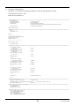
SAMPLE PROGRAM .........................................................................................................47
9.
TROUBLESHOOTING .......................................................................................................53
INP-TN514207a-E
i
1. COMMUNICATION FUNCTIONS
1.1 Outline
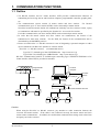
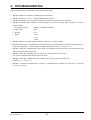
▪ Via RS-485 interface and PC loader interface, PXH provides communication functions of
transmitting and receiving data to and from host computer, programmable controller, graphic panel,
etc.
▪ The communication system consists of master station and slave stations.
For RS-485
communication, up to 31 slave stations (PXHs) can be connected per master station.
Note that, because the master station can communicate with only one slave station at a time, a party
to communicate with must be specified by the "Station No." set at each slave station.
For loader communication, one slave station (PXH) can be connected per master station.
▪ In order that the master station and slave station can communicate, the format of the
transmit/receive data must coincide. For the PXH, the format of the communication data is
determined by the MODBUS protocol.
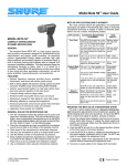
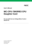
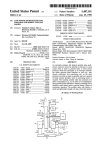
▪ Please use an RS-232C ⇔ RS-485 converter in case of designating a personal computer or other
devices which have an RS-232C interface as a master station.
[RS-232C ⇔ RS-485 converter] (recommended article)
Type: RC-77 (isolated type)/ RA SYSTEMS make http://www.ras.co.jp
Type: K3SC-10 (isolated type)/ OMRON make http://www.omron.co.jp
RS-232C communication with PC is available upon connecting Type: ZZPPXH1*TK4H4563 to PC
loader interface where PXH is provided in standard.
Personal
computer
Programmable
controller
RS-232C
D-sub9 pin
PC loader
interface
RS-485
RS-232C
RS-232C
RS-485
RS-485 communication converter
Caution:
When using the RS-232C ⇔ RS-485 converter, pay attention to cable connection between the
converter and master station. If the cable is not connected correctly, the master station and slave
station cannot communicate. In addition, be careful about communication settings such as baud rate
and parity set for the converter.
INP-TN514207a-E
1
2. SPECIFICATIONS
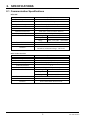
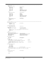
2.1 Communication Specifications
■ RS-485
Item
Specification
Electrical specification
Transmission method
Synchronous system
Connection format
Number connectable units
Transmission distance
Transmission speed
Data format
Based on EIA RS-485
2-wire, half duplex
Start-stop synchronous system
1:N
Up to 31 units
500m max. (total extension distance)
9600bps, 19200bps, 38400bps
Data length
8 bits
Stop bit
1 bit
Parity
none, even, odd (selectable)
HEX value (MODBUS RTU mode)
CRC-16
Functional isolation between transmission circuit
and others (withstand voltage : 500V AC)
Transmission code
Error detection
Isolation
■ PC loader interface
Item
Electrical specification
Transmission method
Synchronous system
Connection format
Transmission speed
Data format
Transmission code
Error detection
Isolation
Specification
EIA RS232C
3-wire, half duplex, bit-sereal
Start-stop synchronous system
1:1
9600bps, 19200bps, 38400bps
Data length
8 bits
Stop bit
1 bit
Parity
none, even, odd (selectable)
HEX value (MODBUS RTU mode)
CRC-16
Non-isolated from internal circuit
2
INP-TN514207a-E
3. CONNECTION
WARNING
For avoiding electric shock and malfunctions, do not turn on the power supply until all wiring is
completed.
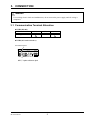
3.1 Communication Terminal Allocation
■ PXH9 (RS-485)
Terminal number
Signal name
(14)
RS485
+
(15)
SG
■ PXH9 (PC loader interface)
PC loader interface
Φ2.5, 3-pole miniature jack
INP-TN514207a-E
3
(16)
RS485
–
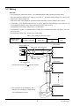
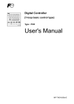
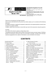
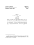
3.2 Wiring
■ RS-485
▪ Use twisted pair cables with shield.
Recommended: KPEV-SB (Furukawa Electric make)
▪ The total extension length of the cable is up to 500 m.
PXH can be connected per line.
A master station and up to 31 units of the
▪ Both ends of the cable should be terminated with terminating resistors 100Ω (1/2W or more).
▪ If the PXH is to be installed where the level of noise applied to the PXH may exceed 1000 V, it is
recommended to install a noise filter in the master station side as below.
Recommended noise filter: ZRAC2203-11 (TDK make)
▪ If problematic in EMC at communication, loading the communication cable with ferrite can lower
the noise level.
Recommended ferrite core: ZCAT series (TDK make)
MSFC series (Morimiya Electric make)
Master station
(PC, etc.)
RS-232C⇔RS-485
Noise filter
Transmission
cable
PXH
Slave (PXH)
Master station side
Twisted pair cable with shield
+
+
SG
SG
Terminating resistor
100Ω (1/2W)
Slave (PXH)
RS-485 interface
or
RS-485 side of the RS-232C
RS-485 converter
+
SG
Slave (PXH)
+
▪ SG connection is not mandatory, but is
effective for remedying communication
errors attributable to noises.
Terminating
resistor
100Ω (1/2W)
4
SG
INP-TN514207a-E
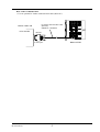
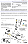
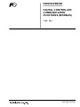
■ PC loader communication
▪ Use an optional PC loader communication cable (RS-232C).
PC loader communication cable
(RS232C)
ZZPPXH1 * TK4H4563
Master station side
PC or the like
RS232C
D-Sub 9 pins
INP-TN514207a-E
Bottom of PXH
5
4. SETTING OF COMMUNICATION CONDITION
In order that the master station and instrument (PXH) can correctly communicate, following settings are
required.
▪ All communication condition settings of the master station and those of instruments (PXH) are indentical.
▪ For RS-485 communication, different "station numbers (STN4)" are assigned to all PXHs which are
connected to a common line. (Any "Station No." is not shared by more than one instrument.)
▪ For PC loader communication, the station No. is fixed at "1".
Both for PC loader communication and RS-485 communication, same station No. "1" may be assigned.
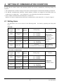
4.1 Setting items
The parameters to be set are shown in the following table.
keys.
Set them by operating the front panel
■ RS-485
CH B COM
Parameter
symbol
Item
SPD4
Transmission
speed
38400bps
―――
―――
Data length
Stop bit
8 bits
1 bit
BIT4
Parity setting
odd
STN4
Station No.
Value at
delivery
Setting range
96 : 9600bps
192 : 19200bps
384 : 38400bps
Fixed (can not be changed)
Fixed (can not be changed)
8n : none parity
8o : odd parity
8E : even parity
1
0 to 255
(0: communication function stop)
Setting range
Remarks
Set the same
communication
condition to
the master station
and all slave
stations.
Set a different
number to each
station.
■ PC loader communication
CH B COM
Parameter
symbol
Item
Value at
delivery
SPD2
Transmission
speed
38400bps
―――
―――
Data length
Stop bit
8 bits
1 bit
BIT2
Parity setting
odd
―――
Station No.
1
96 : 9600bps
192 : 19200bps
384 : 38400bps
Fixed (can not be changed)
Fixed (can not be changed)
8n : none parity
8o : odd parity
8E : even parity
Fixed (can not be changed)
6
Remarks
Set the same
conditions as
the master station.
INP-TN514207a-E
4.2 Setting Operation Method
The following example shows how to set the communication conditions.
Example: For RS-485, set BIT4 parity at even and STN4 at 18.
Key
operation
Indication
01SV
LP
200
200
Description
Operation status (PV/SV indication) or (PV/MV indication)
PS1
0000
Press the SEL key to display PS1.
b
COM
Ch
Press the ∨ key repeatedly until b.COM channel appears. (If
past over, press the ∧ key to return.)
SEL
b.
02
STN4
1
Press the SEL key to display STN4 parameter.
SEL
b.
02
STN4
00001
Press the SEL key. The numeric value on the lower
indicator blinks and the setting mode is selected.
>∧∨
b.
02
STN4
00018
Press the >, ∧, or ∨ key to change the numeric value to 18.
SEL
b.
02
STN4
18
Press the SEL key again. The numeric value stops blinking
and the setting is registered.
∨
b.
04
BIT4
8o
Press the ∨ key to display the BIT4 parameter.
SEL
b.
04
BIT4
8o
Press the SEL key. The numeric value on the lower
indicator blinks and the setting mode is selected.
∧∨
b.
04
BIT4
8E
Press the ∧ or ∨ key until the numeric value changes to 8E
(even parity).
SEL
b.
04
BIT4
8E
Press the SEL key again. The numeric value stops blinking
and the setting is registered.
b
COM
Ch
Press the DISP key to resume b.COM channel indication.
SEL
∨
DISP
DISP
01SV
LP
200
200
Press the DISP key to resume the operation status (PV/SV
indication).
* Be sure to turn off and on power so that the communication condition settings will affect the control.
INP-TN514207a-E
7
5. MODBUS COMMUNICATION PROTOCOL
5.1 Outline
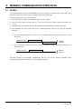
The communication system by the MODBUS protocol is that the communication always starts from
the master station and a slave station responds to the received message.
Transmission procedures is as shown below.
1) The master station sends a command message to a slave station.
2) The slave station checks that the station No. in the received message matches with the own station No.
or not.
3) If matched, the slave station executes the command and sends back the response message.
4) If mismatched, the slave station leaves the command message and wait for the next command
message.
a) In case when the station No. in the received command message matches with the own slave
station No.
Master to slave
Command message
Slave to master
Response message
Data on
the line
b) In case when the station No. in the received command message mismatches with the own
slave station No.
Master to slave
Command message
(Not respond)
Slave to master
Data on
the line
The master station can individually communicate with any one of slave stations connected on the
same line upon setting the station No. in the command message.
8
INP-TN514207a-E
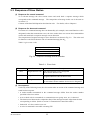
5.2 Composition of Message
Command message and response message consist of 4 fields; Station No., Function code, Data and
Error check code. And these are sent in the following order.
Station No. (1 byte)
Function code (1 byte)
Data (2 to 69 bytes)
Error check code (CRC-16) (2 bytes)
Fig. 5-1
Composition of message
In the following, each field is explained.
(1) Station No
Station No. is the number specifying a slave station. For RS-485 communication, the command
is processed only by the slave station whose station No. matches with the No. set in the
parameter "STN4".
For details of setting the parameter "STN4", refer to chapter 4.
For PC loader communication, the station No. is fixed at "1".
(2) Function code
This is a code to designate the function executed at a slave station.
For details, refer to section 5.4.
(3) Data
Data are the data required for executing function codes.
function codes. For details, refer to chapter 6.
The composition of data varies with
A register number is assigned to each data in the indicating controller.
communication, designate the register number.
For using the data by
Note that the register number transmitted on message is expressed as its relative address.
The relative address is calculated by the following expression.
Relateve address = The lower 4 digits of the Register number – 1
For example, when the resister number designated by a function code is 40003,
Relative address = (lower 4 digits of 40003) – 1
= 0002
is used on the message.
INP-TN514207a-E
9
(4) Error check code
This is the code to detect message errors (change in bit) in the signal transmission.
On the MODBUS protocol (RTU mode), CRC-16 (Cycric Redundancy Check) is applied.
For CRC calculation method, refer to section 5.5.
10
INP-TN514207a-E
5.3 Response of Slave Station
(1) Response for normal command
To a relevant message, the slave station creates and sends back a response message which
corresponds to the command message. The composition of message in this case is the same as
in section 5.2.
Contents of the data field depend on the function code.
For details, refer to Chapter 6.
(2) Response for abnormal command
If contents of a command message have an abnormality (for example, non-actual function code is
designated) other than transmission error, the slave station does not execute that command but
creates and sends back a response message at error detection.
The composition of response message at error detection is as shown in Fig. 5-2.
for function code field is function code of command message plus 80H.
The value used
Table 5-1 gives error codes.
Station No.
Function code + 80H
Error code
Error check(CRC-16)
Fig. 5-2
Response message at error detection
Table 5-1
Error code
01H
Contents
Illegal function code
02H
Illegal data address
03H
Illegal data value
Error Code
Description
Non-actual function code is designated.
Check for the function code.
A relative address of resister number to which the
designated function code can not be used.
Because the designation of number is too much,
the area where resister numbers do not exist is designated.
(3) No response
Under any of the following items, the slave station takes no action of the command message and
sends back no response.
▪ A station number transmitted in the command message differs from the station number
specified to the slave station.
▪ A error check code is not matched, or a transmission error (parity error, etc.) is detected.
▪ The time interval between the composition data of the message becomes longer than the time
corresponding to 24 bits. (Refer to section 5.6 Transmission Control Procedure.)
▪ Station No. of a slave station is set as 0.
▪ A write-in command is sent while executing FIX.
INP-TN514207a-E
11
5.4 Function Code
According to MODBUS protocol, register numbers are assigned by function codes.
Each function code acts on specific register number.
This correspondence is shown in Table 5-2, and the message length by function is shown in Table 5-3.
Table 5-2
No.
03H
04H
06H
10H
Correspondence between function codes and objective address
Function code
Function
Object
Read-out
Holding register
(continuously)
Read-out
Input register
(continuously)
Write-in
Holding register
Write-in
Holding register
(continuously)
Table 5-3
Resister No.
Contents
No.
4xxxx
Read-out/write-in word data
3xxxx
Read-out
4xxxx
Read-out/write-in word data
4xxxx
Read-out/write-in word data
word data
Function code and message length
[Unit:byte]
Function
code
03H
04H
*1
06H
10H
Contents
Read-out of word data
Read-out of word data
(read-out only)
Write-in of word data
Write-in of continuous
word data
Number of
designatable
data
32 words
Command message
Response message
Minimum Maximum Minimum Maximum
8
8
7
69
15 words
8
8
7
35
1 word
8
8
8
8
32 words
11
73
8
8
*1) For PXH, all data is designated by 2 words.
If 06H (write-in of word data) is used, only 1 lower word can be written in, and only 1 upper word
cannot.
12
INP-TN514207a-E
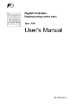
5.5 Calculation of Error Check Code (CRC-16)
CRC-16 is the 2-byte (16-bits) error check code.
end of the data field are calculated.
From the top of the message (station No.) to the
The slave station calculates the CRC of the received message, and does not respond if the calculated
CRC is different from the contents of the received CRC code.
Fig. 5-3 shows the flow of the CRC-16 calculation system.
Start
Set FFFFH (hexadecimal number) in CR.
Explanation of variables
CR : CRC error check data (2 bytes)
I : Digits of calculation characters
in command message
J : Check on the number of times
of CR calculation
Set 1 in I.
Exclusive logical sum (XOR) is executed
with CR and one character (1 byte) of the I
characters, and its results is set in CR.
Set 1 in J.
Bit at right end
of CR is 1?
NO
YES
Shift CR to right by 1 bit, and A001H and
exclusive logical sum (XOR) are executed
and its result is set in CR.
Shift CR to right by 1 bit.
Add 1 to J.
NO
Calculation (8 times)
is finished?
J>8
YES
Add 1 to I.
NO
Calculation of all characters is
completed?
I>All characters
YES
End
Fig. 5-3
INP-TN514207a-E
(Calculation is executed in the order
of command message station No.,
function code and data.)
CR calculation result shall be added
to the last command message in the
order of LOW byte and HIGH byte.
Flow of CRC-16 calculation
13
5.6 Transmission Control Procedure
(1) Transmission procedure of master station
The master station must proceed to a communication upon conforming to the following items.
(1-1)
Before sending a command message, provide 48 bits time or more vacant status.
(1-2)
For 1 command message, each field part should be sent below 24 bits time interval.
(1-3)
Within 24 bits time after sending a command message, receiving stand-by status
starts.
(1-4)
Provide 48 bits time or more vacant status between the end of response message
reception and beginning of next command message sending [same as in (1-1)].
(1-5)
For ensuring the safety, make a confirmation of the response message and make an
arrangement so as to provide 3 or more retries in case of no response, error
occurrence, etc.
Note) The above definition is minimum requirement. For ensuring the safety, it’s
recommended the program for the master should be developed with 2 to 3 times
margins. Concretely, it is advised to arrange the program for 9600 bps with 10 ms
or more for vacant status (1-1), and within 1 ms for byte interval (1-2) and
changeover from sending to receiving (1-3).
(2) Description
1) Detection of the message frame
Since the communication system uses the 2-wire RS-485 interface, there may be 2 statuses
on a line below. (The same goes with PC loader communication.)
(a) Vacant status (no data on line)
(b) Communication status (data is existing)
Instruments connected on the line are initially at a receiving status and monitoring the line.
When 24 bits time or more vacant status has appeared on the line, the end of preceding frame
is assumed and, within following 24 bits time, a stand-by status is posted. When data
appears on the line, the instruments enter on receiving, and when 24 bits time or more vacant
status is detected again, and the end of that frame is assumed. I.e., data which appeared on
the line from the first 24 bits time or more vacant status to the next 24 bits time or more
vacant status is fetched as one frame.
Therefore, one frame (command message) must be sent upon confirming the following.
(1-1)
48 bits time or more vacant status precedes the command message sending.
(1-2)
For 1 command message, each byte should be sent below 24 bits time interval.
2) Response of this instrument (PXH)
After a frame detection (24 bits time or more vacant status is detected), this instrument
carries out processing with that frame as a command message. If the command message is
addressed to the own station, a response message is returned. Its processing time is about
10 ms (depends on contents of command message).
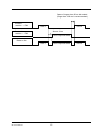
After sending a command message, therefore, the master station must observe the following
(1-3)
Stand-by status is posted within 24 bits time after sending a command message.
14
INP-TN514207a-E
Space of longer than 50 ms is needed.
(longer than 100 ms is recommended.)
Control
station → PXH
POL1
POL2
About 10 ms
Control
station ← PXH
POL1 response data
Data on line
POL1
INP-TN514207a-E
POL1 response data
15
POL2
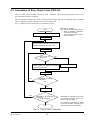
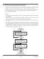
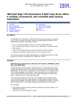
5.7 FIX Processing (Cautions in data write)
The instrument is provided inside with a non-volatile memory (EEPROM) for holding the setting
parameters. Data written in the non-volatile memory is not lost even if turning off the power.
To hold parameters that were written in the internal memory via communication after turning off the
power, the FIX process is effective. It allows parameters to be written in nonvolatile memory.
Fig. 5-4 shows the FIX procedure.
Cautions:
▪ FIX processing takes approximately 5 seconds to 3 minutes (depending on how many parameters
were changed).
▪ While writing, do not turn off the power of the PXH. Otherwise, the data in the non-volatile
memory will be destroyed, whereby the PXH could not be used any longer.
▪ Don’t change parameters on the front panel when performing the FIX procedure, or memory error
may result.
▪ The non-volatile memory (EEPROM) is a device where the number of write-in times is limited.
The guaranteed number of write-in times of the non-volatile memory used on the instrument is
100,000 minimum. Therefore, limit the times of FIX processing to bare minimum, like when
setting parameters are changed. Refrain from carrying out the FIX processing periodically for
example or while such is not absolutely required.
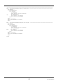
Start FIX
Read the FIX address
with function code : 03H
relative address : 0C50H
No
FIX=0?
Yes
Write ‘1’ into FIX address
with function code : 06H
relative address : 0C50H
Read the FIX address
with function code : 03H
relative address : 0C50H
No
FIX=0?
Yes
End FIX
Fig. 5-4
FIX procedure
16
INP-TN514207a-E
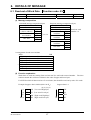
6. DETAILS OF MESSAGE
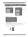
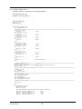
6.1 Read-out of Word Data [Function code: 03H]
Function code Max. word number read-out in one message Relative data address
03H
32 words
0000H – 01388H
Register No.
40001-45001
(1) Message composition
Command message composition (byte)
Response message composition (byte)
Station No.
Station No.
Function code
Function code
Read-out word
Upper
Read-out byte number
Read-out start No.
(relative address)
Lower
Upper number × 2
State of the first
word data
Upper
Lower
Read-out
1 to 32
word number
Lower
Upper
State of the next
word data
Upper
Lower
CRC data
Lower
∼
∼
Upper
State of the last
word data
Lower
Upper
CRC data
Lower
* Arrangement of read-out word data
MSB
LSB
Upper byte of contents of the first word data
Lower byte of contents of the first word data
Upper byte of contents of the next word data
Lower byte of contents of the next word data
∼
∼
Upper byte of contents of the last word data
Lower byte of contents of the last word data
(2) Function explanation
Words data are read-out, starting from read-out start No. until read-out word number.
station transmits the read-out word data in the order of upper and lower bytes.
The slave
For PXH for which all data consists of 2 word units, data should be read out by units of 2 words.
Example: Suppose data is 99999 (00 01 86 9FH)
Suppose data is 1
(1) (2) (3) (4)
INP-TN514207a-E
(3)
86
LH(Low word High byte)
00
LH
(4)
9F
LL(Low word Low byte)
01
LL
(1)
00
HH(High word High byte)
00
HH
(2)
01
HL(High word Low byte)
00
HL
17
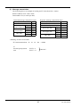
(3) Message transmission
The following shows an example of reading out PV1F (PV1 full scale) from No. 1 station.
Relative address of PV1F (PV1 full scale): 0830H
Number of data words: 02H (2 words per data)
Command message composition (byte)
Station No.
01H
Function code
03H
08H
Read-out start No. Upper
(relative address) Lower
30H
Upper
00
Read-out
H
word number
Lower
02H
Upper C6H
CRC data
Lower
64H
Response message composition (byte)
Station No.
01H
Function code
03H
Read-out byte number
04H
Upper
0FH
PV1F lower data
Lower
A0H
Upper
00H
PV1F upper data
Lower
00H
Upper
F9H
CRC data
Lower
05H
* Meaning of read-out word data
Upper data
PV1F (PV1 full scale)
00 00
18
Lower data
0F
A0H = 4000
INP-TN514207a-E
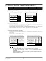
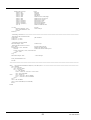
6.2 Read-out of Read-out Only Word Data [Function code: 04H]
Function code Max. word number read-out in one message Relative data address
04H
15 words
0000H – 057E H
Register No.
30001-31407
(1) Message composition
Command message composition (byte)
Response message composition (byte)
Station No.
Station No.
Function code
Function code
Upper
Read-out byte number
Read-out start No.
Read-out word
(relative address)
Lower
Upper number × 2
State of the first
word data
Upper
Lower
Read-out
1 to 15
word number
Lower
Upper
State of the next
word data
Upper
Lower
CRC data
Lower
∼
∼
Upper
State of the last
word data
Lower
Upper
CRC data
Lower
* Arrangement of read-out word data
MSB
LSB
Upper byte of contents of the first word data
Lower byte of contents of the first word data
Upper byte of contents of the next word data
Lower byte of contents of the next word data
∼
∼
Upper byte of contents of the last word data
Lower byte of contents of the last word data
(2) Function explanation
Words data are read-out, starting from read-out start No. until read-out word number.
station transmits the read-out word data in the order of upper and lower bytes.
The slave
For PXH for which all data consists of 2 word units, data is read out by units of 2 words.
(1) (2) (3) (4)
Example: Suppose data is –2 (FF FF FF FEH)
INP-TN514207a-E
(3)
FF
LH
(4)
FE
LL
(1)
FF
HH
(2)
FF
HL
19
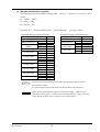
(3) Message transmission
The following shows an example of reading out PV value from No. 1 station.
Relative address of PV value: 0102H
Data number: 02H (2 words per data)
Command message composition (byte)
Station No.
01H
Function code
04H
01H
Read-out start No. Upper
(relative address) Lower
02H
Upper
00
Read-out
H
word number
Lower
02H
Upper D1H
CRC data
Lower F7H
Response message composition (byte)
Station No.
01H
Function code
04H
Read-out byte number
04H
Upper
38H
PV1 lower data
Lower
80H
Upper
00H
PV1 upper data
Lower
01H
Upper
36H
CRC data
Lower
CCH
* Meaning of read-out word data
PV1 measurement data 00
If
decimal point position
unit
01
38
80H = 80000
PV1D = 2
PV1U = °C
800.00°C
20
INP-TN514207a-E
6.3 Write-in of Word Data (1 word) [Function code: 06H]
Function code Max. word number write-in in one message
06H
1 word
Relative data address Register No.
40001−45001
0000H−01388H
(1) Message composition
Command message composition (byte)
Station No.
Function code
Response message composition (byte)
Station No.
Function code
Write-in designate No. Upper
(relative address)
Lower
Upper
Write-in word
data
Lower
Upper
CRC data
Lower
Write-in designate No. Upper
(relative address)
Lower
Upper
Write-in word
data
Lower
Upper
CRC data
Lower
(2) Function explanation
Designated data is written in word data of write-in designate No.
from master station in the order of upper and lower bytes.
Write-in data are transmitted
For PXH, all data consist of 2 word units. If 06H (write-in of word data) is used, only 1 lower
word of 2 word data can be written in, and only 1 upper word of 2 word data cannot.
(3) Message transmission (example)
The following shows an example of setting 100.0 (1000D=03E8H) to the parameter "P1" of No.1
slave station.
Parameter "P1"
Relative address: 0282H
Command message composition (byte)
Station No.
01H
Function code
06H
Response message composition (byte)
Station No.
01H
Function code
06H
Write-in designate No. Upper
(relative address)
Lower
State of write-in
Upper
designation
Lower
Upper
CRC data
Lower
Write-in designate No.
(relative address)
Note
INP-TN514207a-E
02 H
82H
03H
E8H
28H
E4H
State of write-in
designation
CRC data
Upper
02H
Lower
Upper
Lower
Upper
Lower
82H
03H
E8H
28H
E4H
When setting is being locked, response is returned normally, but the command is not
executed. Make sure that setting is not locked to send the write-in command.
The setting lock parameter can be written in even if communication setting is
invalidated.
If the write-in command message is sent to any slave station during the FIX process,
response is not returned from it.
21
6.4 Write-in of Continuous Word Data [Function code: 10H]
Function code
10H
Max. word number write-in in one message
32 words
Relative data address Register No.
40001−45001
0000H−01388H
(1) Message composition
Command message composition (byte)
Station No.
Function code
Write-in start No. Upper
(relative address) Lower
Upper
Write-in word
1 to 32
number
Lower
Write-in word
Write-in byte number
number × 2
Upper
First write-in
word data
Lower
Upper
Next write-in
word data
Lower
∼
∼
Upper
Last write-in
word data
Lower
Upper
CRC data
Lower
Response message composition (byte)
Station No.
Function code
Upper
Write-in start No.
(relative address)
Lower
Upper
Write-in word
number
Lower
Upper
CRC data
Lower
* Arrangement of write-in word data
MSB
LSB
Upper byte of contents of the first word data
Lower byte of contents of the first word data
Upper byte of contents of the next word data
Lower byte of contents of the next word data
∼
∼
Upper byte of contents of the last word data
Lower byte of contents of the last word data
(2) Function explanation
Words data are written in, starting from write-in start No. until write-in word number.
word data are transmitted from master station in the order of upper and lower bytes.
Write-in
For PXH for which all data consists of 2 word units, write in data by units of 2 words in the order
illustrated below.
Lower word, upper byte (LH)
Lower word, lower byte (LL)
Upper word, upper byte (HH)
Upper word, lower byte (HL)
22
INP-TN514207a-E
(3) Message transmission (example)
The following shows an example of writing-in P1 = 100.0, I1 = 10, and D1 = 5.0 to No. 1 slave
station.
P1 = 03E8H (= 1000D)
I1 = 0064H (= 100D)
D1 = 0032H (= 50D)
Parameter "P1"
Relative address:0282H
Command message composition (byte)
Station No.
01H
Function code
10H
Upper
02H
Write-in start No.
Lower
82H
Write-in word
Upper
00H
number
Lower
06H
Write-in byte number
0CH
Upper
03H
P1 lower data
Lower
E8H
Upper
00H
P1 upper data
Lower
00H
Upper
00H
I1 lower data
Lower
64H
Upper
00H
I1 upper data
Lower
00H
Upper
00H
D1 lower data
Lower
32H
Upper
00H
D1 upper data
Lower
00H
Upper
B6H
CRC data
Lower
D8H
Point
Caution
INP-TN514207a-E
Data number:06H
(2 words per data)
Response message composition (byte)
Station No.
01H
Function code
10H
Upper
02H
Write-in start No.
Lower
82H
Write-in
Upper
00H
word number
Lower
06H
Upper
E1H
CRC data
Lower
9BH
Since the transmission data can not include a decimal point, data of 100.0 is
transmitted as "1000".
For transmission format of each data, refer to the address map (Chapter 7).
When setting is being locked, response is returned normally. However, the
command is not executed. If the write-in command message is sent to any slave
station during the FIX process, response is not returned from it.
23
7. ADDRESS MAP AND DATA FORMAT
7.1 Data Format
7.1.1 Transmission data format
The MODBUS protocol used in this instrument (PXH) is RTU (Remote Terminal Unit) mode.
Transmitted data is "numeric value" and not "ASCII code".
7.1.2 Engineering unit
This instrument can handle set value data or other data which are affected by input range as follows.
Engineering unit: Subjected to scaling to match the actual value according to input range
[Example] The value of "PV = 150" (input range: 0º to 400ºC)
Engineering unit
Register No.
0102
Data (HEX)
00000096H
→
Data (decimal)
150
● How to change the input range setting via communication
The input range setting is for full scale, base scale and decimal point position setting.
In order that the change of input range setting will affect the control, power must be turned off and
on, or the reset command must be executed.
Changing the decimal point position automatically changes the full scale and base scale settings.
Example: Changing the input range from 0 to 400, to 0.0 to 400.0
(1) PV1D = 0 → 1 (automatically changes as PV1F = 400 → 400.0, PV1B = 0 → 0.0)
↓
(2) FIX command (see 5.7)
↓
(3) Power OFF-ON or execute reset command (write 1 at relative address 0060H)
● Input range dependent data (see communication address map)
Input range dependent data must be reset after turning off and on power or after transmitting a reset
command subsequent to a change of input range.
(1) Input range setting change
↓
(2) FIX command (see 5.7)
↓
(3) Power off and on or execute reset (write 1 at relative address 0060H)
↓
(4) Reset all data depending upon by input range
24
INP-TN514207a-E
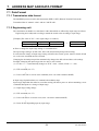
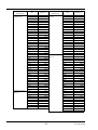
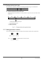
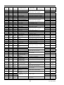
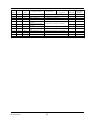
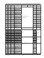
7.1.3 Handling of decimal point
No decimal point is added to transmission data.
For data given in the following table, carry out an alignment of decimal point.
should be removed in transmission, and should be added in receiving data.)
(Decimal point
Word data [read-out/write-in]
Digits below
decimal point
Designate by UCD1
if TPLT = 10, 11,
30, 31, 50, 51
(0 to 3)
Designate by PV1D
if TPLT = 13, 14,
33, 34, 53, 54
(0 to 3)
INP-TN514207a-E
Kind
Register No.
AL1
40257
A1-L
40257
A1-H
AL2
A2-L
A2-H
AL3
A3-L
A3-H
AL4
A4-L
A4-H
AL5
A5-L
A5-H
AL6
A6-L
A6-H
AL7
A7-L
A7-H
AL8
A8-L
A8-H
1HYS
2HYS
40259
40273
40273
40275
40289
40289
40291
40305
40305
40307
40321
40321
40323
40337
40337
40339
40353
40353
40355
40369
40369
40371
40265
40281
3HYS
4HYS
5HYS
6HYS
7HYS
8HYS
SV_L1
ARH1
ARL1
SH1
SL1
HS1
SV1
ARH1
ARL1
HYS1
REF1
SV2
ARH2
ARL2
HYS2
REF2
SV3
ARH3
ARL3
40297
40313
40329
40345
40361
40377
40641
40651
40653
40655
40657
40671
41025
41035
41037
41039
41047
41057
41067
41069
41071
41079
41089
41099
41101
25
Digits below
decimal point
Designate by UCD1
if TPLT = 10, 11,
30, 31, 50, 51
(0 to 3)
Designate by PV1D
if TPLT = 13, 14,
33, 34, 53, 54
(0 to 3)
Designate by PV1D
(0 to 3)
Designate by PV2D
(0 to 3)
Designate by AI1D
(0 to 3)
Designate by UCD1
(0 to 3)
1 digit below
decimal point
Kind
HYS3
Register No.
41103
REF3
41111
SV4
ARH4
ARL4
HYS4
REF4
SV5
ARH5
ARL5
HYS5
REF5
SV6
ARH6
ARL6
HYS6
REF6
SV7
ARH7
ARL7
HYS7
REF7
PV1F
PV1B
PV1Z
PV1S
41121
41131
41133
41135
41143
41153
41163
41165
41167
41175
41185
41195
41197
41199
41207
41217
41227
41229
41231
41239
42097
42099
42107
42109
PV2F
PV2B
PV2Z
PV2S
AI1F
AI1B
AI1Z
AI1S
UCF1
UCB1
P1
I1
D1
MVH1
MVL1
DMV1
BAL1
PMV1
ALP1
BET1
P-1
I-1
D-1
BL-1
P-2
42129
42131
42139
42141
42193
42195
42203
42205
42081
42083
40643
40645
40647
40659
40661
40667
40677
40685
40833
40841
41027
41029
41031
41045
41059
Digits below
decimal point
1 digit below
decimal point
Designate by PV1D
(0 to 3)
Kind
Register No.
I-2
D-2
BL-2
P-3
I-3
D-3
BL-3
P-4
I-4
D-4
BL-4
P-5
I-5
D-5
BL-5
P-6
I-6
D-6
BL-6
P-7
I-7
D-7
BL-7
P1CU
P1TF
P2CU
P2TF
A1CU
A1TF
AO1L
AO1H
A1LL
A1LH
AO2L
AO2H
A2LL
A2LH
KF1
B1F1
B2F1
TrVL
PGP
41061
41063
41077
41091
41093
41095
41109
41123
41125
41127
41141
41155
41157
41159
41173
41187
41189
41191
41205
41219
41221
41223
41237
42117
42119
42149
42151
42211
42213
42435
42437
42439
42441
42451
42453
42455
42457
40849
40851
40853
42597
42599
P1X0
P1X1
P1X2
P1X3
P1X4
P1X5
P1X6
P1X7
P1X8
P1X9
43201
43203
43205
43207
43209
43211
43213
43215
43217
43219
26
Digits below
decimal point
Designate by PV1D
(0 to 3)
Designate by PV2D
(0 to 3)
Kind
P1XA
P1XB
P1XC
P1XD
P1XE
P1XF
P1Y0
P1Y1
P1Y2
P1Y3
P1Y4
P1Y5
P1Y6
P1Y7
P1Y8
P1Y9
P1YA
P1YB
P1YC
P1YD
P1YE
P1YF
P2X0
P2X1
P2X2
P2X3
P2X4
P2X5
P2X6
P2X7
P2X8
P2X9
P2XA
P2XB
P2XC
P2XD
P2XE
P2XF
P2Y0
P2Y1
P2Y2
P2Y3
P2Y4
P2Y5
P2Y6
P2Y7
P2Y8
P2Y9
P2YA
P2YB
P2YC
P2YD
P2YE
P2YF
Register No.
43221
43223
43225
43227
43229
43231
43233
43235
43237
43239
43241
43243
43245
43247
43249
43251
43253
43255
43257
43259
43261
43263
43265
43267
43269
43271
43273
43275
43277
43279
43281
43283
43285
43287
43289
43291
43293
43295
43297
43299
43301
43303
43305
43307
43309
43311
43313
43315
43317
43319
43321
43323
43325
43327
INP-TN514207a-E
Digits below
decimal point
Designate by AI1D
(0 to 3)
Kind
Register No.
A1X0
A1X1
A1X2
A1X3
A1X4
A1X5
A1X6
A1X7
A1X8
A1X9
A1XA
A1XB
A1XC
A1XD
A1XE
A1XF
43393
43395
43397
43399
43401
43403
43405
43407
43409
43411
43413
43415
43417
43419
43421
43423
Digits below
decimal point
Designate by AI1D
(0 to 3)
Kind
A1Y0
A1Y1
A1Y2
A1Y3
A1Y4
A1Y5
A1Y6
A1Y7
A1Y8
A1Y9
A1YA
A1YB
A1YC
A1YD
A1YE
A1YF
Register No.
43425
43427
43429
43431
43433
43435
43437
43439
43441
43443
43445
43447
43449
43451
43453
43455
Word data [read-out only]
Digits below
decimal point
Designate by UCD1
if TPLT = 10, 11,
30, 31, 50, 51
(0 to 3)
Designate by PV1D
if TPLT = 13, 14,
33, 34, 53, 54
(0 to 3)
Kind
Register No.
PV1
30259
SV1
DV1
30261
30263
Digits below
decimal point
Kind
Register No.
Designate by PV1D
(0 to 3)
PV1
31025
Designate by PV2D
(0 to 3)
PV2
31027
Designate by AI1D
(0 to 3)
AI1
31031
Designate by UCD1
(0 to 3)
AIM
31345
1 digit below
decimal point
MV1
AO1
AO2
AMV1
FFV1
MVrb
RCJ1
RCJ2
30265
31105
31107
31381
31389
31397
31057
31059
2 digits below
decimal point
7.1.4 Data when input is abnormal
When "UUUU" or "LLLL" is displayed on the face panel on account of over-range, under-range or
input burnout for example, PV read-out value (register No. 30259) is 105% or –5% of input range.
Presence of any input abnormality via communication can be detected by:
"Register No. 30269: Input abnormal status"
7.1.5 Range of write-in data
When data is written in each parameter, the write-in data should be kept within the setting range.
PXH can accept the write-in data beyond the range, however, be careful since the PXH performance
will not be guaranteed.
INP-TN514207a-E
27
7.1.6 Floating decimal point type
The mathematical calculation constant uses the floating decimal point type at communication.
Type name
Floating decimal point type
Sign
Yes
Bits
32 (2 words)
(1) Floating decimal point type data format
Floating decimal point (float) data of a binary number is expressed by the data format shown
in [Fig. 7-1].
31
s
HH
24 23
HL
16
LH
8
LL
0
m
e
Decimal point position of mantissa part
s : Sign of mantissa part (1 bit)
e : Exponent part (8 bits)
m : Mantissa part (23 bits)
Fig. 7-1
Floating decimal point type data format
7.1.7 Setting parameter numbers
Use the following method to change the settings for the parameter number with communication.
CH
È
–
No.
È
(Base-32 x 10) + Decimal
[Ex.] To set 2 – 13 with communication, the value becomes:
733 = 36 x 2 x 10 + 13
28
INP-TN514207a-E
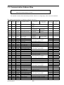
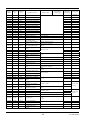
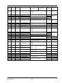
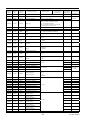
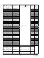
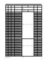
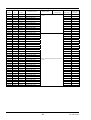
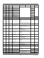
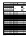
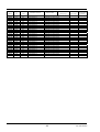
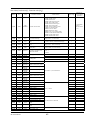
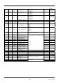
7.2 Communication Address Map
Caution: Never write data into addresses which are not disclosed to users.
Otherwise a failure may be caused.
For detailed contents about individual parameter function or setting range, refer to the user's manual.
Word data [read-out/write-in] : Function code [03H, 06H, 10H]
Relative
address
Register
No.
Parameter
name
0000H
40001
REM1
Remote mode
0: Auto
1: Remote
0010H
40017
STBY
Standby command
0: OFF
1: ON
0014H
40021
AT
Auto tuning command
0: AT Not activated
1: AT Activated
0: AT Stop
1: AT Execute
0020H
40033
LACH
Alarm unlatch command
0: Latched
1: Unlatched
0: No effect
1: Unlatch
0030H
0040H
40049
40065
PLTN
LOC
Palette signal selection
Key lock
0060H
40097
RES
Reset command
0100H
0100H
0102H
0104H
0106H
0108H
010AH
0110H
0110H
0112H
0114H
0116H
0118H
011AH
0120H
0120H
0122H
0124H
0126H
0128H
012AH
0130H
0130H
0132H
0134H
0136H
0138H
013AH
40257
40257
40259
40261
40263
40265
40267
40273
40273
40275
40277
40279
40281
40283
40289
40289
40291
40293
40295
40297
40299
40305
40305
40307
40309
40311
40313
40315
AL1
A1-L
A1-H
1 TP
1 OP
1HYS
1DLY
AL2
A2-L
A2-H
2 TP
2 OP
2HYS
2DLY
AL3
A3-L
A3-H
3 TP
3 OP
3HYS
3DLY
AL4
A4-L
A4-H
4 TP
4 OP
4HYS
4DLY
Alarm 1 setting
Alarm 1 low limit setting
Alarm 1 high limit setting
Alarm 1 type
Alarm 1 option
Alarm 1 hysteresis
Alarm 1 delay time
Alarm 2 setting
Alarm 2 low limit setting
Alarm 2 high limit setting
Alarm 2 type
Alarm 2 option
Alarm 2 hysteresis
Alarm 2 delay time
Alarm 3 setting
Alarm 3 low limit setting
Alarm 3 high limit setting
Alarm 3 type
Alarm 3 option
Alarm 3 hysteresis
Alarm 3 delay time
Alarm 4 setting
Alarm 4 low limit setting
Alarm 4 high limit setting
Alarm 4 type
Alarm 4 option
Alarm 4 hysteresis
Alarm 4 delay time
0140H
0140H
0142H
0144H
0146H
0148H
014AH
40321
40321
40323
40325
40327
40329
40331
AL5
A5-L
A5-H
5 TP
5 OP
5HYS
5DLY
Alarm 5 setting
Alarm 5 low limit setting
Alarm 5 high limit setting
Alarm 5 type
Alarm 5 option
Alarm 5 hysteresis
Alarm 5 delay time
INP-TN514207a-E
Parameter contents
Read-out data
Write-in data
setting range
0 to 7
0 to 5
0: Operating
0: No effect
normally
1: Execute resetting
1: Being reset
▪ Engineering unit setting
Absolute value alarm: 0 to 100%FS
Deviation alarm: –100 to 100%FS
0 to 11, 16 to 32, 35 to 38
0 to 15 (0000B to 1111B)
▪ Engineering unit setting (0 to 50%FS)
0 to 9999 (sec or min)
▪ Engineering unit setting
Absolute value alarm: 0 to 100%FS
Deviation alarm: –100 to 100%FS
0 to 11, 16 to 32, 35 to 38
0 to 15 (0000B to 1111B)
▪ Engineering unit setting (0 to 50%FS)
0 to 9999 (sec or min)
▪ Engineering unit setting
Absolute value alarm: 0 to 100%FS
Deviation alarm: –100 to 100%FS
0 to 11, 16 to 32, 35 to 38
0 to 15 (0000B to 1111B)
▪ Engineering unit setting (0 to 50%FS)
0 to 9999 (sec or min)
▪ Engineering unit setting
Absolute value alarm: 0 to 100%FS
Deviation alarm: –100 to 100%FS
0 to 11, 16 to 32, 35 to 38
0 to 15 (0000B to 1111B)
▪ Engineering unit setting (0 to 50%FS)
0 to 9999 (sec or min)
▪ Engineering unit setting
Absolute value alarm: 0 to 100%FS
Deviation alarm: –100 to 100%FS
0 to 11, 16 to 32, 35 to 38
0 to 15 (0000B to 1111B)
▪ Engineering unit setting (0 to 50%FS)
0 to 9999 (sec or min)
29
Affected by
input range
*
*
*
*
*
*
*
*
*
*
*
*
*
*
*
*
*
*
*
*
Remarks or
corresponding
parameter
Relative
address
Register
No.
Parameter
name
0150H
0150H
0152H
0154H
0156H
0158H
015AH
0160H
0160H
0162H
0164H
0166H
0168H
016AH
0170H
0170H
0172H
0174H
0176H
0178H
017AH
40337
40337
40339
40341
40343
40345
40347
40353
40353
40355
40357
40359
40361
40363
40369
40369
40371
40373
40375
40377
40379
AL6
A6-L
A6-H
6 TP
6 OP
6HYS
6DLY
AL7
A7-L
A7-H
7 TP
7 OP
7HYS
7DLY
AL8
A8-L
A8-H
8 TP
8 OP
8HYS
8DLY
0210H
40529
EXM1
0250H
40593
0280H
0282H
0284H
0286H
40641
40643
40645
40647
COMRSV
SV_L1
P1
I1
D1
028AH
40651
ARH1
028CH
40653
ARL1
028EH
0290H
0292H
0294H
0296H
0298H
40655
40657
40659
40661
40663
40665
SH1
SL1
MVH1
MVL1
hC1
LC1
029AH
40667
DMV1
029CH
029EH
40669
40671
DT1
HS1
02A4H
40677
BAL1
02A6H
40679
TC1
02A8H
40681
REV1
02ACH
40685
PMV1
02C6H
02C8H
40711
40713
hC2
LC2
0340H
40833
ALP1
0348H
40841
BET1
0350H
0352H
40849
40851
KF1
B1F1
0354H
40853
B2F1
0368H
40873
Manual
MV1
Parameter contents
Alarm 6 setting
Alarm 6 low limit setting
Alarm 6 high limit setting
Alarm 6 type
Alarm 6 option
Alarm 6 hysteresis
Alarm 6 delay time
Alarm 7 setting
Alarm 7 low limit setting
Alarm 7 high limit setting
Alarm 7 type
Alarm 7 option
Alarm 7 hysteresis
Alarm 7 delay time
Alarm 8 setting
Alarm 8 low limit setting
Alarm 8 high limit setting
Alarm 8 type
Alarm 8 option
Alarm 8 hysteresis
Alarm 8 delay time
External manipulation
variable setting
Communication via remote
setting
Local SV
Proportional band
Integral time
Derivative time
Anti-reset windup high limit
setting
Anti-reset windup low limit
setting
SV high limit
SV low limit
MV high limit setting
MV low limit setting
MV high limit setting (cool)
MV low limit setting (cool)
MV change ratio limit
setting
Sampling rate
Hysteresis setting
Manipulating output
convergence value
Control output (MV1)
proportional period
Control action setting
Manipulating output preset
value
MV high limit setting (cool)
MV low limit setting (cool)
2 degrees of freedom
coefficient α
2 degrees of freedom
coefficient β
Sets Feed Forward Gain and
bias 1, bias 2.
[FF=KF1 × (Input − B1F) +
B2F]
Read-out data
Write-in data
setting range
▪ Engineering unit setting
Absolute value alarm: 0 to 100%FS
Deviation alarm: –100 to 100%FS
0 to 11, 16 to 32, 35 to 38
0 to 15 (0000B to 1111B)
▪ Engineering unit setting (0 to 50%FS)
0 to 9999 (sec or min)
▪ Engineering unit setting
Absolute value alarm: 0 to 100%FS
Deviation alarm: –100 to 100%FS
0 to 11, 16 to 32, 35 to 38
0 to 15 (0000B to 1111B)
▪ Engineering unit setting (0 to 50%FS)
0 to 9999 (sec or min)
▪ Engineering unit setting
Absolute value alarm: 0 to 100%FS
Deviation alarm: –100 to 100%FS
0 to 11, 16 to 32, 35 to 38
0 to 15 (0000B to 1111B)
▪ Engineering unit setting (0 to 50%FS)
0 to 9999 (sec or min)
Affected by
input range
Remarks or
corresponding
parameter
*
*
*
*
*
*
*
*
*
*
*
*
–250 to 1250 (–25.0 to 125.0%)
▪ Engineering unit setting (0 to 100%FS)
▪ Engineering unit setting (–25 to 125%FS)
0 to 9999 (0.0 to 999.9%)
0 to 32000 (0.0 to 3200.0sec)
0 to 9999 (0.0 to 999.9sec)
*
*
▪ Engineering unit setting (0 to 100%FS)
*
▪ Engineering unit setting (–25 to 125%FS)
*
*
–250 to 1250 (–25.0 to 125.0%)
–25.0 to 125.0%
0 to 1500 (0.0 to 150.0%)
5 to 1000 (50 to 10000msec)
▪ Engineering unit setting (0 to 50%FS)
*
–1000 to 1000 (–100.0 to 100.0%)
1 to 150sec
0: NRML
1: REV
Turn off and
on power
–250 to 1250 (–25.0 to 125.0%)
–25.0 to 125.0%
–3000 to 3000 (–300.0 to 300.0%)
0 to 9999 (0.0 to 999.9%)
–10000 to 10000
0.0 to 100.0%
30
INP-TN514207a-E
Relative
address
Register
No.
Parameter
name
0400H
0402H
0404H
0406H
41025
41027
41029
41031
SV1
P-1
I-1
D-1
040AH
41035
ARH1
Parameter contents
0414H
41045
BL-1
0416H
41047
REF1
Set value 1
Pallet 1 proportional band
Pallet 1 integral time
Pallet 1 derivative time
Pallet 1 anti-reset windup
high limit
Pallet 1 anti-reset windup
low limit
Pallet 1 hysteresis setting
Pallet 1 output convergence
value
Pallet 1 PID change point
0418H
041AH
041CH
41049
41051
41053
PC-1
iC-1
dC-1
Cooling proportional band
Cooling integral time
Cooling derivative time
040CH
41037
ARL1
040EH
41039
HYS1
INP-TN514207a-E
Read-out data
Write-in data
setting range
▪ Engineering unit setting (–25 to 125%FS)
0 to 9999 (0.0 to 999.9%)
0 to 32000 (0.0 to 3200.0sec)
0 to 9999 (0.0 to 999.9sec)
0.0 to 999.9%
0.0 to 3200.0 sec
0.0 to 999.9 sec
Affected by
input range
*
*
▪ Engineering unit setting (0 to 100%FS)
*
▪ Engineering unit setting (0 to 50%FS)
*
–1000 to 1000 (–100.0 to 100.0%)
▪ Engineering unit setting (–25 to 125%FS)
31
*
Remarks or
corresponding
parameter
Relative
address
Register
No.
Parameter
name
0420H
0422H
0424H
0426H
41057
41059
41061
41063
SV2
P-2
I-2
D-2
042AH
41067
ARH2
042CH
41069
ARL2
042EH
41071
HYS2
0434H
41077
BL-2
0436H
0438H
043AH
043CH
41079
41081
41083
41085
REF2
PC-2
iC-2
dC-2
0440H
0442H
0444H
0446H
41089
41091
41093
41095
SV3
P-3
I-3
D-3
044AH
41099
ARH3
044CH
41101
ARL3
044EH
41103
HYS3
0454H
41109
BL-3
0456H
0458H
045AH
045CH
41111
41113
41115
41117
REF3
PC-3
iC-3
dC-3
0460H
0462H
0464H
0466H
41121
41123
41125
41127
SV4
P-4
I-4
D-4
046AH
41131
ARH4
046CH
41133
ARL4
046EH
41135
HYS4
0474H
41141
BL-4
0476H
0478H
047AH
047CH
41143
41145
41147
41149
REF4
PC-4
iC-4
dC-4
0480H
0482H
0484H
0486H
41153
41155
41157
41159
SV5
P-5
I-5
D-5
048AH
41163
ARH5
Parameter contents
Read-out data
Write-in data
setting range
Affected by
input range
Set value 2
Pallet 2 proportional band
Pallet 2 integral time
Pallet 2 derivative time
Pallet 2 anti-reset windup
high limit
Pallet 2 anti-reset windup low
limit
Pallet 2 hysteresis setting
Pallet 2 output convergence
value
Pallet 2 PID change point
Cooling proportional band
Cooling integral time
Cooling derivative time
▪ Engineering unit setting (–25 to 125%FS)
0 to 9999 (0.0 to 999.9%)
0 to 32000 (0.0 to 3200.0sec)
0 to 9999 (0.0 to 999.9sec)
▪ Engineering unit setting (–25 to 125%FS)
0.0 to 999.9%
0.0 to 3200.0 sec
0.0 to 999.9 sec
*
Set value 3
Pallet 3 proportional band
Pallet 3 integral time
Pallet 3 derivative time
Pallet 3 anti-reset windup
high limit
Pallet 3 anti-reset windup low
limit
Pallet 3 hysteresis setting
Pallet 3 output convergence
value
Pallet 3 PID change point
Cooling proportional band
Cooling integral time
Cooling derivative time
▪ Engineering unit setting (–25 to 125%FS)
0 to 9999 (0.0 to 999.9%)
0 to 32000 (0.0 to 3200.0sec)
0 to 9999 (0.0 to 999.9sec)
*
▪ Engineering unit setting (–25 to 125%FS)
0.0 to 999.9%
0.0 to 3200.0 sec
0.0 to 999.9 sec
*
Set value 4
Pallet 4 proportional band
Pallet 4 integral time
Pallet 4 derivative time
Pallet 4 anti-reset windup
high limit
Pallet 4 anti-reset windup low
limit
Pallet 4 hysteresis setting
Pallet 4 output convergence
value
Pallet 4 PID change point
Cooling proportional band
Cooling integral time
Cooling derivative time
▪ Engineering unit setting (–25 to 125%FS)
0 to 9999 (0.0 to 999.9%)
0 to 32000 (0.0 to 3200.0sec)
0 to 9999 (0.0 to 999.9sec)
*
▪ Engineering unit setting (–25 to 125%FS)
0.0 to 999.9%
0.0 to 3200.0 sec
0.0 to 999.9 sec
*
▪ Engineering unit setting (–25 to 125%FS)
0 to 9999 (0.0 to 999.9%)
0 to 32000 (0.0 to 3200.0sec)
0 to 9999 (0.0 to 999.9sec)
*
▪ Engineering unit setting (–25 to 125%FS)
0.0 to 999.9%
0.0 to 3200.0 sec
0.0 to 999.9 sec
*
▪ Engineering unit setting (–25 to 125%FS)
0 to 9999 (0.0 to 999.9%)
*
048CH
41165
ARL5
048EH
41167
HYS5
0494H
41173
BL-5
0496H
0498H
049AH
049CH
41175
41177
41179
41181
REF5
PC-5
iC-5
dC-5
Set value 5
Pallet 5 proportional band
Pallet 5 integral time
Pallet 5 derivative time
Pallet 5 anti-reset windup
high limit
Pallet 5 anti-reset windup low
limit
Pallet 5 hysteresis setting
Pallet 5 output convergence
value
Pallet 5 PID change point
Cooling proportional band
Cooling integral time
Cooling derivative time
04A0H
04A2H
41185
41187
SV6
P-6
Set value 6
Pallet 6 proportional band
Remarks or
correspondin
g
parameter
*
*
▪ Engineering unit setting (0 to 100%FS)
*
▪ Engineering unit setting (0 to 50%FS)
*
–1000 to 1000 (–100.0 to 100.0%)
*
▪ Engineering unit setting (0 to 100%FS)
*
▪ Engineering unit setting (0 to 50%FS)
*
–1000 to 1000 (–100.0 to 100.0%)
*
▪ Engineering unit setting (0 to 100%FS)
*
▪ Engineering unit setting (0 to 50%FS)
*
–1000 to 1000 (–100.0 to 100.0%)
*
▪ Engineering unit setting (0 to 100%FS)
*
▪ Engineering unit setting (0 to 50%FS)
*
–1000 to 1000 (–100.0 to 100.0%)
32
INP-TN514207a-E
Relative
address
Register
No.
Parameter
name
04A4H
04A6H
41189
41191
I-6
D-6
04AAH
41195
ARH6
04ACH
41197
ARL6
04AEH
41199
HYS6
04B4H
41205
BL-6
04B6H
04B8H
04BAH
04BCH
41207
41209
41211
41213
REF6
PC-6
iC-6
dC-6
04C0H
04C2H
04C4H
04C6H
41217
41219
41221
41223
SV7
P-7
I-7
D-7
04CAH
41227
ARH7
Parameter contents
Pallet 6 integral time
Pallet 6 derivative time
Pallet 6 anti-reset windup
high limit
Pallet 6 anti-reset windup low
limit
Pallet 6 hysteresis setting
Pallet 6 output convergence
value
Pallet 6 PID change point
Cooling proportional band
Cooling integral time
Cooling derivative time
04CCH
41229
ARL7
04CEH
41231
HYS7
04D4H
41237
BL-7
04D6H
04D8H
04DAH
04DCH
41239
41241
41243
41245
REF7
PC-7
iC-7
dC-7
Set value 7
Pallet 7 proportional band
Pallet 7 integral time
Pallet 7 derivative time
Pallet 7 anti-reset windup
high limit
Pallet 7 anti-reset windup low
limit
Pallet 7 hysteresis setting
Pallet 7 output convergence
value
Pallet 7 PID change point
Cooling proportional band
Cooling integral time
Cooling derivative time
04E0H
04E2H
04E4H
04E6H
04E8H
04EAH
04ECH
04EEH
04F0H
04F2H
04F4H
04F6H
04F8H
04FAH
04FCH
04FEH
0500H
0502H
0504H
0506H
0508H
050AH
050CH
050EH
0510H
0512H
0514H
0516H
0518H
051AH
051CH
41249
41251
41253
41255
41257
41259
41261
41263
41265
41267
41269
41271
41273
41275
41277
41279
41281
41283
41285
41287
41289
41291
41293
41295
41297
41299
41301
41303
41305
41307
41309
Mh-1
ML-1
hC-1
LC-1
Mh-2
ML-2
hC-2
LC-2
Mh-3
ML-3
hC-3
LC-3
Mh-4
ML-4
hC-4
LC-4
Mh-5
ML-5
hC-5
LC-5
Mh-6
ML-6
hC-6
LC-6
Mh-7
ML-7
hC-7
LC-7
hh-1
Lh-1
hh-2
MV high limit setting
MV low limit setting
MV high limit setting (cool)
MV low limit setting (cool)
MV high limit setting
MV low limit setting
MV high limit setting (cool)
MV low limit setting (cool)
MV high limit setting
MV low limit setting
MV high limit setting (cool)
MV low limit setting (cool)
MV high limit setting
MV low limit setting
MV high limit setting (cool)
MV low limit setting (cool)
MV high limit setting
MV low limit setting
MV high limit setting (cool)
MV low limit setting (cool)
MV high limit setting
MV low limit setting
MV high limit setting (cool)
MV low limit setting (cool)
MV high limit setting
MV low limit setting
MV high limit setting (cool)
MV low limit setting (cool)
MV high limit setting (heat)
MV low limit setting (heat)
MV high limit setting (heat)
INP-TN514207a-E
Read-out data
Write-in data
setting range
Affected by
input range
0 to 32000 (0.0 to 3200.0sec)
0 to 9999 (0.0 to 999.9sec)
*
▪ Engineering unit setting (0 to 100%FS)
*
▪ Engineering unit setting (0 to 50%FS)
*
–1000 to 1000 (–100.0 to 100.0%)
▪ Engineering unit setting (–25 to 125%FS)
0.0 to 999.9%
0.0 to 3200.0 sec
0.0 to 999.9 sec
*
▪ Engineering unit setting (–25 to 125%FS)
0 to 9999 (0.0 to 999.9%)
0 to 32000 (0.0 to 3200.0sec)
0 to 9999 (0.0 to 999.9sec)
*
*
▪ Engineering unit setting (0 to 100%FS)
*
▪ Engineering unit setting (0 to 50%FS)
*
–1000 to 1000 (–100.0 to 100.0%)
▪ Engineering unit setting (–25 to 125%FS)
0.0 to 999.9%
0.0 to 3200.0 sec
0.0 to 999.9 sec
-25.0 to 125.0%
33
*
Remarks or
correspondin
g
parameter
Relative
address
Register
No.
Parameter
name
051EH
0520H
0522H
0524H
0526H
0528H
052AH
052CH
052EH
0530H
0532H
0700H
0702H
0704H
41311
41313
41315
41317
41319
41321
41323
41325
41327
41329
41331
41793
41795
41797
Lh-2
hh-3
Lh-3
hh-4
Lh-4
hh-5
Lh-5
hh-6
Lh-6
hh-7
Lh-7
PC1
iC1
dC1
0706H
41799
TCC1
0708H
41801
rVC1
070AH
41803
MKC1
070CH
41805
PMC1
070EH
0710H
0712H
41807
41809
41811
hh1
Lh1
Ld1
0714H
41813
LdC1
0720H
0722H
0724H
41825
41827
41829
PC2
iC2
dC2
0726H
41831
TCC2
0728H
41833
rVC2
072AH
41835
MKC2
072CH
41837
PMC2
072EH
0730H
0732H
41839
41841
41843
hh2
Lh2
Ld2
0734H
41845
LdC2
0820H
42081
UCF1
0822H
42083
UCB1
0824H
42085
UCD1
0830H
0832H
0834H
0836H
42097
42099
42101
42103
PV1F
PV1B
PV1D
PV1T
Manipulating output value
(cool)
MV high limit setting (heat)
MV low limit setting (heat)
Output limiter type setting
Cooling output limiter type
setting
Mathematical calculation
full scale
Mathematical calculation
base scale
Mathematical calculation
decimal point position
PV1 full scale
PV1 base scale
PV1 decimal point position
PV1 input type
0838H
42105
PV1U
PV1 input unit
083AH
083CH
0844H
42107
42109
42117
PV1Z
PV1S
P1CU
0846H
42119
P1TF
PV1 zero adjustment
PV1 span adjustment
PV1 input router cut point
PV1 input filter time
constant
Parameter contents
MV low limit setting (heat)
MV high limit setting (heat)
MV low limit setting (heat)
MV high limit setting (heat)
MV low limit setting (heat)
MV high limit setting (heat)
MV low limit setting (heat)
MV high limit setting (heat)
MV low limit setting (heat)
MV high limit setting (heat)
MV low limit setting (heat)
Cooling proportional band
Cooling integral time
Cooling derivative time
Control output (cool)
proportional period
Control operation method
(cool)
MV output method (cool)
Manipulating output value
(cool)
MV high limit setting (heat)
MV low limit setting (heat)
Output limiter type setting
Cooling output limiter type
setting
Cooling proportional band
Cooling integral time
Cooling derivative time
Control output (cool)
proportional period
Control operation method
(cool)
MV output method (cool)
Read-out data
Write-in data
setting range
Affected by
input range
Remarks or
correspondin
g
parameter
-25.0 to 125.0%
0.0 to 999.9%
0.0 to 3200.0 sec
0.0 to 999.9 sec
1 to 150 sec
NRML: Normal operation
REV: Reverse operation
LNR
SSR-d
-25.0 to 125.0%
0 to 3
0.0 to 999.9%
0.0 to 3200.0 sec
0.0 to 999.9 sec
1 to 150 sec
NRML: Normal operation
REV: Reverse operation
LNR
SSR-d
-25.0 to 125.0%
0 to 3
–19999 to 99999
Turn off and
on power
0 to 3
–19999 to 99999
Turn off and
on power
0 to 3
0 to 9, 12 to 14, 16 to 20, 26, 27
0: °C
1: °F
2: non
▪ Engineering unit setting (–50 to 50%FS)
*
*
–1 to 1250 (–0.1 to 125.0%) (–1: OFF)
0 to 9000 (0.0 to 900.0sec)
34
INP-TN514207a-E
Relative
address
Register
No.
Parameter
name
0848H
42121
P1Ln
PV1 linearize setting
0850H
0852H
0854H
0856H
42129
42131
42133
42135
PV2F
PV2B
PV2D
PV2T
PV2 full scale
PV2 base scale
PV2 decimal point position
PV2 input type
0858H
42137
PV2U
PV2 input unit
085AH
085CH
0864H
42139
42141
42149
PV2Z
PV2S
P2CU
–1 to 1250 (–0.1 to 125.0%) (–1: OFF)
0866H
42151
P2TF
PV2 zero adjustment
PV2 span adjustment
PV2 input router cut point
PV2 input filter time
constant
(0) OFF
(1) nrML
(2) hi-C
(3) Lo-C
Parameter contents
0868H
42153
P2Ln
PV2 linearize setting
0890H
0892H
0894H
0896H
089AH
089CH
08A2H
42193
42195
42197
42199
42203
42205
42211
AI1F
AI1B
AI1D
AI1T
AI1Z
AI1S
A1CU
08A4H
42213
A1TF
AI1 full scale
AI1 base scale
AI1 decimal point position
AI1 input unit
AI1 zero adjustment
AI1 span adjustment
AI1 input router cut point
AI1 input filter time
constant
08A6H
42215
A1Ln
Ai1 linearize setting
0970H
42417
AO1T
AO1 output type
0972H
42419
AO2T
AO2 output type
0982H
42435
AO1L
AO1 output base scale
0984H
42437
AO1H
AO1 output full scale
0986H
0988H
0992H
0994H
0996H
0998H
42439
42441
42451
42453
42455
42457
A1LL
A1LH
AO2L
AO2H
A2LL
A2LH
AO1 output low limit
AO1 output high limit
AO2 output base scale
AO2 output full scale
AO2 output low limit
AO2 output high limit
INP-TN514207a-E
Read-out data
Write-in data
setting range
Affected by
input range
Remarks or
correspondin
g
parameter
(0) OFF
(1) nrML
(2) hi-C
(3) Lo-C
–19999 to 99999
Turn off and
on power
0 to 3
0 to 9, 12 to 14, 16 to 20, 26, 27
0: °C
1: °F
2: non
▪ Engineering unit setting (–50 to 50%FS)
*
*
0 to 9000 (0.0 to 900.0sec)
–19999 to 99999
Turn off and
on power
0 to 3
16 to 18
▪ Engineering unit setting (–50 to 50%FS)
–1 to 1250 (–0.1 to 125.0%) (–1: OFF)
0 to 9000 (0.0 to 900.0sec)
(0) OFF
(1) nrML
(2) hi-C
(3) Lo-C
1: PV
5: AiM
2: SV
6: S1
3: MV
7: S2
4: DV
8: S3
–1300 to 1300
(–130.0 to 130.0%)
–1300 to 1300
(–130.0 to 130.0%)
–250 to 1050 (–25.0 to 105.0%)
–1300 to 1300
(–130.0 to 130.0%)
–250 to 1050 (–25.0 to 105.0%)
35
*
*
Relative
address
Register
No.
Parameter
name
0A00H
42561
CALC
Calculation
0A02H
42563
TPLT
Template number
0A04H
42565
OTYP
Output type number
0A22H
42595
VTYP
Valve type
0A24H
0A26H
42597
42599
TrVL
PGP
0A2CH
42605
AdPC
0 to 1048575 (00000H to FFFFFH)
0A2EH
42607
AdPO
Travel time
Valve dead zone
Valve close adjustment
value
Valve open adjustment
value
0A30H
42609
RIH1
Remote setting inhibition
0: OFF
1: ON
0A40H
42625
RAC1
Whether to use R-ACK or
not
0: inhibit
1: enable
0A50H
42641
A-M1
A/M mode
0: A–M
1: A
0A60H
42657
CND1
Power-ON starting mode
setting
0: Auto
1: Remote
2: Manual
0A74H
42677
STBO
Standby action setting
0, 1
0A80H
42689
TRK1
Whether to select tracking
or not
0: OFF
1: ON
0A90H
42705
PLTS
Palette change method
selection
0: PLTn
1: SV
2: PV
0A92H
0A94H
0A96H
42707
42709
42711
F1
F2
F3
User assign key 1 (F1)
User assign key 2 (F2)
User assign key 3 (F3)
0 to 27
0A98H
0A9AH
0A9CH
42713
42715
42717
JP1
JP2
JP3
Parameter jump setting 1
Parameter jump setting 2
Parameter jump setting 3
1-01 to Z-Z9
Burnout direction
designation (MV1)
0: HOLD
1: LO
2: UP
3: EXMV
0AA0H
42721
BRD1
0AE0H
0AE2H
0AE4H
0AE6H
0AE8H
0AEAH
0AECH
0AEEH
0AF0H
42785
42787
42789
42791
42793
42795
42797
42799
42801
DI01
DI02
DI03
DI04
DI11
DI12
DI13
DI14
DI15
0B00H
42817
Ci01
0B02H
42819
Ci02
0B04H
42821
Ci03
0B06H
42823
Ci04
0B08H
42825
Ci05
0B0AH
42827
Ci06
0B0CH
42829
Ci07
Parameter contents
DI1 function selection
DI2 function selection
DI3 function selection
DI4 function selection
DI11 function selection
DI12 function selection
DI13 function selection
DI14 function selection
DI15 function selection
Communication Di1
function setting
Communication Di2
function setting
Communication Di3
function setting
Communication Di4
function setting
Communication Di5
function setting
Communication Di6
function setting
Communication Di7
function setting
Read-out data
Write-in data
setting range
0 to 40
10, 11, 13, 14, 16, 30, 31, 33, 34, 50, 51, 53,
54
10 to 13, 30, 31, 50 to 55
FB (0): PFB control
FB-Sr (1): PFB + estimated control
Sr1 (2): Estimated control 1
Sr2 (3): Estimated control 2 (Valve fully
open when power is turned on)
50 to 3000 (5.0 to 300.0 sec)
50 to 1000 (0.5 to 100.0%)
Affected by
input range
Remarks or
corresponding
parameter
Turn off and
on power
0 to 1048575 (00000H to FFFFFH)
Refer to
parameter no.
setting
0 to 255
0 to 255
36
INP-TN514207a-E
Relative
address
Register
No.
Parameter
name
0B0EH
42831
Ci08
Communication Di8
function setting
0B24H
42853
dSPT
Operation display type
0B26H
42855
odSP
Operation display setting
0B30H
42865
brG1
Bar graph display type
INP-TN514207a-E
Parameter contents
Read-out data
Write-in data
setting range
0: Control output (MV)
1: Valve aperture feedback value (MVRB)
000 to 111
1: Show, 0: Hide
0-bit: PV/totalized value
1-bit: Value during totalizer/totalized value
2-bit: PV/AiM
NON (0): No display
MV (1): Control output
MVRB (2): Valve aperture feedback value
37
Affected by
input range
Remarks or
corresponding
parameter
Relative
address
Register
No.
Parameter
name
0B50H
0B52H
0B54H
0B56H
0B58H
0B5AH
0B5CH
0B5EH
0B60H
0B62H
0B64H
0B66H
0B68H
0B6AH
0B6CH
0B6EH
0B70H
0B72H
0B74H
0B76H
0B78H
0B7AH
0B7CH
0B7EH
0B80H
0B82H
0B84H
0B86H
0B88H
0B8AH
0B8CH
0B8EH
0B90H
0B92H
0B94H
0B96H
0B98H
0B9AH
0B9CH
0B9EH
0BA0H
0BA2H
0BA4H
0BA6H
0BA8H
0C00H
0C02H
0C04H
42897
42899
42901
42903
42905
42907
42909
42911
42913
42915
42917
42919
42921
42923
42925
42927
42929
42931
42933
42935
42937
42939
42941
42943
42945
42947
42949
42951
42953
42955
42957
42959
42961
42963
42965
42967
42969
42971
42973
42975
42977
42979
42981
42983
42985
43073
43075
43077
DS00
DS01
DS02
DS03
DS04
DS05
DS06
DS07
DS08
DS09
DS10
DS11
DS12
DS13
DS14
DS15
DS16
DS17
DS18
DS19
DS20
DS21
DS22
DS23
DS24
DS25
DS26
DS27
DS28
DS29
DS30
DS31
DS32
DS33
DS34
DS35
DS36
DS37
DS38
DS39
DS40
DS41
DS42
DS43
DS44
PAS1
PAS2
PAS3
Parameter mask 00
Parameter mask 01
Parameter mask 02
Parameter mask 03
Parameter mask 04
Parameter mask 05
Parameter mask 06
Parameter mask 07
Parameter mask 08
Parameter mask 09
Parameter mask 10
Parameter mask 11
Parameter mask 12
Parameter mask 13
Parameter mask 14
Parameter mask 15
Parameter mask 16
Parameter mask 17
Parameter mask 18
Parameter mask 19
Parameter mask 20
Parameter mask 21
Parameter mask 22
Parameter mask 23
Parameter mask 24
Parameter mask 25
Parameter mask 26
Parameter mask 27
Parameter mask 28
Parameter mask 29
Parameter mask 30
Parameter mask 31
Parameter mask 32
Parameter mask 33
Parameter mask 34
Parameter mask 35
Parameter mask 36
Parameter mask 37
Parameter mask 38
Parameter mask 39
Parameter mask 40
Parameter mask 41
Parameter mask 42
Parameter mask 43
Parameter mask 44
Security setting 1
Security setting 2
Security setting 3
0 to 65535 (0000H to FFFFH)
0C22H
43107
STN4
RS-485 station No.
0 to 255
0C24H
43109
SPD4
RS-485 communication
speed
0: 9.6k
1: 19.2k
2: 38.4k
0C26H
43111
BIT4
RS-485 bit format
0: 8N
1: 8O
2: 8E
0C30H
43121
SPD2
RS-232C communication
speed
0: 9.6k
1: 19.2k
2: 38.4k
Parameter contents
Read-out data
38
Write-in data
setting range
Affected by
input range
Remarks or
corresponding
parameter
Turn off and
on power
INP-TN514207a-E
Relative
address
Register
No.
Parameter
name
0C32H
43123
BIT2
0C50H
43153
-
0C80H
0C82H
0C84H
0C86H
0C88H
0C8AH
0C8CH
0C8EH
0C90H
0C92H
0C94H
0C96H
0C98H
0C9AH
0C9CH
0C9EH
0CA0H
0CA2H
0CA4H
0CA6H
0CA8H
0CAAH
0CACH
0CAEH
0CB0H
0CB2H
0CB4H
0CB6H
0CB8H
0CBAH
0CBCH
0CBEH
43201
43203
43205
43207
43209
43211
43213
43215
43217
43219
43221
43223
43225
43227
43229
43231
43233
43235
43237
43239
43241
43243
43245
43247
43249
43251
43253
43255
43257
43259
43261
43263
0CC0H
0CC2H
0CC4H
0CC6H
0CC8H
0CCAH
0CCCH
0CCEH
0CD0H
0CD2H
0CD4H
0CD6H
0CD8H
0CDAH
0CDCH
0CDEH
0CE0H
0CE2H
0CE4H
0CE6H
0CE8H
43265
43267
43269
43271
43273
43275
43277
43279
43281
43283
43285
43287
43289
43291
43293
43295
43297
43299
43301
43303
43305
INP-TN514207a-E
Parameter contents
Read-out data
Write-in data
setting range
RS-232C bit format
0: 8N
1: 8O
2: 8E
FIX command
0: Not writing in
1: Now writing in
memory
P1X0
P1X1
P1X2
P1X3
P1X4
P1X5
P1X6
P1X7
P1X8
P1X9
P1XA
P1XB
P1XC
P1XD
P1XE
P1XF
P1Y0
P1Y1
P1Y2
P1Y3
P1Y4
P1Y5
P1Y6
P1Y7
P1Y8
P1Y9
P1YA
P1YB
P1YC
P1YD
P1YE
P1YF
Linearize table P1X0
Linearize table P1X1
Linearize table P1X2
Linearize table P1X3
Linearize table P1X4
Linearize table P1X5
Linearize table P1X6
Linearize table P1X7
Linearize table P1X8
Linearize table P1X9
Linearize table P1XA
Linearize table P1XB
Linearize table P1XC
Linearize table P1XD
Linearize table P1XE
Linearize table P1XF
Linearize table P1Y0
Linearize table P1Y1
Linearize table P1Y2
Linearize table P1Y3
Linearize table P1Y4
Linearize table P1Y5
Linearize table P1Y6
Linearize table P1Y7
Linearize table P1Y8
Linearize table P1Y9
Linearize table P1YA
Linearize table P1YB
Linearize table P1YC
Linearize table P1YD
Linearize table P1YE
Linearize table P1YF
-25% to 125% FS (Engineering value of PV1
scale)
P2X0
P2X1
P2X2
P2X3
P2X4
P2X5
P2X6
P2X7
P2X8
P2X9
P2XA
P2XB
P2XC
P2XD
P2XE
P2XF
P2Y0
P2Y1
P2Y2
P2Y3
P2Y4
Linearize table P2X0
Linearize table P2X1
Linearize table P2X2
Linearize table P2X3
Linearize table P2X4
Linearize table P2X5
Linearize table P2X6
Linearize table P2X7
Linearize table P2X8
Linearize table P2X9
Linearize table P2XA
Linearize table P2XB
Linearize table P2XC
Linearize table P2XD
Linearize table P2XE
Linearize table P2XF
Linearize table P2Y0
Linearize table P2Y1
Linearize table P2Y2
Linearize table P2Y3
Linearize table P2Y4
0: No effect
1: Write-in request
-25% to 125% FS (Engineering value of PV2
scale)
39
Affected by
input range
Remarks or
corresponding
parameter
Relative
address
Register
No.
Parameter
name
0CEAH
0CECH
0CEEH
0CF0H
0CF2H
0CF4H
0CF6H
0CF8H
0CFAH
0CFCH
0CFEH
43307
43309
43311
43313
43315
43317
43319
43321
43323
43325
43327
P2Y5
P2Y6
P2Y7
P2Y8
P2Y9
P2YA
P2YB
P2YC
P2YD
P2YE
P2YF
Linearize table P2Y5
Linearize table P2Y6
Linearize table P2Y7
Linearize table P2Y8
Linearize table P2Y9
Linearize table P2YA
Linearize table P2YB
Linearize table P2YC
Linearize table P2YD
Linearize table P2YE
Linearize table P2YF
0D40H
0D42H
0D44H
0D46H
0D48H
0D4AH
0D4CH
0D4EH
0D50H
0D52H
0D54H
0D56H
0D58H
0D5AH
0D5CH
0D5EH
0D60H
0D62H
0D64H
0D66H
0D68H
0D6AH
0D6CH
0D6EH
0D70H
0D72H
0D74H
0D76H
0D78H
0D7AH
0D7CH
0D7EH
43393
43395
43397
43399
43401
43403
43405
43407
43409
43411
43413
43415
43417
43419
43421
43423
43425
43427
43429
43431
43433
43435
43437
43439
43441
43443
43445
43447
43449
43451
43453
43455
A1X0
A1X1
A1X2
A1X3
A1X4
A1X5
A1X6
A1X7
A1X8
A1X9
A1XA
A1XB
A1XC
A1XD
A1XE
A1XF
A1Y0
A1Y1
A1Y2
A1Y3
A1Y4
A1Y5
A1Y6
A1Y7
A1Y8
A1Y9
A1YA
A1YB
A1YC
A1YD
A1YE
A1YF
Linearize table A1X0
Linearize table A1X1
Linearize table A1X2
Linearize table A1X3
Linearize table A1X4
Linearize table A1X5
Linearize table A1X6
Linearize table A1X7
Linearize table A1X8
Linearize table A1X9
Linearize table A1XA
Linearize table A1XB
Linearize table A1XC
Linearize table A1XD
Linearize table A1XE
Linearize table A1XF
Linearize table A1Y0
Linearize table A1Y1
Linearize table A1Y2
Linearize table A1Y3
Linearize table A1Y4
Linearize table A1Y5
Linearize table A1Y6
Linearize table A1Y7
Linearize table A1Y8
Linearize table A1Y9
Linearize table A1YA
Linearize table A1YB
Linearize table A1YC
Linearize table A1YD
Linearize table A1YE
Linearize table A1YF
Parameter contents
Read-out data
Write-in data
setting range
Affected by
input range
Remarks or
corresponding
parameter
-25% to 125% FS (Engineering value of PV2
scale)
-25% to 125% FS (Engineering value of Ai1
scale)
40
INP-TN514207a-E
Relative
address
Register
No.
Parameter
name
0DC0H
43521
K01
0DC2H
43523
K02
0DC4H
43525
K03
0DC6H
43527
K04
0DC8H
43529
K05
0DCAH
43531
K06
0DCCH
43533
K07
0DCEH
43535
K08
0DD0H
43537
K09
0DD2H
43539
K10
0DD4H
43541
K11
0DD6H
43543
K12
0DD8H
43545
K13
0DDAH
43547
K14
0DDCH
43549
K15
0DDEH
43551
K16
0E00H
43585
0E20H
0E22H
0E24H
0E26H
0E30H
0E32H
0E34H
0E36H
0E38H
Parameter contents
Read-out data
Write-in data
setting range
Affected by
input range
Remarks or
corresponding
parameter
Mathematical calculation
constant 1
Mathematical calculation
constant 2
Mathematical calculation
constant 3
Mathematical calculation
constant 4
Mathematical calculation
constant 5
Mathematical calculation
constant 6
Mathematical calculation
constant 7
Mathematical calculation
constant 8
Mathematical calculation
constant 9
Mathematical calculation
constant 10
Mathematical calculation
constant 11
Mathematical calculation
constant 12
Mathematical calculation
constant 13
Mathematical calculation
constant 14
Mathematical calculation
constant 15
Mathematical calculation
constant 16
▪ Floating decimal point type
99999 to 0.0000
–0.001 to –9999
ATP1
Auto tuning type
0: NRML
1: LPV
43617
43619
43621
43623
43633
43635
43637
43639
43641
DO1
DO2
DO3
DO4
DO11
DO12
DO13
DO14
DO15
DO1 output designation
DO2 output designation
DO3 output designation
DO4 output designation
DO11 output designation
DO12 output designation
DO13 output designation
DO14 output designation
DO15 output designation
0 to 255
Turn off and
on power
0E70H
0E72H
0E74H
0E76H
0E78H
0E7AH
0E7CH
0E7EH
43697
43699
43701
43703
43705
43707
43709
43711
C1
C2
LDO1
LDO2
LDO3
LDO4
LDO5
LALM
0 to 255
Turn off and
on power
0EA0H
43745
CN01
0EA2H
43747
CN02
0EA4H
43749
CN03
0EA6H
43751
CN04
0EA8H
43753
CN05
0EAAH
43755
CN06
0EACH
43757
CN07
0EAEH
43759
CN08
LED C1 assign
LED C2 assign
LED DO1 assign
LED DO2 assign
LED DO3 assign
LED DO4 assign
LED DO5 assign
LED ALM assign
Constant 1 used for
template
Constant 2 used for
template
Constant 3 used for
template
Constant 4 used for
template
Constant 5 used for
template
Constant 6 used for
template
Constant 7 used for
template
Constant 8 used for
template
INP-TN514207a-E
–19999 to 99999
41
Relative
address
Register
No.
Parameter
name
0EB0H
43761
CN09
0EB2H
43763
CN10
0EB4H
43765
CN11
0EB6H
43767
CN12
0EB8H
43769
CN13
0EBAH
43771
CN14
0EBCH
43773
CN15
0EBEH
43775
CN16
0F00H
43841
TrUn
Constant 9 used for
template
Constant 10 used for
template
Constant 11 used for
template
Constant 12 used for
template
Constant 13 used for
template
Constant 14 used for
template
Constant 15 used for
template
Constant 16 used for
template
Totalizer command/status
0F02H
43843
TrES
Totalizer reset command
0F04H
43845
Toin
Totalizer input selection
0F06H
43847
TdP
Totalizer value display
decimal point position
Parameter contents
0F08H
43849
TCUT
Totalizer cut point
0F0AH
43851
A1TP
Totalizer alarm 1 type
0F0CH
43853
A1on
Totalizer alarm 1
ON pulse width
0F0EH
43855
A1oP
Totalizer alarm 1
Excitation/non-excitation
setting
0F10H
43857
A2TP
Totalizer alarm 2 type
0F12H
43859
A2on
Totalizer alarm 2
ON pulse width
0F14H
43861
A2oP
Totalizer alarm 2
Excitation/non-excitation
setting
0F16H
43863
TMod
Operation mode
0F18H
43865
ToPT
Totalizer option setting
0F1AH
43867
Tb
Totalizer standard time
0F1CH
43869
SCL
Totalizer divisor
0F1EH
43871
MUL
Totalizer multiplier
0F20H
43873
TCF
Totalizer constant
0F22H
43875
TinT
Totalizer initial value
0F24H
43877
A1SP
Totalizer alarm 1 setting
Read-out data
Write-in data
setting range
Affected by
input range
Remarks or
corresponding
parameter
hoLd/rUn/LATCh
on/oFF
(0) Pv1
(1) Pv2
(2) Ai1
(3) AiM
* When “(3) AiM” is selected, set the
mathematical calculation scale to (Ch 8-89,
90, 91).
0 to 4
0% to 100%FS
(Engineering value setting)
Decimal point position for the input scale set
in Toin depends on decimal point setting for
input range.
0: No alarm
1: Totalizer value alarm
2: Totalizer batch output
3: Totalizer batch output (with auto-reset)
0: Continuous
1: 100 ms
2: 200 ms
3: 500 ms
4: 1 sec
0: Excitation
1: Non-excitation
0: No alarm
1: Totalizer value alarm
2: Totalizer batch output
3: Totalizer batch output (with auto-reset)
0: Continuous
1: 100 ms
2: 200 ms
3: 500 ms
4: 1 sec
0: Excitation
1: Non-excitation
(0) JPn: Japanese mode
(1) EnG: English mode
0000 to 1111
(0) SEC
(1) Min
(2) hoUr
(3) dAY
0 to ±1000000
20 to 9999999
Uses decimal point set in TdP
-1999999 to 9999999
Uses decimal point set in TdP
42
INP-TN514207a-E
Relative
address
Register
No.
Parameter
name
0F26H
43879
A2SP
Totalizer alarm 2 setting
0F28H
43881
rTSc
Transfer output source scale
0F30H
43889
rCP0
Recipe assignment 1
0F32H
43891
rCP1
Recipe assignment 2
0F34H
43893
rCP2
Recipe assignment 3
0F36H
43895
rCP3
Recipe assignment 4
0F38H
43897
rCP4
Recipe assignment 5
Parameter contents
0F3AH
43899
rCP5
Recipe assignment 6
0F3CH
43901
rCP6
Recipe assignment 7
0F3EH
43903
rCP7
Recipe assignment 8
0F40H
43905
rCP8
Recipe assignment 9
0F42H
0F44H
0F46H
0F48H
0F4AH
0F4CH
0F4EH
0F50H
0F52H
0F54H
0F56H
0F58H
0F5AH
0F5CH
0F5EH
0F60H
0F62H
0F64H
0F66H
0F68H
0F6AH
0F6CH
0F6EH
0F70H
0F72H
0F74H
0F76H
0F78H
0F7AH
0F7CH
0F7EH
0F80H
0F82H
0F84H
0F86H
0F88H
0F8AH
0F8CH
0F8EH
0F90H
0F92H
0F94H
0F96H
0F98H
0F9AH
0F9CH
0F9EH
0FA0H
0FA2H
0FA4H
0FA6H
0FA8H
0FAAH
0FACH
0FAEH
43907
43909
43911
43913
43915
43917
43919
43921
43923
43925
43927
43929
43931
43933
43935
43937
43939
43941
43943
43945
43947
43949
43951
43953
43955
43957
43959
43961
43963
43965
43967
43969
43971
43973
43975
43977
43979
43981
43983
43985
43987
43989
43991
43993
43995
43997
43999
44001
44003
44005
44007
44009
44011
44013
44015
rCP9
d00
d01
d02
d03
d04
d05
d06
d07
d08
d09
d10
d11
d12
d13
d14
d15
d16
d17
d18
d19
d20
d21
d22
d23
d24
d25
d26
d27
d28
d29
d30
d31
d32
d33
d34
d35
d36
d37
d38
d39
d40
d41
d42
d43
d44
d45
d46
d47
d48
d49
d50
d51
d52
d53
Recipe assignment 10
Recipe setting 0
Recipe setting 1
Recipe setting 2
Recipe setting 3
Recipe setting 4
Recipe setting 5
Recipe setting 6
Recipe setting 7
Recipe setting 8
Recipe setting 9
Recipe setting 10
Recipe setting 11
Recipe setting 12
Recipe setting 13
Recipe setting 14
Recipe setting 15
Recipe setting 16
Recipe setting 17
Recipe setting 18
Recipe setting 19
Recipe setting 20
Recipe setting 21
Recipe setting 22
Recipe setting 23
Recipe setting 24
Recipe setting 25
Recipe setting 26
Recipe setting 27
Recipe setting 28
Recipe setting 29
Recipe setting 30
Recipe setting 31
Recipe setting 32
Recipe setting 33
Recipe setting 34
Recipe setting 35
Recipe setting 36
Recipe setting 37
Recipe setting 38
Recipe setting 39
Recipe setting 40
Recipe setting 41
Recipe setting 42
Recipe setting 43
Recipe setting 44
Recipe setting 45
Recipe setting 46
Recipe setting 47
Recipe setting 48
Recipe setting 49
Recipe setting 50
Recipe setting 51
Recipe setting 52
Recipe setting 53
INP-TN514207a-E
Read-out data
Write-in data
setting range
Affected by
input range
Remarks or
corresponding
parameter
-1999999 to 9999999
Uses decimal point set in TdP
-1999999 to 9999999
0-00 to R-Z9
Dependent on rCP0 setting
Dependent on rCP1 setting
Dependent on rCP2 setting
Dependent on rCP3 setting
Dependent on rCP4 setting
Dependent on rCP5 setting
Dependent on rCP6 setting
Dependent on rCP7 setting
Dependent on rCP8 setting
Dependent on rCP9 setting
Dependent on rCP0 setting
Dependent on rCP1 setting
Dependent on rCP2 setting
Dependent on rCP3 setting
Dependent on rCP4 setting
Dependent on rCP5 setting
Dependent on rCP6 setting
Dependent on rCP7 setting
Dependent on rCP8 setting
Dependent on rCP9 setting
Dependent on rCP0 setting
Dependent on rCP1 setting
Dependent on rCP2 setting
Dependent on rCP3 setting
Dependent on rCP4 setting
Dependent on rCP5 setting
Dependent on rCP6 setting
Dependent on rCP7 setting
Dependent on rCP8 setting
Dependent on rCP9 setting
Dependent on rCP0 setting
Dependent on rCP1 setting
Dependent on rCP2 setting
Dependent on rCP3 setting
Dependent on rCP4 setting
Dependent on rCP5 setting
Dependent on rCP6 setting
Dependent on rCP7 setting
Dependent on rCP8 setting
Dependent on rCP9 setting
Dependent on rCP0 setting
Dependent on rCP1 setting
Dependent on rCP2 setting
Dependent on rCP3 setting
Dependent on rCP4 setting
Dependent on rCP5 setting
Dependent on rCP6 setting
Dependent on rCP7 setting
Dependent on rCP8 setting
Dependent on rCP9 setting
Dependent on rCP0 setting
Dependent on rCP1 setting
Dependent on rCP2 setting
Dependent on rCP3 setting
43
Refer to
parameter no.
setting
Relative
address
Register
No.
Parameter
name
0FB0H
0FB2H
0FB4H
0FB6H
0FB8H
0FBAH
0FBCH
0FBEH
0FC0H
0FC2H
0FC4H
0FC6H
0FC8H
0FCAH
0FCCH
0FCEH
0FD0H
0FD2H
0FD4H
0FD6H
0FD8H
0FDAH
0FDCH
0FDEH
0FE0H
0FE2H
01388H
44017
44019
44021
44023
44025
44027
44029
44031
44033
44035
44037
44039
44041
44043
44045
44047
44049
44051
44053
44055
44057
44059
44061
44063
44065
44067
45001
d54
d55
d56
d57
d58
d59
d60
d61
d62
d63
d64
d65
d66
d67
d68
d69
d70
d71
d72
d73
d74
d75
d76
d77
d78
d79
Parameter contents
Recipe setting 54
Recipe setting 55
Recipe setting 56
Recipe setting 57
Recipe setting 58
Recipe setting 59
Recipe setting 60
Recipe setting 61
Recipe setting 62
Recipe setting 63
Recipe setting 64
Recipe setting 65
Recipe setting 66
Recipe setting 67
Recipe setting 68
Recipe setting 69
Recipe setting 70
Recipe setting 71
Recipe setting 72
Recipe setting 73
Recipe setting 74
Recipe setting 75
Recipe setting 76
Recipe setting 77
Recipe setting 78
Recipe setting 79
Communication Di terminal
Read-out data
Write-in data
setting range
Affected by
input range
Remarks or
corresponding
parameter
Dependent on rCP4 setting
Dependent on rCP5 setting
Dependent on rCP6 setting
Dependent on rCP7 setting
Dependent on rCP8 setting
Dependent on rCP9 setting
Dependent on rCP0 setting
Dependent on rCP1 setting
Dependent on rCP2 setting
Dependent on rCP3 setting
Dependent on rCP4 setting
Dependent on rCP5 setting
Dependent on rCP6 setting
Dependent on rCP7 setting
Dependent on rCP8 setting
Dependent on rCP9 setting
Dependent on rCP0 setting
Dependent on rCP1 setting
Dependent on rCP2 setting
Dependent on rCP3 setting
Dependent on rCP4 setting
Dependent on rCP5 setting
Dependent on rCP6 setting
Dependent on rCP7 setting
Dependent on rCP8 setting
Dependent on rCP9 setting
00000000 to 11111111 (8-bit)
44
INP-TN514207a-E
Word data [read-out only] : Function code [04H]
Relative
address
Register
No.
Parameter
name
Parameter contents
0100H
30257
PID
MODE1
0102H
30259
PV1
0104H
30261
SV1
0106H
30263
DV1
0108H
30265
MV1
010CH
30269
FAULT1
0270H
0272H
30625
30627
HMV1
HMV2
0280H
0282H
30641
30643
0310H
30785
0312H
30787
0314H
30789
0316H
30791
0318H
30793
031AH
30795
031CH
30797
031EH
30799
0340H
30833
CMV1
CMV2
ALM1
(RELAY)
ALM2
(RELAY)
ALM3
(RELAY)
ALM4
(RELAY)
ALM5
(RELAY)
ALM6
(RELAY)
ALM7
(RELAY)
ALM8
(RELAY)
ALM1
Alarm 1 status
0342H
30835
ALM2
Alarm 2 status
0344H
30837
ALM3
Alarm 3 status
0346H
30839
ALM4
Alarm 4 status
0348H
30841
ALM5
Alarm 5 status
Current control mode
Process variable (PV) used
for control currently
Currently used setpoint
(SV)
Currently used deviation
(DV)
Currently used manipulating
value (MV)
Affected by
input range
0001H: Fault status
0002H: Standby status
0004H: Remote Ack
0008H: Other than auto mode
0010H: Auto mode request
0020H: Remote mode request
0040H: Auto tuning status
0080H: Normal operation status
0100H: PV tracking status
0200H: Local SV status
0400H: Remote SV status
0800H: Local + PV tracking status
1000H: Forced manual mode status
2000H: EX-MV mode status
4000H: Manual mode status
*
–19999 to 99999 (within settable range)
*
–125998 to 125998
(Input scale: –105 to 105% FS)
*
–250 to 1250 (–25.0 to 125.0%)
Normal: 0
Over: 1
Under: 2
Heating MV
—
—
Cooling MV
—
—
Alarm 1 status (relay status)
Alarm 2 status (relay status)
Alarm 3 status (relay status)
Alarm 4 status (relay status)
Excitation: 1, Non-excitation: 0
Alarm 5 status (relay status)
Alarm 6 status (relay status)
Alarm 7 status (relay status)
Alarm 8 status (relay status)
30843
ALM6
Alarm 6 status
034CH
30845
ALM7
Alarm 7 status
034EH
30847
ALM8
0400H
0402H
0406H
31025
31027
31031
PV1
PV2
AI1
0420H
31057
RCJ1
0422H
31059
RCJ2
0450H
0452H
31105
31107
AO1
AO2
ON: 1, OFF: 0
Alarm 8 status
PV1 measurement value
PV2 measurement value
Ai1 measurement value
PV1 RCJ measurement
value
PV2 RCJ measurement
value
AO1 output value
AO2 output value
–214783647 to 214783648
–250 to 1250 (–25.0 to 125.0%)
45
Remarks or
corresponding
parameter
Correspondin
g bit to
relevant status
is "1".
–25999 to 105999
(Input scale: –5 to 105% FS)
Currently used input error
status information
034AH
INP-TN514207a-E
Read-out data
*
*
*
Relative
address
Register
No.
Parameter
name
Parameter contents
0470H
31137
DI01
DI1 to 4 input status
0472H
31139
DI11
DI11 to 15 input status
0476H
31143
diC1
0478H
31145
diC2
Communication Di monitor
(1-5)
Communication Di monitor
(6-8)
04D0H
31233
DO01
DO1 to 4 output status
04D2H
31235
DO11
DO11 to 15 output status
0540H
31345
AIM
Mathematical calculation
result
0550H
31361
0552H
31363
0554H
31365
0556H
31367
0558H
31369
055AH
31371
055CH
31373
055EH
31375
ALM
DLY 1
ALM
DLY 2
ALM
DLY 3
ALM
DLY 4
ALM
DLY 5
ALM
DLY 6
ALM
DLY 7
ALM
DLY 8
0564H
31381
AMV1
056CH
0574H
0576H
31389
31397
31399
FFV1
MVrb
Int Val
0578H
31401
057AH
31403
057CH
057EH
31405
31407
Alarm 1 delay timer
remaining time monitor
Alarm 2 delay timer
remaining time monitor
Alarm 3 delay timer
remaining time monitor
Alarm 4 delay timer
remaining time monitor
Alarm 5 delay timer
remaining time monitor
Alarm 6 delay timer
remaining time monitor
Alarm 7 delay timer
remaining time monitor
Alarm 8 delay timer
remaining time monitor
EXMV value
(External analog value)
Feed Forward value
Valve aperture monitor
Front integration display
Totalizer alarm 1 status
(relay state)
Totalizer alarm 2 status
(relay state)
Totalizer alarm 1 status
Totalizer alarm 2 status
Read-out data
Affected by
input range
DI1: 8000H
DI2: 4000H
DI3: 2000H
DI4: 1000H
DI11: 8000H
DI12: 4000H
DI13: 2000H
DI14: 1000H
DI15: 0800H
—
Remarks or
corresponding
parameter
Correspondin
g bit to ON is
"1".
Correspondin
g bit to ON is
"1".
—
DO1: 1
DO2: 2
DO3: 4
DO4: 8
DO11: 1
DO12: 2
DO13: 4
DO14: 8
DO15: 16
–214783647 to 214783648
Correspondin
g bit to ON is
"1".
Correspondin
g bit to ON is
"1".
*
Mathematical
calculation
scale
0 to 9999
–214783647 to 214783648
–214783647 to 214783648
-50 to 1050 (-5.0% to 105.0%)
Excitation: 1, Non-excitation: 0
ON: 1, OFF: 0
46
INP-TN514207a-E
8. SAMPLE PROGRAM
This section concerns data read-out/write-in sample program by Microsoft Visual Basic 6.0 (SP6) (enclosed
to CD-ROM).
Note that the program shown here is for reference for you to create a program and not for guaranteeing all
actions.
Before executing the program, make sure of the communication conditions in the following procedure.
▪ Parity, communication speed: Must be set in this program to match the instrument.
Precautions for some RS-232C ⇔ RS-485 converter
The transmission data itself may precede the answer data from the slave station. In such a case, discard
as many data as transmission bytes found there, and then process it as answer data.
Applicable OS
Windows 2000 Professional
Windows XP Professional Edition
Fuji Electric Systems Co., Ltd. will not be responsible for damages attributable to use of the sample program
nor infringement of rights owned by third parties.
Use the program upon admitting the above.
INP-TN514207a-E
47
(a) Example of data read-out
Operation: 2 word data of a designated address is read-out and displayed at a time.
Used function code: 03H , 04H
Read-out word number: 2
' Variable declaration ***************************************************************************************************************
Dim idx As Integer
Dim Ansdat() As Byte
' For storing answer data
Dim Rxbuff As Variant
' Receive data buffer
Dim PauseTime
' Sets the communication wait time
' Required wait time depends on transmission speed and transmission frame length
Dim Stno As Byte
' Communication station number
Private Sub Form_Load()
' Initializing the variable ************************************************************************************************************
Stno = 1
Main.Visible = True
End Sub
'-----------------------------------------'Read continuous words sample program
'Function code : 03H, 04H
'Number of words : 2
'-----------------------------------------Private Sub TX1_Click()
TX1.Enabled = False
' Communication port setting ********************************************************************************************************
If Com5.Value = True Then
Comm_port = 5
' COM5
ElseIf Com4.Value = True Then
Comm_port = 4
' COM4
ElseIf Com3.Value = True Then
Comm_port = 3
' COM3
ElseIf Com2.Value = True Then
Comm_port = 2
' COM2
Else
Comm_port = 1
' COM1
End If
If SPD192.Value = True Then
Comm_speed = "19200,"
ElseIf SPD96.Value = True Then
Comm_speed = "9600,"
Else
Comm_speed = "38400,"
End If
If Even1.Value = True Then
Comm_parity = "E,"
ElseIf Odd1.Value = True Then
Comm_parity = "O,"
Else
Comm_parity = "N,"
End If
PauseTime = 0.2
' 19200bps
' 9600bps
' 38400bps
' Even parity
' Odd parity
' No parity
' Sets the wait time (0.2 sec)
idx = 0
' Opening the communication port ****************************************************************************************************
MSComm1.CommPort = Comm_port
' COM port setting
MSComm1.Settings = Comm_speed & Comm_parity & "8,1"
' Speed / Party / 8bit_Data / Stop_1bit
MSComm1.PortOpen = True
' Opens a port
' Setting the opposite station number for communication **********************************************************************************
St = Val(Stno1(idx).Text)
Stno = St Mod 256
Stno1(idx).Text = Str(Stno)
' Address processing ***************************************************************************************************************
AD$ = Str(Val(Address(idx).Text) - 1)
AD$ = Right$(("00000" & AD$), 5)
Area = Val(Left$(AD$, 1))
Adrsh = Int(Val(Right$(AD$, 4)) / 256)
Adrsl = Val(Right$(AD$, 4)) Mod 256
48
INP-TN514207a-E
' Transmission command generation **************************************************************************************************
Select Case Area
Case 3
ReDim Txdat(7) As Byte
' Secures 8 byte array
Txdat(0) = Stno
' Station No.
Txdat(1) = &H4
' Command
Txdat(2) = Adrsh
' High address
Txdat(3) = Adrsl
' Low address
Txdat(4) = &H0
' Number of read-in words (High)
Txdat(5) = &H2
' Number of read-in words (Low)
Txsu = 5
' Number of transmission data
Case 4
ReDim Txdat(7) As Byte
Txdat(0) = Stno
Txdat(1) = &H3
Txdat(2) = Adrsh
Txdat(3) = Adrsl
Txdat(4) = &H0
Txdat(5) = &H2
Txsu = 5
Case Else
MSComm1.PortOpen = False
TX1.Enabled = True
Exit Sub
End Select
' Secures 8 byte array
' Station No.
' Command
' High address
' Low address
' Number of read-in words (High)
' Number of read-in words (Lo)
' Number of transmission data
' For other value
' Closes COM port
' Transmitting a command **********************************************************************************************************
' Generation of CRC for transmission data
GoSub 10000
Txdat(Txsu + 1) = CRC1
Txdat(Txsu + 2) = CRC2
' CRC calculation
'
'
' Transmitting a generated command
MSComm1.Output = Txdat
' Transmits 1 byte
' Waiting until all answer data is received
Start = Timer
' Saves the waiting start time
Do While Timer < Start + PauseTime
' Whether time setting elapsed
DoEvents
' Transfers the control to another process
If ((Start + PauseTime) - Timer) > PauseTime Then
Start = Timer
End If
Loop
' Fetching the answer data into byte array
MSComm1.InputMode = comInputModeBinary
length = MSComm1.InBufferCount
MSComm1.InputLen = 0
Rxbuff = MSComm1.Input
Ansdat = Rxbuff
' Designates binary mode
' Acquires required number of receive data bytes
' Designates acquisition of all data
' Fetches receive data into receive buffer
' Assigns byte array to receive data
' CRC calculation for receive data
Ansu = length – 3
GoSub 20000
' Receive data length
' CRC calculation
' Error check
If (length = 0) Then
Noans = Noans + 1: Rx_data.Caption = "Noans": GoTo 150
ElseIf ((Ansdat(length - 2) <> CRC1) + (Ansdat(length - 1) <> CRC2)) Then
CRCErr = CRCErr + 1: Rx_data.Caption = "CRCErr": GoTo 150
ElseIf Ansdat(1) >= &H80 Then
CMDErr = CMDErr + 1: Rx_data.Caption = "CMDErr": GoTo 150
End If
' No anser
' CRC error
' Command error
' Processing of normal receive data
wrk1 = Ansdat(3)
wrk2 = Ansdat(4)
wrk3 = Ansdat(5)
wrk4 = Ansdat(6)
If Ansdat(5) > 128 Then
' If receive data is negative
Rx_data.Caption = Str(((wrk3 * (2 ^ 24)) + (wrk4 * (2 ^ 16)) + (wrk1 * (2 ^ 8)) + wrk2) - (2 ^ 32))
Else
Rx_data.Caption = Str(((wrk3 * (2 ^ 24)) + (wrk4 * (2 ^ 16)) + (wrk1 * (2 ^ 8)) + wrk2))
End If
150
MSComm1.PortOpen = False
' Closes COM port
TX1.Enabled = True
Exit Sub
INP-TN514207a-E
49
' ******************************************************************************************************************************
10000
' CRC calculation subroutine IN:Txdat(Txsu) / OUT CRC1,CRC2 ***************************************************************
CRC = &HFFFF
For i = 0 To Txsu Step 1
CRC = CRC Xor Txdat(i)
For J = 1 To 8 Step 1
CT = CRC And &H1
If CRC < 0 Then CH = 1 Else: CH = 0: GoTo 11000
CRC = CRC And &H7FFF
11000
CRC = Int(CRC / 2)
If CH = 1 Then CRC = CRC Or &H4000
If CT = 1 Then CRC = CRC Xor &HA001
Next J
Next i
CRC1 = CRC And &HFF
CRC2 = ((CRC And &HFF00) / 256 And &HFF)
Return
20000
' CRC calculation subroutine IN:Ansdat(Ansu) / OUT CRC1,CRC2 **************************************************************
CRC = &HFFFF
For i = 0 To Ansu Step 1
CRC = CRC Xor Ansdat(i)
For J = 1 To 8 Step 1
CT = CRC And &H1
If CRC < 0 Then CH = 1 Else: CH = 0: GoTo 21000
CRC = CRC And &H7FFF
21000
CRC = Int(CRC / 2)
If CH = 1 Then CRC = CRC Or &H4000
If CT = 1 Then CRC = CRC Xor &HA001
Next J
Next i
CRC1 = CRC And &HFF
CRC2 = ((CRC And &HFF00) / 256 And &HFF)
Return
End Sub
50
INP-TN514207a-E
(b) Example of data write-in
Operation: Writes 2 word data into a designated address
Used function code: 10H
Number of write-in words: 2
'----------------------------------'Write 2 words sample program
'Function code : 10H
'Number of words : 2
'----------------------------------Private Sub Write_command_Click()
Write_command.Enabled = False
' Communication port setting ***************************************************************************************************
If Com5.Value = True Then
Comm_port = 5
' COM5
ElseIf Com4.Value = True Then
Comm_port = 4
' COM4
ElseIf Com3.Value = True Then
Comm_port = 3
' COM3
ElseIf Com2.Value = True Then
Comm_port = 2
' COM2
Else
Comm_port = 1
' COM1
End If
If SPD192.Value = True Then
Comm_speed = "19200,"
ElseIf SPD96.Value = True Then
Comm_speed = "9600,"
Else
Comm_speed = "38400,"
End If
If Even1.Value = True Then
Comm_parity = "E,"
ElseIf Odd1.Value = True Then
Comm_parity = "O,"
Else
Comm_parity = "N,"
End If
PauseTime = 0.2
idx = 1
' 19200bps
' 9600bps
' 38400bps
' Even parity
' Odd parity
' No parity
' Sets the wait time (0.2 sec)
' Opening the communication port ************************************************************************************************
MSComm1.CommPort = Comm_port
' Com port
MSComm1.Settings = Comm_speed & Comm_parity & "8,1"
' Speed / Party / 8bit_Data / Stop_1bit
MSComm1.PortOpen = True
' Open com port
' Setting the opposite station number for communication *******************************************************************************
St = Val(Stno1(idx).Text)
Stno = St Mod 256
Stno1(idx).Text = Str(Stno)
' Address processing ***********************************************************************************************************
AD$ = Str(Val(Address(idx).Text) - 1)
AD$ = Right$(("00000" & AD$), 5)
Area = Val(Left$(AD$, 1))
Adrsh = Int(Val(Right$(AD$, 4)) / 256)
Adrsl = Val(Right$(AD$, 4)) Mod 256
' Transmission command generation ***********************************************************************************************
Select Case Area
Case 4
'Normal sending data is processed.
Dim byteData(3) As Byte
Dim sHex As String
sHex = Right("00000000" & Hex(Val(Write_data.Text)), 8) ' Decimal → hexadecimal
byteData(0) = CByte("&H" & Mid(sHex, 1, 2))
'hh byte
byteData(1) = CByte("&H" & Mid(sHex, 3, 2))
'hl byte
byteData(2) = CByte("&H" & Mid(sHex, 5, 2))
'lh byte
byteData(3) = CByte("&H" & Mid(sHex, 7, 2))
'll byte
INP-TN514207a-E
51
ReDim Txdat(12) As Byte
Txdat(0) = Stno
Txdat(1) = &H10
Txdat(2) = Adrsh
Txdat(3) = Adrsl
Txdat(4) = &H0
Txdat(5) = &H2
Txdat(6) = &H4
Txdat(7) = byteData(2)
Txdat(8) = byteData(3)
Txdat(9) = byteData(0)
Txdat(10) = byteData(1)
Txsu = 10
Case Else
MSComm1.PortOpen = False
Write_command.Enabled = True
Exit Sub
End Select
' 13 bytes
' Station No.
' Command
' High address
' Low address
' Number of write-in words (High)
' Number of write -in words (Lo)
' Number of write -in bytes
' Write-in data (Lo high)
' Write-in data (Lo lo)
' Write-in data (High high)
' Write-in data (HIgh lo)
' Number of transmission data
' For other
' Closes COM port
' Transmitting a command ********************************************************************************************************
' Generation of CRC for transmission data
GoSub 10000
Txdat(Txsu + 1) = CRC1
Txdat(Txsu + 2) = CRC2
' CRC calculation
'
'
' Transmitting a generated command
MSComm1.Output = Txdat
' Transmits 1 byte
' Waiting until all answer data is received
Start = Timer
' Saves the waiting start time
Do While Timer < Start + PauseTime
' Whether time setting elapsed
DoEvents
' Transfers the control to another process
If ((Start + PauseTime) - Timer) > PauseTime Then
Start = Timer
End If
Loop
MSComm1.PortOpen = False
' Closes COM port
Write_command.Enabled = True
Exit Sub
' ********************************************************************************************************************************
10000
' CRC calculation subroutine IN:Txdat(Txsu) / OUT CRC1,CRC2 *****************************************************************
CRC = &HFFFF
For i = 0 To Txsu Step 1
CRC = CRC Xor Txdat(i)
For J = 1 To 8 Step 1
CT = CRC And &H1
If CRC < 0 Then CH = 1 Else: CH = 0: GoTo 11000
CRC = CRC And &H7FFF
11000
CRC = Int(CRC / 2)
If CH = 1 Then CRC = CRC Or &H4000
If CT = 1 Then CRC = CRC Xor &HA001
Next J
Next i
CRC1 = CRC And &HFF
CRC2 = ((CRC And &HFF00) / 256 And &HFF)
Return
End Sub
52
INP-TN514207a-E
9. TROUBLESHOOTING
If the communication is unavailable, check the following items.
□ Whether all devices related to communication are turned on.
□ Whether wirings are correct.
(Whether polarities are correct.)
□ Whether the number of connected instruments and connection distance are as specified.
□ Whether communication conditions coincide between the master station (host computer) and slave
stations (PXH).
□ Transmission speed
: 9600bps, 19200bps, 38400bps
□ Data length
: 8 bits
□ Stop bit
: 1 bit
□ Parity
: □ odd
□ even
□ none
□ Whether send/receive signal timing conforms to Section 5.4 in this manual.
□ Whether the station No. designated as send destination by the master station coincides with the station No.
of the connected PXH. (For PC loader communication, the station No. is fixed at "1".)
□ Whether, at RS-485 communication, more than one instrument connected on the same transmission line
does not share the same station No.
□ Whether, at RS-485 communication, the station No. of instruments is not set at 0.
If it is 0, the communication function does not work.
□ Whether, at RS-485 communication, the 11th digit of type code of this controller is R.
(PXH9□□□□ – □□R□□−□)
□ Whether, at RS-485 communication, settings of communication conditions for RS-232C ⇔ RS-485
converter are correct.
INP-TN514207a-E
53