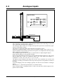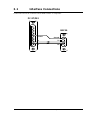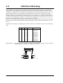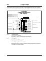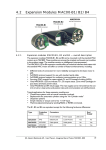
1
SMC20
Step Motor Controller
User Manual
JVL Industri Elektronik A/S
LB0006-03GB
Revised 15.07.97
Copyright 1996, JVL Industri Elektronik A/S. All rights reserved. This user
manual must not be reproduced in any form without prior written permission
of JVL Industri Elektronik A/S.
JVL Industri Elektronik A/S reserves the right to make changes to information contained in this manual without prior notice.
Similarly JVL Industri Elektronik A/S assumes no liability for printing errors or other omissions or discrepancies in this user manual.
MotoWare is a registered trademark
JVL Industri Elektronik A/S
Blokken 42
DK-3460 Birkerød
Denmark
Tlf. +45 45 82 44 40
Fax. +45 45 82 55 50
e-mail: [email protected]
Internet: http://www.jvl.dk
Contents
1
Introduction ................................................................................................................................ 4
1.1
1.2
Features ................................................................................................................................................................ 5
Controller Connections ........................................................................................................................................ 6
2
Hardware .................................................................................................................................... 8
2.1
2.2
2.3
2.4
2.5
2.6
2.7
2.8
Power Supply ....................................................................................................................................................... 9
Motor Connection .............................................................................................................................................. 11
User Outputs ...................................................................................................................................................... 15
User Inputs ......................................................................................................................................................... 16
Analogue Inputs ................................................................................................................................................. 17
Stop Input ........................................................................................................................................................... 18
Status Outputs .................................................................................................................................................... 19
Pin Designations ................................................................................................................................................ 20
3
Interface .................................................................................................................................... 22
3.1
3.2
3.3
3.4
3.5
Interface Connections ........................................................................................................................................ 23
Interface Adressing ............................................................................................................................................ 25
Communication Rate .......................................................................................................................................... 26
Command Syntax ............................................................................................................................................... 27
Checksum Facility .............................................................................................................................................. 28
4
Software .................................................................................................................................... 30
4.1
4.2
4.3
4.4
4.5
4.6
4.7
General Aspects of Controller Software ............................................................................................................ 31
Controller Response ........................................................................................................................................... 33
Command Overview .......................................................................................................................................... 34
System Commands ............................................................................................................................................. 37
Motor Commands .............................................................................................................................................. 40
User Interface Commands .................................................................................................................................. 50
Flow Commands ................................................................................................................................................ 53
5
Appendix ................................................................................................................................... 58
5.1
5.2
5.3
5.4
5.5
Technical Data ................................................................................................................................................... 59
Physical Dimensions .......................................................................................................................................... 60
Memory Utilization ............................................................................................................................................ 61
Accessories ......................................................................................................................................................... 62
Motor Connections ............................................................................................................................................. 63
JVL Industri Elektronik A/S - User Manual - Step Motor Controller
1
Introduction
JVL Industri Elektronik A/S - User Manual - Step Motor Controller SMC20
4
1.1
Features
Stepper Motor Controller Type SMC20 provide a The SMC20 provides the following basic
easy-to-use, cost-effective controller for stepper
feaures:
motors. It combine an advanced motion-control
indexer and motor drive in a single unit.
• 15-45V DC supply (Types SMC23/SMC25)
The Controller can be used as stand-alone unit or
connected to a terminal or personal computer (PC) • RS232C/V24 communication.
via the RS232C/V24 interface. The Controller is
equipped with inputs and outputs which provide the • Simple programming.
user with a high degree of flexibility for tailoring
configuration to the specific application. The Con- • Max. stepping frequency 15kHz.
troller is ideal for controlling small milling machines and drills, handling- and feeder units, etc.,
• Connection of up to 7 controllers on the same
where quick and precise motion control is required
RS232 interface bus.
without the use of components which are large or
costly.
• Baud Rates: 110 - 9600.
The controller is only available in one version compared to JVL’s other controller types.
• Small physical dimensions:
The driver in SMC20 is made as a bipolar chopper
b x h x d: 34 x 100 x 160 mm
driver with a maximum output current of 2.5 Amp.
per motor phase. The motor current can be set by
• Thermal protection.
software commands.
The Controller is equipped with 3 digital User In• 3 User Inputs.
puts and 3 digital User Outputs for general use. 6
analogue inputs can be used for example when a
• 6 Analogue Inputs.
pressure transducer is used to transmit measurement or control values to the Controller.
• 1 Stop Input.
Notice that the inputs and outputs are not overload
protected such as other controllers from JVL. The
• 3 User Outputs.
motor driver is equipped with short-circuit protection which disconnects current to the motor in the
• Connection via DIN41612 socket or
event of a short-circuit. The SMC20 must be poweconnector board type CON10P.
red from a DC supply in the range 15-45V DC.
• Mounting in 19" rack or flush mounting.
5
JVL Industri Elektronik A/S - User Manual - Step Motor Controller SMC20
1.2
Controller Connections
Front end of SMC20 :
"Power" indicator
Indication of
overload
Setup of address,
communicationspeed, etc.
RS232C/V24
Serial communication
TT0202GB
Interface :
The RS 232C Interface enables the Controller to be connected to a computer or terminal.
Up to 7 Controllers can be connected on the same interface bus.
Motor Output :
Enables connection of a 2-phase or 4-phase stepper motor. The output is short-circuit protected. The motor can be controlled with a speed of 15000 Full/Half-steps per second.
Power Supply :
The Controller can be operated from a single supply voltage: from 15 to 45 V DC or 12
to 30 V AC. The selection between DC or AC supply is done by a jumper.
Se xxx
User Inputs :
The Controllers are equipped with 4 noise-suppressed inputs, one of which is reserved
for the Stop function. The remaining 3 User Inputs can be used, for example, for connecting inductive sensors or for synchronization with other controllers. The inputs can operate with TTL signals in the range 0-5V. Notice that the inputs is not equipped with opto
couplers.
JVL Industri Elektronik A/S - User Manual - Step Motor Controller SMC20
6
1.2
Controller Connections
Rear Panel :
Motor Connection
Connector : DIN41612/Ver. B
Supply (15-45VDC/12-30VAC)
Stop Input
3 (9) User Inputs
6 Analogue/Digital Inputs
3 User Outputs
Pulse and direction outputs
TT0203GB
User Outputs :
The Controllers are equipped with 3 User Outputs which for example can be used to drive
small DC motors, or to synchronise the unit with other controllers.
Each output can supply up to 10mA and operates in the range 0 - 5 V DC.
Notice that the User Outputs are not short-circuit protected and optically isolated from
other Controller circuitry.
Analogue Inputs :
The voltages at the Controller's 6 Analogue Inputs can be read using a set of program
commands, thus enabling control of a motor's maximum speed, absolute or relative distance, etc., by the application of a voltage to one of the 6 Analogue Inputs.
The inputs accept voltages in the range 0 - 5.10V, and are protected against short-duration
overloads up to 45V.
Status outputs.
These 4 outputs indicates when the motor moves, when it accelerate/decelerate, direction
of the motor and step-pulses.
7
JVL Industri Elektronik A/S - User Manual - Step Motor Controller SMC20
2
Hardware
JVL Industri Elektronik A/S - User Manual - Step Motor Controller SMC20
8
2.1
Power Supply
Stepper Motor Controller SMC20
Supply
15-45VDC/
12-30VAC
Bidirectional
Input
Output
+5VDC Out
Input 1
Input 2
Input 3/EOT
Stop Input
Power Supply
Input Ground
+5VDC Out
Output 1
Output 2
Output 3
Step
Dir
Ramp
Move
Output Ground
"Power"
Controller
RS232C
Tx-PD
CurrentAdjust.
Analogue Input 1
Analogue Input 2
Analogue Input 3
Analogue Input 4
Analogue Input 5
Analogue Input 6
Analogue Ground
Filter
m.v
TT0204GB
Baud rate select
Protocol Select
Recall program
Checksum Select
Half/Full step
Bipolar
Chopper
Driver
A+
AB+
B-
Motor
"Overload"
To ensure powering of the Controllers is as simple as possible, the Controllers are supplied from a single 15 to 45V DC supply. Alternativly there can be applied 12 to 30 V AC.
See
The Controllers' internal circuitry ensures the correct supply for the interface, control circuitry, etc.
In the event of incorrectly connected polarity of the power supply voltage, the Controllers
are fuse-protected. If an overload occurs, the power should be disconnected and the fuse
replaced. To ensure correct operation of the Controller, it is recommended that a capacitor
(min. 5000µF) is connected across the positive and negative terminals of the external supply.
It is also recommended that the cables used to connect the Controller to the external power supply are minimum 0.75mm².
If the voltage used to supply the Controller falls below a level of 10V, the Controller will
automatically be reset and any program instructions, etc., will be lost. Provision should
there-fore be made to ensure that the supply voltage does not fall below a minimum of
15V, even in the case of mains voltage drop.
The program in the permanent memory (E2PROM) will not be lost.
Notice that SMC20 is not overvoltage protected like other controller types from JVL.
9
JVL Industri Elektronik A/S - User Manual - Step Motor Controller SMC20
2.1
Power Supply
Jumper location :
DC Supply
15-45 V DC
AC Supply
12-30 V AC
TT0205GB
2.1.1
AC Power Supply
The illustration above shows how to set the jumper by DC or AC supply voltage.
Warning ! Do newer move the jumper when power is applied to the controller.
JVL Industri Elektronik A/S - User Manual - Step Motor Controller SMC20
10
2.2
Motor Connection
Connector : DIN41612/Ver. B
Ground
8A
11A
13A
15A
17A
A+
AB+
B-
Screen
TT0206GB
The Controller is intended for use with 2 or 4 phase stepper motors. The Controller provide a motor phase current of up to 2.5A. The phase current is continuously adjustable.
The motor standby current, acceleration/deceleration current and constant speed current
can be set individually. The current is controlled via a set of software commands as described in Section 4.
The Controller Driver consists of a 2-phase bipolar chopper driver. This type of driver
results in optimum utilization of the motor since current is continuously supplied to both
phases of the motor.
The chopper-driver regulates the current at a frequency of 22kHz (nominal) thus ensuring
that the motor control does not produce audible noise.
The switching time of the Driver is very small (<200nS), which can result in high-frequency noise components in the connection between the driver and the motor.
In some cases, this high-frequency noise can result in unwanted interference of other
electronic equipment close to the stepper-motor system. To avoid this problem, screened
cable should be used to connect the Controller to the stepper motor, as illustrated above.
11
JVL Industri Elektronik A/S - User Manual - Step Motor Controller SMC20
2.2
Motor Connection
TT0207GB
2.2.1
Motor Types
Various types of step motor are commonly available:
1. 2-Phase Bipolar (4 terminals)
2. 4-Phase Bi-/Unipolar (8 terminals)
3. 4-Phase Unipolar (6 terminals)-not suitable
Note that type 3 motors (Unipolar) are not suitable for operation with this Controller,
which utilises the Bipolar principle. Note also that a bipolar system typically provides
40% more torque than a unipolar system.
2- or 4-phase motors can be connected as follows:
2.2.2
2-Phase Motors (4 terminals)
This type of motor can be connected directly to the Controller's output terminals.
The current supplied by the Controller may be maximally adjusted to the specified rated
motor phase current.
2.2.3
4-Phase Motors (8 terminals).
This type of motor can be connected in one of two configurations:
1. Serial connection of phases.
2. Parallel connection of phases.
The choice of motor configuration is typically determined by the speed requirements of
the system. For slow speeds (typically less than 1kHz), serial phase connection can be
selected. For speeds greater than 1kHz, parallel phase connection can be selected.
JVL Industri Elektronik A/S - User Manual - Step Motor Controller SMC20
12
2.2
2.2.4
Motor Connection
Serial Connection of Motor Phases:
Serial connection of motor phases provides the same torque as a parallel phase configuration at speeds up to 1kHz but requires only half the motor current. This can influence
the choice of Controller, enabling a Controller with a lower rated motor phase current to
be used (see above illustration).
When the phases of a 4-phase step motor are connected in series, the rated phase current
of the motor should be divided by a factor of 1.41. If for example, the rated current is specified as 4.2A, the Controller must be adjusted to provide a maximum phase current of
3A.
2.2.5
13
Parallel Connection of Phases
Parallel connection of motor phases provides greater output at frequencies above 1kHz
compared with serial connection, but requires twice the phase current. This can influence
the choice of Controller since it is necessary to select a Controller that can provide a greater output than that required with serial configuration (see above illustration). When the
phases of a 4-phase step motor are connected in parallel, the specified rated motor phase
current should be multiplied by a factor of 1.41. If for example, the rated phase current
of a 4-phase motor is 4.2A, the Controller should be adjusted to provide a maximum phase current of 5.9A when the phases are connected in parallel.
JVL Industri Elektronik A/S - User Manual - Step Motor Controller SMC20
2.2
Motor Connection
1 2 3 4 5 6 7 8 9 10
TT0208G B
Half Step
Full Step
Step mode
2.2.6
Step Resolution
The Controller enables either full-step or half-step control of the connected step motor to
be selected. It is often advantageous to select half-step operation since this provides twice
the resolution per motor revolution and can avoid the need for mechanical gearing.
Another advantage of half-step operation is that the resonance frequencies normally encountered with full-step operation are avoided. The resonance frequency of a step motor
varies with load and results in complete loss of power at resonance.
With larger step motors, the resonance frequency will normally be outwith the operating
range of the motor (the frequencies through which the motor is accelerated or decelerated).
The above illustration shows how half- and full-step operation are selected.
2.2.7
Overload Protection
The Controller's driver circuitry is overload protected. The driver output is automatically
disconnected if the peak current exceeds the maximum Controller current by more than
20% for more than 2ms. A short-duration short-circuiting of any two motor terminals will
not damage the Controller and will simply result in an overload indication on the Overload LED on the front panel. To reset the Controller in this case, the Controller supply
voltage should simply be disconnected for a period of 5 seconds (minimum).
Note !
The Controller motor output is not protected against short-circuiting to ground (P-).
JVL Industri Elektronik A/S - User Manual - Step Motor Controller SMC20
14
2.3
User Outputs
Converting the output to 24V voltage level
+24V
4,7kOhm/½W
Output to PLC etc.
4,7kOhm/½W
O1
O-
BC547
Ground (-)
TT0209GB
SMC20's User Outputs enable auxiliary functions such as actuators and small motors to
be controlled by the Controller.
These Outputs enable a step motor to be synchronised with peripheral equipment in the
motion control system.
The outputs are push pull types and can be controlled by software commands. The outputs
provide a maximum rated current of 10mA. The output voltage is nominal 0 or 5 VDC.
The O- terminal is the output ground. Notice that this ground terminal is internally is connected to the other ground terminals in the controller (I-, AG, etc.).
There is 5VDC available at the O+ terminal. This supply voltage can be used for external
purposes. The maximum current drawn from this pin must not exceed 50mA.
Warning !
The Outputs are not protected against inductive transients and short-circuit.
15
JVL Industri Elektronik A/S - User Manual - Step Motor Controller SMC20
2.4
User Inputs
Connector : DIN41612/Ver. B
Conversion from 24V input voltage
24V Input
10kOhm
IIN1
IN2
IN3
24B
25B
26B
27B
I+
29B
IN1
ITT0210GB
Each of the Controller's User Inputs is equipped with a 1st-order low-pass filter which
suppresses frequencies above 6kHz. This filter is used to ensure that electrical noise from
step motors or other equipment in the motion control system does not influence the input
signal.
It should be noted that the status of a User Input is undefined if no connection is made to
the Input.
Some inductive sensors have an open collector output. For sensors with an NPN output,
an external resistor must be connected between the Input to the +supply. For PNP
sensors, an external resistor must be connected between the Input and ground. It is recommended that a resistance of 5kOhm should be used.
Warning !.
It is not allowed to apply a voltage to the inputs higher than 5.0 V. The inputs are not protected against overvoltage.
JVL Industri Elektronik A/S - User Manual - Step Motor Controller SMC20
16
2.5
Analogue Inputs
Connector : DIN41612/Ver. B
Input circuitry:
1kOhm
A1
22nF
6,2V
10kOhm
AG
A6
A4
A2
30B
31B
32B
29A
30A
31A
32A
AG
A5
A3
A1
Analogue Ground
+
0 - 5,1VDC
TT0211GB
The Controller is equipped with 6 Analogue Inputs which can be read using a set of software commands, as described in Chapter 4.
The Analogue Inputs enable, for example, the step motor speed to be controlled by application of an analogue voltage.
The Inputs are protected against short-duration overloads up to 45V.
Each time an Analogue Input is read, a total of 16 samples is made. These values are averaged to minimise the risk that a spurious noise pulse, for example from the step motor
driver, influences a measurement.
The Analogue Inputs can also be used as conventional User Inputs (digital inputs).
Notice that the inputs are not optically isolated.
No special requirements are necessary to use the Analogue Inputs in this way, since at any
time an Input can be used as an analogue input or as a User Input. See Chapter 4 commands: ±A, DA, G±A, JCA, NA, r, s, t, U, VA, W.
The Inputs accept voltages in the range 0V to 5.10V. The Controller uses an 8-bit A/D
converter, providing a resolution of 256 steps. Each step thus corresponds to 20.0mV at
the Input.
To avoid sampling errors, the analogue ground, AG must be used with the 6 Analogue
Inputs.
See Section 5.1, "Electrical Specifications", for further details.
Each Analogue Input is equipped with a 1st-order low-pass filter which suppresses frequencies above 10kHz.
17
JVL Industri Elektronik A/S - User Manual - Step Motor Controller SMC20
2.6
Stop Input
Connector : DIN41612/Ver. B
IStop
ST.
24B
28B
ST is the stop input
I- is the input ground (-)
TT0212GB
To instantaneously stop program execution and thus motor operation, the Controller's
Stop Input is pulled to ground. If the Input is thereafter deactivated, program execution
and thus motor operation will continue and the contents of the position counter will be
retained. It should however be noted that an instantaneous stop in this way will most probably result in the motor being in an undefined position since activation of the Stop Input
does not take account of any pre-set acceleration/deceleration ramps. For further details,
see Section 4. Motor Commands.
JVL Industri Elektronik A/S - User Manual - Step Motor Controller SMC20
18
2.7
Status Outputs
Connector : DIN41612/Ver. B
3B
I-
3A
24B
25A
26A
TT0213GB
SMC20 contains 4 outputs which indicates the following. Notice that all 4 outputs are
TTL compatible (level 0-5V) and they are not protected against shortcircuit.
2.7.1
Move output
This output indicates when the motor is running.
The output will be logic 1 when the motor is running and logic 0 when the motor is in
standby.
2.7.2
Ramp output.
This output indicates when the motor is accelerating or decelerating. The output will be
logic 1 when the motor accelerates or decelerates. The output will be logic 0 when the
motor is running with constant speed or is in standby.
2.7.3
Clk output
Every time the motor moves 1 step there will be a pulse comming at this output.
The pulse with is 16µS.
2.7.4
Dir output
This output indicates which direction the motor is moving.
If the output is logic 1 the motor is moving in positive direction and logic 0 means that
the motor moves in negative direction.
19
JVL Industri Elektronik A/S - User Manual - Step Motor Controller SMC20
2.8
Pin Designations
Connector : DIN41612 Ver. B
Chassis (earth)
Step pulse output
CLK
DIR
P+
Direction output
Power Supply
15-45VDC / 12-30VAC
PA+
AStepmotor
B+
B-
User Outputs
User Inputs
Analogue Inputs
OO1
O2
O3
O+
II1
I2
I3
ST
I+
A6
A4
MOVE
RAMP
AG
A5
A3
Status Outputs
Analogue Inputs
The input ground 24B, output ground 19B and analogue ground 29A are internally connected toghether.
Because of electrical noise it is recommended to use the respective groundterminals toghether with the
corresponding inputs or outputs. The input ground must be used toghether with the inputs etc.
JVL Industri Elektronik A/S - User Manual - Step Motor Controller SMC20
20
21
JVL Industri Elektronik A/S - User Manual - Step Motor Controller SMC20
3
Interface
JVL Industri Elektronik A/S - User Manual - SMC Step Motor Controller SMC20
22
3.1
Interface Connections
The Controller Interface uses the widespread RS232C standard, which provides a great degree of flexibility since all Personal Computers and standard terminals have provision for using this communication
standard.
For operation of the Controller via an RS232C interface, the 3 standard RS232 connections Rx, Tx and
Ground are used.
In general, interface cables should not exceed 10 metres in length but if a longer cable is required, the
interface checksum facility should be used to ensure data integrity. See Section 3.5.
Controller Interface:
5
Signal Ground
3
Tx (Transmit)
Rx (Receive)
2
1
TT0215GB
For communication with the Controller via a PC, the interface connections are illustrated in the fol-lowing figures.
Connection between the Controller and an IBM AT or compatible :
PC-AT
SMC20
5
Ground
Ground
3
Tx
Tx
Rx
Rx
5
3
2
1
2
1
TT0216GB
23
JVL Industri Elektronik A/S - User Manual - Step Motor Controller SMC20
3.1
Interface Connections
Connection between the Controller and an IBM XT/PS2 or compatible :
PC-XT/PS2
SMC20
8
7
6
Ground
5
4
3
2
1
Ground
Rx
Tx
Tx
Rx
5
3
2
1
TT0217GB
JVL Industri Elektronik A/S - User Manual - SMC Step Motor Controller SMC20
24
3.2
Interface Adressing
The Controller can be configured to respond to all communication on the interface ("point-to-point"
communication). In addition, it is possible to connect up to 7 Controllers on the same interface bus, i.e.
"multipoint" communication. For multipoint communication the Controller DIP switches must be set to
assign a unique address to each controller on the interface bus. In this way, each controller only responds to interface commands which are preceded by its preset address. To configure Controllers for
multipoint addressing, the DIP switch marked Tx PD on one (and only one) of the Controllers must be
set to ON. For the remaining Controllers in the multipoint configuration, Tx PD must be set to OFF. For
point-to-point communication, Tx-PD is set to ON on the Controller.
In order to ensure data integrity during communication, it is recommended that the interface checksum
facility is used. Checksum is enabled by setting the CHS DIP-switch to ON. For further details, see Section 3.5.
The DIP switch settings for configuring the interface address on Controllers are given in the following
table:
A0
A1
A2
Address
Protocol
0
0
0
-
Point to point
1
0
0
1
Multipoint
0
1
0
2
Multipoint
1
1
0
3
Multipoint
0
0
1
4
Multipoint
1
0
1
5
Multipoint
0
1
1
6
Multipoint
1
1
1
7
Multipoint
IMPORTANT! : If the address switch settings are changed, the Controller must be reset by switching
off and on the power for the new address to take effect.
1 2 3 4 5 6 7 8 9 10
0
OFF
1
ON
A0 A1 A2
25
Tx-PD
TT0218GB
JVL Industri Elektronik A/S - User Manual - Step Motor Controller SMC20
3.3
Communication Rate
Baud Rates of 110 to 9600 Baud can be selected for communication using the Controller's RS232C interface.
The Baud Rate is configured by setting 3 DIP switches, as shown in the following table.
B0
B1
B2
Baud Rate
0
0
0
110
1
0
0
150
0
1
0
300
1
1
0
600
0
0
1
1200
1
0
1
2400
0
1
1
4800
1
1
1
9600
1 2 3 4 5 6 7 8 9 10
TT0219G B
0
1
B0 B1 B2
IMPORTANT! : If the Baud Rate setting has been changed, the Controller must be reset by switching
the power off and on again for the new Baud Rate to take effect.
Note that the Baud Rate must also be set to the selected value on the PC or terminal used for com-munication with the Controller. In addition, the communication protocol should be set as follows:
(1 start bit) 7 data bits
odd parity
1 stop bit
() A start bit is always used with RS232C/V24 protocol.
JVL Industri Elektronik A/S - User Manual - SMC Step Motor Controller SMC20
26
3.4
Command Syntax
Interface communication with the Controller must ful fill the following command syntax:
Address
Address :
Command
Argument
Checksum Return
It is only necessary to specify the Controller Address if more than 1 Controller is connected to the interface (multipoint configuration). The specified Address is a value in the
range 1 - 7.
Command : The command character(s) to be transmitted to the Controller. See the Software Description in Chapter 4 for details of the Controller commands.
Argument :
The command arguments if any. Certain commands such as the K (Kill) or Z (Smooth
Stop) commands have no argument. (See Software Description).
Checksum : The checksum can be used if long communication lines are used between the Controller
and PC or terminal. The checksum ensures integrity of data transmission on the interface.
If an error occurs, an error message (E1) will be received. It is then necessary to retransmit
the command string (see following page).
Return :
27
ASCII character 13. The return character tells the Controller that the command string is
complete and interpretation of the command can be initiated.
JVL Industri Elektronik A/S - User Manual - Step Motor Controller SMC20
3.5
Checksum Facility
Electrical noise from sources such as electrical motors is a common occurrence in industrial applications. This noise can be completely random in nature and despite effective electrical filtration electrical
noise cannot be eliminated completely. In applications where it is vital to ensure that the system operates precisely as required, it is therefore essential to select a communication rate (Baud Rate) that is not
too high. Moreover, the interface cable used to connect the Controller to a PC or terminal should not
exceed 10m in length. A typical command string used for interface communication with the Con-troller
will be of the following form:
1A3%
In the above example, multipoint communication is used and the command is being transmitted to a
Controller which has address 1. The command is being sent to activate output number 3 (A3). The
communication checksum for transmission of a command is determined as follows. First, the ASCII value of each character in the command string is determined. The ASCII values are then summed and the
result divided by 128. The integer-result of the division is discarded, while the remainder is used as the
checksum. Calculation of the checksum for the above example is thus as follows:
Address character
1 = ASCII49
Command character A = ASCII65
Argument character 3 = ASCII51
Sum + remainder = (49+65+51)/128
Checksum = Remainder * 128
If an error occurs during transmission of the command string, the checksum will be incorrect and the
Controller will return the error message "E1" indicating that the Controller could not interpret the received command string. The command must then be re-transmitted. If the Controller continues to transmit
"E1", the interface Baud Rate should be reduced or a shorter cable used to connect the computer to the
Controller.
The Checksum facility is activated by setting the CHS DIP-switch to ON.
IMPORTANT! : If the checksum switch setting is changed, the Controller must be reset by switching
the power off and then on for the new setting to take effect.
1 2 3 4 5 6 7 8 9 10
TT0219G B
0
1
B0 B1 B2
JVL Industri Elektronik A/S - User Manual - SMC Step Motor Controller SMC20
28
29
JVL Industri Elektronik A/S - User Manual - Step Motor Controller SMC20
4
Software
JVL Industri Elektronik A/S - User Manual - Step Motor Controller SMC20
30
4.1
General Aspects of Controller Software
Before the individual software commands are described in detail, it is necessary to describe some general aspects of the Controller software structure.
The Controller is equipped with 2 types of storage memory, both of which are accessible
to the user. These are used for storing programs and operational parameters sent from a
computer or terminal.
The first of these storage memories is referred as the "working memory" in the following
pages. The Controller's working memory is used during connection to a computer or terminal. The working memory is a volatile memory; its contents are deleted when the Controller is switched off. The working memory can also be used for storing instructions
during programming.
The second of the Controller's storage memories is an E²PROM, i.e. a non-volatile memory which retains its contents when the Controller is switched off. This is referred to as
the Controller's "permanent memory" in the following description. The Controller's permanent memory is intended for use when the Controller is used as a Stand alone unit, i.e.
is not connected to a computer or terminal.
Use of the permanent memory enables the Controller to begin execution of pre-programmed instructions without requiring connection to an external PC or terminal.
Permanent memory can also be used if the Controller is connected to a PC or terminal. In
this case it is typically used to store frequently used program sequences which can be preprogrammed and downloaded to the permanent memory.
4.1.1
Position Counter.
The Position Counter is a storage register which keeps track of the motor's current position during operation. The Position Counter can be reset by the I (Initialise) or H
(Home)command (see Sections 4.3 and 4.4). The Position Counter's contents can also be
read or changed using the commands V1 and f[±n].
When the Position Counter reaches its maximum value of +8,388,607 or -8,388,608, the
motor stops automatically.
4.1.2
Command Descriptions.
The following pages (Sections 4.3 to 4.6) describe each of the commands used for programming the Controller.
To avoid any misunderstanding regarding the use of the commands and command syntax,
the following text convention should be noted:
Each command is described by one or more command characters followed by a word in
parentheses. The actual command used to program the Controller using the command
syntax consists of the characters, not the word which is included in the description as a
mnemonic. Note that many of the command descriptions include examples of the
command string.
Almost all commands are followed by one or more parameters: either a value, or a plus
(+) or minus (-) sign. It is important that the speci-fied numeric value is within the permitted ran-ge since the Controller will not interpret parameters outwith the allowable range. See also Section Command Syntax, page 27 for details of the Controller command
syntax.
31
JVL Industri Elektronik A/S - User Manual - Step Motor Controller SMC20
4.1
General Aspects of Controller Software
4.1.3
Operating Modes.
The Controller can be operated in 1 of 3 modes:
1) Standby Mode.
Standby Mode occurs after a K (Kill), Z (Smooth Stop) or PX (Program Exit)
command, and after execution of a program.
2) Programming Mode.
This mode is used when a program is read in to the Controller or to edit an existing
program. Use the PO (Program) or PE (Program Enter) command to set the
Controller to Programming Mode.
3) Execute Mode.
The E (Execute) command is used to execute the program currently in the Controller's
working memory.
Program execution stops when all commands have been executed or if interrupted by
a K or Z command. Thereafter, the Controller returns to Standby Mode.
4.1.4
Programming.
When creating a new program, the first command is always PO, i.e. the Controller is set
to Programming Mode. The actual program commands can then be keyed-in.
Once all the required commands have been programmed, the E command is used to
switch the Controller to Execute Mode and the program is executed. To store the program
in permanent memory, the M (Memory save) command can be used once program executi-on is complete. Programming Mode can also be interrupted using the PX (Program
Exit) command, in which case the Controller will be set to Standby Mode.
A typical sequence for programming the Controller is as follows:
1) Controller switched on.
Mode:
Standby
2) PO (Program) command
keyed-in.
Program
3) Required sequence of
program commands keyed-in.
Program
4) PX (Program Exit) command
keyed-in, after which the
Controller is set to Standby Mode.
Standby
5) E (Execute) command
keyed-in
Execute
*
The entire program is then executed, unless an interrupt occurs via K (Kill) or Z
(Smooth Stop) command.
6) The program can be stored in
permanent memory by keying-in
the M - (Memory Save) command.
Standby
It should be noted that at power-up, the error message E1 will probably be received when
communication is first established between the Controller and a PC/terminal. This is due
to transients which arise on the interface cable when the computer or Controller is switched on.
JVL Industri Elektronik A/S - User Manual - Step Motor Controller SMC20
32
4.2
Controller Response
Each time the Controller receives a command or query via the interface, it responds to the PC or terminal with a short response string. The syntax of the response string is as follows:
Reply Code Argument Checksum Carriage
Return
Reply Code -The Reply Code is the actual response to the received command and is one of the
following:
Y= (Yes) The command has been received and will be, or has been, complied with.
B= (Busy) The Controller is busy with program execution and is not ready to receive
the command or query.
R= (Ready) The Controller is ready to execute a command or respond to a query.
V= (Verify) Position or User Input/Output status. This message will only occur if the
Controller is queried about the status. See the descriptions of the V1 and V2
commands in Sections 4.3 and 4.5 for further details.
E = (Error) An error has been found in the received command and the Controller is not
able to comply with the command. This response returns an argument which indicates the type of error as follows:
E1
E2
E3
E4
E5
E6
Parity Error after receiving one or more characters. Checksum Error. The received command string was too long.
The command argument is too long or is unnecessary.
The working memory is full.
Unknown command or the Controller is unable to comply with the received
command.
The Position Counter has exceeded its maximum of -8,388,607 or +8,388,607
steps, the motor has been stopped. Error in Parameters ( R, S, T ).
An error occurred during transmission to or from the Controller's Permanent
Memory.
Argument - An argument to the response will only occur with E (Error) or V (Verify) messages.
The argument consists of 1 to 7 characters.
Checksum - A checksum value is only included in the response string if the checksum facility is
enabled via the DIP switch setting on the Controller (set to ON).
See the description of the checksum facility in Section Checksum Facility, page 28 for
further details.
CR -
33
Terminates the response string. ASCII value 13.
JVL Industri Elektronik A/S - User Manual - Step Motor Controller SMC20
4.3
Command Overview
System Commands :
E
f [±nnnnnnn]
F
I [n]
K
M
PE
PO
PX
Q
TP
V1
X
Z
(Execute)
Starts program execution.
(Forcing Pos.) Reads in new position.
(Feedback)
Status query to the Controller.
(Initialize)
Resets Controller Registers (software reset).
(Kill)
Stops execution of current program.
(Memory)
Saves working program in Permanent Memory.
(Program Enter) Sets the Controller to Programming Mode without erasing
existing program in working memory.
(Program)
Sets the Controller to Programming Mode. This command erases
any program instructions already in working memory.
(Program Exit) Exits Programming Mode. Returns to Standby Mode.
(Query)
Displays the program currently stored in Working Memory.
(Temperature) Returns the current temperature of the Controller.
(Verify)
Returns the Position Counter value.
(Recall)
Loads program from Permanent Memory into Working Memory.
(Smooth Stop) Stops program execution slowly taking account of deceleration
ramp.
Motor Commands :
[±nnnnnnn]
Relative positioning given by direction of rotation (+/ ) and number of steps.
±A [n].[n1-n2]
Relative positioning controlled by voltage at Analogue Input.
CR [nnnn]
(Current Ramp) Determines motor current during acceleration.
CS [nnnn]
(Current Start) Determines motor current when stationary.
CT [nnnn]
(Current Top) Determines motor current at top speed.
g [±]
(Velocity)
Continuous operation forward/reverse.
G [±nnnnnnn] (Goto)
Absolute positioning.
G±A [n].[n1-n2](Goto)
Absolute positioning controlled by voltage at Analogue Input.
H [±]
(Home)
Resets motor and electronic circuitry.
N [n1n2.n3n4] (Input Setup) Starts/stops motor in accordance with User Inputs.
NA [p1.p2]
(Input Setup) Starts/stops motor in accordance with Analogue Inputs.
R [nnnnn]
(Ramp)
Acceleration/deceleration parameter (1-10000 steps).
RT [nnnn]
(Ramp Time) Acceleration/deceleration parameter (0.01-10 seconds).
RS [nnnnn]
(Ramp Slope) Acceleration/deceleration parameter (10-30000 step/s²).
S [nnnn]
(Start Rate)
Minimum speed.
T [nnnnn]
(Top Rate)
Maximum speed.
r [n1.n2]
(A/D Ramp)
Same as R, controlled by voltage at Analogue Input.
s [n1.n2]
(A/D Start Rate) Same as S, controlled by voltage at Analogue Input.
t [n1.n2]
(A/D Top Rate) Same as T, controlled by voltage at Analogue Input.
VR
(Verify Ramp) Returns the current acceleration/deceleration parameter.
VS
(Verify S. Rate) Returns the current Start Rate parameter.
VT
(Verify T. Rate) Returns the current Top Rate parameter.
JVL Industri Elektronik A/S - User Manual - Step Motor Controller SMC20
34
4.3
Command Overview
(continued)
User Interface :
A [n]
C [n]
U [n]
VA [n]
VA
V2
W [n]
(Activate)
(Clear)
(Until)
(Verify Ainput)
(Verify)
(Wait for)
Activates one of the outputs.
De-activates one of the outputs.
Repeats program(segment) until a specified input is activated.
Returns (measures) voltage at one of the 6 Analogue Inputs.
Returns (measures) the logic levels of the Analogue Inputs.
Returns status of user inputs and outputs.
Pauses program execution until a specified input is activated.
D [nnn]
DA [n].[n1-n2]
J [n1]
JC [n].[n1]
JCA [p].[n1]
(Delay)
(Analog Delay)
(Jump)
(Jump Cond.)
(Jump Cond.)
JS [n1]
RET
L [nnn]
(Jump Sub)
(Return)
(Loop)
Wait a specified time.
Wait a specified time controlled by analogue voltage.
Unconditional jump to a specified program line.
Conditional jump to a specified program line.
Conditional jump to a specified program line when specified
voltage is applied to Analogue Input.
Unconditional jump to sub-routine.
Return from sub-routine.
Repeat program segment a specified number of times.
Flow Commands :
35
JVL Industri Elektronik A/S - User Manual - Step Motor Controller SMC20
4.3
Command Overview
STANDBY MODE
PO
PROGRAM MODE
Erase "old" Program
M
Save Program
PE
PX
PO
Erase Program
Q
Q
Show Program
Show Program
+/- [nnnnnnn] (Relative pos.)
M
A [n] (Activate Output)
Save Program
A+/-[n].[n1-n2] (Relative A/D pos.)
F
C [n] (Clear Output)
Show Status
D/DA [n] (Delay)
I [n]
f [+/-nnnnnnn] (Force Position)
Initialise pos./outputs
g+/- (Velocity)
VR
G [+/-nnnnnnn] (Goto)
Verify ramp
G+/-A[n].[n1-n2] (Goto A/D pos.)
VS
VT
H+/- (Home)
Verify Start Rate
I [n] (Initialize)
J [nnn] (Jump)
Verify Top Rate
JC [n].[nnn] (Jump Conditionally)
VA
JS/RET (Jump Subroutine)
Measure Analogue Voltage
L [nnn] (Loop)
V1
N /NA[p1].[p2] (Input Setup)
Verify Position Counter
R, RS, RT, S, T (Motor Parameters)
V2
r, s, t (Motor Parameters A/D)
Show I/O status
U [n] (Untill)
A [n]
C [n]
f +/-[n]
H+/-
R, S, T
+/- [n]
W [n] (Wait)
Activate Output
Insert command on
new line in Program
Deactivate Output
Preset Position
TP
Show Temperature
VR/VS/VT
Find Mechanical 0-Point
VS
Adjust Motor Parameters
Show Start Rate
VT
Show Top Rate
VA [n]
Relative Positioning
Show Status at A. Inputs
V1
E
Show Position Counter
V2
E
Show Ramp
Show I/O Status
E
EXECUTE MODE
Stop Program Execution
F
K
Z
Program Execution Completed
Show Status
Execution of Program
TT0221GB
JVL Industri Elektronik A/S - User Manual - Step Motor Controller SMC20
36
4.4
System Commands
4.4.1
E (Execute)
Starts program execution. The Execute command can also be used to complete a programming sequence. The command can be used when the Controller is either in Standby
Mode or Programming Mode.
4.4.2
f+/-[nnnnnnn] (Forcing position)
Assigns a specified value to the Position Counter.
The position can be specified in the range -8,388,607 to +8,388,607, both values included. The command can be used when the Controller is in Standby Mode and in Programming Mode.
Example:
f+100 assigns a value of +100 to the Position Counter.
4.4.3
F (Feedback)
Status Query to the Controller. 1 of 3 responses will occur.
1) If the Controller is ready to receive and execute commands, the Status Query
response is R (Ready).
2) If the Controller is busy, the Status Query response is B (Busy).
3) If the motor has been stopped automatically because of an overflow in the
Position Counter, the Status Query response is E5 (Error 5).
4.4.4
I [1-3] (Initialize)
The Initialize command is used to reset either the Position Counter and/or User
Outputs.
I1 Resets the Position Counter only.
I2 Resets the User Outputs only.
I3 Resets both the Position Counter and User Outputs.
4.4.5
37
K (Kill)
The Kill command has the highest priority since it stops program execution regardless of
motor movement. The Kill command is effective immediately, i.e. as soon as the
command is issued, the Controller is set to Standby Mode. To begin program execution
once more, a new Execute command must be used. The pro-gram will start from the beginning. It is often necessary to use the H (Home) com-mand before starting a new execution of a program since the motor position will be arbitrary owing to the instantaneous
stop resulting from the Kill command.
JVL Industri Elektronik A/S - User Manual - Step Motor Controller SMC20
4.4
4.4.6
System Commands
M (Memory Save)
To enable completed programs to be permanently stored after the power has been switched off, the Controller is equipped with a permanent, non-volatile memory. The Memory
Save command is used to store the contents of the Controller's volatile working memory
in the non-volatile permanent memory. Only 1 pro-gram can be stored in permanent memory at a time. If the REC DIP switch is set to "ON", the program stored in permanent
memory is automatically recalled and exe-cuted when the Controller is switched on.
1 2 3 4 5 6 7 8 9 10
TT0222GB
OFF
ON
REC
4.4.7
PE (Program Enter)
The Program Enter command is used to set the Controller to Programming Mode without
erasing any existing instructions in the working memory. This com-mand is primarily
used when editing a program during development.
4.4.8
PO (Program)
The Program command sets the Controller to Programming Mode, i.e. so that the Controller is ready to receive programming instructions. Each time the Program command is
used, the contents of the Controller's working memory are reset, erasing any existing instructions. (See also the Program Enter command above and the description of the Program command at the beginning of this Chapter.)
4.4.9
PX (Program Exit)
The Program Exit Command is used to exit Programming Mode and set the Controller to
Standby Mode. A program can then be executed or a new program keyed-in.
4.4.10
Q (Query)
The Query command returns the program currently stored in working memory, including
run-time parameters. If a printout of the program in permanent memory is required, the
X (Recall Program) command should be used prior to the Query command. Note that use
of the Recall Program command will erase the contents of the Controller's working memory.
JVL Industri Elektronik A/S - User Manual - Step Motor Controller SMC20
38
4.4
System Commands
4.4.11
TP (Temperature)
Returns the current temperature of the Controller.
The Temperature command can be used to verify that the Controller is operating within
its specified temperature range of 0-50°C. If, under "worst-case" conditions, a temperature greater than approximately 60°C is registered, ventilation of the Controller must be
improved.
4.4.12
V1 (Verify Pos.)
The Verify Position command is used to read the contents of the Position Counter.
The value returned is relative to 0, the Home position. (See also the Home command).
4.4.13
X (Recall Prog.)
The Recall Program command is used to read the program (if any) stored in the
Controller's non-volatile, permanent memory and load the program into the working memory. This command can be used advantageously if, for example, a program is to executed at regular intervals. A Recall Program command is then followed by an Execute
command, thus starting program execution immediately.Note that each time the Recall
Program is used to load a program from permanent memory in to working memory, any
instructions in the Controller's working memory will be erased.
4.4.14
Z (Smooth Stop)
The Smooth Stop command has the same function as the Kill command.
except that the motor is decelerated in accordance with the specified R, S, T parameters. The Smooth Stop command is thus used to ensure that the motor does not stop at an
undefined position. (See also the K (Kill) command).
39
JVL Industri Elektronik A/S - User Manual - Step Motor Controller SMC20
4.5
4.5.1
Motor Commands
+/ [nnnnnnn] (Relative)
The Relative command is similar to the Goto command. Instead of positioning the motor
relative to the 0 (Home) position, the Relative command positions the motor relative to
its current position. The command specifies the direction (+ or -) and the number of steps
the motor is moved. The number of steps can be specified in the range 1 to 8,388,607
steps.
Example :
+15 , A Relative positioning command of +15 will advance the motor 15 steps relative to its current position.
4.5.2
±A [n].[n1-n2]
This command is used to move the motor a specified number of steps, using the value of
an analogue voltage.
The command parameter "n" specifies which Analogue Input (1-6) is used for con-trolling the movement. The parameters "n1" and "n2" specify the step interval, whe-re n1 indicates the number of steps corresponding to an input voltage of 0V, and n2 indicates the
number of steps corresponding to an input voltage of 5.1V. n1 and n2 can be specified
from 1 to 65000 steps.
Example :
+A1.100-1000
The above command advances the motor (indicated by +) 100 steps if a voltage of 0V
is applied to Analogue Input 1, and 1000 steps if a voltage of 5.1V is ap-plied. For
voltages between 0V and 5.10V a linear interpolation is used to de-termine the number of steps the motor is moved (see figure below).
Steps
1000
100
Voltage (V)
0
5,10
TT0223GB
JVL Industri Elektronik A/S - User Manual - Step Motor Controller SMC20
40
4.5
Motor Commands
The current supplied to a stepper motor can be adjusted to specified values for standby, acceleration/
deceleration, and top speed. Normally only a small current is required when the motor is stationary since
the static inertia of a typical stepper motor is much less than the inertia while the motor is rota-ting, depending on the speed range of the motor.
The torque of a stepper motor is directly proportional to the applied current, up to the specified phase
current (see the specifications for a given motor).
In the nominal current is exceeded, the motor will overheat and only very little increase in torque will
result.
The following 3 commands are used to specify the current supplied to the motor. The commands can be
used at any point in a program. All 3 commands can be specified and changed continuously throughout
a program.
If any of the commands is omitted, the respective parameter assumes a default value of 1000mA.
4.5.3
CS [0-6000] (Current Standby)
Determines motor current when the motor is stationary.
4.5.4
CR [0-6000](Current Ramp)
Determines motor current during acceleration/deceleration.
4.5.5
CT [0-6000](Current Top)
Determines motor current at maximum speed.
Example:
(Program)
.
CS500 Sets motor Standby Current to 500mA (0.5A).
CR2000 Sets motor Ramp Current during acceleration/deceleration to 2000mA (2A).
CT1500 Sets motor Top Current to 1500mA (1.5A) at top speed.
+100
Advances the motor 100 steps.
CT2100 Sets new motor Top Current to 2100mA (2.1A).
.
.
41
JVL Industri Elektronik A/S - User Manual - Step Motor Controller SMC20
4.5
Motor Commands
4.5.6
g+/- Velocity Mode
The Velocity Mode command is used to move the motor continuously in a
specified direction.
The command is followed by a + or - parameter which specifies the direction of movement. To stop the motor once the Velocity Mode command has been used, a Z (Smooth
Stop) or K (Kill) command must be used.
If the N (Input Setup) command is used before the g± command, the conditions specified
by the N command can also stop the motor. (See the description of the Input Setup (N)
command for further details.)
It should be noted that the Position Counter is updated while the Velocity Mode
command is executed. The command can only be used when it is included in a program.
4.5.7
G+/- Goto
The Goto command is used for absolute positioning of a stepper motor.
The specified parameter value refers to the Position Counter and can be specified in the
range -8,388,607 and +8,388,607.
4.5.8
G±A [n].[n1-n2] (Analog Goto)
The Analog Goto command is used for absolute positioning of a motor
motor (similar to the G±[n] (Goto) command) but the required position is determi-ned by
the analogue voltage applied to a specified Analogue Input. The "n" com-mand parameter
specifies which Analogue Input (1-6) is used for the control sig-nal. Parameters "n1" and
"n2" specify the required positions corresponding to ap-plied voltages of 0V and 5.10V
respectively. The specified position can be set in the range +0 to +65000.
See also the ±A command
Example:
G±A2.0-800
The above example moves the motor to position +0, if a voltage of 0V is applied to
Analogue Input 2, and to position +800 if the applied voltage is 5.10V.
For applied voltages between 0 and 5.10V a linear interpolation between positions
+0 and +800 is made.
4.5.9
H+/- Home
The Home command enables an electrical and mechanical reset of the system to a predefined reference position. As soon as the Controller receives the Home command, the
motor will move in the specified direction (either H+ or H ).
As soon as the EOT (End of Travel) input becomes low, the motor will stop. The motor
is then at its reference position. The speed at which a reset occurs is deter-mined by the
S ( Start Rate ) command.
After execution of a Home command, the Position Counter is reset to "+0".
The home input (EOT) is shared with input3 pin 27B.
JVL Industri Elektronik A/S - User Manual - Step Motor Controller SMC20
42
4.5
4.5.10
Motor Commands
N [n1n2.n3n4] Input setup
The Input Setup command enables a motor to be started or stopped using control signals
at the User Inputs.
The Input Setup command itself does not start or stop the motor. It only determines how
the next motor command ±[n] / g[±] / G±[n] will be interpreted and executed. Thereafter
the Input Setup command is inactive until a new Input Setup command is executed. To
subsequently start or stop the motor using the control signal at a User Input, a new Input
Setup command must precede the new motor command.
Command Syntax:
Stop Input
Start Level
Start Input
Stop Level
N
n1 n2
. n3 n4
User Input 1 = 1 1
0 0
Input activated by "0"
User Input 2 = 2 2
1 1
Input activated by "1"
User Input 3 = 3 3
2 2
TT0224GB
9 9
Function inactive
n1: Specifies the User Input (1-3) used to start the motor.
n2: Specifies the User Input (1-3) used to stop the motor.
n3: Refers to n1 in that n3 determines the logic level to be applied to the specified
User Input in order to start the motor. If n3 is set to 0, the motor will start when
logic level 0 is applied to the specified User Input.
If n3 is set to a value between 2 and 9, the start function will be inactive and the motor will start immediately.
n4: Refers to n2, in that n4 determines the logic level to be applied to the speci-fied User
Input in order to stop the motor. If n4 is set to 1, the motor will stop when logic level
1 is applied to the specified User Input.
If n4 is set to 0, the motor will stop when the level changes from logic 1 to logic 0.
If n4 is set to a value from 2 to 9, the stop function will be inactive and the motor
will only be stopped a motor command requires it.
(continued on following page)
43
JVL Industri Elektronik A/S - User Manual - Step Motor Controller SMC20
4.5
Motor Commands
(continued)
When the Input Setup command is used for a movement sequence, the Position
Counter is updated normally.
While the motor is moving, a Z (Smooth Stop) or K (Kill) command can be used to stop
the motor. Program execution can also be halted using a K (Kill) or Z (Smooth Stop)
command while the Controller is waiting for a start signal from a User Input.
Example 1:
The command N13.01 followed for example by a g+ command will start the motor when
User Input 1 attains a voltage of logic 0. Note that it is a logic level 0, and not a change
from "1" to "0" that activates a start.
The motor will move according to the specified parameters and run at normal speed until
a voltage corresponding to logic "1" is applied to User Input 3. Thereaf-ter the motor will
decelerate until it stops, and the next program command is executed.
Example 2:
The command N21.10 followed for example by a +10000 command will start the motor
when User Input 2 is logic "1" and operate at normal speed for 10000 steps (including
deceleration ramp), or until a change from logic 1 to logic 0 occurs at User Input 1.
The motor will then decelerate and the next program command is executed.
Example 3:
The command N11.19 followed for example by a G+3500 command will start the motor
when User Input 1 becomes logic "1" and stop when position +3500 is rea-ched. The motor will operate in accordance with the parameters specified by the R, S and T commands.
JVL Industri Elektronik A/S - User Manual - Step Motor Controller SMC20
44
4.5
4.5.11
Motor Commands
NA [p1.p2] Analog Input setup
This command enables start/stop control of the motor via control signals at the analogue
inputs. The principle of the Analog Input Setup command is the same as the Input Setup
command, N [n1n2.n3n4].
The 2 command parameters (p1 and p2) specify start and stop conditions re-spectively.
The Analog Input Setup command itself does not start or stop the motor. It only influences how the next motor command ±[n] / g[±] / G±[n] will be interpreted and executed.
Thereafter the command is inactive. To subsequently start the motor again using control
signals at an Analogue Input, a new Analog Input Setup command must precede the new
motor command.
The complete syntax for the Analog Input Setup command is as follows:
Start Level
Stop Input
(0-255)
(Analog Input 1-6)
<>
<>
Start Input
Stop Level
(Analog Input 1-6)
(0-255)
NA a1 m n1 . a2 m n2
p1
p2
TT 0225GB
p1: If the start conditions are fulfilled, the motor is started. If p1 is assigned the character
X, an unconditional start is defined, and the motor will start immediately the motor
command is executed.
p2: If the stop conditions are fulfilled, the motor will be stopped. If p2 is as-signed the
character X, an unconditional stop is defined and the motor will operate until the
specified motor command (±[n], g±, G±[n]) requires it to stop.
a1: Specifies the Input used for the start control signal. a1 can be specified in the range
A1 to A6, corresponding to Analogue Inputs 1-6.
a2: Specifies the Input used for the stop control signal. a2 can be specified in the range
A1 to A6, corresponding to Analogue Inputs 1-6.
n1: Specifies the Start Reference Value. The Reference Value is compared with the measured voltage at the specified start Input (a1). The Start Reference Value can be set
in the range 0 to 255.
n2: Specifies the Stop Reference Value. The Reference Value is compared with the measured voltage at the specified stop Input (a2). The Stop Reference Value can be set
in the range 0 to 255.
m: The operator for comparison between the Reference Value and the mea-sured value
at the input(s). To start/stop the motor when the voltage at the respective analogue
input is less than the Reference Value, the ope-rator should be specified as "<". To
start/stop the motor when the applied voltage is greater than the Reference Value,
the ">" operator is specified.
45
JVL Industri Elektronik A/S - User Manual - Step Motor Controller SMC20
4.5
Motor Commands
(continued)
Since n1 and n2 are specified as values in the range 0-255 and the voltage measured at
the Analogue Inputs is in the range 0-5.10V, a conversion must be made when specifying
n1 and n2, either by converting the Reference va-lues to a voltage or vice versa. The conversion is made as follows:
Vref = 0.02 x norn = 50 x Vref
Example:
If a Reference Value of 1.20V is required, n should be specified as:
n = 50 x 1.2 = 60
Program Example 1:
.
.
NAA1<60.A6>100
+10000
.
In the above program example, the motor is started if the applied voltage at Analogue Input 1 is less than 1.2 Volts (see conversion example above). Otherwise nothing occurs.
When the motor is running, it is stopped either after completion of the 10000 steps or
when the voltage at Analogue Input 6 is greater than or equal to 2V (n2=100).
Program Example 2:
.
.
NAX.A5>220
G+100000
.
The parameter specification X indicates that the start condition is inactive and the motor
will therefore start immediately. Thereafter the motor will stop when position +100000
is reached or if the applied voltage at Analogue Input 5 is greater than or equal to 4.4V
(n2=220).
The K (Kill) and Z (Smooth Stop) commands can be used to interrupt program execution.
JVL Industri Elektronik A/S - User Manual - Step Motor Controller SMC20
46
4.5
Motor Commands
In contrast to a normal DC motor (which is "Self-commutating"), a stepper motor is electrically commutated. That is, a stepper motor is driven by magnetic fields which are controlled electronically. When
the motor is loaded, the magnetic fields will eventually not be powerful enough to continue to turn the
rotor. The motor will stop, but the electronics will continue to move the magnetic fields at the same
speed. It is therefore important that a motor is accelerated and decelerated at appropriate rates, in or-der
for the magnetic fields to drive the rotor.
Similarly a stepper motor has a maximum speed and if this is exceeded the motor can no longer provide
the same power and will simply stop.
There are 3 basic parameters which should be considered:
4.5.12
S [16-2000] Start Rate steps/second
The Start Rate is the speed at which the motor is started. If it is set too high, the motor
will simply stop at an arbitrary position. The Start Rate can be set in the range 16 to 2000
steps/second. The default Start Rate is 100 steps/second.
4.5.13
T [16-15000] (Top Rate steps/second)
The Top Rate specifies the maximum speed of the motor. If it is set too high, the motor
will be unable to provide enough power and will stop at an arbitrary position. The Top
Rate can be set in the range 16 to 15000 steps/second. The default Top Rate is 1000 steps/
second.
4.5.14
4.5.15
4.5.16
R [1-10000] (Ramp)
RT [1-1000] (Ramp time)
RS [10-30000] (Ramp slope)
This value specifies how the motor is accelerated and decelerated. The value can be specified in 1 of 3 forms. R (Ramp) is used if the required acceleration/deceleration is specified in steps. RT (Ramp Time) is used if the required acceleration/deceleration is
specified in terms of time, and RS (Ramp Slope) is used if the required acceleration/deceleration is specified in steps/second². Ramp Slope can be used advantageously if the
Top Rate or Start Rate are repeatedly changed in a pro-gram, since the acceleration per
unit of time remains the same. If too high an acceleration/deceleration rate is selected, the
motor will stop.
R [n] can be specified in the range 1 to 10000 steps. The default Ramp is 100 steps.
RT [n] can be specified in the range 1 to 1000, corresponding to a range from 0.01 to 10
seconds.
RS [n] can be specified in the range 10 to 30000 steps/second².
Examples:
R100 specifies an acceleration/deceleration of 100 steps. RT50 results in an acceleration/
deceleration time of 0.5 seconds. RS900 gives an acceleration/deceleration rate of 900
steps/second². All 3 parameters must be specified in a program and can be adjusted at any
point in the program. If T (Top Rate) is set to a value less than S (Start Rate), the motor
will operate at the Top Rate specified by T without accelerating or decelerating.
Speed
Top Rate
Start Rate
Time
Ramp
47
TT0226GB
JVL Industri Elektronik A/S - User Manual - Step Motor Controller SMC20
4.5
4.5.17
4.5.18
4.5.19
Motor Commands
r [n1.n2] (A/D Ramp Step)
s [n1.n2] (A/D Start Rate)
t [n1.n2] (A/D Top Rate)
These 3 commands are used to determine the motor parameters R, S
and T using the analogue voltage applied at one of the 6 Analogue Inputs.
The r [n1.n2] command determines the Ramp Step parameter.
The s [n1.n2] command determines the Start Rate parameter
The t [n1.n2] command determines the Top Rate parameter.
n1 specifies the Analogue Input used for controlling a given step/frequency. n1 can be
specified in the range 1-6 corresponding to the required Analogue Input 1 to 6. The voltage applied to the specified input must be in the range 0 to 5.10V.
n1
Analog Input
1
2
3
4
5
6
AN1
AN2
AN3
AN4
AN5
AN6
TT0227GB
n2 specifies the value corresponding to full-scale input voltage (5.10V) either in terms of
steps for the r [n1.n2] command, or in terms of frequency for the s [n1.n2] or t [n1.n2]
command.
n2 can be specified as a value in the range 1 to 10 according to the following table for
Ramp, Start Rate and Top Rate.
n2
1
2
3
4
5
6
7
8
9
10
r[n1,n2]
s[n1,n2]
t[n1,n2]
step
step/sec
step/sec
100
200
300
400
500
600
700
800
900
1000
100
200
300
400
500
600
700
800
900
1000
1000
2000
3000
4000
5000
6000
7000
8000
9000
10000
TT0228GB
A voltage of 0V at a specified Analogue Input always corresponds to either 16 steps for
the r [n1.n2] command, or 16 steps/second for the s [n1.n2] or t [n1.n2] commands.
The VR, VS and VT commands can be used to verify current parameter settings. See the
description of these commands for further details.
(continued on following page)
JVL Industri Elektronik A/S - User Manual - Step Motor Controller SMC20
48
4.5
Motor Commands
(continued)
Example:
The command t1.4 is used in a program. When the program is executed, the
Controller measures a voltage of 2.5V at Analog Input 1 (AN1). This voltage is converted
to a frequency of:
2.5 x 4000
= 1953 Hz = 1953 step/sec
5.10
This frequency is then used for the next motor movement. The specified value of n2 in
the example results in 0V corresponding to a frequency of 16Hz and full-scale 5.10V corresponding to 4000Hz.
4.5.20
4.5.21
4.5.22
VR (Verify Ramp)
VS (Verify Start Rate)
VT (Verify Top Rate)
The Verify Ramp, Verify Start Rate, and Verify Top Rate commands can be used to verify the current values of the motor parameters R, S and T.
VR returns the value of the Ramp Step "R" in steps. VS returns the value of the Start
Rate "S" in steps/second. VT returns the value of the Top Rate in steps/second.
Example:
A verification of the current Top Rate is required. The following command string is therefore sent to the Controller:
VT (carriage return)
The Controller responds:
T1000 (carriage return)
Indicating the current Top Rate is 1000 steps/second.
VR, VS and VT can also be used to check the value of the motor parameters determined
by the r [n1.n2] , s [n1.n2] and t [n1.n2] commands.
49
JVL Industri Elektronik A/S - User Manual - Step Motor Controller SMC20
4.6
4.6.1
User Interface Commands
A [1-3] (Activate Output)
The Activate Output command sets a specified User Output to logic "1".
The command character is followed by a parameter value of 1 to 3 which specifies which
output is to be activated.
Example: A2 sets Output 2 to logic "1".
4.6.2
C [1-3] (Clear Output)
The Clear Output command sets a specified User Output to logic "0".
The command character is followed by a parameter value of 1 to 3 which specifies, which
output is de-activated.
Example: C1 sets Output 1 to logic "0".
4.6.3
4.6.4
U [1-3] (Until)
U [A1-A6] (Until analogue)
The Until command is used to repeat a program segment until logic "0" is applied to a
specified input (see Electrical Specifications).
Either the entire program or only a specified segment can be repeated. The User Inputs
are specified by the parameter values 1 to 3. The Analogue Inputs are spe-cified by the
parameter values A1 to A6.
Example :
.
.
.
G+50
A2
*
U3 - Repeats program segment from the beginning until logic "0" is applied to
User Input 3.
A1
D25
C1
** UA1 - Repeats program segment between * and **, until logic "0" is applied to
Analogue Input 1.
.
.
.
JVL Industri Elektronik A/S - User Manual - Step Motor Controller SMC20
50
4.6
4.6.5
User Interface Commands
V2 (Verify I/O)
The Verify I/O command enables the status of User Inputs and Outputs to be
determined. When the V2 command is sent to the Controller, it responds with a V followed by two parameter values between 0 and 7.
The first parameter indicates the voltage levels at the User Inputs. The second pa-rameter
indicates the voltage levels at the User Outputs.
The status of the Inputs and Outputs is determined from the returned parameters according to the following table:
Input
3 2 1
V__
Output
3 2 1
0
0
0 =0
0=
0
0
0
0
0
1 =1
1=
0
0
1
0
1
0 =2
2=
0
1
0
0
1
1 =3
3=
0
1
1
1
0
0 =4
4=
1
0
0
1
0
1 =5
5=
1
0
1
1
1
0 =6
6=
1
1
0
1
1
1 =7
7=
1
1
1
TT0229GB
0 = Logic "0"
1 = Logic "1"
Example:
The Verify I/O query returns a response V25, which indicates that Input 2 is logic "1",
and Outputs 1 and 3 are logic "1".
The Verify I/O command is used exclusively when there is a constant interface connection between a computer/terminal and the Controller. It cannot be used in a program.
4.6.6
51
VA [1-6] (Verify analogue input)
The Verify AInput command is used to determine the voltage at a specified Analogue Input. 8-bit resolution is used for the measurement, which results in the measured value
being given in 20mV steps with 5.10V as the maximum value. The Verify AInput
command can be used when the Controller is in Standby Mode. The 3 User Inputs can,
for example, be connected to 3 Analogue Inputs and thus verify that the voltages are as
expected.
JVL Industri Elektronik A/S - User Manual - Step Motor Controller SMC20
4.6
4.6.7
User Interface Commands
VA (Verify ainput)
The Verify AInput returns the digital levels at the Analogue Inputs. The response string
has the following format:
VA n n n n n n (Carriage return)
Level at Analog Input 1
Level at Analog Input 6
Level at Analog Input 2
Level at Analog Input 5
Level at Analog Input 3
Level at Analog Input 4
T T0230GB
Example:
The command string "VA" is sent to the Controller.
The following response is returned:
VA101001 (Carriage return)
indicating that Analogue Inputs 1, 3, and 6 are logic 1 (>2.5V), and Analogue Inputs 2,
4, and 5 are logic "0" (<2.5V).
4.6.8
4.6.9
W [1-3] (Wait for user input)
W [A1-A6] (Wait for analogue input)
The Wait For command stops program execution until logic "1" is applied to a specified
input. If the command character is followed by a number from 1 to 3, the specified input
is one of the 3 User Inputs. If the command parameter is A1 to A6, the specified input is
one of the 6 Analogue Inputs.
Example:
.
.
A3
G+372
W1
- Pauses program execution until User Input 1 is logic "1".
G+46
C1
D20
WA5 - Pauses program execution until Analogue Input 5 is logic "1".
.
.
JVL Industri Elektronik A/S - User Manual - Step Motor Controller SMC20
52
4.7
4.7.1
Flow Commands
D [1-32000] (Delay)
The Delay command pauses program execution. The command character must be
followed by a parameter value between 1 and 32000 which specifies the Delay du-ration
in 1/100 second.
Example:
D27 results in a delay of 0.27 seconds.
4.7.2
DA[n].[n1-n2] (Analog delay)
The Analog Delay command is used to set a delay in program execution which is determined by one of the Analogue Inputs and can vary from 0.01 to 320 seconds.
Command Format:
n:
Specifies which Analogue Input is used to control the delay.
n1-n2: Specify the required delay duration. n1 is the lower limit and corresponds to the
delay when a voltage of 0V is applied to the specified input. n2 is the upper limit
and corresponds to the delay when a voltage of 5.10V is applied.
Example:
DA2.10-100-Enables a delay of between 0.1 and 1.0 seconds, controlled by a voltage of
between 0 and 5.10V applied to Analogue Input 2.
4.7.3
J [n1] (Jump)
The Jump command is used to make an unconditional jump to a specified line number in
the program.
The program line number "n1" can be specified in the range 0-255.
Example:
Line no.:
0 A1
1 +1000
2 A2
3 G+5
4 C2
5 J2
The Jump command at line 5 in the above example causes the A2 , G+5 , and C2
commands (lines 2 to 4) to be continuously repeated. The program can only be interrupted using the Z (Smooth Stop) or K (Kill) command.
53
JVL Industri Elektronik A/S - User Manual - Step Motor Controller SMC20
4.7
4.7.4
Flow Commands
JC [0-7].[0-255] (Jump Conditional)
In contrast to the J (Jump) command, the JC (Jump Conditional) command is used to
make a conditional jump to a specified line number in a program, depending on the levels
at all 3 User Inputs. The line number can be specified in the range 0-255. The condition
for the jump to occur is specified according to the following table:
Example:
The command JC5.10 results in a jump to program line 10 if User Inputs 1 and 3 are logic
"1".
JC _ . [nnn]
Input
3 2 1
0
0
0 =0
0
0
1 =1
0
1
0 =2
0
1
1 =3
1
0
0 =4
1
0
1 =5
1
1
0 =6
1
1
1 =7
0 = Logic "0"
1 = Logic "1"
Example:
Line no.:
0
1
2
3
4
5
6
7
S450
R200
A1
+1200
JC5.4
G+0
C1
JC3.2
TT0231GB
- Jumps to line 4 if User Inputs 1 and 3 are logic "1".
- Jumps to line 2 if User Inputs 1 and 2 are logic "1".
JVL Industri Elektronik A/S - User Manual - Step Motor Controller SMC20
54
4.7
4.7.5
Flow Commands
JC [p].[n1] (Jump conditionally)
This conditional jump command is similar to JC[0-7] - if an input level condition is fulfilled, a jump is made to a specified program line. In contrast to the JC[0-7] command
however, the JC[p] jump condition is determined by the level at a speci-fic Input and not
by the pattern at all 3 User Inputs.
The JC[p] command can be used both with User Input levels and with the Ana-logue Inputs.
Command Format:
JC [i]=[n].[n1]
i: Specifies the input used for the jump condition.
A value of "i" between 1 and 3 specifies the corresponding User Input 1 to 3. A value
of "i" between A1 and A6 specifies the corresponding Analogue In-put 1 to 6.
n: Specifies the Reference Level to be compared with the measured level at the specified
input. n can assigned a value of 0 or 1. If the level at the speci-fied input is equal to
the Reference Level, the jump is made.
n1: Specifies the program line to jump to if the jump condition is fulfilled.
Program Example:
Line no.:
0
S750
1
R700
2
C3
3
+500
4
JC2=0.3 - Jumps to line 3 if User Input 2 is logic "0".
5
G+0
6
T1000
7
A2
8
JCA4=1.5 - Jumps to line 5 if Analogue Input 4 is logic "1".
When the Analogue Inputs are used as logic inputs, logic "1" corresponds to volta-ges
greater than or equal to 2.5V, and logic "0" corresponds to voltages less than 2.5V.
55
JVL Industri Elektronik A/S - User Manual - Step Motor Controller SMC20
4.7
4.7.6
Flow Commands
JCA [p].[n1] (Jump Cond.)
This conditional jump command is similar to the JC command - if the level at a specified
input fulfils the jump condition, a jump is made to the specified program line.
In contrast to the JC command however, the JCA jump condition is determined by an analogue voltage level at one of the Analogue Inputs 1 to 6, and not by a logic level.
Command Format:
JCA [a1mn].[n2]
a1: Specifies the Analogue Input used for evaluating the jump condition.
mn: Specifies the Reference Level (n) with which the measured input voltage is compared and the operator for the comparison (m).
If "m" is specified as ">", the jump is made if the measured input voltage is greater
than or equal to the Reference Value. If m is specified as "<", the jump is made if
the measured voltage is less than the Reference Value.
The Reference Level "n" can be specified in the range 0 to 255.
n1: Specifies the program line number to jump to if the jump condition is fulfilled.
Since n is specified as a value in the range 0-255 and the measured voltage is a value in
the range 0 to 5.10V, a conversion of voltage to a valid Reference Level value must be
made when specifying the jump condition. The conversion is made as follows:
Vref = 0.02 x norn = 50 x Vref
Example:
A Reference Value of 3.00V is required.
n = 50 x 3.00 = 150
Program Example:
Line no.:
0
S450
1
R600
2
D2
3
+342
4
JCA3>150.2 - Jumps to program line 2 if the voltage at Analogue Input 3 is
greater than or equal to 3.00V.
5
G+0
JVL Industri Elektronik A/S - User Manual - Step Motor Controller SMC20
56
4.7
Flow Commands
4.7.7
JS [n1] (Jump Sub.)
In contrast to the J (Jump) command which jumps to a specified program line number,the
JS (Jump Sub) command makes an unconditional jump to a program sub-routine.
When a JS command is executed, the Controller first stores the number of the next line
after the JS command and then jumps to the line number specified by the JS command.
When the RET (Return) command is encountered in the sub-routine, the program returns
to the main program at the line immediately after the JS com-mand and continues execution from there.
The JS command be used up to 32 times in a program, corresponding to 32 nested subroutines.
4.7.8
L [0-255] (Loop)
The Loop command is used to repeat execution of a specified program segment.
The command parameter specifies the number of times the Loop is executed and can be
specified in the range 1 to 255. The segment to be repeated must be delimited by a pair
of Loop commands such as L0 and L5, as illustrated in the following example.
Example:
L0
.
.
.
(Program)
.
.
.
L5
.
The program segment between L0 and L5 will be repeated 5 times. If the initial Loop delimiter L0 is omitted, the entire program will be repeated from line 1.
57
JVL Industri Elektronik A/S - User Manual - Step Motor Controller SMC20
5
Appendix
JVL Industri Elektronik A/S - User Manual - Step Motor Controller SMC20
58
5.1
Technical Data
Description
Min.
Typical
Max.
Units
Supply
Supply Voltage (DC)
15
45
V DC
Supply Voltage (AC)
12
30
V AC
Power Consumption (unloaded)
4
W
Motor Output
Continuous Motor Current (each phase)
0.2
Output Voltage (dependent on supply)
0
PWM Frequency
2.5
A DC
44
V DC
22
kHz
Encoder/Hall-Input
RX mark position
-1
-12
V
RX space position
2.5
12
V
TX mark position
-3
-12
V
TX space position
5
12
V
Communication Rate
110
9600
Baud
User Inputs 1-3 & Stop Input :
Input Impedance
33
Input supply (output at pin 29B I+)
kOhm
5
V DC
Logic "0"
<1.35
-
V DC
Logic "1"
-
>3.5
V DC
-
Bit
*45
V DC
Analogue Inputs A1 - A6:
Resolution
-
8
Input voltage (max allowed)
-20
Input voltage (nominal)
0.00
5.10
V DC
Offset error
-
±½
±1
LSB
Gain error
-
±½
±1
LSB
Temperature Drift @ 0-50°C
-
±¼
±½
LSB
Logic 0
<2.5
-
V DC
Logic 1
-
>2.5
V DC
Input Impedance
-
10
-
kOhm
Logic 0 @ load current <-10mA
-
-
0.33
V DC
Logic 1 @ load current <10mA
3.85
-
5.1
V DC
Load current per output
-10
-
10
mA
45
°C
User Outputs O1 - O3 :
Misc :
Operating Temperature Range
Weight
0
420
* = Absolute maximum < 1 second
59
JVL Industri Elektronik A/S - User Manual - Step Motor Controller SMC20
grams
5.2
5.2.1
Physical Dimensions
Physical Dimensions of SMC20
34,0
100.0
8.1
0
160.0
TT0232GB
165.5
Scale 1:1
Measures in mm
0
60.6
86.0
100.0
If the Controller is mounted in a closed cabinet, a ventilation fan or other form of cooling
should be in-stalled. The Controller is however protected against overheating by a builtin thermo-switch which disconnects the driver stages at a temperature of approximately
80 °C.
JVL Industri Elektronik A/S - User Manual - Step Motor Controller SMC20
60
5.3
Memory Utilization
The permanent memory of the Controller consists of a E²PROM. The memory is 0.5 kbyte (512 bytes)
4 bytes are used to correct the A/D converter offset-error and for adjustment of the Controller's thermometer function (TP).
In order to enable optimum utilization of the available memory, the following table gives the memory
requirements of each program command. The total size of a program must not exceed 508 bytes.
If an attempt to store a program greater than 508 bytes is made, the Controller will issue an error message "E3".
1 byte :
g±
H±
RET
(Blank line)
2 bytes :
A[n]
C[n]
I[n]
r,s,t[n.n]
U[n]
W[n]
L[nnn]
J[nnn]
JS[nnn]
3 bytes :
CR[nnnn]
CS[nnnn]
CT[nnnn]
R[nnnnn]
RS[nnnn]
RT[nnnnn]
S[nnnn]
T[nnnn]
N[nn.nn]
D [nnnnn]
4 bytes :
f [±nnnnnnn]
± [nnnnnnn]
G [±nnnnnnn]
JC[n.nnn]
JCA[p].[n1]
6 bytes :
DA[n].[n1-n2]
±A[n].[n1-n2]
G±A[n].[n1-n2]
7 bytes :
NA[p1-p2]
61
JVL Industri Elektronik A/S - User Manual - Step Motor Controller SMC20
5.4
Accessories
As an accessory to the Controller, JVL can supply a Connector Board type CON13. This connector
board enables connection via snap-lock terminals. The following illustration shows the connection facilities. The Connector Board can either be mounted at the rear of a 19” rack or on the Controller itself.
Connections
Connector Board for SMC20
Type: "CON10P"
Selection of Input Type
Each of the 4 User Inputs IN1, IN2, IN3 and ST. has a jumper.
If a given input receives a signal from a PNP (Source) output,
the associated jumper is set to "0".
If a given input receives a signal from an NPN (Sink) output,
the associated jumper is set to position "1".
Note that Input "ST" (Stop Input) is activated if a signal which is not
logic "1" is applied to the input. If the Input is not used, the "ST"
jumper must therefore be set to position "1".
"Pull-up/down jumpers"
(See diagram)
User Outputs
User Inputs
Status Outputs
User Inputs
Output ground
Output 1
Output 2
Output 3
Output supply +5VDC
Input ground
Input 1
Input 2
Input 3/EOT
Stop input
Move output
Ramp output
Input Supply +5VDC
Holes for mounting on Controller (Ø2.6)
Holes for rackmounting (Ø2.6)
1
ST.
IN3
IN2
IN1
OO1
O2
O3
O+
ININ1
IN2
ST
I+
0
A
B
P+
PA+
AB+
BAG
A6
A5
A4
A3
A2
A1
Direction
Step clock
Earth (Chassis)
Supply +15-45V
Supply Ground
Motor phase A+
Motor phase AMotor phase B+
Motor phase BAnalogue ground
Analogue input 6
Analogue input 5
Analogue input 4
Status Outputs
Controller Power Supply
Step motor
Analogue Inputs
Analogue input 3
Analogue input 2
Analogue input 1
These terminals are not used !
TT0233GB
Holes for rack mounting (Ø2.6)
Holes for mounting on Controller (Ø2.6)
5.4.1
Interface cable
2 types of cables is available.
Type RS232-9-1For PC-AT with 9 pole SUB-D connector.
Type RS232-25-1For PC-XT with 25 pole SUB-D connector.
5.4.2
PC software
2 types of software for PC is available
Type Editor2 dos based software
Type MotoWare Windows based software
Both programs makes it possible to communicate and program parameters, programs etc.
to the SMC20 step motor controller.
JVL Industri Elektronik A/S - User Manual - Step Motor Controller SMC20
62
5.5
Motor Connections
TT0236GB
63
JVL Industri Elektronik A/S - User Manual - Step Motor Controller SMC20
6
Index
B
Baud Rate 26
C
Checksum 28
Command Syntax 27
H
Hardware 8
I
Input - Stop 18
Inputs - Analogue 17
Inputs - User 16
Interface 23
Interface Adressing
25
Interface Connections 24
J
jumper 10
M
Motor Connection 11
Motor Types 12
Multipoint 25
O
Outputs - User 15
overvoltage 9
P
Phases 13
Point to point 25
Power Supply 9, 10
Power Supply AC 10
Power supply external 9
Protection 14
R
resonance 14
S
Step - Full 14
Step Half 14
Step Resolution 14
JVL Industri Elektronik A/S - Brugermanual AC servocontroller AMC10/11/12
64