1
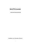
PV Grid-connected Inverter EHE-N1K5TL EHE-N2KTL EHE-N3KTL EHE-N4KTL EHE-N4K6TL User and Installation Manual Version: V3.0:2012 The copyright belong to EHE This document involves the proprietary and confidential information about PV grid-connected inverter of EHE It strictly prohibited to disclose the document by duplicating, photocopying, publishing online and in other forms without the company’s permission. EHE reserves the right to change details in this publication without notice. History of Versions Version Date Author 1.0 11-03-11 Liu Yan 1.1 11-06-10 Liu Yan 1.2 11-08-08 Liu Yan 1.3 11-12-29 Liu Yan 3.0 12-02-16 Liu Yan Approval MaZhibao MaZhibao Jun Yao Jun Yao Yao Jun 1 Comment Original release Electrical wiring way modification Increasing function information Inverter structure modification User manual version upgrade Table of Contents 1 Manual Instruction ........................................................................ 1 1.1 Applicability........................................................................... 1 1.2 Precautions........................................................................... 1 1.3 Symbols Used ....................................................................... 1 1.4 Tools Used in Inverter Installation .......................................... 3 2 Safety Instructions and Specifications ......................................... 4 2.1 Safety Instructions ................................................................ 4 2.2 Specifications........................................................................ 4 3 The Introduction of EHE-N TL Series PV Inverters ....................... 6 3.1 Introduction of Product .......................................................... 6 3.2 Features of EHE-N TL Series PV Inverters ............................. 7 4 Structure of EHE-N TL Series Circuit ............................................ 8 5 Installation .................................................................................... 9 5.1 Safety Instructions ................................................................ 9 5.2 Installation Preparation........................................................ 10 5.2.1 Inspection before Installation ....................................... 10 5.2.2 Requirement for Installation Conditions ........................ 10 5.2.3 Installation Direction .................................................... 12 5. 3 Installation of Inverter......................................................... 13 6 Electrical Connection and Commissioning................................. 16 6.1 Electrical Connection Steps ................................................. 17 6.2 Connecting Terminals at Bottom of Inverter .......................... 19 6.3 Selection of Cables for Electrical Connection ....................... 20 6.4 Grid Side Electrical Connection ........................................... 21 6.4.1 Consideration for Grid Side Electrical Connection ........ 21 6.4.2 Connect Inverter to Grid .............................................. 22 6.5 DC Side Connection Steps................................................... 25 6.5.1 Connecting Inverter to PV Array ................................... 25 6.5.2 Inverter Input Parallel Connection ................................ 28 6.6 Communication Connection ................................................. 31 2 6.8 Commissioning.................................................................... 37 6.8.1 Verify before Commissioning ....................................... 37 6.8.2 Inverter Commissioning ............................................... 37 7 Disassembling and Installation................................................... 38 7.1 Safety Instruction ................................................................ 38 7.2 The Installation and Backout of Cover Panel ........................ 39 7.3 The Disassembling and Installation of Connector ................. 40 8 Man-Machine Exchange System ................................................. 43 8.1 LCD Panel .......................................................................... 43 8.2 Function of Push-Button ...................................................... 44 8.3 LCD Screen Display ............................................................ 44 8.3.1 Initialization Interface .................................................. 44 8.3.2 Screen Display of Operating Parameters...................... 47 8.3.3 Fault-Screen Display ................................................... 49 8.4 LCD Screen Backlight Control.............................................. 51 8.5 Statistics of Total Generating Capacity and Time .................. 51 9 Troubleshooting .......................................................................... 52 9.1 Troubles and Processing ..................................................... 52 6.6.1 RJ45 Connector Wiring................................................ 31 6.7 Inverters with Three Inverters Per Phase ............................. 36 10 Appendix A ................................................................................ 54 11 Appendix B ................................................................................ 57 11.1 Quality Assurance.............................................................. 57 11.2 Contact Us ........................................................................ 57 3 1 Manual Instruction 1.1 Applicability This manual includes the description regarding the troubleshooting in process of transportation, installation, maintenance and operation of the following EHE-N TL inverters: ● EHE-N1K5TL ● EHE-N2KTL ● EHE-N3KTL ● EHE-N4KTL ● EHE-N4K6TL Please keep this manual in a convenient place for future reference. 1.2 Precautions This manual is for qualified electricians. The tasks described in this manual may be performed by electrically qualified persons only. 1.3 Symbols Used The following types of safety precautions and general information are used in this manual: "Warning" indicates the matter that the user must strictly followed, otherwise, it may endanger the personal safety or cause damage to the property. "Notice"indicates the important information for the user to optimize the PV system. 1 Symbols on the Inverter: Symbol Description DC AC Ground Protection Suggest of security considerations Beware of dangerous electrical voltage The inverter operates at high voltages. All work on the inverter may only be carried out by qualified personnel. Beware of hot surface The inverter can become hot during operation. during operation. Avoid contact CE mark The inverter complies with the requirements of EC guidelines. the applicable TUV mark The inverter complies with the requirements of the Equipment and Product Safety Act in Europe. 2 1.4 Tools Used in Inverter Installation Inverter installation and wire installation will need the following tools, You also can choose the right tools according to your own experience. 2 1 3 4 6 5 1、 Crimping plier 2、 Crimping plier 3、 Electric drill (Suggest specification: ф8) 4、 Socket wrench (Suggest specification: 14) 5、 Straight screwdriver (Suggest specification: M2) 6、 Cross screwdriver (Suggest specification: diameter 5) 3 2 Safety Instructions and Specifications Please read this manual carefully before starting installation and operation. Any damage to the equipment caused due to failure to comply with the descriptions in this manual in installation or operation will be beyond the scope of the company’s quality guarantee. 2.1 Safety Instructions Warning! The EHE-N TL series PV grid-connected inverters can only be operated by qualified personnel. Do not touch the live components of the inverters when the inverter is in operation. Please pay attention to all the safety instructions listed in this manual. Warning! Make sure that the DC input voltage should never exceed 520V. Over higher voltage will cause damage to the device. 2.2 Specifications The proper transportation, storage, assembly and installation as well as control and maintenance are required normally for safe operation. Warning! All operation and wiring works should be performed by professional electrical or mechanical engineers and all electrical installation shall be in accordance with the local electrical installation criteria. To ensure safe operation, the equipment isrequired to be properly grounded, use correct size of conductors and provide necessary short-circuit protection. 4 Warning! 在检 Please use a multimeter to measure the DC side and AC side voltage without fail before inspection and maintenance to ensure that the operation is performed with no voltage at both DC and AC sides. Warning! The solar cell arrays should be covered with opaque materials when installing the photovoltaic arrays during the day, otherwise the solar cell arrays will generate high voltage. Notice! The pictures in the manual are consult only, if deviate from the real object, according to the real object please. Please follow all the indications related to dangers, warnings and safety according to the requirements for operation and installation descriptions. 5 3 The Introduction of EHE-N TL Series PV Inverters The EHE-N TL series inverter is grid-connected inverter of high conversion efficiency without transformer. The EHE-N TL series grid-connected inverter enables maximum power output of solar panels and can convert and supply the output energy of solar panel to the power grid. 3.1 Introduction of Product The PV grid-connected generation system consists of PV arrays, grid-connected inverter, metering devices and distribution system (as shown in Fig. 3-1). The solar energy is converted into DC energy through solar cell array and then the DC energy is converted into sinusoidal wave AC voltage of the same frequency and phase with that of the grid, of which a part supplies power to the local load and the rest of the power is fed to the grid. Fig. 3-1 PV Grid-connected system Notice! The PV grid-connected generation should start with permission from the local utility department and invite the professional personnel to perform the relevant operations. 6 3.2 Features of EHE-N TL Series PV Inverters ● ● ● ● ● ● ● ● ● Adopt advanced IGBT power module. High conversion efficiency; low temperature rise; low noise; long lifespan. MPPT>99.9%. Advanced multi-languages LCD display and powerful communication interfaces. Intergrated DC isolation switch(optional). Extended MPP voltage range. Advanced anti-islanding technology. Perfect system protection, high reliability. Moudular design, easy to install, operate, maintain. 7 4 Structure of EHE-N TL Series Circuit Fig. 4-1 and Fig. 4-2 are block diagrams for internal functions of an EHE-N TL series inverter. MPP tracker to ensure that maximum power from PV arrays can be utilized. DC switch can cut input of the PV arrays. Boost circuit raises input DC voltage. Then H4 full bridge inverter circuit converts DC power to AC power. Meanwhile inverter is equipped with protective circuit to guarantee itself safely operation that can trigger AC relay if required. Fig. 4-1 Schematic diagram of EHE-N1K5TL/EHE-N2KTL Fig. 4-2 Schematic diagram of EHE-N3KTL/EHE-N4KTL/EHE-N4K6TL 8 5 Installation 5.1 Safety Instructions The installation, operation and maintenance of EHE-N TL series inveters must be carried out strictly according to the following specifications and instructions: ● Check the inverter carefully first for damage during transportation, if any problem is found, please contact Anhui EHE New Energy Tech. Co., Ltd. or the transportation company. The inverter grid-connected power generation should start with ● permission from the local utility department and the relevant operations should be carried out by professional personnel. All electrical connections must be in accordance with local electrical ● installation criteria. Don’t touch other parts in the cabinet except the connecting terminals ● in installation. Make sure that, the circuit breakers at both DC and AC sides are in ● open state before carrying out electrical connection. Make sure that the circuit breakers at both DC and AC sides are open. ● At least 5 minutes later, use a multimeter to measure the voltage at DC and AC sides before carrying out equipment maintenance to ensure that the maintenance must be conducted with no voltage at both DC and AC sides. 9 5.2 Installation Preparation 5.2.1 Inspection before Installation The product has been tested and checked carefully before transportation, but damage may be caused during transportation, therefore, the product should also be checked carefully before installation. If any damage is found, please contact EHE or the transportation company. Please keep well the photos taken at the damaged parts and we’ll provide you with best and fastest services. 5.2.2 Requirement for Installation Conditions Warning! ● ● ● ● ● ● The temperature will be increasing when the inverter is operating properly, therefore, do not install the inverter at a flammable or explosive place or a place where the flammable or explosive materials are stored. Do not install the inverter in a place where there is a risk of explosion. The inverter of IP65 protection class can be installed outdoor. Do not install the inverter in a place exposed to direct sunlight, otherwise, it may lead to higher temperature in the inverter resulting in derated operation, even overhigh temperature resulting in inverter temperature fault. The installation place selected should be solid enough to support the inverter weight for a long period. The site for inverter installation must be clean and the ambient temperature must be maintained within -25 to +60 °C. The inverter must be installed in a place convenient for observation and maintenance. Tne inverter uses natural cooling mode and the installation site selected should ensure the minimum installation spacing between the inverter and the fixed object and the nearby inverters to ensure an good ventilation. 10 40cm Direction minimum spacing above 60cm below 50cm sides 40cm 60cm 40cm 50cm Fig. 5-1 Minimum spacing of adjuscent installations Warning! The installation of EHE-N TL series inveter in a higher salt spray environment is prohibited. 11 5.2.3 Installation Direction 1. The inverter should be installed vertically or titled backwards with a maximum angle of 10°. 2. Do not install inverter tilted forwards. 3. Never install the inverter horizontally. 4. The installation height of inverter should be convenient for operation and reading out of the LCD displayed information. √ × √ × Fig. 5-2 Installation directions 12 5. 3 Installation of Inverter 1. Drill holes in the selected installation position according to the size and shape of sheet metal for installation of accessories. See the Fig. below for an installation example. When drilling, please drill at least two horizontal holes and two vertical holes, and the distance between two vertical holes should be at least 100mm. 2. The suggesting diameter of hole is 8+1/-0, the depth is 60+5/-0. When drilling, keep the drill vertically to the wall without shaking to avoid the holes tilting. Fig. 5-3 Installation holes of EHE-N1K5TL/EHE-N2KTL Fig. 5-4 Installation holes of EHE-N3KTL/EHE-N4KTL/EHE-N4K6TL 13 3. Fix installation sheet metal in the located holes with bolts. Fig. 5-5 Installation of bolts 4. Lock down the bolts, make the bolts cling to the wall. Fig. 5-6 Effect of Installation the bolts 14 5. Hang the inverter onto the installation sheet metal. Fig. 5-7 Installation of the EHE-N TL Notice! Fix the inverter on the rock or panel with the toggle bolt or screw is not permitted. Notice! Anhui EHE would provide the bolt which suitable for the installation on the concrete wall. If the inverter is fixed on the wooden wall, please choose suitable bolt to finish the installation, the bolt length should be enough and penetrate the 1/2 depth of the walls. 15 6 Electrical Connection and Commissioning The electrical connection should be carried out immediately when the installation is completed. When making electrical connection, special attention should be paied to the following operating specifications: Warning! Any improper operation and installation may cause fatal injury to operator. Only qualified electrical personnel can perform the wiring installation work. Before electrical connection, please make sure that the AC side and DC side are uncharged. The PV array open-circuit voltage set should not exceed 520V! Notice! The inverter can start grid-connected operation only when the local utility department approved and the professional electrical personnel completed the installation and electrical connection. All electrical installations must be in accordance with local and national electrical codes. Notice! The wires and cables of appropriate size must be selected and firmly connected and well insulated. Warning! Do not switch on any breakers until the PV generator has been connected and all of the devices have been fixed. warning! Do not plug in or out any connectors when the inverter is charged. 16 6.1 Electrical Connection Steps Fig. 6-1 and Fig. 6-2 show the electrical connections between grid-connected inverter EHE-N TL and solar cell array as well as grid. User must add a DC circuit breaker at the input side of inverter; add an AC circuit breaker at the output side of inverter. And the requirement models of breakers as Table 6-1. Because of the inverter has with DC switch itself, if the distance between solar cell array and inverter is short, you also can not add DC circuit breaker. Fig. 6-1 Schematic diagram of electrical connection of EHE-N1K5TL/ EHE-N2KTL Fig. 6-2 Schematic diagram of electrical connection of EHE-N3KTL/ EHE-N4KTL/EHE-N4K6TL 17 Breakers DC Breaker AC Breaker Table 6-1 Requirement for Selection of Circuit Breakers Requirement model EHE-N3KTL EHE-N1K5KTL EHE-N2KTL EHE-N4KTL 600VDC,16A 600VDC,16A 600VDC,16A 600VDC,16A 2poil 4poil 2poil 4poil 400VAC,25A 400VAC,16A 400VAC,20A 400VAC,25A 18 EHE-N4K6TL 600VDC,16A 4poil 400VAC,25A 6.2 Connecting Terminals at Bottom of Inverter The input and output terminals are installed in the bottom of the inverter and include DC side input terminals and AC side output terminals, and RS485 communication terminals. Fig. 6-3 Connection terminals at bottom of EHE-N1K5TL/2KTLInverter Fig. 6-4 Connection terminals at bottom of EHE-N3KTL/4KTL/4K6TLInverter Terminals PV+/PV1+/ PV2+ PV-/PV1-/ PV2AC ON OFF COM1 COM2 Table6-2 Terminals Description Description PV array DC positive input terminals, connect with power grid by DC breaker PV array DC negativeinput terminals, connect with power grid by DC breaker AC output terminals, connect with power grid by AC breaker DC switch is ON DC switch is OFF WiFi /RS485communication interface(optional) Reserve 19 6.3 Selection of Cables for Electrical Connection The user can select cables used for electrical connection according to the following specifications. Wire DC positive input cable DC negative input cable GND wire Grid L wire Grid N wire Table 6-3 Specifications of Cables for Electrical Connection Requirements( AWG) EHE-N1K5TL EHE-N2KTL EHE-N3KTL EHE-N4KTL EHE-N4K6TL 12 12 12 12 12 12 12 12 12 12 12 12 12 12 12 12 12 12 12 12 12 12 12 12 12 20 6.4 Grid Side Electrical Connection 6.4.1 Consideration for Grid Side Electrical Connection You must install a separate line circuit breaker for each inverter in order to ensure that the inverter can be securely disconnected under load. And the requirement models of breakers as Table 6-1. Warning! When more than one inverter is connected to the same line circuit breaker, the protective function of the line circuit breaker is no longer guaranteed. It can result in a cable fire or the destruction of the inverter. ● Never connect several inverters to the same line circuit breaker. Warning! When a producer (inverter) and a consumer are connected to the same line circuit breaker, the protective function of the line circuit breaker is no longer guaranteed. The current from the inverter and the grid can accumulate to overcurrent which is not be detected by the line circuit breaker. · Never connect consumers between the inverter and the line circuit breaker without protection. · Always protect consumers separately. 21 6.4.2 Connect Inverter to Grid 1、Connecting of the wire of the Connector: Please connect the wire of the AC Connector according to the following steps: Operation Instruction Operation Demonstration Step 1: Using the straight screwdriver to separate the connector jacket and the wire body. Step 2: Losing the fastening nut at the jacket bottom. Step 3: Strip off the insulation from the 3 wires: L, N, GND. The length of stripped insulation is approximate 7mm. Plug the wire through nut and intermediate leave. Step 4: Plug the L, N wires into the L, N holes in the connector, the GND into the hole with mark” ”, and then tighten the screws. Remember the colors corresponding to different wires. 22 Step 5: Connect the intermediate sleeve and front-end wiring slots and tighten the nut in the direction opposite to that in step 1. The impression drawing 2、Making sure that the grid voltage is in the permitted voltage rage (185-260Va.c.). 3、 Making sure that AC-side circuit breaker is in open state. 4、 Plug the AC connector into the AC-side terminal at the bottom of the inverter, untile a sound indicating inseted in place is heared( Take EHE-N3KTL for example) . 5、 Connect the cables between AC circuit breaker and the grid. 23 Notice! The PE connection is adopted inside the inverter, making the machine jacket and the cover are grounded. 24 6.5 DC Side Connection Steps Warning! When carrying out connection of PV array and inverter, the PV array should be covered with transparent materials and the DC-side circuit-breaker should be disconnected, otherwise, the PV array may generate dangerous voltage. Notice! Make sure that the DC input voltage of the inverter should not exceed 520V! For two-input inverter, the selection of cables of the same sectional area is required to ensure that the balance between DC input groups is kept. 6.5.1 Connecting Inverter to PV Array 1、 Measuring the PV array's positive and negative in multimeter, make the polarity is correct. Moreover, make sure the PV array voltage doesn't exceed the maximum input voltage (520V). 25 Notice! If the machine damaged because that PV array voltage exceeds maximum DC input voltage of the inverter, it doesn't belong to warranty range. ● Do not connect the PV array, of which the open-circuit voltage exceeds maximum DC input voltage to the inverter. Inspect every system carefully before installation. ● 2、 Connecting of the wire of the Connector. Please connect the wire of the DC Connector according to the following steps: Operation Instruction Operation Demonstration Crimping plier Step 1: Unscrew the fastening nuts from the connector. Step 2: Strip off the insulation from the DC cable, The length of stripped insulation is approximate 7mm. Step 3: Crimp the exposed core part to the connector tube core with crimping pliers. 26 Crimping effect figure Step 4: Plug cable with tube core part through the fastening nut. Step 5: Plug the tube core into the wiring trough untile a sound indicating inseted in place is heared. Tighten the nut in a direction opposite to that in step 1. Effect figure 3、 Make sure that the positive and negative pole of PV array is connected rightly. 4、 Make sure that the DC-side switch and DC-side circuit breaker are in open state, plug the positive and negative connector into the corresponding terminal at the bottom of the inverter respectively. Note that he positive and the negative mustn't be misconnected ( Take EHE-N3KTL for example) . 27 5、 Plug the other input connectors into the corresponding inverter terminals in the same way. Notice! EHE-N1K5TL/EHE-N2KTL inverter has one PV array input. EHE-N3KTL/EHE-N4KTL/EHE-N4K6TL inverter has two string PV inputs. The system supports simultaneous connection of two groups of PV arrays of the same power. The power of each string of PV array for EHE-N3KTL inverter shall not exceed 1.65KW. The power of each string of PV array for EHE-N4KTL inverter shall not exceed 2.2KW. The power of each string of PV array for EHE-N4K6TL inverter shall not exceed 2.53KW. 6.5.2 Inverter Input Parallel Connection EHE-N3KTL/EHE-N4KTL/EHE-N4K6TL Inverter has two strings PV array input. System supports input of the two groups PV array which are in the same frequency. But some systems may feature a single array. When this is the case, the array may be connected to the No.1 DC input PV1 section alone provided that array current is less than the maximum capacity of one section. To avoid possible problems when determining panel electric insulation parameters, short the inputs PV1 and PV2. 1、Parallel method of Inverter internal Parallel method of Inverter internal, just is short the inputs of the second section (PV2) by connecting a cable to the suitable terminals on the inverter board. First remove the cover panel of the inverter. How to remove the panel can refer to “7.2 The Installation and Backout of Cover Panel”. After remove the cover panel you can find the PV1+、PV1-、PV2+、PV2terminals on the main PCB board as Fig. 6-5. Short the PV1+ and PV2+ terminals with suitable wires, and short the PV1- and PV2- terminals in the same way, as Fig. 6-5. 28 internal parallel Fig. 6-5 Effect of inverter 2、Parallel method of Inverter external Parallel method of Inverter external, then need to select a photovoltaic connectors as Fig. 6-6. PV Connector 1 PV Connector 2 Fig. 6-6 photovoltaic connectors Then connect the photovoltaic connector 2 to PV1+ and PV2+ of inverter, and connect the photovoltaic connector 1 to PV1- and PV2- of inverter, as Fig. 6-7. Fig. 6-7 Effect of inverter external parallel 29 Notice! EHE-N1K5TL/EHE-N2KTL Inverter has one string PV array input, no need to perform short circuit. EHE-N3KTL/EHE-N4KTL/EHE-N4K6TL Inverter have two strings PV array input, can make them short circuited in parallel. We recommend you select the “Parallel method of Inverter external” to parallel connect in order to easy operation. 30 6.6 Communication Connection When the inverter worked as stand alone communication, the connection between the inverter and the monitoring equipment can be performed by means of RJ45 connector. There are 2 routes connecting holes located at the external of the inverter. It does not matter whether it is no.1 or no. 2 inputing wiring connected to the RJ45 connector considering that they are connected in parallel. Outputing wiring connected to the monitoring equipment (computer). RJ45 connector Fig. 6-8 RJ45 Connector 6.6.1 RJ45 Connector Wiring Description of the RJ45 connectors pin# on the panel showing as below: Table 6-4 RJ45 connector Pin Signal Description # Name 1 VCC The positive polarity of WiFi modular. 2 Not Used Not Used 3 4 A Required for RS485 communication. 5 B Required for RS485 communication. Not Used 6 7 Not Used 8 GND The negative polarity of WiFi modular. 31 Notice! To make sure the communication quality, the communicating cable should the shielding wire. Sub-thread has weak anti-interference capacity, will result in the communication work abnormally when the machine is disturbed. For convenience, we suggest you buy the finished network cable as the communication connector. Follow step2 to step 4,connect the PIN 4 and PIN 5 of crystal head to communication interface A and B of the RS485. If you want to make the communication connector yourself,please follow the step1 to 4. 1. Processing of the connector wire Please crimping the RJ45 first crystal wire as following: Operation Instruction Operation Demonstration Crimping plier Step 1: Pull out the wire Step 2: Put the wire in order 32 Step 4: Insert the wire into the first crystal in order Step 5: Ready to compact Step 6: Compressed Step 3: Cut off the wire Effect figure 33 2、 Make the wire crimped with the first crystal through the waterproof terminal. connector into the corresponding connector on the inverter, 3、 Insert the fastening the nut 4、Refer to the description of the RJ45 pin, select the corresponding wires connect to the corresponding A, B communication. 6.6.2 Multicomputer Communication RJ45 connectors can be used to connect a single inverter or many inverters connected in a daisy chain. Maximum number of inverters that can be connected in daisy chain is 255. Recommended maximum length of this chain is 1200 metres. In case many inverters are connected in a daisy chain, it is necessary to assign an address to each unit. Please reference the document of User Manual of Solar Power Management System for how to set addresses. Notice! Any device is supplied with default address "10". Notice! Any device delivered with the “1” and “2” of S2 dip switch in the “OFF” position. When we perform the Multicomputer communication, we should make the "1”and “2” of S2 dip switch, which is in the LCD panel of the last unit in the ON position, the "1”and “2” of S2 dip switches, which are in the LCD panel of the rest units in the OFF position. The 7.2 cover panel's disassembling and installation show you how to open the machine cover. 34 The following diagram shows you how to connect many multiple units in daisy chain configuration. Fig. 6-9 Multicomputer communication Notice! Multicomputer communication is optional. If do not need it, we will use an end cap to close “COM1” up, and install RJ45 as an alternative. 6.6.3 WiFi Communication EHE-N TL Inverters with WiFi function, how to use please refer to the “WiEi Communication Module User Manual”. 35 6.7 Inverters with Three Inverters Per Phase Example for the thermal rating for a line circuit breaker in a photovoltaic power-generating system operated in parallel with the low-voltage grid. We assume a PV system with 9 EHE-N TL inverters, with three inverters per phase, as the Fig. 6-10 below. Fig. 6-10 Three inverters per phase Required technical information for the inverters used. 1. Maximum output current as table 6-5. 2. Maximum permissible fuse protection for the inverter as table 6-6. Table 6-5 Maximum output current Requirements EHE-N1K5TL EHE-N2KTL EHE-N3KTL EHE-N4KTL EHE-N4K6TL 6.9A 10A 15A 20A 23A EHE-N1K5TL 16A Table 6-6 Maximum permissible fuse Requirements EHE-N2KTL EHE-N3KTL EHE-N4KTL 15A 25A 32A 36 EHE-N4K6TL 32A 6.8 Commissioning 6.8.1 Verify before Commissioning PV arrays The PV array should be checked before operation of the inverter to ensure that the positive and negative mustn’t be misconnect, otherwise, the damage may be caused to the inverter. Make sure that the open-circuit voltage of photovoltaic array doesn’t exceed the required voltage. DC input Make sure that the DC terminals of the inverter are connected correctly and maintained consistent with the PV array. AC output Make sure that the AC-side of inverter is connected correctly to ensure that the AC-side circuit breakers of the inverter are in open state. 6.8.2 Inverter Commissioning After electrical connection, accord to the following steps, start EHE-N TL PV inverters. Make sure that DC and AC voltage of inverter are in permitted range. Make sure that the inverter is connected correctly to the grid. Make sure that the polarity of PV arrays is correct. Make sure that the AC and DC terminals are connected firmly. Switch on the AC-side circuit breakers. Switch on the DC switch on the Inverter,then switch on the DC-side circuit breakers. After the above steps are completed, when the grid normal and DC-side voltages are higher than 180V, the inverter shall start operating automatically. Warning! Please first switch on the AC-side circuit breakers, then switch on the DC switch on the Inverter,at last switch on the DC-side circuit breakers, or may result in equipment damage. 37 7 Disassembling and Installation 7.1 Safety Instruction Warning! Before open the inverter, please pay attention to the following: ● Making the AC-side and DC-side circuit breakers are in open state. ● Waiting for a few minutes to making sure the inverter is uncharged. Warning! If the inverter has equipped the DC-side switch, please make it switch on before inserting and pulling out of the DC-side connector. Warning! When the inverter is in a state of charged, please don't insert and pull out of any connector. Otherwise, it will cause the personal injury and equipment damage. Notice! Electrostatic discharging will cause damage to the inner parts of the inverter. We should carry out the antistatic measure before disassembling and installation. 38 7.2 The Installation and Backout of Cover Panel Because of repair or any other reasons, need disassemble inverter cover, for the better seal performanc, make sure that you are operating according to the following instruction. 1、When disassemble inverter cover, use the cross screwdriver, screw the cover screw in turn, and then disengage the grounding wire from the grounding screw of the inverter cover. 2、 When installation, first installation the grounding wire to the grounding screw of the cover. Then installation cover, use the cross screwdriver, the torque is 1.8±0.2N·M, lock the cover screw in turn. Ground Screw Fig.7-1 The reference picture of Installation and disassembly 39 7.3 The Disassembling and Installation of Connector The Disassembling and Installation of PV connector The professional tool, which is designed specifically for the DC side PV Connector, are necessary if the connected PV Connector need to be removed, as it can help to pull out the connected PV connectors easily. Please operate as following : Demonstration picture Operation instructions Professional tool for PV Connector Step 1: Putting the professional tools into the holes of the PV connector totally, as shown on the picture, the connectors are disengaged. Step 2: Remove the connector. 40 AC Side Electrical Connection The AC side connectors need to be removed by screwdriver. Please operate as following: Demonstration picture Operation instructions Straight screwdriver Step 1: Inserting the straight screwdriver into the hole as shown on the picture so that the connectors are disengaged. Step 2: Remove the connector. 41 Communication Connection Steps No professional tools required. Just unscrew the connector as shown on the picture. Demonstration picture Operation instructions Step 1: Unscrew the nut as shown on the picture. Step 2: Remove the connector. 42 8 Man-Machine Exchange System 8.1 LCD Panel The LCD panel of EHE-N TL series inverter is composed of the LCD screen, LED lights and a button, and the system can be easily monitored, as shown in Fig. 8-1. LCD screen LED Button Fig. 8-1 LCD panel The EHE-N TL series inverter is characterized by high degree of intelligentization that can start and stop operating everyday automatically without manual control. There are 3 LED lights in the LCD panel (as shown in Fig. 8-1) that tell us the operating states of inverter. The states indicated by each LED light are as listed in the following table. Table 8-1 Description of LED Lights LED Light Color Description Power Green Power indicator light comes on (It comes on when LCD panel supplies power) Running Green Grid-Connected Running light (The indicator light comes on when it runs normally) Fault Red Fault light (It comes on when a fault occurs and not removed) The indicators are described in detail as follows: 1) The power indicator light (green) shall come on when supplying power. 2) The three indicator lights shall come on simultaneously when the system is initializing and the master chip is operating, and the fault light shall go off when the inverter runs normally. 3) When an error occurs in communication, the fault light and the running 43 light shall flicker at the same time. 4) When other fault occurs, the fault light shall come on until the fault is removed. 5) The running light shall be on as long as the inverter is running properly. 8.2 Function of Push-Button After the system is powered on, the LCD screen display boot screen at first, then display initialize screen(see screen 1&2 below). Then, press the button and hold it untill the LCD screen become "screen 3"(see screen 3 below), can reset the cumulative generating time and cumulative generating capacity. When "screen 9" is end,press the buttons shortly to view the LCD screen display and press the button shortly and continuously to scroll the screen displays rapidly. 8.3 LCD Screen Display 8.3.1 Initialization Interface After the system is powered on, about 10 seconds later, the three indicator lights come on simultaneously and the boot screen displays as follows. EHE New Energy Screen 1 Boot screen Then the system initializes and displays the follow screen. When the screen display is over, the running and the fault indicator lights go out at the same time. Initialize Waiting... Screen 2 System initialize screen Then display the Screen 3: 44 Ground R Test …… Screen 3 Grounding resistance testing screen If the grounding resistance fault, then display the Screen 4: Ground R Err Screen 4 Grounding resistance fault If there is no grounding resistance fault, then display the Screen 5: RI Sensor Test …… Screen 5 AC leakage current sensor testing screen If the AC leakage current sensor fault, then display the Screen 6: RI Sensor Err Screen 6 AC leakage current sensor fault If there is no AC leakage current sensor fault, then display the Screen 7, the inverter is in grid state testing, countdown from 90 to 60, in about 30s. Grid V Test 90 Screen 7 The grid voltage testing screen If the grid voltage loss, then display the Screen 8, Wherein “Cod “ represents shutdown code, “Cau “ represents shutdown reason. Grid Off Cod 4 Cau 2048 Screen 8 The grid voltage loss 45 If the grid voltage is normal, the Inverter entered the countdown state, 60、 59、 … 3、 2、 1、 0, and display the Screen 9: Grid Waiting 60 Screen 9 The countdown screen Note that during the initialization interface start-up, if have fault, display the Screen 10; If the PV voltage fail to meet the start condition, then display the Screen 11. Stop Code 1 Screen 10 Fault screen PV-in Low Screen 11 The PV voltage low After the system initialize screens display completed, the equipment version information shall be displayed subsequently, including "2.21" indicating the LCD version No., "3964" indicating the version No. of inverter and “10" indicating the ID No. the program updates, they also follow to update. Ver: 2.21 3964 10 Screen 12 Version No. screen If the communication is normal,the equipment model and serial No. shall be displayed subsequently, the screen shall be displayed as follows (the EHE-N3KTL model is taken as an example): EHE-N3KTL SN 6450000001 Screen 13 The equipment model and serial No. screen 46 As Screen 14, if the inverter have DC bus ground fault, the Riso is “0”, otherwise the Riso is “20”. The Port is port number,if use WiFi communication, the default value of Port is “9760”, if not , the Port is “0”. The port number can be modified through webpage, how to modify please refer to the “WiEi communication user manual”. Riso Port 20MΩ 9760 Screen 14 Grounding fault of DC bus screen Screen 15 shows IP address, if use WiFi communication, the value of WiFi IP is the actual allocated IP address, if not , the WiFi IP is “0.0.0.0”. WiFi IP 169.254. 1. 1 Screen 15 WiFi IP address 8.3.2 Screen Display of Operating Parameters After screen 15 appears about 2 seconds, the following 7 screens shall be displayed in turn (screen 16 to screen 24). Each screen displays about 10 seconds. Temp: -MPPT- 38℃ -RUN- Screen 16 Temperature and operating status information Screen 17 Grid current and voltage information Screen 18 Current and voltage information of PV array1 I2in: 3.6A V2in: 350V Igrid: Vgrid: 5.2A 230V I1in: V1in: 3.6A 350V 47 Screen 19 Current and voltage information of PV array2 For EHE-N1K5TL /EHE-N2KTL inverters, screen 19 shall not be displayed. P1in: P2in: 1260W 1260W Screen 20 Input power information P1in: 1260W Screen 21 Input power information For EHE-N1K5TL/EHE-N2KTL inverters, screen 20 shall not be displayed on LCD screen, but screen 21. For EHE-N3KTL/EHE-N4KTL/EHE-N4K6TL inverters, screen 21 shall not be displayed on LCD screen, but screen 20. Pout: Fgrid: 2600W 50.0Hz Screen 22 Output information E-Day: E-Tot: 3.4kWh 76kWh Screen 23 Daily power and cumulative power information RunT-D RunT-T 2min 7h Screen 24 Daily time and cumulative time information If no button is pressed, and no fault, the screen shall return to screen 16 display and the above cycle shall continue. If the button is pressed, the screen shall return to screen 12 and the above cycle shall continue. If have fault, the inverter shall stop running and display screen 25. S-Cod is outage code,S-Cau is the reason for outage. S-Cod S-Cau 1 32 Screen 25 Outage reason inquires screen 48 Note that during the Inverter is running normally, the PV voltage is low or the grid voltage is loss, and then will display the Screen 11 or the Screen 8. If have any other faults, please see the Screen 25. 8.3.3 Fault-Screen Display When severel faults occur, e.g. four faults, the screen shall display the follow screen after Screen 24 or Screen 25. Faults: 4 Screen 26 Fault advisary display If no button is pressed, the screen shall display as Screen 26; if the button is pressed (shortly and continuously), the screen shall display four faults in turn, and then continue the process of above cycle so that the user can inquire about the necessary information for troubleshooting. When the button is released, there is still fault that finally remains as screen 26 displays. When the faults are removed, the display returns to nomal and repeats the above process. The specific fault is shown as follows: Fault111! Screen 27 Fault screen Fault110! Screen 28 Fault screen Fault109! Screen 29 Fault screen Fault108! Screen 30 Fault screen Note that if a communication error occurs, no matter what displays on the 49 current LCD screen, a fault tip will pop up and displays until the communication error disappears, then the fault indicator light flashes. If the button is pressed shortly at this time, shall view every LCD screen display. Then release button, the screen remain displays the screen as follows: Comm Error Screen 31 Communication error Table 8-2 below lists the cross-reference of fault susplays: Table 8-2 Cross Reference of Fault Displays Name of Fault Radiator overheating Temperature switch fault Array 1 over-current Array 2 over-current AC hard over-current Drive over-current Grid-connection over-current Inverter amplitude error Synchronous phase error Grid phase loss Grid frequency error Grid amplitude error Communication fault, RXD off-line Communication fault, TXD off-line DC bus undervoltage Temperature sensor fault Slave equipment initialization error DC soft over-voltage Array 1 over-voltage Array 2 over-voltage Capacitance neutral-point voltagefault DC bus ground fault AC leakage current sensor fault AC leakage current out-of-limit fault AC leakage current mutation fault The disequilibrium between AC sensor A and B AC sensor A failure AC sensor B failure 50 Screen Display Fault100! Fault101! Fault102! Fault103! Fault104! Fault105! Fault106! Fault107! Fault108! Fault109! Fault110! Fault111! Fault112! Fault113! Fault114! Fault115! Fault200! Fault201! Fault202! Fault203! Fault204! Fault205! Fault206! Fault207! Fault208! Fault209! Fault210! Fault211! Array 1 current sensor fault Array 2 current sensor fault The DC component over load of IA The DC component over load of IB The zero calibration fault of IA The zero calibration fault of IB Parallel arrays off-line Fault212! Fault213! Fault214! Fault215! Fault300! Fault301! Fault302! 8.4 LCD Screen Backlight Control When the power is on, the LCD backlight shall come on and the initialization is completed. When the inverter operates normally about 10 seconds, the backlight will go out. If the button is pressed, the backlight shall come on. If no button is pressed for 30 seconds, the backlight shall go out. 8.5 Statistics of Total Generating Capacity and Time The total generating capacity statistics include the total daily generating capacity and total cumulative generating capacity. The total daily generating capacity is calculated from 0 after restarting the inverter. The total generating time statistics include the total daily generating time and the total cumulative generating time. The total daily generating time is calculated from 0 after restarting the inverter. The total generating time measurement will be accumulated after installation. 51 9 Troubleshooting 9.1 Troubles and Processing Once a fault occurs, the fault light comes on, the LCD screen displays the current fault and at the same time, the inverter will be shut down. The following table lists the typical faults and corrective measures. Content of Fault Grid frequency error (Fault110!) Grid amplitude error ( Fault111!) Grid phase loss ( Fault109!) Grid-connection over-current (Fault106!) Array 1 over-voltage ( Fault202!) Table 9-1 List of Troubleshooting Fault Description and Troubleshooting The grid frequency exceeds the allowable limits. Once the grid frequency returns to normal, the inverter will recover grid-connected operation after five minutes. for proper connection. ● Check the grid for stable frequency. ● Check the grid Grid voltage exceeds permitted range. Once grid voltage re-normal, inverter will recover running after over five minutes. ● Check the grid for proper connection. ● Check the grid for stable voltage. Grid phase loss ● Check the grid for normal wiring. ● If this fault occurs frequently, please contact Anhui EHE New Energy Tech. Co., Ltd. The grid-side current exceeds the allowable limit wiring for short circuit, check the ● Check the grid inverter for interference sources nearby, if not, please restart the inverter. ● If this fault occurs frequently, please contact Anhui EHE New Energy Tech. Co., Ltd. The first input voltage at DC side is overhigh ● Operate the DC circuit breaker, disconnect the PV component from the inverter immediately. PV array open-circuit voltage. ● Measure the 52 Array 2 over-voltage ( Fault203!) Array 1 over-current ( Fault102!) Array 2 over-current ( Fault103!) AC leakage current sensor fault (Fault206! ) ● Check that the connection mode of PV meets the inverter requirement. component voltage at DC side is overhigh The second input ● Operate the DC circuit breaker, disconnect the PV component from the inverter immediately. PV array open-circuit voltage. ● Measure the ● Check that the connection mode of PV the inverter requirement. component meets The first input current at DC side is overhigh ● Operate the DC circuit breaker, disconnect the PV component from the inverter immediately. connection mode of PV component ● Check that the meets the inverter requirement. The second input current at DC side is overhigh ● Operate the DC circuit breaker, disconnect the PV component from the inverter immediately. connection mode of PV component ● Check that the meets the inverter requirement. AC leakage current sensor failure ● When inverter is starting or running,this fault restart the inverter. occurs, please ● If this fault occurs frequently, please contact Anhui EHE New Energy Tech. Co., Ltd. 53 10 Appendix A Technical Data EHE-N TL Model EHE-N1K5TL EHE-N2KTL EHE-N3KTL EHE-N4KTL EHE-N4K6TL Data PV input quantities: Max PV Power 1650W 2200W 4400W 5060W 3300W Max PV 520V Voltage Isc PV Current 12.5A 16.25A 2*16.25A 2*16.25A 2*12.5A Max Input 1×10A 1×13A 2×10A 2×13A 2×13A Current Number of 1 2 String Number of 1 2 MPPT MPP Voltage 125V-420VDC 125V-420VDC125V-420VDC 125V-420VDC 150V-420VDC Range MPPT >99% efficiency PV Start 180 VDC 180 VDC 180 VDC 180 VDC 180 VDC Voltage Nominal Input 165-420 VDC 165-420 VDC 165-420 VDC 185-420 VDC 185-420 VDC Voltage range Max Inverter Backfeed 0A Current to the Array AC output quantities: Power 1.5kW 2kW 3kW 4kW 4.6kW Nominal output 6.5A 8.7A 13A 17.4A 20A current (at 230 VAC) Max. output 6.9A 10A 15A 20A 23A current Operating Grid 49.5 Hz~50.2Hz Frequency Operating Grid 230VAC Voltage Current < 3% 54 THD(at nominal output power) ) Power Factor(at > 0.99 nominal output power)) Max Efficiency 96.50% 96.50% 96.80% 97.00% 97.00% European 95.50% 95.50% 95.80% 96.00% 96.00% Efficiency Standby Power Nighttime Power Consumption Grid < 7W 0.5W VDE0126-1-1 monitoring Mechanical Dimensions (W × H × D) 325×475×170mm 325×535×190mm (approx.) Weight (approx.) 14kg 14.5kg 18kg 18.5kg 19kg Conditions and safety Isolation Transformerless Personal protection Protective Class Ingress protection Cooling Insulation monitoring , integrated all-pole sensitive leakage current monitoring unit I IP65 Natural Ambient Temperature Rating Data logger Data communication interface Altitude Noise emission -25 to + 60°C -25 to + 60°C -25 to + 60°C -25 to + 60°C -25 to + 60°C (@45°C derated) RS485(RS232 ,WiFi optional) 2000m;above 2000m need derate operating <45dB 55 Compliance IEC 62103; EN 50178; IEC/EN 62109-1;IEC/EN 62109-2; IEC/EN61000-6-1:2007;IEC/EN61000-6-3:2007; IEC/EN61000-3-3 :2007;AS/NZS 3100: 2009; AS4777.2: 2005; 2005; 56 AS4777.3: 11 Appendix B 11.1 Quality Assurance Warranty Period The warranty period of the product is five years, and the contract shall prevail if otherwise specified in the contract. Evidence In the warranty period, the company requires customers to show the product purchase invoice and purchase date. At the same time, the mark on the product should be clearly visible otherwise the company has right to refuse to give quality assurance. Conditions The product found failure during warranty period, Anhui EHE New Energy Tech. Co., Ltd. will, free of charge, repair or replace it with new product. The failed product replaced should be returned to Anhui EHE New Energy Tech. Co., Ltd. The client should give reasonable time for Anhui EHE New Energy to repair the faulty equipment. When one of the following cases exists, the company has the right to refuse to give quality assurance: Transportation damage. Improper installation. Improper modifications. Incorrect use or inappropriate operation Operated in a harsh ambient environment beyond the conditions described in this manual. Damage caused due to abnormal natural environment. If the product size and parameters have changed, the latest information given by the company shall prevail without notice. 11.2 Contact Us If you have any question about EHE-N single-phase photovoltaic grid-connected inverter, please contact us, and we will be happy to give you answers 57