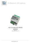
1
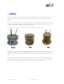
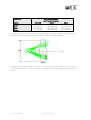
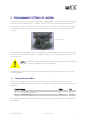
LED 155 LED Navigation Lantern User Manual Rev 1.42 (LEDFlasher) 19.1.2005 © Copyright 2005 Sabik LED 155 User Manual 1 DOCUMENT REVISION HISTORY Revision Date Comments 1.41 1.41 1.40 1.31 1.00 January 19th, 2005 March 22nd, 2004 December 9th, 2003 October 10th, 2002 June 6th , 2002 Default cable type changed, some other minor changes Luminous intensity values updated Updated to LEDFlasher Updated revision Initial document © Copyright 2005 Sabik Made By LED 155 User Manual LBM LBM LBM LBM LBM 2 CONTENT 1 GENERAL........................................................................................................................................................ 4 2 Delivery Configuration .................................................................................................................................... 5 2.1 Lantern Base ....................................................................................................................................................................5 2.2 Lantern Controller ...........................................................................................................................................................5 2.3 GPS Sync Unit.................................................................................................................................................................5 2.4 Cable Options................................................................................................................................................................5 2.5 GSM Remote Monitoring ............................................................................................................................................6 2.6 Optical Feedback System (OFBS) .............................................................................................................................6 2.7 Standard or Wide Lens.................................................................................................................................................6 3 LANTERN DESIGN.......................................................................................................................................... 8 4 SETTING POWER AND INTENSITY .............................................................................................................. 10 5 PROGRAMMABLE SETTINGS OF LANTERN ................................................................................................ 11 5.1 Setting up lantern, Normal Mode ........................................................................................................................... 11 5.2 Lantern Advanced Settings........................................................................................................................................ 12 6 TROUBLESHOOTING AND MAINTENANCE............................................................................................... 13 6.1 ERROR LED CODES (FLASHER SELF DIAGNOSTIC RED LED) ....................................................................... 13 6. GENERAL LAYOUT DRAWING .................................................................................................................... 14 7. WIRING DIAGRAM...................................................................................................................................... 14 7. WIRING DIAGRAM...................................................................................................................................... 15 Appendix A ........................................................................................................................................................... 16 Appendix B............................................................................................................................................................ 17 Appendix C ........................................................................................................................................................... 18 © Copyright 2005 Sabik LED 155 User Manual 3 1 GENERAL The LED 155 lantern is a new LED replacement for the standard 85mm and 155mm marine lanterns. The design is characterized with high efficiency, mechanically robustness and compatibility with signal standards. LED 155 is designed upon the Finnish MPV-3/LED lantern, which is capable of handling the ice pressure conditions in the Baltic Sea region – without additional ice protection. Whereby the new lantern is very sturdy and will endure considerable impact before destroyed. The lantern can be delivered with up to three optical heads (lenses and LED rings): Standard Duplex Triplex The Input voltage range for the lantern is 9 to 28 volts DC, and the intensity will remain constant within the input voltage range. This enables nominal light output at a 3 volt lower input voltage compared to standard 12 V marine lamps, which starts reducing intensity as soon as the input voltage drops below 12 volt. The lantern is supplied with a standard 4 wire cable (3+1). The wires are permanently marked with the following labels; B+ (Battery Positive), B- (Battery Negative), PV- and PE. The PV- signal is the negative signal from the solar panels. Wiring diagram is attached to the end of this document. © Copyright 2005 Sabik LED 155 User Manual 4 2 Delivery Configuration There are a number of options available for the lantern. When ordering, it is recommended that it is clearly indicated in the order the lantern configuration. 2.1 Lantern Base The lantern can be supplied with two types of bases; 3 holes equally distributed a 150mm diameter (for 85mm lantern replacement) 4 holes equally distributed a 200mm diameter (for 155mm lantern replacement) 2.2 Lantern Controller The default controller is the SmartFlasher for LED’s (also called the LEDFlasher). This is a new controller replacing the previous standard SmartFlasher and LEDDriver which has been the standard controller in previous LED lanterns. When ordering the lantern with the SmartFlasher the LED 155 User Manual 1.31 applies. 2.3 GPS Sync Unit For synchronizing lanterns using GPS signal, a GPS Sync Unit is available for the lantern. The GPS receiver is installed inside the lantern body and the GPS antenna is installed on the top of the LED 155 lantern hat. For more information about the GPS Sync Unit, please refer to the unit’s own manual. The GPS option is only available with the LEDFlasher. 2.4 Cable Options The lantern is supplied with a 1,5 meter 3 + 1 wire PUR cable as standard. Upon request, the lantern can also be supplied with a 3+1 polarity quick connector produced by Schaltbau. The details of this connector are: Type: Schaltbau M14 black with cover M1D black M1E-4P+PE (4-pin + PE) 4 x Pin: 1,58C 1,5 Au (or Ag) 1 x Receptacle: CB 1,58C 1,5 Au (or Ag) Pin Order: U+ on Pin 1, Ground on Pin 2, Sync Out on Pin 3 Lantern ground on Receptacle PE A corresponding supply cable with the matching Schaltbau termination is also available (has to be ordered separately). © Copyright 2005 Sabik LED 155 User Manual 5 2.5 GSM Remote Monitoring The lantern can be supplied with a built-in SmartLink Remote Terminal Unit (RTU) with integrated GSM modem. Only GSM SIM card needs to be added to enable the lantern to be a fully featured remote monitoring that can send status reports to end user or/and WebSCADA using GSM Short Message Service (SMS). The option is only available with the LEDFlasher. 2.6 Optical Feedback System (OFBS) The lantern can be supplied with an integrated OFBS unit that enables optical feedback monitoring of the LED’s. If the LED intensity degrades when the LED’s are aging, the OFBS system will be able to detect this and report back the level of degradation. Also, if the LED’s fails in one sector, the OFBS system will note this and report back to flasher. The OFBS unit is a standalone microcontroller unit with integrated firmware. At the end of the assembly of the lantern, each lantern is calibrated at the factory. As a part of the calibration procedure the starting value for each optical sensor is stored individually in the OFBS unit memory. When flashing night time the OFBS feedback level is reported back to flasher continuously. When operator wants to check the intensity level of the LED’s he can then access the reading from the lantern by Programmer. The LED actual level is reported back in the lantern Status list as a percentage of original (100%). 2.7 Standard or Wide Lens The lantern can be supplied with two different vertical divergences, standard or wide. The standard lens is used on lantern for fixed locations and on buoys with reasonable high stability and with less current. The wide lens is designed for usage on all floating stations in high current locations. The nominal vertical divergences for the lenses are listed in the table below. Lens Standard Wide Divergence @ 50% of peak Intensity 6° 10° Divergence @ 10% of peak Intensity 10° 20° The maximum luminous intensity and power consumption for each optical head (tier) of the lantern is: Standard Lens Colour Green Red White Yellow © Copyright 2005 Sabik Luminous Intensity and max Power Consumption Standard Duplex 120 cd @ 6W 240 cd @ 12W 120 cd @ 6W 240 cd @ 12W 100 cd @ 6W 200 cd @ 12W 90 cd @ 6W 180 cd @ 12W LED 155 User Manual Triplex 360 cd @18W 360 cd @18W 300 cd @18W 270 cd @18W 6 Wide Lens Colour Green Red White Yellow Standard 90 cd @ 6W 80 cd @ 6W 80 cd @ 6W 70 cd @ 6W Luminous Intensity and max Power Consumption Duplex 180 cd @ 12W 160 cd @ 12W 160 cd @ 12W 140 cd @ 12W Triplex 270 cd @18W 240 cd @18W 240 cd @18W 210 cd @18W The optical lens is made in Lexan™ polycarbonate and enables a vertical divergence which is equal to or higher than the standard 85mm lenses, and much higher than the existing 155 lanterns. In addition to this, the lens has light emission from the edges of the lens which is distributed evenly upwards – thus enabling the lantern to have the capability of being observed from high ships passing close to the lantern. © Copyright 2005 Sabik LED 155 User Manual 7 3 LANTERN DESIGN 1 8 2 9 3 10 5 4 11 6 7 The lantern consists of: Part 1 2 3 4 5 6 7 8 9 10 11 Description Top cover in aluminium Lantern Body aluminium LEDFlasher Optional Unit (GPS Synchro or SmartLink GSM) Data Connector to flasher c/w cover Optional Extemsion Unit Lantern base in aluminium Fresnel Lens LED ring Lens Gasket (2 pcs) Lantern venting (Gore PTFE membrane) © Copyright 2005 Sabik LED 155 User Manual Note Mounting of bird spikes Optional IrDA unit Encreases focal height Polycarbonate Lexan Including photocell 8 Other design features/details: Top cover is mounted with 6 pcs 10mm bolts Lens centering is by dual O-ring gaskets LED-PCB is connected to heat sink using special thermal film (GAP-PAD) The color code of the lantern can be found on the top blind plug The exact number of LED’s varies depending on color. The lantern has a built-in photocell which also is located on part 3 (the LED printed circuit board) inside the lens. When testing the photocell operation, it is important to cover the entire lens for example with a carton box in order to completely black out the photocell. There is a software controlled delay of approximately 30 seconds in the lantern before it switches from daytime mode to night operation, meanwhile the cover should not be removed (otherwise the lantern resets the delay counter) © Copyright 2005 Sabik LED 155 User Manual 9 4 SETTING POWER AND INTENSITY The lantern intensity can be adjusted from default 100% intensity down to 15% intensities by means of serial communication. The default factory setting is 100 % intensity. If a lower intensity is required, the intensity should be adjusted by means of programming the lantern. The control of the intensity is by means of Pulse Width Modulation (PWM) and the LED’s are always supplied with a nominal current that is 750 mA per tier. The LED nominal current should not be altered by the user (only available in Programmer Mk2 advanced mode) as a mean of adjusting the intensity; instead the Intensity setting should be altered. In the table below, you can find the various standard settings and the corresponding LEDFlasher Intensity set value required for the LED intensity: White Maximum Green Maximum Red Maximum Yellow Maximum © Copyright 2005 Sabik Power [W] 6,4W 5W 4W 3W 2W Standard Lens Intensity [cd] 125 100 80 60 39 Wide Lens Intensity [cd] 80 64 51 38 25 Power [W] 6W 5W 4W 3W 2W Standard Lens Intensity [cd] 138 116 93 70 46 Wide Lens Intensity [cd] 90 87 69 52 34 Power [W] 6,6W 6W 5W 4W 3W 2W Standard Lens Intensity [cd] 122 111 94 76 58 37 Wide Lens Intensity [cd] 80 73 63 51 38 25 Power [W] 6,6W 6W 5W 4W 3W 2W Standard Lens Intensity [cd] 90 82 69 56 42 27 Wide Lens Intensity [cd] 70 63 54 44 32 22 LED 155 User Manual 10 5 PROGRAMMABLE SETTINGS OF LANTERN The lantern functions are controlled by the LEDFlasher intelligent flasher unit that also incorporates a built-in solar panel charger allowing for up to 100W’s of solar panels to be connected directly to the lantern. Configuration of flasher is by means of serial communication to the flasher. The serial port of the flasher is located under the green cap between the two cable glands (or quick connectors depending on lantern versions). Data connector For configuration, the PC-Interface software (ProgLED) or the new portable Programmer Mk 2 unit can be used. For further details about using these configuration tools, refer to the appropriate instruction manuals for these devices. NOTE: The LEDFlasher ONLY works with the new Programmer Mk 2 portable unit. The old Programmer is NOT compatible with the new LEDFlasher. By default, the Programmer Mk 2 only displays the standard settings in the lantern that needs to be set prior to installation. 5.1 Setting up lantern, Normal Mode When the Programmer Mk 2 is connected to the lantern, the unit will automatically read the lantern configuration and display the settings to the user. In the default mode only the most commons settings are displayed: Flasher functions 1 Intensity 2 Photocell Threshold Level 3 Flashing Character Default 100 2,5 ISO 2 Unit % V 1+1=2s The settings can be modified and stored back to the lantern, where they will be stored in the EEPROM of the LEDFlasher. © Copyright 2005 Sabik LED 155 User Manual 11 5.2 Lantern Advanced Settings With the Programmer Mk 2 you can also access the advanced setting by pressing the dot-key three times. When in Advanced mode, all the LEDFlasher parameters can be modified. The table below outlines all the settings available in the lantern: A. Flasher functions 1 Intensity 2 Synchronising offset (delay) 3 Fixed light 4 Minimum battery voltage 5 Reconnecting voltage hysteresis 6 Photocell threshold level 7 Flasher serial number 8 Photocell override 9 Photocell override time-out 10 Sync Out / Error Out 11 Language 12 OFBS Minimum Level 13 LED Nominal Current B. Timer functions (seasonal lights) 1 Off period 2 Off period start date 3 Off period end date C. PV Charger functions 1 Cut-out voltage 2 Cut-in voltage (charging reconnecting voltage) 3 Boost charge hysteresis 4 Temperature compensation Default 100 0 Off 9 1,0 2,5 Individual Off 1 Day Sync Out 3 Unit % S V V V 70 2 0,75 1 % A Off Jan 1 June 1 14,4 13,8 0,5 30 V V V -mV/°C 1) LED Nominal Current Setting is depending on number of tiers. For the LED 155, the default setting is 0,75 ampere per tier, and this value should not be altered. 2) OFBS = Optical FeedBack System, only applies if the OFBS sensor is installed in the lantern 3) Sync Out / Error Out = alters the function of the Sync Out + terminal on flasher. In the default mode the flasher sends a Sync pulse to the Sync Out when flashing. When configured to Error Out the Sync Out pin will act as a logical alarm output that can be connected to a third party remote monitoring system Digital Input. © Copyright 2005 Sabik LED 155 User Manual 12 6 TROUBLESHOOTING AND MAINTENANCE The unit is designed to be maintenance free, except for battery replacement and lens cleaning. However, to maintain a good light output and long lifetime, it is advisable to go through the following list upon a service call to the lantern: General Maintenance • Cleaning the metal parts of the lantern and checking for any leakage • Cleaning and checking of the lens (usage of solvents prohibited) • Check that the light turns on/off and that the intensity appears to be normal. The photocell is located inside the optical lens so the easiest way to activate the lantern is to cover the lens and wait for a minimum of 30 seconds (the flasher has a built in delay) • All LED’s have the same intensity • Check, and if necessary replace the bird spikes Service Call • Check the cables • Check the flasher diagnostic (requires configuration device) • Check and register the battery voltage • Check the physical condition of the battery and replace if damaged 6.1 ERROR LED CODES (FLASHER SELF DIAGNOSTIC RED LED) Error LED codes are initiated when there are failures in the system. The codes are flashed in order of priority since only one error code can be shown at any time. 1. PROM Failure 2. Program Failure 3. EEPROM Failure 4. Short Circuit 5. Battery Low 6. Not in use 7. Lamp Failure 111110 101010 101110 110110 100000 101010 101000 111110 101000 101110 110000 100000 000000 101000 two short eclipses five flashes short flash, long flash three long flashes one flash three flashes two flashes 1= LED on 0= LED off The LED flashing frequency is one second; therefore the total LED message period is 12 seconds. © Copyright 2005 Sabik LED 155 User Manual 13 6. GENERAL LAYOUT DRAWING 7. Mounting Flange; Small Mounting Flange; Large © Copyright 2005 Sabik LED 155 User Manual 14 WIRING DIAGRAM © Copyright 2005 Sabik LED 155 User Manual 15 Appendix A LEDFLASHER 6-28 Configuration Parameters A. Flasher functions 1 Intensity 2 Synchronizing offset (delay) 3 Fixed light 4 Minimum battery voltage 5 Reconnecting voltage hysteresis 6 Photocell threshold level 7 Flasher serial number 8 Photocell override 9 Photocell override time-out 10 Sync Out / Error Out 11 OFBS Minimum Level 12 LED Nominal Current Default Value 100 0 Off 9 1,0 2,5 Individual Off 1 Day Sync Out 3 70 2 0,75 1 B. Timer functions 1 Off period 2 Off period start date 3 Off period end date Off Jan 1 June 1 V V V % A (seasonal lights) C. PV Charger functions 1 Cut-out voltage 2 Cut-in voltage (charging reconnecting voltage) 3 Boost charge hysteresis 4 Temperature compensation © Copyright 2005 Sabik Unit % S LED 155 User Manual 14,4 13,8 0,5 30 V V V -mV/°C 16 Appendix B LEDFLASHER Analogue Measuring and Status Partameter Unit Flasher 1 Battery voltage (loaded) 2 Battery voltage (unloaded) 3 Lamp illumination time (counter 1) 4 Flasher Real Time Clock 5 Photocell Day / Night indicator 6 Photocell level Charger 1 Charging status 2 Solar Panel Charging current 3 Charged Ah’s 4 Temperature Alarm 1 Self Diagnostics Error Code © Copyright 2005 Sabik V V h V mA Ah °C LED 155 User Manual 17 Appendix C LEDFLASHER TECHNICAL SPESIFICATIONS FLASHER FEATURES Input voltage Output Intensity Range Output LED current Output control Standby current Flash character Synchronizing Time accuracy Connection terminals Galvanic insulation Protection Programming Programmable settings Monitoring Monitorable measurements Programming devices Error signal Charging signal Photocell Solar Regulator Ampere hour counter Temperature sensor Serial communication Processor Temperature range Design features Dimensions Firmware © Copyright 2005 Sabik 9 .... 28 volt DC Programmable at steps of 1%, min 15% of full intensity Max 2,0 ampere (100 % duty cycle) PWM at 125 Hz less than 1,0 mA (daytime) Any desired light character, all IALA and any non standard. Max flashes in group 20, max. length of flash 325 seconds, min. flash length 0,10 seconds Synchronizing port standard. Automatic configuration to Master or Slave. Running light, flip-flop or other special settings available ± 0,01 % 11 pieces screw terminals, silver coated brass > 2 Mohm to case Protected against reverse polarity and short circuit All parameters user programmable. 19 pieces Built-in. Data transferred by serial communication 12 values, analogue and status indicators PC-computer or Field Programmer Mk2 Flashing indicator red LED, 7 different codes Green indicator LED, turns on when solar panel circuit in operation Built-In or external. Programmable in 50 steps from 10 to 1.000 lux max 8 ampere ± 5 % accuracy Built-in. Accuracy ± 2 °C 4800 baud asynchronous 8 - bit, 4 MHz controller - 40 °C ... + 60 °C Fully enclosed. Galvanic insulated shell of black anodized aluminum 36 mm x ∅ 82 mm, weight 340 g On FLASH ROM. Can be upgraded via serial communication LED 155 User Manual 18