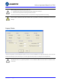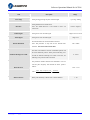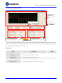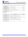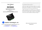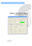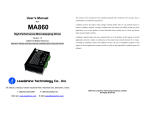
1
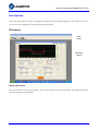
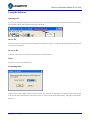
Software Operational Manual for ACS306 www.leadshine.com SM‐ACS306‐R20110826 ii Leadshine reserves the right to make changes without further notice to any products herein to improve reliability, function or design. Leadshine does not assume any liability arising out of the application or use of any product or circuit described herein; neither does it convey any license under its patent rights of others. Leadshine’s general policy does not recommend the use of its products in life support or aircraft applications wherein a failure or malfunction of the product may directly threaten life or injury. According to Leadshine’s terms and conditions of sales, the user of Leadshine’s products in life support or aircraft applications assumes all risks of such use and indemnifies Leadshine against all damages. ©2011 by Leadshine Technology, All Rights Reserved Change Log SM‐ACS306‐R20110826 Revision Date Changes Version 2011-8-26 Original Create SM-ACS306-R20110826 iii Table of Contents Introduction ..................................................................................................................................................................... 1 Workspace ............................................................................................................................................................... 1 Menus and Toolbar .......................................................................................................................................... 1 Using the Software .................................................................................................................................................. 3 Opening a file .................................................................................................................................................. 3 Save a file ........................................................................................................................................................ 3 Save as a file.................................................................................................................................................... 3 Close................................................................................................................................................................ 3 Connecting Drive ............................................................................................................................................ 3 Property Window............................................................................................................................................. 4 Current Loop Tuning Window......................................................................................................................... 6 Position Loop Tuning Window........................................................................................................................ 7 Scope ............................................................................................................................................................. 11 Error Log Window......................................................................................................................................... 12 Configuring the Drive ................................................................................................................................................... 13 Current Loop Tuning ............................................................................................................................................. 13 Tuning the 1st Position Loop Parameters............................................................................................................... 19 Tuning the 2nd Position Loop Parameters.............................................................................................................. 26 Contact Us..................................................................................................................................................................... 32 SM‐ACS306‐R20110826 Software Operational Manual for ACS306 Introduction The ProTuner for ACS306 is a software tool designed to configure and tune the Leadshine digital servo drive ACS306. The user can tune the current loop and adjust the position loop parameters in this software. Workspace Menu Toolbar PID Tuning Window Menus and Toolbar Menus and toolbars are at the top of the workspace. You can click menu bar to view the pull-down menu. The toolbar below the menu offers the most frequency used commands. SW‐ACS306‐R20110826 1 Software Operational Manual for ACS306 Menu File -> Drive -> Pull Down Toolbar Function Open Open a file Ctrl + O Save Save a file Ctrl + S Save As - Save as a file - Close - Close the current file - Exit - Exit from the software Ctrl + X Connect - Connect to drive Ctrl + N Properties Current Loop Position Loop Set drive properties like I/O logic, motor parameters. Set current loop parameters Kp and Ki and test. Set position loop PID parameters and test. - - - Download to Drive Download all data to drive - Reset Drive Restore factory setting - Open Tools-> Short cut Scope the scope and check the measured current, position following - error and motor velocity. Help-> Error Log Check the error log. - User Manual on Web Hardware manual - Software Manual on Web Software manual About Leadshine ProTuner Software information SW‐ACS306‐R20110826 - 2 Software Operational Manual for ACS306 Using the Software Opening a file If you want to reload the configuration data from a file in the PC, click on the File->Open. The parameters in the software’s workspace will be updated. The file name will appear on the right of the tile bar. File Name Save a file Click Drive->Save to save the data of current workspace to the opened file. If there is no a file opened, the Save dialog box appears and you can type in the file name. Save as a file Click Drive->Save As to save the data in current workspace to a file and rename it. Close Click Drive->Close to close the current file. Connecting Drive Connect to Drive window appears when you open the software. You can open it by clicking Drive->Connect any time. Select the right serial port and click on the Open button. The software will try to connect to the drive and read the settings. It may take several minutes. Please wait. SW‐ACS306‐R20110826 3 Software Operational Manual for ACS306 Before clicking on the Open button, please make sure: ! Notice 1) The RS232 cable .has been connected between the drive and the PC’s serial port. 2) The drive has been powered on and the green LED is turned on. The motor is unnecessary connecting to the drive if you just want to change the parameters but not tuning. ! Caution Do not connect or disconnect serial cable when the drive is powered on. The drive’s communication circuit may be damaged. Property Window Click Drive->Properties to open the Properties window. The user can set the command’s active edge, direction logic, active level of the Enable and Alarm signal, position following error, electronic gear and motor pole pairs according the motor and application. ! Notice The Motor Pole Pairs is very important parameter. .It is 2 for Leadshine’s BLM series motor and 4 for Leadshine’s ACM series motor. SW‐ACS306‐R20110826 4 Software Operational Manual for ACS306 Item Active Edge Description Setting the triggered edge of pulse command signal. Range Up-rising / Falling Setting Default motor rotate direction. Direction Note: The default direction is also related to motor coil Positive / Negative connections. Enable Signal Setting active level of Enable signal. High Level/ Low Level Alarm Signal Setting active level of Enable signal. High / Low Encoder Resolution for the Internal Pulse Generator. Encoder Resolution Note: This parameter is only used for the Internal Pulse 400 – 60000 Generator. It is 4 times of the encoder lines. The limit of the difference between commanded position and Position Following Error Limit the actual measured position. When position following error exceeds the Position Following Error Limit in the drive, the 0 – 65535 following error protection will be activated. This parameter includes numerator and denominator. You can scale the pulse frequency and calculate the motor speed as Electronic Gear follows: RPM 1/255 – 512/1 ( Pulse Input Frequence ) 60 ( Encoder Re solution ) 4 Motor Pole Paris SW‐ACS306‐R20110826 Numerator Deno min ator Motor poles divided by 2. Please refer to motor datasheet. 1 – 20 5 Software Operational Manual for ACS306 Current Loop Tuning Window Red Curve: Target Current of Step Test Green Curve: Actual Current of Step Test Click Drive->Current Loop to open the current loop tuning window. It is used to configure current loop parameters according to different motor. In the tuning window, the user can adjust the proportional gain, integral gain and test Current. Item Description Range Increase this parameter to make current rise fast. Proportional Gain determines the response of the drive to current setting command. Low Proportional Gain Proportional Gain provides a stable system (doesn’t oscillate), has low stiffness, and large current error, causing poor performances in tracking 1 – 65535 current setting command in each step. Too large Proportional Gain values will cause oscillations and unstable systems. Adjust this parameter to reduce the steady error. Integral Gain helps the drive to overcome static current errors. A low or zero value for the Integral Gain Integral Gain may have current errors at rest. Increasing the Integral 1 – 65535 Gain can reduce the error. If the Integral Gain is too large, the systems may “hunt” (oscillate) about the desired position. Test Current Test Button SW‐ACS306‐R20110826 The current amplitude for the step response. Click this button to activate the test. A target curve (red) and an actual curve (green) will be displayed on the screen for user analysis. 0.5 – 6 A - 6 Software Operational Manual for ACS306 Position Loop Tuning Window Digital Scope Pulse Generator Settings The 1st Dynamic Position Loop Parameter Scope Settings The 2nd Position Loop Parameter Click Drive->Position Loop to open the position loop tuning window. The user can adjust the position loop PID parameters and see the result by clicking the Start button. A build-in Pulse Generator performs trapezoid velocity motion and the Digital Scope displays the motor’s actual velocity, current and position following error. Digital Scope Item Description Range Current (A) Current axis of the digital scope. Unit: Amp. - Velocity (rpm) Velocity axis of the digital scope. Unit: rpm - Axis of Position following error in digital scope. Unit: Pulse - Position Error (p) SW‐ACS306‐R20110826 7 Software Operational Manual for ACS306 ProTuner Pulse Generator Settings Item Velocity (rpm) Acceleration (r/s^2) Distance (s) Interval Repeat Times Description Range Target velocity of Pulse Generator. 1– 65535 rpm Acceleration of Pulse Generator. 1 – 65536 r/s^2 Move distance of Pulse Generator. 1 – 65536 pulses Interval between the positive and negative move. 1 – 65535 ms Repeat times. 1– 65535 Scope Settings Item Current Position Error Velocity Trace Time SW‐ACS306‐R20110826 Description Actual measured current. Click to display it in the scope. Position following error. The difference between commanded position and the actual measured position. Actual measured velocity measured by the encoder. Ideally, this value should be as close as possible to the commanded velocity. Trace time of the digital scope. Range - - - 100 – 3000ms 8 Software Operational Manual for ACS306 The 1st Position Loop Parameters When the motor speed is > APPROX. 500RPM, the 1st position loop parameters take effect immediately for the motor behavior. Note: The 2nd position loop parameters will be used when the motor speed is < APPROX. 10 RPM. If the motor speed is between 10 to 500 RPM, the control parameter will switch to the 2nd position loop smoothly. Item Description Range Position Proportional Gain. Proportional Gain determines the response of the system to position errors. Low Proportional Gain Kp provides a stable system (doesn’t oscillate), has low stiffness, 0 – 65536 and large position errors under load. Too large Proportional Gain values will cause oscillations and unstable systems. Kvff Velocity feed-forward gain. Velocity feed-forward speeds up the system response. 0 – 65536 Position Derivative Gain. Derivative Gain provides damping by adjusting the output value as a function of the rate of change Kd of error. A low value provides very little damping, which may cause overshoot after a step change in position. Large values 0 – 65536 have slower step response but may allow higher Proportional Gain to be used without oscillation. Vp Vi Velocity Proportional Gain. Vp has similar effect as Kp but it is in the velocity loop. Velocity Integral Gain. It can be used to reduce the steady error of velocity when the velocity is settled. 0 – 65536 0 – 65536 Position Acceleration feed-forward gain. It is used to reduce Kaff the position following error during acceleration and 0 – 65536 deceleration. SW‐ACS306‐R20110826 9 Software Operational Manual for ACS306 The 2nd Position Loop Parameters When the motor speed is< APPROX 10 RPM, the 2nd position loop parameters take effect immediately for the motor behavior. Note: The 1st position loop parameters will be used when the motor speed is > APPROX. 500 RPM. If the motor speed is between 10 to 500 RPM, the control parameter will switch to the 1st position loop smoothly. Item Description Range Position Proportional Gain. Proportional Gain determines the response of the system to position errors. Low Proportional Gain Kp provides a stable system (doesn’t oscillate), has low stiffness, 0 – 65536 and large position errors under load. Too large Proportional Gain values will cause oscillations and unstable systems. Integral Gain. Integral Gain helps the control system overcome static position errors caused by friction or loading. The integrator increases the output value as a function of the position error summation over time. A low or zero value for the Ki Integral Gain may have position errors at rest (that depend on 0 – 65536 the static or frictional loads and the Proportional Gain). Increasing the Integral Gain can reduce these errors. If the Integral Gain is too large, the systems may “hunt” (oscillate at low frequency) about the desired position. Position Derivative Gain. Derivative Gain provides damping by adjusting the output value as a function of the rate of change Kd of error. A low value provides very little damping, which may cause overshoot after a step change in position. Large values 0 – 65536 have slower step response but may allow higher Proportional Gain to be used without oscillation. Vp Vi SW‐ACS306‐R20110826 Velocity Proportional Gain. Vp has similar effect as Kp but it is in the velocity loop. Velocity Integral Gain. It is used to adjust the steady velocity error when the velocity is stable. 0 – 65536 0 – 65536 10 Software Operational Manual for ACS306 Scope Click Tool->Scope to open the scope which is built inside the drive. You can check the actual measured velocity, current and position following error in this window. Item Description Range Current (A) Current axis of the digital scope. Unit: Amp. - Velocity (rpm) Velocity axis of the digital scope. Unit: rpm - Axis of Position following error in digital scope. Unit: Pulse - Actual measured current. Click to display it in the scope. - Position Error (p) Current Position Error Velocity Position following error. The difference between commanded position and the actual measured position. Actual measured velocity measured by the encoder. Ideally, this value should be as close as possible to the commanded velocity. Trace Time Trace time of the digital scope. Start/Sop button Click to turn on/off the scope. SW‐ACS306‐R20110826 - - 100 – 3000ms - 11 Software Operational Manual for ACS306 Error Log Window Click Tool->Error Log to open the error log window. This window shows both the present status of each error event and their history. Item Description Over Current Protection will be activated when the motor current is over 20A. Over Voltage Protection will be activated when the input voltage is over 40+/-1V. Low Voltage N/A. Phase Error N/A. Encoder Error Limit Error Following Error Protection will be activated when no encoder feedback signals or wrong encoder/hall sensor feedback signals connected to the ACS306. N/A. Protection will be activated when position following error exceeds the Position Following Error Limit. Brake Error N/A. Sampling Error N/A. EEprom Error N/A. Error Counter Display the No. of the errors. Erase All Errors SW‐ACS306‐R20110826 Clear the error log. 12 Software Operational Manual for ACS306 Configuring the Drive If it is the first time setup, you can follow the steps below to configure the drive. 1) Set motor related parameters such as motor pole pairs, encoder resolution and position following error. 2) Tune the current loop parameters according to motor. 3) Tune the 1st position loop parameters for the high-speed performance. 4) Tune the 2nd position loop parameters for the low-speed performance. 5) Save the changes to drive’s nonvolatile memory. ! The motor must be connected to the drive before trying to configure the drive. Notice Current Loop Tuning The ACS306’s current loop need to be tuned before normal operation in order to get optimize responses with different motors. Otherwise the motor will be easily stall or howls when power-up. Below is the tuning process for a NEMA 23 motor with 24VDC supply voltage. Step 1: Click Drive->Current Loop to open the tuning window. Set Test Current 1 and start the tuning with small Kp and “zero” Ki. Here we set Kp 2000. Initial Value Kp = 2000 Ki =0 Step 2: Click the Test button and the plot window will show two curves. The red one is target current and the green one is actual current. There is large gap between them in the scope. It indicates that a large Kp needs to be introduced. SW‐ACS306‐R20110826 13 Software Operational Manual for ACS306 Start Test: Proportional Gain = 2000 Integral Gain = 0 Step 3: Increase Kp to 3000 and click Test. The distance between target value and actual value is smaller but a higher Kp is still needed. ↑ Proportional Gain: Kp = 3000 Ki = 0 Step 3: Give Kp 5000, 7000, 9000 and click the Test button, respectively. The green curve is getting more and more close to the red curve. Intersection appears when we increase Kp to 6000. It indicates that you need to stop increasing Kp and back off. Our purpose is to make the green curve (the actual current) close to the red curve (the target). SW‐ACS306‐R20110826 14 Software Operational Manual for ACS306 ↑ Proportional Gain: Kp =5000 Ki = 0 ↑ Proportional Gain: Kp =7000 Ki = 0 SW‐ACS306‐R20110826 15 Software Operational Manual for ACS306 ↑ Proportional Gain: Kp =9000 Ki = 0 Intersection Step 4: Now the Kp is relatively good enough. But there is still distance between the green curve and the red curve when we use the mouse to zoom in the green curve. So we need to introduce Ki to reduce the distance or steady error at the constant part. It follows the same procedure as Kp. High Ki causes big vibration, system lag and makes the performance worse. The following figures show how to tune the Ki. Drag a triangle to zoom in SW‐ACS306‐R20110826 16 Software Operational Manual for ACS306 Zero Integral Gain: Kp =9000 Ki = 1 ↑Integral Gain: Kp =9000 Ki = 200 SW‐ACS306‐R20110826 17 Software Operational Manual for ACS306 ↑Integral Gain: Kp =Ki Ki = 400 Step 5: The current loop tuning is basically finished. You can continue to adjust Kp and Ki for better performance. Now the updated Kp and Ki is just stored in the driver’s RAM. They will be lost when we power off the driver. Don’t forget to click Drive->Download To Drive to store the changed value to the drive’s nonvolatile EEPROM. ! You can reduce the Kp if the motor’s noise can not be accepted for the application. Notice Save all the changes to the drive’s non-violated nonvolatile memory. SW‐ACS306‐R20110826 18 Software Operational Manual for ACS306 Tuning the 1st Position Loop Parameters Click Drive->Position Loop to open the tuning window. The follow example demonstrates the tuning of the 1st position loop base on a NEMA23 motor with 24VDC input. ! The motor should be installed to the machine and connected to load before the position loop tuning. Notice ! Caution Move the load to the middle of the axis and make sure (40000/Encoder Resolution) turns of motor shaft will not hit anything. Otherwise, please reduce the distance setting in the pulse generator. Before tuning the 1st position loop parameters, set pulse generator parameter as the following figure. We select the actual velocity and position following error to be displayed in the digital scope. Trace Time affects the display length of the curve. Here we select 1200ms. Pulse Generator and Scope Settings in this Example: Velocity = 1200rpm, Acceleration = 200r/s^2, Distance = 40000Pulse, Repeat Times = 1 Check the Velocity and Position Error Curve, Trace Time = 1200ms SW‐ACS306‐R20110826 19 Software Operational Manual for ACS306 The pulse generator will generate the following command trapezoid velocity profile. It takes 100ms to make the motor to accelerate from 0 to 1200 rpm. Velocity(RPM) 1200 900 600 300 0 -300 -600 -900 -1200 Commanded Trapezoid Velocity Curve Our purpose is to get the highest system stiffness but lower motor noise. The actual measured velocity should be similar as the commanded velocity curve. However, sometimes we need to trade off between them because high proportional gain leads to big overshoot and vibration. In this example, we start with small proportional gain then increase it. We will stop increasing when the motor noise can not be accepted. The Kaff and Kvff (Feed-forward gain) will be increased to further reduce the position following error if necessary. The tuning procedure is shown as follows: ①Kvff = 0, Kd = 100, Vi =0, Kaff = 0, Small Vp and Kp ②Vp↑ , motor noise begins, Vp↓ ③Kp↑ , motor noise begins , Kp↓ ④Kaff↑, Kvff↑, Kd↑ (If necessary) Step 1: Set Vp = 100, Vi = 0, Kp = 500, Kaff = 0, Kd = 0. The initial value is depending on supply voltage, motor and reflected load inertia. The above valuses may not suitable for your system. Please adjust them according to different symptom as follows: Decrease Vp/Kp if the motor generates big noise. Increase Vp/Kp if the drive’s red LED blinks (Protection mode). Tip: Giving an external torque by rotating the motor shaft (or moving the load) manually is good way to check whether the Vp and Vd are suitable or not. If it is hard to rotate/move and the motor generates big noise, you should lower down Vp/Kp. If it is easy to rotate/move and even the drive goes into protection mode (the red LED blinks), you should increase Vp/Kp. Encoder Servo Motor Observe the motor noise/vibration when increasing loop gain Press the Start button to start the test. The motor shaft will move (40000/Encoder Resolution) turns in two directions. Several seconds later the actual measured velocity and position error curve are displayed in the scope as follows. We see that the position error is large and the velocity curve is very bad when comparing to the commanded one. SW‐ACS306‐R20110826 20 Software Operational Manual for ACS306 Green Curve: Actual Measured Velocity. Pink Curve: Kp = 500, Vp = 100, Position Following Error. Kvff = Kd = Vi = Kaff = 0 Step 2: Increase Vp until the actual velocity curve is like the commanded one. If the motor noise is large and can not be accepted, decrease it until it can be accepted. To activate the noise/vibration, sometimes you need to give a disturbance to the load by either clicking the Start button or trying to push/pull the load. In this example, we give Vp 400, 800, 1000 and find that the noise/vibration at Vp=1000 can be accepted. So we stop increasing Vp. Kp = 500, ↑Vp = 400, Kvff = Kd = Vi = Kaff = 0 SW‐ACS306‐R20110826 21 Software Operational Manual for ACS306 Kp = 500, ↑Vp = 800, Kvff = Kd = Vi = Kaff = 0 Kp = 500, ↑Vp = 1000, Kvff = Kd = Vi = Kaff = 0 SW‐ACS306‐R20110826 22 Software Operational Manual for ACS306 Step 3: Increase Kp to maximize the system stiffness or minimize the position error until the motor noise/vibration can not be accepted, following the same way as Vp. See the figures below. We see that the peak position error reduce from 350 to 180 when increasing Kp to 4000. ↑Kp = 1000, Vp = 1000, Kvff = Kd = Vi = Kaff = 0 Position Error = 350 ↑Kp = 4000, Vp = 1000, Kvff = Kd = Vi = Kaff = 0 Position Error = 180 SW‐ACS306‐R20110826 23 Software Operational Manual for ACS306 ↑Kp = 8000, Vp = 1000, Kvff = Kd = Vi = Kaff = 0 Position Error = 170 ↑Kp = 12000, Vp = 1000, Kvff = Kd = Vi = Kaff = 0 Position Error = 160 Now the system has been basically tuned. In the following step, the user can increase Kvff to further reduce the position following error if necessary. However, big noise may be introduced if high Kvff. Step 4: Increase the Kvff to 5000 and 10000. The position following error reduces to 80 and 30, respectively. See figures. SW‐ACS306‐R20110826 24 Software Operational Manual for ACS306 Kp = 12000, Vp = 1000, ↑Kvff = 5000 Kd = Vi = Kaff = 0 Position Error = 80 Kp = 12000, Vp = 1000, ↑Kvff = 10000 Kd = Vi = Kaff = 0 Position Error = 30 Remember that tuning the servo is to get satisfying performances, getting the best performances of the servo is a time consuming work. So if the servo performance can meet your application requirements, then the easier tuning way the better. Just like if the performances of the products can meet your application requirements, then the cheaper the better. Step 5: Don’t forget to click Drive->Download To Drive to store the changed value to the drive’s nonvolatile EEPROM. SW‐ACS306‐R20110826 25 Software Operational Manual for ACS306 Tuning the 2nd Position Loop Parameters Click Drive->Position Loop to open the tuning window. The follow example demonstrates the tuning of the 1st position loop base on a NEMA23 motor with 24VDC input. ! The motor should be installed to the machine and connected to load before the position loop tuning. Notice ! Caution Move the load to the middle of the axis and make sure (1000/Encoder Resolution) turns of motor shaft will not hit anything. Otherwise, please reduce the distance setting in the pulse generator. Before tuning the 2nd position loop parameters, set pulse generator parameter as the following figure. We select the actual velocity and position following error to be displayed in the digital scope. Trace Time affects the display length of the curve. Here we select 1200ms. Pulse Generator and Scope Settings in this Example: Velocity = 30rpm, Acceleration = 200r/s^2, Distance = 1000Pulse, Repeat Times = 1 Check the Velocity and Position Error Curve, Trace Time = 1200ms SW‐ACS306‐R20110826 26 Software Operational Manual for ACS306 The pulse generator will generate the following command trapezoid velocity profile. It takes 2.5ms to make the motor to accelerate from 0 to 30 rpm. Velocity(RPM) 120 90 60 30 0 -30 -60 -90 -120 Commanded Trapezoid Velocity Curve Our purpose is to get the highest system stiffness but lower motor noise. The actual measured velocity should be similar as the commanded velocity curve. However, sometimes we need to trade off between them because high proportional gain leads to big overshoot and vibration. In this example, we start with small proportional gain then increase it. We will stop increasing when the motor noise can not be accepted. The tuning procedure is shown as follows: ①Kd = 100, Ki =100, Vi = 0, Small Vp and Kp ②Vp↑ , motor noise begins, Vp↓ ③Kp↑ , motor noise begins , Kp↓ ④Kd↑, Ki↑(If necessary) Step 1: Set Vp = 400, Vi = 0, Kp = 1000, Ki= 100, Kd = 100. The initial value is depending on supply voltage, motor and reflected load inertia. The above valuses may not suitable for your system. Please adjust them according to different symptom as follows: Decrease Vp/Kp if the motor generates big noise. Increase Vp/Kp if the drive’s red LED blinks (Protection mode) or the motor vibrates. Tip: Giving an external torque by rotating the motor shaft (or moving the load) manually is good way to check whether the Vp and Kp are suitable or not. If it is hard to rotate/move and the motor generates big noise, you should lower down Vp/Kp. If it is easy to rotate/move and even the drive goes into protection mode (the red LED blinks), you should increase Vp/Kp. Encoder Servo Motor Observe the motor noise/vibration when increasing loop gain Press the Start button to start the test. The motor shaft will move (1000/Encoder Resolution) turns in two directions. Several seconds later the actual measured velocity and position error curve are displayed in the scope as follows. We see that the position error is large and the velocity curve is very bad when comparing to the commanded one. SW‐ACS306‐R20110826 27 Software Operational Manual for ACS306 Green Curve: Actual Measured Velocity. Pink Curve: Kp = 1000, Vp = 400 Position Following Error. Ki= Kd = 100, Vi = 0 Step 2: Increase Vp until the actual velocity curve is like the commanded one. If the motor noise is large and can not be accepted, decrease it until it can be accepted. To activate the noise/vibration, sometimes you need to give a disturbance to the load by either clicking the Start button or trying to push/pull the load. In this example, we give Vp 600, 700,800 and find that the noise/vibration at Vp=800 can be accepted. So we stop increasing Vp. The velocity curve looks better. Kp = 1000, ↑Vp = 600 Ki= Kd = 100, Vi = 0 SW‐ACS306‐R20110826 28 Software Operational Manual for ACS306 Kp = 1000, ↑Vp = 700 Ki= Kd = 100, Vi = 0 Kp = 1000, ↑Vp = 800 Ki= Kd = 100, Vi = 0 SW‐ACS306‐R20110826 29 Software Operational Manual for ACS306 Step 3: Increase Kp to maximize the system stiffness or minimize the position error until the motor noise/vibration can not be accepted, following the same way as Vp. See the figures below. We see that the peak position error reduce a lot when increasing Kp to 2000. The velocity curve looks better. ↑Kp = 2000, Vp = 800 Ki= Kd = 100, Vi = 0 ↑Kp = 2500, Vp = 800 Ki= Kd = 100, Vi = 0 Now the system has been basically tuned. In the following step, the user can increase Kd to make the curve look more like the commanded one if necessary. However, the Kd is not sensitive. SW‐ACS306‐R20110826 30 Software Operational Manual for ACS306 Step 4: Increase the Kvff to 5000 and 10000. The position following error reduces to 80 and 30, respectively. See figures. Kp = 2500, Vp = 800 ↑Kd = 1000 Ki= 100, Vi = 0 Remember that tuning the servo is to get satisfying performances, getting the best performances of the servo is a time consuming work. So if the servo performance can meet your application requirements, then the easier tuning way the better. Just like if the performances of the products can meet your application requirements, then the cheaper the better. Step 5: Don’t forget to click Drive->Download To Drive to store the changed value to the drive’s nonvolatile EEPROM. SW‐ACS306‐R20110826 31 Software Operational Manual for ACS306 Contact Us China Headquarters Address: 3/F, Block 2, Nanyou Tianan Industrial Park, Nanshan District Shenzhen, China Web: http://www.leadshine.com Sales Hot Line: Tel: 86-755-2641-7674 (for Asia, Australia, Africa areas) 86-755-2640-9254 (for Europe areas) 86-755-2641-7617 (for Europe areas) Fax: 86-755-2640-2718 Email: [email protected]. Technical Support: Tel: 86-755-2641-8447, 86-755-2641-8774, 86-755-2641-0546 Fax: 86-755-2640-2718 Email: [email protected](for All) Leadshine U.S.A Address: 25 Mauchly, Suite 318 Irvine, California 92618 Tel: 1-949-608-7270 Fax: 1-949-608-7298 Web: http://www.leadshineUSA.com Email: [email protected] and [email protected]. SW‐ACS306‐R20110826 32