1
UB-R03
Technical Reference Guide
Product Overview
This chapter
explains
the features
of the product.
Describes
features
and general
specifications
for the product.
Installation
This
chapter
explains
how to connect
the UB-R03
to the
Describes
setup
and instrallation
of the product
and peripherals.
TM printer and use it.
Utilities
This
chapter
the
utility
for and
setting
the UB-R03.
Describes
howexplains
to control
the
printer
necessary
information
when you develop applications.
Programming Samples
This
chapter
information
for programming.
Describes
howexplains
to handle
the product.
UB-R03 Specifications
This chapter explains the specification of the UB-R03.
Exchange from the UB-R02
This chapter explains how to replace the UB-R02 with the UB-R03.
M00002804
Rev. E
Cautions
• No part of this document may be reproduced, stored in a retrieval system, or transmitted in any form
or by any means, electronic, mechanical, photocopying, recording, or otherwise, without the prior
written permission of Seiko Epson Corporation.
• The contents of this document are subject to change without notice. Please contact us for the latest
information.
• While every precaution has taken in the preparation of this document, Seiko Epson Corporation
assumes no responsibility for errors or omissions.
• Neither is any liability assumed for damages resulting from the use of the information contained
herein.
• Neither Seiko Epson Corporation nor its affiliates shall be liable to the purchaser of this product or third
parties for damages, losses, costs, or expenses incurred by the purchaser or third parties as a result of:
accident, misuse, or abuse of this product or unauthorized modifications, repairs, or alterations to this
product, or (excluding the U.S.) failure to strictly comply with Seiko Epson Corporation’s operating
and maintenance instructions.
• Seiko Epson Corporation shall not be liable against any damages or problems arising from the use of
any options or any consumable products other than those designated as Original EPSON Products or
EPSON Approved Products by Seiko Epson Corporation.
Trademarks
EPSON and ESC/POS are registered trademarks of Seiko Epson Corporation in Japan and other
countries/regions.
MS-DOS®, Microsoft®, Win32®, Windows®, Windows Vista® and Visual Studio® are either registered
trademarks or trademarks of Microsoft Corporation in the United States and other countries.
ESC/POS® Command System
EPSON has been taking industry’s initiatives with its own POS printer command system (ESC/POS).
ESC/POS has a large number of commands including patented ones. Its high scalability enables users
to build versatile POS systems. The system is compatible with all types of EPSON POS printers (excluding
the TM-C100) and displays. Moreover, its flexibility makes it easy to upgrade the future. The functionality
and the user-friendliness is valued around the world.
2
The influence on the environment of radio wave radiation
❏ The Radio Frequency module that can be installed in this product radiates the same high frequency energy as some other high frequency devices but the level of the energy radiated
from it is suppressed so that it is much lower than the electromagnetic energy radiated from
radio equipment like cell phones.
❏ Under some situations and in certain environments, the use of this equipment is sometimes
limited by the owner of the building or a representative with responsibility for the group.
For example, it may be restricted in the following case:
• Use in an environment where it may cause interference with other devices and services.
❏ If you do not understand the radio device usage policy in a specific group or environment,
such as an airport, ask permission before turning on the power of this product.
The influence on the human body of radio wave radiation
The output power radiated from the Radio Frequency module that can be installed in this
product is much lower than the radiation limit specified in the safety standard. However, it is
best to avoid allowing this product to contact your body during usual operation. While using,
be especially careful not to touch the cover of the antenna.
Note about interference
❏ The Radio Frequency module that can be installed in this product generates, uses, and can
radiate radio frequency energy and, if not installed and used in accordance with the instruction manual, may cause harmful interference to radio communications.
❏ If this equipment does cause harmful interference to radio or television reception, which can
be determined by turning the equipment off and on, the user is encouraged to try to correct
the interference by one or more of the following measures:
• Reorient or relocate the receiving antenna.
• Increase the separation between the equipment and receiver.
• Connect the equipment into an outlet on a circuit different from that to which the receiver
is connected.
• Consult your dealer or an experienced radio/TV technician for help.
❏ Never disassemble or modify this product or the installed Radio Frequency module.
❏ Seiko Epson Corporation shall not be liable for interference to radio/TV resulting from
changes or modifications to this product or the installed Radio Frequency module not
expressly approved by Seiko Epson Corporation.
3
❏ Other radio equipment sometimes uses the same frequency band that this unit uses. To prevent radio wave interference with other radio equipment, pay attention to the following
matters when you use this product:
• The Radio Frequency module that can be installed in this product uses the Industrial
Scientific and Medical band (2.4 GHz), DS-SS modulation, and the interference distance
is 40 m.
• Other equipment that uses the same frequency band used by the Radio Frequency
module that can be installed in this product includes equipment for industry, science
and medical treatment, microwave ovens, HomeRF, and radio and other broadcasting
equipment (both ones that require a license and ones that do not require a license).
1. Confirm that radio and other broadcasting equipment are not used nearby before using
this product.
2. When trouble occurs, for example, if the Radio Frequency module causes problems such
as radio wave interference, consult your dealer.
4
Note about security
This section describes security concerns when using a wireless LAN by using the Radio
Frequency module that can be installed in this product.
Security is important for the protection of the user’s privacy
A wireless LAN has the advantage that information can be exchanged by using radio waves
instead of a cable. However, radio waves are not confined to a cable and can be received in a
fairly wide area and through obstacles such as walls, so if security is not used, the following
problems may occur.
Communication data can be received by stealth.
A third person can receive private communication data by intercepting the radio waves
intentionally. Such a person could receive items such as the following:
• Personal information, such a an ID and password or credit card number
• The contents of e-mail.
• Data which is communicated between the PC and printer.
Illegal access
A third person can access the network and cause damage such as the following:
• Personal information and secret information can be removed.
• Invalid information can be sent as if it were from a legitimate user of the network.
• Intercepted communication contents can be re-written and sent.
• Data and the system can be destroyed by an electronic virus.
5
This product, the wireless LAN card, and the access point have security mechanisms to counter
these problems. If you use the security settings for this product, you can nearly eliminate these
problems.
In some cases, the wireless LAN equipment is not set up before it is sold to the user. Therefore,
to attempt to prevent security problems, always use all the security settings for the wireless
LAN equipment according to the manual.
The security functions, however, cannot guarantee 100% security. Please understand this
when you use this product.
Seiko Epson Corporation suggests that the security setting is set by the judgment and the
responsibility of user after understanding the possible problems resulting from using this
product without the security settings.
When you cannot set the security by yourself, please ask your dealer.
6
For Safety
Key to Symbols
The symbols in this manual are identified by their level of importance, as defined below. Read
the following carefully before handling the product.
You must follow warnings carefully to avoid serious bodily injury.
WARNING
CAUTION
Provides information that must be observed to prevent damage to the equipment or loss of
data.
• Possibility of sustaining physical injuries.
• Possibility of causing physical damage.
• Possibility of causing information loss.
Provides information that must be observed to avoid damage to your equipment or a
malfunction.
Provides important information and useful tips.
7
Warnings
WARNING
8
• To avoid risk of electric shock, do not set up this product or handle cables during
a thunderstorm
• Never insert or disconnect the power plug with wet hands.
Doing so may result in severe shock.
• Handle the power cable with care.
Improper handling may lead to fire or electric shock.
∗ Do not modify or attempt to repair the cable.
∗ Do not place any heavy object on top of the cable.
∗ Avoid excessive bending, twisting, and pulling.
∗ Do not place the cable near heating equipment.
∗ Check that the plug is clean before plugging it in.
∗ Be sure to push the plug all the way in.
• Be sure to use the specified power source.
Connection to an improper power source may cause fire or shock.
• Do not place multiple loads on the power outlet.
Overloading the outlet may lead to fire.
• Shut down your equipment immediately if it produces smoke, a strange odor, or
unusual noise.
Continued use may lead to fire. Immediately unplug the equipment and contact your
dealer or a Seiko Epson service center for advice.
• Never attempt to repair this product yourself.
Improper repair work can be dangerous.
• Never disassemble or modify this product.
Tampering with this product may result in injury or fire.
• Do not allow foreign matter to fall into the equipment.
Penetration by foreign objects may lead to fire.
• If water or other liquid spills into this equipment, do not continue to use it.
Continued use may lead to fire. Unplug the power cord immediately and contact your
dealer or a Seiko Epson service center for advice.
• If you open the DIP switch cover, be sure to close the cover and tighten the screw
after adjusting the DIP switch.
Using this product with the cover open may cause fire or electric shock.
• Do not use aerosol sprayers containing flammable gas inside or around this
product.
Doing so may cause fire.
Cautions
CAUTION
• Do not connect cables in ways other than those mentioned in this manual.
Different connections may cause equipment damage or fire.
• Be sure to set this equipment on a firm, stable, horizontal surface.
The product may break or cause injury if it falls.
• Do not use this product in locations subject to high humidity or dust levels.
Excessive humidity and dust may cause equipment damage or fire.
• Do not place heavy objects on top of this product. Never stand or lean on this
product.
Equipment may fall or collapse, causing breakage and possible injury.
• To ensure safety, unplug this product before leaving it unused for an extended
period.
Restriction of Use
When this product is used for applications requiring high reliability/safety such as
transportation devices related to aviation, rail, marine, automotive etc.; disaster prevention
devices; various safety devices etc.; or functional/precision devices etc., you should use this
product only after giving consideration to including fail-safes and redundancies into your
design to maintain safety and total system reliability. Because this product was not intended for
use in applications requiring extremely high reliability/safety such as aerospace equipment,
main communication equipment, nuclear power control equipment, or medical equipment
related to direct medical care etc., please make your own judgment on this product’s suitability
after a full evaluation.
9
About this Manual
Aim of the Manual
This manual is aimed to provide all the necessary information for development engineers to
develop, design, and install POS system, or to develop and design printer applications.
Manual Content
The manual is made up of the following sections:
10
Chapter 1
Product Overview
Chapter 2
Installation
Chapter 3
Utilities
Chapter 4
Programming Samples
Chapter 5
UB-R03 Specifications
Chapter 6
Exchange from the UB-R02
EMC Standards Applied
Product Name:
Model Name:
UB-R03
M239A
The following standards are applied only to the interface boards that are so labeled. (EMC is tested using the EPSON
power supplies and TM series printers.)
Europe:
CE marking
North America:
EMI:
FCC/ICES-003 Class A
WARNING
You are cautioned that changes or modifications not expressly approved by Seiko Epson Corporation could void your
authority to operate the equipment.
FCC Compliance Statement For American Users
This equipment has been tested and found to comply with the limits for a Class A digital device, pursuant to Part 15 of
the FCC Rules. These limits are designed to provide reasonable protection against harmful interference when the
equipment is operated in a commercial environment.
This equipment generates, uses, and can radiate radio frequency energy and, if not installed and used in accordance
with the instruction manual, may cause harmful interference to radio communications.
Operation of this equipment in a residential area is likely to cause harmful interference, in which case the user will be
required to correct the interference at his own expense.
FOR Canadian Users
This Class A digital apparatus complies with Canadian ICES-003.
Cet appareil numerique de la classe A est conforme a la norme NMB-003 du Canada.
RF Module
This equipment contains the following wireless module.
Manufacturer:
SEIKO EPSON CORPORATION
Type:
M238A
Product Name:
WI FI BOARD
This device complies with Part 15 of the FCC Rules and RSS-210 of the IC Rules. Operation is subject to the following
two conditions:
(1) This device may not cause harmful interference.
(2) This device must accept any interference received, including interference that may cause undesired operation.
11
USA
NOTICE
This device conforms to Part 15 of the FCC rules.
This device has been tested and found to comply with the limits for a Class B digital device, pursuant to Part 15 of the
FCC Rules. These limits are designed to provide reasonable protection against harmful interference in a residential
installation. This equipment generates, uses, and can radiate radio frequency energy and, if not installed and used in
accordance with the instruction manual, may cause harmful interference to radio communications. However, there is
no guarantee that interference will not occur in a particular installation. If this equipment does cause harmful
interference to radio or television reception, which can be determined by turning the equipment off and on, the user is
encouraged to try to correct the interference by one or more of the following measures:
-Reorient or relocate the receiving antenna.
-Increase the separation between the equipment and receiver.
-Connect the equipment into an outlet on a circuit different from that to which the receiver is connected.
-Consult the dealer or an experienced radio/TV technician for help.
This transmitter must not be co-located or operated in conjunction with any other antenna or transmitter.
FCC WARNING
Changes or modifications not expressly approved by the party responsible for compliance could void the user's
authority to operate the equipment.
Canada
This device conforms to IC, Low Power License-Exempt Radio Communication Devices (RSS-210).
The information such as Certification No., Model Name, and Manufacturer Name are described on the surface of the
module.
EUROPE
Hereby, SEIKO EPSON CORPORATION declares that this M239A is in compliance with the essential requirements
and other relevant provisions of Directive 1999/5/EC and 2004/108/EC.
France
In France, using the UB-R03 outdoors is prohibited.
Italy
In Italy, if used outside of own premises, general authorization is required.
12
CE Marking
DECLARATION of CONFORMITY
According to ISO/IEC Guide 22 and EN 45014
Manufacturer:
SEIKO EPSON CORPORATION
Address:
3-5, Owa 3-chome, Suwa-shi, Nagano-ken 392-8502 JAPAN
Representative:
EPSON FRANCE S.A.
Address:
Parc Technologique Europarc 60, Rue Auguste
Perret 94043 Creteil Cedex France
Declares that the Product:
Product Name: RF I/F BOARD
Model Name: M239A
Commercial Name: UB-R03
Conforms to the following Directives and Norms
R&TTE:
Directive 1999/5/EC
EN 300 328
EN 60950-1
EN 301 489-1
EN 301 489-17
EMC:
Directive 2004/108/EC
EN 301 489-1
EN 301 489-17
The printers in which board is installed do not conform to the following;
Directive 90/384/EEC EN 45501
The UB-R03 can be used only in the countries listed below:
Australia, Austria, Belgium, Canada, Czech, Denmark, Estonia, Finland, France, Germany, Greece, Hungary, Ireland,
Italy, Latvia, Lithuania, Luxembourg, Netherlands, NewZealand, Norway, Poland, Portugal, Slovakia, Slovenia,
Spain, Sweden, Switzerland, UK, USA, and Hong Kong.
13
Contents
The influence on the environment of radio wave radiation..............................................................3
The influence on the human body of radio wave radiation .............................................................3
Note about interference .......................................................................................................................3
■ Note about security ............................................................................................................. 5
Security is important for the protection of the user’s privacy ...........................................................5
■ For Safety .............................................................................................................................. 7
Key to Symbols........................................................................................................................................7
Warnings ..................................................................................................................................................8
Cautions ..................................................................................................................................................9
■ Restriction of Use .................................................................................................................. 9
■ About this Manual .............................................................................................................. 10
Aim of the Manual ...............................................................................................................................10
Manual Content ...................................................................................................................................10
■ EMC Standards Applied .................................................................................................... 11
FCC Compliance Statement For American Users............................................................................11
FOR Canadian Users ............................................................................................................................11
■ RF Module ........................................................................................................................... 11
USA .........................................................................................................................................................12
Canada.................................................................................................................................................12
■ EUROPE ................................................................................................................................ 12
France....................................................................................................................................................12
Italy.........................................................................................................................................................12
■ CE Marking ......................................................................................................................... 13
DECLARATION of CONFORMITY ..........................................................................................................13
■ Contents.............................................................................................................................. 14
Product Overview ........................................................................17
■ Features............................................................................................................................... 17
Supported OS .......................................................................................................................................18
Supported browser...............................................................................................................................18
Supported Protocols ............................................................................................................................18
■ Product Information ........................................................................................................... 19
Parts Name and Function ...................................................................................................................19
Usable Countries ..................................................................................................................................20
Supported TM Printers ..........................................................................................................................20
Communication Distance ...................................................................................................................20
Unpacking.............................................................................................................................................20
Space Required for Installation...........................................................................................................21
Environmental Specifications ..............................................................................................................21
Limitations..............................................................................................................................................21
14
Installation ....................................................................................23
■ Installation Precautions Cautions and Note.....................................................................23
■ Connect the UB-R03 to the TM Printer ...............................................................................24
■ How to Set the UB-R03 ........................................................................................................26
■ Setting using the USB connection .....................................................................................26
Procedure for setting the UB-R03 using the USB connection .......................................................... 26
The preparation of the computer and the acquisition of the information................................... 27
Setting of the UB-R03 ........................................................................................................................... 28
Confirming the operation ................................................................................................................... 36
■ Setting using the wireless LAN connection ......................................................................37
Procedure for setting the UB-R03 using the wireless LAN connection ........................................... 37
Preparation of the computer ............................................................................................................ 38
Printing a Dynamic Status Sheet ........................................................................................................ 38
Connection from the setting computer............................................................................................ 40
Setting of the UB-R03 ........................................................................................................................... 40
Confirming the operation ................................................................................................................... 44
■ Initializing the UB-R03 .........................................................................................................45
■ Changing of the Setting .....................................................................................................46
Change using a Web browser .......................................................................................................... 46
Change the setting using TMNet WinConfig V3 (USB connection) ............................................... 50
Change the setting using TMNet WinConfig V3 (By network) ........................................................ 51
Utilities ...........................................................................................53
■ Setting the TCP/IP Protocol in Your Operating System ....................................................53
Windows Vista ...................................................................................................................................... 53
Windows XP .......................................................................................................................................... 55
Windows 2000....................................................................................................................................... 56
■ TMNet WebConfig...............................................................................................................57
Activating the TMNet WebConfig...................................................................................................... 57
General Information ............................................................................................................................ 58
TCP/IP Information ............................................................................................................................... 60
SNMP Information ................................................................................................................................ 61
Wireless Setting..................................................................................................................................... 62
TCP/IP Setting ....................................................................................................................................... 64
SNMP Communication Setting........................................................................................................... 65
SNMP IP Trap 1 Setting ......................................................................................................................... 66
SNMP IP Trap 2 Setting ......................................................................................................................... 67
Administrator Setting ........................................................................................................................... 68
Password Setting .................................................................................................................................. 69
Reset...................................................................................................................................................... 70
■ Set the IP Address using PING ...........................................................................................71
Setting example................................................................................................................................... 71
15
Programming Samples ................................................................73
■ Method of Printing to the UB-R03 ...................................................................................... 73
■ Direct Printing by PORT 9100 ............................................................................................. 74
For Windows Console...........................................................................................................................74
For Linux .................................................................................................................................................75
■ Monitoring of the ASB status.............................................................................................. 76
■ More than one connection demands.............................................................................. 76
UB-R03 Specifications ..................................................................77
■ Software Specifications ..................................................................................................... 77
Supported Protocols ............................................................................................................................77
■ Network Parameter of the UB-R03 .................................................................................... 80
Setting of the network parameter of the UB-R03..............................................................................81
How to check the Mac Address.........................................................................................................81
■ System Bootup Time........................................................................................................... 82
Exchange from the UB-R02 .........................................................83
■ Comparison of the UB-R02 and the UB-R03 ..................................................................... 83
■ Procedure for exchanging ................................................................................................ 84
Confirm the setting of the wireless LAN interface (UB-R02) .............................................................85
Exchanging of the wireless LAN interface .........................................................................................86
Setting of the wireless LAN interface (UR-R03) ..................................................................................86
Confirm the operation .........................................................................................................................86
16
Chapter 1 Product Overview
Product Overview
This chapter explains the product overview.
Features
The UB‐R03 is installed in the TM‐series printers as an interface board to provide Wireless
Ethernet communications.
Wireless LAN
1
• IEEE802.11b compatible
• An infrastructure mode and an Ad‐Hoc mode are supported.
• Equipped with WPA/WPA2‐PSK, 64/128bit WEP
• Please prepare the access point (for the Infrastructure mode) or the computer for the wireless LAN (for Ad‐Hoc mode) for your system.
Network Function
• IPv4 capable. Not IPv6 capable.
• Supports DHCP/APIPA.
• SNMP capable. The status of the printer can be acquired by using SNMP.
Setting
• The setting from the computer for wireless LAN is possible the same as the wireless LAN interface (UB‐R02) as usual.
• The UB‐R03 has the USB connector only for the network parameter setting. The network parameter can be set through the USB connector. It is used only for the parameter setting, so it cannot be used for printing or other uses.
• Exclusive utility software (TMNetWinConfig V3) is needed to set through the USB
connector.
• The USB connector can be used only for setting the network parameter. The USB
connector cannot be used for other purposes, such as printing.
• You can check and set the parameter by using a Web browser.
• The setting utility TMNetWinConfig V3 is available. Please download it from the EPSON Web site and use it.
17
• When when you push the push button, the setting condition of the present network parameter is printed and you can check it.
Software
• The EPSON Advanced Printer Driver and the OPOS ADK are used for the UB‐R03.
Supported OS
• Windows Vista
• Windows XP
• Windows 2000
Supported browser
• Internet Explorer (Ver. 6.0 or later)
• Firefox (Ver. 2.0 or later)
Supported Protocols
Protocol
18
Application
IP, ARP, ICMP, UDP, TCP
Basic communications protocols for various functions.
LPR, TCP Socket Port
Protocol for printing.
DHCP, APIPA
Protocol for automatic settings of IP address, etc.
SNMP
Protocol for settings and watch.
HTTP
Protocol for using TMNet WebConfig.
TFTP
Protocol to update the firmware.
Chapter 1 Product Overview
Product Information
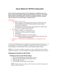
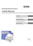
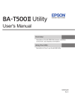
Parts Name and Function
Connector to printer
RF module
Antenna
1
Push button
USB connector
(Parameter Setting)
Push button
A push button is provided to perform the following functions.
• Status sheet printing
Push and hold the push button for three seconds or more when the TM printer is ready for printing (paper is set and the power supply is turned on); the network parameter status is printed.
• Setting initialization
Push and hold the push button and while turning on the power supply. Keep pushing the push button (about ten seconds) until the initialization start massage (Resetting to Factory Default) is printed. All settings are reset to the factory settings.
USB connector (Parameter Setting)
The UB‐R03 has a USB connector to set the internal parameters.
• To be connected with a USB cable to the computer on which the dedicated utility (TMNet WinConfig V3) is installed to set the internal parameters.
The USB connector can be used only for setting the network parameter. The USB connector
cannot be used other purposes, such as printing.
19
Usable Countries
The Radio Frequency module that can be installed in the UB‐R03 can be used in the following countries.
Country
Australia, Austria, Belgium, Germany, Luxembourg, Netherlands,
Switzerland, France, Italy, Greece, Spain, Portugal, Denmark, Finland,
Ireland, Sweden, UK, Czech, Estonia, Hungary, Lithuania, Latvia,
Poland, Slovenia, Slovakia, New Zealand, Norway, USA, Canada, and
Hong Kong.
Supported TM Printers
Any printer with an EPSON UIB interface can be used.
The UB‐R03 cannot be used with the RP‐U420.
For the following TM printers, check the printer firmware version. The UB‐R03 can be used when any of the listed firmware versions or later one is used.
Printer
Firmware version
TM-L90
Ver. 1.08ESC/POS, 1.07ESC/POS-J, 1.07ESC/POS-M
TM-T90
Ver. 1.09ESC/POS, 1.08ESC/POS-J, 1.06ESC/POS-M
TM-J7000/J7100
Ver. 1.07ESC/POS
TM-J7500/J7600
Ver. 1.04ESC/POS
TM-T70
Ver. 1.03ESC/POS, 1.02ESC/POS-J, 1.01ESC/POS-J(80)
TM-T88IV
Ver. 10.03ESC/POS, 10.03ESC/POS(58)
Communication Distance
• The communication distance is 30 meters {98 feet}.
• The communication distance depends on the surrounding environment of the electric wave, any obstacles, the placing and so on. Make a thorough evaluation when setting up.
Unpacking
• UB‐R03
• UB‐R03 Userʹs Manual
20
Chapter 1 Product Overview
Space Required for Installation
The position of the UB‐R03 is different for different printers. For example, when it is installed in the back of one model, it increases the depth of by printer by 30 mm(1.26ʺ). Take this into consideration for your installation.
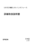
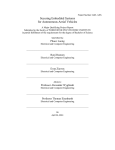
Environmental Specifications
Item
Temperature
Specifications
Operating
Conditions
0 to 50°C {32 to 122°F}, 10 to 90% RH non-condensation
(See the operating temperature and humidity range below.)
Storage
Conditions
-10 to 50°C {14 to 122°F}, 10 to 90% RH non-condensation
1
[%RH]
34°C, 90%
Relative humidity
90
40°C, 65%
65
Operating environment
range
50°C, 50%
10
0
34 40 50 [°C]
Ambient temperature
Limitations
The UB‐R03 has following limitations.
Limitations for the TM Printer
• It cannot be used with the RP‐U420.
• AC adapter Connection (Note about TM‐U200,210)
When combining and using the TM‐U200 or U210 and the UB‐R03, the PA, PB series AC adapter packed with the TM‐U200 and U210 cannot be used. Use the PS‐180.
21
Limitations for Transmission
• The transmission of the radio waves cannot be stopped. The only way to stop the transmission of radio waves is to turn the TM printer off.
• When printing a high volume of data such as graphics, the print speed is slower.
Limitation for Customer Display Use
When the UB‐R03 is connected, the DM‐D connector on the TM unit cannot be used.
Limitations Using USB Connector (Wireless Setting)
When the power supply is turned on under the following conditions, the wireless LAN function of the interface does not operate.
• The UB‐R03 is connected the computer with a USB cable.
• The TM printer is off‐line. (No paper or the cover open, etc.)
Unplug the USB cable or correct off‐line condition at the TM printer to operate the wireless LAN function.
The USB connector (for wireless setting) can be used only for setting to the network parameter.
It cannot be used other purposes, such as printing or setting the TM printer.
Restrictions on Using the Ad-Hoc Mode
Setting the Encryption Type
With the UB‐R03, WPA/WPA2‐PSK is not available in the Ad‐Hoc mode.
Although using the WebConfig function allows the Encryption Type “WPA/WPA2‐PSK” to be selected in the Ad‐Hoc mode, this setting actually is ignored. (In fact, the setting is the same as “no encryption.”)
Dynamic Status Sheet
When using the UB‐R03 in the Ad‐Hoc mode, printing a dynamic status sheet is subject to the following restrictions:
• Even if there is no host computer to connect to, “Connect” appears as the Link Status.
• Between power‐on and the time when the printer to connect is found, “0dBm” appears as the Signal Level. If the host computer connected to the TM printer discontinues communication, the value that had been obtained immediately before discontinuation of communication is held/appears.
22
Chapter 2 Installation
Installation
This chapter describes the UB‐R03 installation. The UB‐R03 is an interface board on which is installed the Radio Frequency module for Epson TM printers. The Radio Frequency module is installed on the UB‐R03 at the factory.
To set up the printer, install the UB‐R03 in the Epson TM printer and initialize the UB‐R03 to return it to its default setting. Set the PC to be able to communicate with the UB‐R03. Then change the setting of the UB‐R03 using the setting PC. The UB‐R03 can be set by using the dedicated utility TMNet WinConfig.
Installation Precautions Cautions and Note
WARNING
• Before installing, disconnect the Power Unit from the TM Printer (as well as turning the power switch off).
Even when the power switch is off, voltage is still present at some points on the circuit board. Changing components while the Power Unit is connected can cause damage to the UB‐R03 and the printer.
• A grounded wrist strap should be worn during installation to avoid damage from static electricity.
• To avoid damage from static electricity when the unit is removed, place it on an static‐safe surface such as conductive foam.
• Protect the unit from vibration and shock that could damage to the unit.
• Do not attempt to wire this product other than as described in this document. Improper wiring could cause damage, fire or explosion.
• Never disassemble or modify this product. Tampering with this product may result in injury, fire, or electric shock.
Because the default IP address for all the wireless printers is the same, you should power
on and configure only one printer at a time.
23
2
Connect the UB-R03 to the TM Printer
1
2
Confirm items in the pack. (“Unpacking” on page 20)
Remove the two screws of the universal interface connector of the TM
Printer and connect the UB-R03, and fix it with two screws.
Connector to the TM Printer
Two fixing screws
3
24
Set the DIP switch of the TM Printer. The interface of the TM printer must
be selected as “parallel” with the appropriate settings. If a TM printer
that can set the reset signal for pin 31 is used, set to “enable.” Refer to
the Technical Reference Guide for each TM printer for these settings for
details. Also, set the memory switches according to your needs.
Chapter 2 Installation
4
Power on the printer. Then, after waiting a little, hold down the push
button on the interface card for more than 3 seconds. The printer prints
the status sheet for the UB-R03. You can check all setting values
necessary for the network connection.
Push button
5
6
Turn the power switch of the TM Printer on while pressing the Feed
button. The printer prints current status of the printer on the paper.
2
Turn off the TM Printer.
25
How to Set the UB-R03
There are two ways to set the UB‐R03.
• Setting with the USB connection
Connect the computer to the USB connector (Parameter Setting) of the TM printer with the USB cable. This setting is possible without connecting to the network. Moreover, you can check the wireless LAN setting at any time, and if you make a mistake in the setting, you can correct it easily. This setting is recommended.
• Setting with the wireless LAN connection
Prepare the setting computer for wireless LAN and set it with the wireless LAN. If a setting that cannot be communicated in the wireless LAN environment of the computer is set, the connection is cut while setting and you cannot check the setting. Also the wrong setting can prevent communication.
When you set up the access point at the same time, set the access point in advance and
check that the UB-R03 operates correctly.
Setting using the USB connection
Setting the UB‐R03 by connecting the computer to the USB connector (Parameter Setting) using the USB cable.
Procedure for setting the UB-R03 using the USB connection
The preparation of the computer and the acquisition of the
information
Install the TMNet WinConfig V3 in the computer used for the setting,
and download the set up information.
Setting of the UB-R03
Connect the UB-R03 to the computer and set the wireless LAN setting.
Confirming the operation
Confirm the operation of the UB-R03 using a Web browser.
26
Chapter 2 Installation
The preparation of the computer and the acquisition of the information
Prepare the computer before setting up the UB‐R03.
Needs
• TM printer
: UB‐R03 is installed
• Computer for setting
: Windows Vista/XP/2000
• Computer for network
: Setting computer can be used
• Utility for setting
: TMNet WinConfig V3
• USB cable
Installing the TMNet WinConfig to the computer used for setting.
Download the TMNet WinConfig and install it to the computer.
(See “TMNet WinConfig Userʹs Manual” for information on how to install the TMNet WinConfig.)
2
Acquisition of the setting information
Acquire the following information from the network administrator.
Name
SSID(ESSID)
Security Setting
Explanation
Common
device for
network
This is set for each network of the SSID (ESSID)
wireless LAN. Set the same setting as the
access point.
√
This is a security setting and a cipher key. Set
the same setting as the access point for the
infrastructure mode.
Setting for
each
printer
√
Set the same setting as the computer for the
Ad-Hoc mode.
IP Address
Subnet Mask
Gateway Address
Set the IP Address not to duplicate other
devices in the network.
√
√
√
27
Setting of the UB-R03
Set the UB‐R03 according to the following steps.
1
2
3
28
Turn the power supply of the TM printer off, connect the computer to the
USB connector (Parameter Setting) with the USB cable.
Set paper in the TM printer and turn on it.
When the first connecting to the setting computer, the “Installing device driver software”
message is displayed, then the hardware setup is started automatically. Wait about one or
two minutes until the setting is completed. (For Windows Vista)
Boot the TMNet WinConfig V3 in the computer for setting.
Select [All Programs]-[EPSON TMNet WinConfig V3]-[TMNet WinConfig].
Chapter 2 Installation
4
The “TMNet WinConfig Ver.3.00” window is displayed. Select [USB] in the
Interface.
Confirm that the printer is displayed in the list.
2
5
Select the printer for setting and click the [Configuration] button.
6
The “Network Interface Card Properties” dialog box is displayed.
7
Select the [Wireless] tab.
When the printer is not displayed, click the [Search] button.
29
8
Set the wireless LAN.
The setting items depend on the communication mode (Ad-Hoc/Infrastructure).
For “Ad Hoc” mode
30
• Communication Mode
: Select “Ad Hoc.”(Default Setting: Ad Hoc)
• SSID
: Set the same value as the computer. The maximum is 32 alphanumeric characters.
(Default Setting: EpsonNetIBSS)
• Channel
: Select the channel. (Default Setting: 11)
• Security Settings
: Select “None” or “WEP.”
“WPA/WPA2” cannot be used.
WEP is recommended for setting. (Default Setting: None)
Chapter 2 Installation
For “WEP” Security Settings
• Input using hex
: Check the checkbox choosing the WEP Key to be input as a hexadecimal number.
• Active WEP Key
: Select the WEP Key you are using. Key 1 to Key 4
• WEP Key Length
: Select the length of WEP Key. 64 bit (40 bit)/128 bit (104 bit)
• WEP Key 1 to Key 4
: Input the WEP Key. The number of characters of WEP Key changes according to the setting.
For 64 bit (40 bit), ASCII 5 characters
For Hex 64 bit (40 bit), 10 places
For 128 bit (104 bit), ASCII 13 characters
For Hex 128 bit (104 bit), 26 places
31
2
For “Infrastructure”
32
• Communication Mode
: Select “Infrastructure.”
• SSID
: Set the same value as the computer. The maximum is 32 alphanumeric characters.
• Security Settings
: Select one of “None,” “WEP,” or “WPA/WPA2.”
Chapter 2 Installation
For “WEP” Security Settings.
• Input using hex
: Check the checkbox choosing the WEP Key to be input as a hexadecimal number.
• Active WEP Key
: Select WEP Key you are using. Key 1 to Key 4
• WEP Key Length
: Select the length of WEP Key. 64 bit (40 bit)/128 bit (104 bit)
• WEP Key 1 to Key 4
: Input the WEP Key. The number of characters of WEP Key depends on the setting.
For 64 bit (40 bit), ASCII 5 characters
For Hex 64 bit (40 bit), 10 places
For 128 bit (104 bit), ASCII 13 characters
For Hex 128 bit (104 bit), 26 places
For “WPA/WPA2” Security Settings
• PSK (Pre‐shared Key)
9
: Input the PSK (Pre‐shared Key). ASCII 8 to 63 characters
Select the [TCP/IP] tab.
33
2
settings such as the IP Address.
10 TCP/IP
The setting items are different for Manual and Automatic. Record the IP Address to use for
confirming the setting.
When you set the IP Address yourself, select “Manual.” When using the IP Address
allocated from the router by DHCP, select “Automatic.”
For setting the IP Address Manually
Set the IP Address, the Subnet Mask and the Default Gateway.
• Manual/Automatic
: Select “Manual.”
• Set using PING
: When setting the IP Address using the PING command from the network computer, check the [Set using PING] checkbox.
• IP Address
: Set the IP Address.
• Subnet Mask
: Set the Subnet Mask.
• Default Gateway
: Set the Default Gateway.
For setting the IP Address Automatically
• Manual/Automatic
34
: Select “Automatic.” Acquire the IP Address, the Subnet Mask and the Default Gateway from the DHCP server.
Even if you set the Subnet Mask and the Default Gateway, the value acquired from the DHCP is set.
Chapter 2 Installation
• Set using Automatic Private IP Addressing(APIPA)
: If the value cannot be acquired from the DHCP server, the IP Address is set automatically by checking the Set using Automatic Private IP Addressing (APIPA) check box. The Subnet Mask and the Default Gateway is set the setting value.
• Set using PING
: When setting the IP Address using the PING command from the computer of the network, check the [Set using PING] checkbox.
• Subnet Mask
: Set the Subnet Mask.
• Default Gateway
: Set the Default Gateway.
11 After setting the TCP/IP, click the [OK] button.
12 The confirmation dialog box is displayed. Click the [Yes] button.
2
13 The “Password” dialog box is displayed. Click the [OK] button.
14 The contents of the setting are transmitted to the UB-R03. It takes about
30 seconds to display the completion window. Click the [OK] button.
15 Confirm the setting on each window of the TMNet WinConfig V3.
16 When the setting is completed, remove the USB cable.
35
Confirming the operation
Confirm that the printer equipped with the UB‐R03 wireless LAN interface is connecting to the network. There are three confirmation methods.
• Confirm using a Web browser.
• Conform using TMNet WinConfig V3.
• Conform using the PING command from the command prompt.
This section describes how to confirm using a the Web browser.
1
2
Confirm that the network is running; then boot the computer of the
network.
Boot the Web browser and enter the IP Address for the UB-R03 in the
address bar. The “TMNet WebConfig” window is displayed.
Address: http://(IP Address of the UB-R03)/
Enter IP Address
3
36
If the “TMNet WebConfig” window is not displayed, connect the
computer for setting to the USB connector (Parameter Setting) with the
USB cable, then confirm the setting again.
Chapter 2 Installation
Setting using the wireless LAN connection
Prepare the setting computer for the wireless LAN and set it using the wireless LAN.
Procedure for setting the UB-R03 using the wireless LAN connection
The preparation of the computer
Install the TMNet WinConfig V3 in the computer used for the setting,
and download the setup information.
Printing a Dynamic Status Sheet
Print the Dynamic Status Sheet and conform the setting of the UB-R03.
2
Connection from the setting computer
Connect using the Ad-Hoc mode.
Setting of the UB-R03
Setting of the UB-R03.
Confirming the operation
Confirm the operation of the UB-R03 using a Web browser.
37
Preparation of the computer
Prepare the computer before setting up the UB‐R03.
Needs
• TM Printer
: The UB‐R03 installed
• Computer for setting
: Windows Vista/XP/2000
Computer equipped with wireless LAN function
• Computer for network
: Setting computer can be used
• Utility for setting
: TMNet WinConfig V3
Installing the TMNetWinConfig in the computer used for setting
Download the TMNetWinConfig and install it in the computer.
(See “TMNetWinConfig Userʹs Manual” for information on how to install the TMNetWinConfig.)
Acquisition of the setting information
Acquire the following information from the network administrator. (For details of the setting information, refer toʺAcquisition of the setting informationʺ on page 27.)
Printing a Dynamic Status Sheet
Print a Dynamic Status Sheet to confirm the setting of the UB‐R03.
When the printer is connected to the setting computer directly, the network mode should be the Ad‐Hoc mode.
If the status sheet says “Infrastructure,” initialize the setting of the UB‐R03. (Refer to ʺInitializing the UB‐R03ʺ on page 45)
38
Chapter 2 Installation
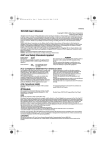
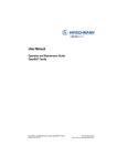
Printing a Dynamic Status Sheet
Power on the printer. Then, after waiting a little, hold down the push button on the interface card for more than 3 seconds. The printer prints the status sheet for the UB‐R03. You can check all setting values necessary for the network connection.
Push button
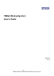
An example of a Dynamic Status Sheet
*** Dynamic Status Sheet ***
802.11b Interface
MAC Address
Hard Version
Soft Version
WLAN pri F/W
WLAN STA F/W
Allowed Channel
:xx.xx.xx.xx.xx.xx
:xx.xx
:xx.xx
:xx.xx.xx.xx.xx
:x.xx
:1-11
Wireless Status
SSID
Network Mode
Link Status
Access point
Channel
Transmission Rate
Signal Level
Noise Level
RTS Threshold
Fragment Threshold
AP density
Authentication
Encryption
Encryption Key
Socket Timeout
Disconnect Timeout
:EpsonNetIBSS
:Ad-hoc
:Connect
:xx.xx.xx.xx.xx.xx
:11
:Auto
:-41dbm
:N/A
:2347
:2346
:N/A
:Open System
:Disable
:N/A
:300
:5
TCP/IP Settings
IP Address
Subnet Mask
Default Gateway
DHCP
APIPA
PING
:192.168.192.168
:255.255.255.0
:0.0.0.0
:Disable
:Disable
:Enable
SNMP Settings
Community Name 1
Community Name 2
:public
:
2
Necessary item for the network setting
************************************
39
Connection from the setting computer
Connect the computer for setting to the TM printer by the wireless LAN. The setting of the wireless LAN of the setting computer is set for the Dynamic Status Sheet.
As for the setting method of the setting computer, refer to the manual of the computer
used.
• Network Mode (Ad‐Hoc)
• SSID (Ex: EpsonNetIBSS)
• IP Address (Ex: 192.168.192.2)
(Donʹt set the same address as the IP Address of the printer to the setting computer.
Example: If the IP Address is 192.168.192.168, the IP Address of the setting computer should be set to another number, such as 192.168.192.2. The same address (192.168.192.168) cannot be used.)
• Channel (Ex: 11 ch)
When you set up a TM printer equipped with more than one wireless LAN interfaces, turn
on only one printer. If more than one printer is turned on at the same time, the TM printer
cannot be set up.
At this stage, the TM printer can communicate with the setting computer.
Setting of the UB-R03
Set up the UB‐R03 according to the following steps.
1
40
Boot the TMNet WinConfig V3 of the setting computer.
Select [All Programs]-[EPSON TMNet WinConfig V3]-[TMNet WinConfig].
Chapter 2 Installation
2
The “TMNet WinConfig Ver.3.00” window is displayed. Select “Wireless” in
“Interface” and confirm that the printer is displayed in the list.
If the printer is not displayed, click the [search] button. If the printer is still not displayed,
the wireless LAN connection is not established. Confirm the setting of the setting
computer again.
2
3
Select the printer for setting and click the [Configuration] button.
4
The “Network Interface Card Properties” dialog box is displayed.
5
Select the [Wireless] tab.
41
42
6
Set the wireless.
7
Select the [TCP/IP] tab.
8
Set the IP Address.
(As for details of the setting, refer to "Set the wireless LAN." on page 30)
(As for details of the setting, refer to "TCP/IP settings such as the IP Address." on page 34.)
Chapter 2 Installation
9
After setting, click the [OK] button.
10 The confirmation dialog box is displayed. Click the [Yes] button.
11 The “Password” dialog box is displayed. Click the [OK] button.
2
12 The setting content is sent to the UB-R03. After a while, the completion
dialog box is displayed. Click the [OK] button.
At this stage, the wireless LAN of the UB‐R03 is changed. The connection with the setting computer is cut according to the setting item and it is not displayed in the “TMNet WinConfig V3” window. 43
Confirming the operation
Confirm that the printer equipped with the UB‐R03 wireless LAN interface is connected to the network. There are three confirmation methods.
• Confirm with a Web browser.
• Conform with TMNet WinConfig V3.
• Conform with the PING command from the command prompt.
1
2
Confirm that the network has been running, and boot the netword
computer.
Boot the Web browser and enter the IP Address for the UB-R03 on the
address bar. The “TMNet WebConfig” window is displayed.
Address: http://(IP Address of the UB-R03)/
Enter IP Address
If the “TMNet WebConfig” window is not displayed, print the Dynamic Status Sheet and
confirm the setting. When it is not possible to set it, initialize the UB-R03. Then perform
setting according the information from "Printing a Dynamic Status Sheet" on page 38.
44
Chapter 2 Installation
Initializing the UB-R03
The UB‐R03 setting can be reset to the default using the following method.
1
Set a roll paper for the TM printer to print.
2
Turn off the TM printer.
3
While holding down the Push button, turn the TM printer on.
Push the Push Button using an extended paper clip or a pen point.
Push Button
2
4
Wait about 10 seconds without letting the Push button up. A receipt as
shown below is printed.
Do not turn the printer off until the initialization is completed.
5
6
After about 20 to 25 seconds, a message notifying the completion of
initialization is printed.
After the completion message, a Dynamic Status Sheet is printed.
45
Changing of the Setting
There are three methods for changing the setting of the UB‐R03 connected with the network.
• Change the setting with a Web browser.
Settings can be changed by a computer on the same network. If you are changing many setting items, change them another way.
• Change the setting using TMNet WinConfig V3 (USB connection).
This method is similar to the initial setting procedure. It is suited for setting with other networks because the connection with the UB‐R03 is not cut.
• Change the setting using TMNet WinConfig V3 (By network).
It is suited for changing the setting in the same network.
Change using a Web browser
Change the setting of the UB‐R03 using a Web browser. It is suited for some changes in the same network. After setting of the UB‐R03, the TM printer should be reset. If the UB‐R03 is set to another network, the connection will be cut.
Change method
1
46
Boot the computer of the network.
Chapter 2 Installation
2
Boot the Web browser and enter the IP Address set for the UB-R03 in the
address bar. The “TMNet WebConfig” window is displayed.
Address: http://(IP Address of the UB-R03)/
Enter IP Address
2
3
Select the item in the configuration and change the setting.
Selection
47
4
When the setting is completed, click the [SUBMIT] button.
The set content should be reflected in the UB-R03 when you click the [SUBMIT] button of
each “TMNet WebConfig” window. If the window is switched without clicking the
[SUBMIT] button, the input contents are cleared.
[SUBMIT] button
5
48
When the setting is completed, the message is displayed. Turn off the TM
printer and turn on it again.
Chapter 2 Installation
Confirm after changing
After changing of the setting, boot the Web browser of the computer on the network and enter the IP Address of the UB‐R03 in the address bar.
Confirm that the “TMNet WebConfig” window is displayed.
Address: http://(IP Address of the UB-R03)/
Enter IP Address
2
49
Change the setting using TMNet WinConfig V3 (USB connection)
Connect the UB‐R03 to the setting computer with the USB connection, and change the setting from TMNet WinConfig V3.
This method is similar to the initial setting procedure. It is suited for setting with other networks because the connection with the UB‐R03 is not cut.
Changing method
For the details of the changing method, refer to ʺSetting using the USB connectionʺ on page 26.
Confirm after changing
After changing of the setting, boot the Web browser of the computer on the network and enter the IP Address of the UB‐R03 in the address bar.
For the details of the confirm, refer to ʺConfirm after changingʺ on page 49.
50
Chapter 2 Installation
Change the setting using TMNet WinConfig V3 (By network)
It is suited for changing the setting in the same network.
Changing method
1
2
Boot the computer of the network.
Boot the TMNet WinConfig V3. Select “Wireless” and then select the
printer to change the setting.
2
51
3
4
Click the [Configuration] button to display the “Network Interface Card
Properties” dialog box.
Change the setting. After setting, click the [OK] button.
Changing is completed.
Confirm after changing
After changing of the setting, boot the Web browser of the computer on the network and enter the IP Address of the UB‐R03 in the address bar.
For the details of the confirming, refer to ʺConfirm after changingʺ on page 49.
52
Chapter 3 Utilities
Utilities
Setting the TCP/IP Protocol in Your Operating
System
To set the IP address, you need to install the TCP/IP protocol in your operating system. How to set the TCP/IP protocol is explained for Windows Vista/XP/2000.
Windows Vista
1
Click the [View status] icon in the Control Panel.
3
53
2
3
The "Local Area Connection Status" dialog is displayed.
Click the [Properties] button.
The "Local Area Connection Properties" dialog is displayed.
Check whether the [Internet Protocol Version 4 (TCP/IPv4)] check box is
checked. If not, click the check box.
After the TCP/IP is installed, restart your computer and move on to the Installing
TMNetWinConfig section.
54
Chapter 3 Utilities
Windows XP
1
2
3
Click the [Network and Internet Connections] icon in the Control Panel;
then click [Network Connections].
Double-click the [Local Area Connection] icon. The “Local Area
Connection Status” dialog is displayed.
3
Click [Properties] and check whether the [Internet Protocol (TCP/IP)]
check box is checked. If not, click the check box.
After the TCP/IP is installed, restart your computer and move on to the Installing
TMNetWinConfig section.
55
Windows 2000
1
2
Double-click the [Network and Dial Set Up] icon in the Control Panel;
then click Local Area Connection Status.
Click [Properties] button and check whether the [Internet Protocol (TCP/
IP)] check box is checked. If not, click the check box.
After the TCP/IP is installed, restart your computer and move on to the Installing
TMNetWinConfig section.
56
Chapter 3 Utilities
TMNet WebConfig
TMNet WebConfig is a utility that allows you to make settings for the UB‐R03 using a Web browser.
(The screenshots used in this chapter were captured using Internet Explorer. If you are using another browser, the screenshots may differ from those of your browser, however, there is no difference in the setting items and procedures themselves.)
Supported browser
• Internet Explorer (Ver. 6.0 or later)
• Fire Fox (Ver. 2.0 or later)
Activating the TMNet WebConfig
Follow the procedure below to activate the TMNet WebConfig.
1
2
Turn on the computer that can establish wireless connection with the
UB-R03.
Start your browser and enter the IP address of the UB-R03. The TMNet
WebConfig will start.
3
Address: http://(IP Address of the UB-R03)/
Enter IP address
57
General Information
Item
Interface card
58
Explanation
Administrator
name
Shows the administrator name.
Location/Person
Shows the location or user name.
Model name
Shows the name of the interface card.
MAC address
Shows the MAC address of the UB-R03.
Software version
Shows the software version of the UB-R03.
Hardware
version
Shows the hardware version of the UB-R03.
Chapter 3 Utilities
Item
Wireless
Printer
Explanation
Communication
Standard
Shows the Communication Standard.
Network Mode
Shows the Network Mode.
SSID
Shows the SSID.
Channel
Shows the Channel.
Transmission
Rate (Mbps)
Shows the Transmission Rate.
Access Point
(MAC Address)
Shows the MAC Address of Access Point.
Signal Condition
Shows the Signal Condition.
Printer ID
Shows the printer ID.
Printer status
Shows the printer status.
3
59
TCP/IP Information
Item
60
Explanation
Get IP Address
Shows the method of setting the IP address.
Set using Automatic
Private IP Addressing
(APIPA)
Shows the APIPA setting.
Set using PING
Shows the IP Address using the PING (ICOMP Echo Request) command.
IP Address
Shows the IP address.
Subnet Mask
Shows the subnet mask of the IP address.
Default Gateway
Shows the default gateway.
Chapter 3 Utilities
SNMP Information
3
Item
Community
IP Trap
Explanation
Read Only
Shows he Read Community information.
Read/Write
Shows the Read/Write Community information.
Trap 1
Shows the Trap 1 information.
Address
Shows the Trap 1 Address.
Community Name
Shows the Trap 1 Community Name.
Trap 2
Shows the Trap 2 information.
Address
Shows the Trap 2 Address.
Community Name
Shows the trap 2 Community Name.
61
Wireless Setting
Item
Wireless
Setting
62
Explanation
Network Mode
Set the Network Mode.
SSID
Set the SSID.
Wireless LAN
Frequency Region
Set the Wireless LAN Frequency Region.
Channel
Set the Channel. (settable only when Ad-Hoc mode is
selected)
Encryption Type
Set the Encryption Type.
WPA/WPA2
Pre-Shared Key
Set the WPA/WPA2 Pre-Shared Key.
Default WEP Key
Set the Default WEP Key.
WEP Key Size
Set the WEP Key Size.
WEP Key 1
Set the WEP Key 1.
WEP Key 2
Set the WEP Key 2.
WEP Key 3
Set the WEP Key 3.
WEP Key 4
Set the WEP Key 4.
Chapter 3 Utilities
Item
Wireless
Detail Setting
Explanation
Authentication
Algorithm
Set the Authentication Algorithm.
Transmission Rate
Set the Transmission Rate.
Wireless
Disconnection
Timeout Value
(secs.)
Set the Wireless Disconnection Timeout Value.
RTS Threshold
Set the RTS Threshold.
Fragment Threshold
Set the Fragment Threshold.
3
63
TCP/IP Setting
Item
64
Explanation
Get IP Address
Select the method of acquiring the IP address.
Set using Automatic
Private IP Addressing
(APIPA)
Set APIPA able/disable.
Set using PING
Set the IP Address using the PING (ICOMP Echo Request) command.
IP Address
Set the IP address of the UB-R03.
Subnet Mask
Set the subnet mask of the IP address.
Default Gateway
Set the default gateway.
Chapter 3 Utilities
SNMP Communication Setting
3
Item
Community
Explanation
Read Only
The setting is fixed to "Public."
Read/Write
Set the Read/Write Community Name (up to 16
characters).
65
SNMP IP Trap 1 Setting
Item
66
Explanation
Trap
Set Trap 1.
Address
Set the Trap 1 Address.
Community
Name
Set the Trap 1 Community Name.
Chapter 3 Utilities
SNMP IP Trap 2 Setting
3
Item
Explanation
Trap
Set Trap 2.
Address
Set the Trap 2 Address.
Community
Name
Set the Trap 2 Community Name.
67
Administrator Setting
Item
68
Explanation
Administrator
Name
Set the administrator name.
Location/Person
Set the location or user name.
Chapter 3 Utilities
Password Setting
3
Item
Explanation
Old Password
Input the old password.
New Password
Input the new password.
Re-input
Password
Re-input the new password.
69
Reset
Item
70
Explanation
Reset
Reset the UB-R03.
Factory Default
The setting of the UB-R03 is changed to the factory default settings.
Chapter 3 Utilities
Set the IP Address using PING
Set the IP Address using the PING (ICMP Echo Request) command.
When setting the IP Address, take care not to overlap with the IP Address for using other
network equipment and the computer.
When the ʺSet using PINGʺ function is set to Enable, the IP Address can be set from the host in the same segment to which the ARP command and the PING command are supported.(Refer to ʺTCP/IP Settingʺ on page 64)
When an IP address is obtained with the Ping (ICMP Echo Request) command, the setting changes below follow:
• Changes the IP address to the obtained value.
• Changes the value of the subnet mask according to the obtained IP address class.
• Uncheck the check box of "Set using PING."
• Changes the mode to obtain an IP address to "Manual assignment."
After the above changes are made, the printer is reset.
Setting example
3
This section explains the setting example for setting the IP Address to 192.168.192.168.
1
Set the gateway address to the computer for input ARP/PING
command.
When there are the server and the router for gateway, input the gateway address.
When there is no gateway, input the IP Address of your own computer to the gateway
address.
If the gateway is not known, inquire of the network administrator.
The IP Address cannot be set unless the gateway has been set.
2
Connect the printer in which the UB-R03 has installed with the network,
turn on the printer.
71
3
Execute the arp command and relate the IP Address for setting the UBR03 to the Mac Address of the UB-R03.
Input following format from the command line.
arp -s [IP Address] [Mac Address]
Example: using Windows
arp: -s 192.168.192.168 00-00-48-01-23-45
The execution of the ARP command and the execution of the PING command
must be executed within about two minutes. If it takes over two minutes, execute
the command from step 3 again.
The Mac address can be confirmed from the Dynamic Status Sheet.
(For the printing of the Dynamic Status Sheet, refer to the
"Printing a Dynamic Status Sheet" on page 38.)
4
5
Execute the PING command and set the IP Address.
Example: ping 192.168.192.168
When the PING command succeeds, the following messages are
displayed. (The value of Time is changed.)
Reply From 192.168.192.168: Bytes=32Time<10ms TTL=255
6
72
Confirm that the IP Address is 192.168.192.168.
Chapter 4 Programming
Programming Samples
This chapter describes the information for the programming of a TM printer that is set up for the wireless LAN system.
• Method of printing to the UB-R03
• Direct printing by PORT9100
• Monitoring of the ASB status
• More than one connection demands
Method of Printing to the UB-R03
The UB‐R03 is equipped with lpr protocols as general print protocols. It is easy to print by using lpr or ftp protocols because the printing is also supported by the operating system.
However, the command statuses sent by the printer are ignored because the printing by lpr or ftp applies only to output of the printer.
The UB‐R03 supports direct printing by TCP PORT9100. It is possible to control the printer directly by an application with the ESC/POS commands through writing and reading to the TCP PORT9100.
LPR
HOST
UB-R03
4
TM Printer
TCP port 9100
73
Direct Printing by PORT 9100
For Windows Console
The program is a sample of printing ʺEPSON UB‐R03ʺ to a TM printer with the UB‐R03 from the Windows shell, through the ethernet connection.
-----------------------------------------------------------------------------------------------------------------/* TCP9100 programming sample for Win32
* HOW TO BUILD
* cl tcp9100.c wsock32.lib
*/
#include <stdio.h>
#include <winsock.h>
int main(int argc, char* argv[])
{
WSADATA data;
SOCKET sock;
struct sockaddr_in addr;
if (argc != 2) {
printf("usage: tcp9100 IP_ADDRESS\n");
exit(1);
}
/* Initialize windows sockets */
WSAStartup(0x0101, &data);
/* Create sockets */
if ((sock = socket(AF_INET, SOCK_STREAM, 0)) == INVALID_SOCKET) {
fprintf(stderr, "Error socket(): %d\n", WSAGetLastError());
exit(1);
}
/* initialize the parameter */
memset(&addr, 0, sizeof(addr));
addr.sin_family = AF_INET;
addr.sin_port = htons(9100);
addr.sin_addr.s_addr = inet_addr(argv[1]);
/* connect */
if (connect(sock, (struct sockaddr*)&addr, sizeof(addr)) < 0) {
fprintf(stderr, "Error connect(): %d\n", WSAGetLastError());
exit(1);
}
printf("connected\n");
/* send data */
send(sock, "\x1b@EPSON\x0a", 8, 0);
/* close socket */
closesocket(sock);
return 0;
}
------------------------------------------------------------------------------------------------------------------
74
Chapter 4 Programming
For Linux
The program is a sample of printing ʺEPSON UB‐R03ʺ to a TM printer with the UB‐R03 from the Windows shell, through the Ethernet connection.
-----------------------------------------------------------------------------------------------------------------/* TCP9100 programming sample for linux
* HOW TO BUILD
* cc tcp9100.c
*/
#include <stdio.h>
#include <string.h>
#include <sys/types.h>
#include <sys/socket.h>
#include <netinet/in.h>
#include <netdb.h>
int main(int argc, char* argv[])
{
int sockfd;
struct sockaddr_in addr;
if (argc != 2) {
printf("usage: tcp9100 IP_ADDRESS\n");
exit(1);
}
/* create socket */
sockfd = socket(AF_INET, SOCK_STREAM, 0);
if (sockfd < 0) {
perror("socket()");
exit(1);
}
4
/* initialize the parameter */
memset(&addr, 0, sizeof(addr));
addr.sin_family = AF_INET;
addr.sin_port = htons(9100);
addr.sin_addr.s_addr = inet_addr(argv[1]);
/* connect */
if (connect(sockfd, (struct sockaddr*)&addr, sizeof(addr)) < 0) {
perror("connect()");
}
printf("connected\n");
/* send data */
send(sockfd, "EPSON UB-R03\x0a", 13, 0);
/* close socket */
close(sockfd);
return 0;
}
------------------------------------------------------------------------------------------------------------------
75
Monitoring of the ASB status
The ASB status function of the printer is used for the UB‐R03 to check the state of the printer. Therefore, when the transmission data from the application includes the command to nullify the ASB status function, the UB‐R03 cannot control the state of the printer.
Take care not to transmit the command to nullify the ASB status function to check the state of the printer correctly by the UB‐R03. Or retransmit the command that makes the ASB status function effective again.
More than one connection demands
The UB‐R03 accepts up to six connection demands from LPR/Port9100. However, the TM printer can print only the first accepted connection.
Other connection demands enter the standby status until the connection being printing is closed.
When more than one connection is demanded and the host printer leaves the connection open after printing is complete, or the connection is cut without being closed because of some error, other connecting demands are not processed until the time‐out of connection.
Close the connection at once after finishing printing by an application.
The time-out of connection can be set with TMNet WebConfig. (Software version 2.10 or
later) The default value is 5 minutes.
76
Chapter 5 UB-R03 Specifications
UB-R03 Specifications
This chapter describes the specifications of the UB‐R03.
Software Specifications
Supported Protocols
The UB‐R03 supports the following protocols.
Protocol
Application
IP, ARP, ICMP, UDP, TCP
Basic communications protocols for various functions.
LPR, TCP Socket Port
Protocol for printing.
DHCP, APIPA
Protocol for automatic settings of IP address, etc.
SNMP
Protocol for setting and check.
HTTP
Protocol using for TMNet WebConfig.
TFTP
Protocol to update the firmware.
Printing Protocols
The UB‐R03 uses the following protocol for printing.
• LPR
:Transfers printing data.
Port number
515
Maximum Simultaneous
Connections
6
Number of connections
that can print
1 (Other users must wait until the printing has completed.)
Time Out
Default: 5 minutes
Can be set with TMNet WebConfig. (Software version 2.10 or later)
Job cancellation
Not supported
Banner printing
Not supported
Printing Job Queue
Not supported
5
77
• TCP Socket Port
:Transfers printing data and printer status by direct socket
communications (bi-directional).
Port type
TCP communication port for direct printing
Port number
9100
Port communication
direction
Bi-directional
Maximum Simultaneous
Connections
6
Number of connections
that can print
1 (Other users must wait until the printing has completed.)
Time Out
Default: 5 minutes
Can be set with TMNet WebConfig. (Software version 2.10 or later)
Job cancellation
Not supported
Automatic IP Address Assignment Protocols
The UB‐R03 supports DHCP and APIPA, the protocols that assign an IP Address automatically.
Automatic IP address assignment is performed with the protocols in the order of descending priorities shown in the table below. If automatic assignment with one protocol results in ʺdisabledʺ or ʺfailure,ʺ the subsequent protocol is used.
Protocol
Priority
Explanation
DHCP
1
Demand the assignments of the IP Address, the subnet mask and
the getaway address to the DHCP server and set them.
APIPA
2
Assign only IP Address from following IP addresses.
169.254.1.0 to 169.254.254.255
In this case, it is not possible to communicate exceeding the router.
Manual
assignment
3
When the automatic IP Address assignment protocol is set to
unused, the manually controlled address is set.
Protocol for check and setting
The following protocols are used for the UB‐R03 to check and set.
• SNMP
: SNMP is used to acquire the starts and set of the TM printer by OPOS/APD.
SNMP Version
SNMP v1 (RFC1157) compliant
(SNMP v2/SNMP v3 not supported)
Transport Protocol
78
UDP/IP
Server Port Number
161
Trap Sending Port Number
162
Trap Destination
Up to two settable IP Addresses (Default: Undefined)
Supported PDU type
Get Request, Get Next Request, Get Response, Set Request, Trap
Community
Each community name can be set with 16 ASCII characters or less.
Chapter 5 UB-R03 Specifications
HTTP
The TMNet WebConfig function is the exclusive Web page to acquire and change the network parameter of the UB‐R03. The HTTP protocol is used.
HTTP Version
HTTP/1.1
Server Port number
80
Supported Language
English
M a x i mu m S i mu l t a n e o u s
Connections
1
Protection with a password
You can set a password for protecting the set content.
User Name
"epson" (User name cannot be changed.)
Password
Default
:Undefined
Type of characters settable
:ASCII characters
Number of characters settable
:Maximum 20
The password set by the TMNet WebConfig function is used as a password when setting by
using the TMNet WebConfig V3.
TFTP
TFTP is used to update the UB‐R03 firmware.
• With the TFTP command (Windows Vista/XP/2000)
• With the dedicated update utility
5
79
Network Parameter of the UB-R03
The following table shows whether Initial value and Refer/Setting are printed by printing of the Dynamic Status Sheet.
Articles
Initial Value
Refer
Setting
Dynamic
Status
Sheet
IP address
-
192.168.192.168
Yes
Yes
Yes
Subnet mask
-
255.255.255.0
Yes
Yes
Yes
Gateway
-
0.0.0.0
Yes
Yes
Yes
DHCP
Enable/Disable
Disable
Yes
Yes
Yes
APIPA
Enable/Disable
Disable
Yes
Yes
Yes
ARP+Ping
Enable/Disable
Enable
Yes
Yes
Yes
Network Mode
SSID
Channel
MAC address
Ad-Hoc/Infrastructure
Ad-Hoc
Yes
Yes
Yes
0-31 characters
EpsonNetIBSS
Yes
Yes
Yes
1-11
11
Yes
Yes
Yes
-
(unique value)
Yes
No
Yes
Encryption Type
None/WEP/WPA2-PSK
None
Yes
Yes
Yes
Authentication
Algorithm
Open System/Shared
Key
Open System
Yes
Yes
Yes
Key1-4
Key 1
Yes
Yes
Yes
WEP Key Size
64 bits/128 bits
64 bit
Yes
Yes
Yes
WEP Key 1-4
-
(no value)
Yes
Yes
No
Auto/1 Mbps/2 Mbps/
5.5 Mbps/11 Mbps
Auto
Yes
Yes
Yes
Default WEP Key
Transmisson Rate
RTS Threshold
0 - 2347
2347
Yes
Yes
Yes
Fragmentation
Threshold
256 - 2346
2346
Yes
Yes
Yes
Wireless LAN
Frequency Region
-
Americas
Yes
Fixed
No
W PA / W PA 2 P r e Shared Key
0-63 ASCII characters,
or 64 Hexadecimal
characters
(no value)
Yes
Yes
No
Wireless
Disconnection
Timeout Value
0-300
5
Yes
Yes
Yes
Administrator Name
0-255 ASCII characters
(no value)
Yes
Yes
No
Location/Person
0-255 ASCII characters
(no value)
Yes
Yes
No
Password
0-32 ASCII characters
(no value)
Yes
No
No
Model Name
-
UB-R03
Yes
Fixed
No
Community name 1
-
public
Yes
Fixed
Yes
Community name 2
0-16 ASCIIcharacters
(no value)
Yes
Yes
Yes
Enable/Disable
Disable
Yes
Yes
No
IP Trap 1 Enable
80
Parameters
TMNet
WebConfig
Chapter 5 UB-R03 Specifications
Articles
Parameters
Initial Value
TMNet
WebConfig
Refer
Setting
Dynamic
Status
Sheet
IP Trap 2 Enable
Enable/Disable
Disable
Yes
Yes
No
Community name
(IP Trap #1)
0-16 characters
None
Yes
Yes
No
Community name
(IP Trap #2)
0-16 characters
None
Yes
Yes
No
-
0.0.0.0
Yes
Yes
No
IP trap #1 address
-
0.0.0.0
Yes
Yes
No
SNMP
General
Current Operator
IP trap #2 address
0-127 characters
(no value)
No
No
No
SNMP
General
Service Person
0-127 characters
(no value)
No
No
No
SNMP Input Media
Name
0-63 characters
(no value)
No
No
No
1-300 sec
300 sec
Yes
Yes
Yes
Socket Timeout*
*: Version 2.10 or later
Setting of the network parameter of the UB-R03
The network parameter of the UB‐R03 can be set by the following methods:
• TMNet WinConfig V3
• Setting using a Web browser (TMNet WebConfig function)
• Using the ARP address (Only the IP Address)
How to check the Mac Address
5
The Mac address of the UB‐R03 can be checked with the following method:
• Printing the Dynamic status sheet
• Label attached on the product
• A printer self-test (May not be supported by some TM printers.)
• TMNet WinConfig V3
• Web browser (TMNet WebConfig function)
81
System Bootup Time
The UB‐R03 requires some bootup time for initializing the system or network functions after power‐on or system reset. The required bootup time is as follows. The network communication functions are unavailable during system bootup.
When setting the IP address in the Manual mode
: Approximately 6 to 10 seconds
: Approximately 13 to 17 seconds
When setting the IP address automatically
(Above values may vary, depending on the response time of the DHCP server.)
82
Appendix Exchange from the
Exchange from the UB-R02
This chapter explains how to replace the UB-R02 with the UB-R03. This operation can be done
without changing the application.
Comparison of the UB-R02 and the UB-R03
UB-R02
UB-R03
Wireless LAN standard
Basic
Specification
Network Mode
TMNetWinConfig
TMNet WebConfig
Environmental
Specifications
1-11 ch
WEP(64 bit/128 bit)
WPA/WPA2-PSK
WEP(64 bit/128 bit)
TMNet WinConfig V2
TMNet WinConfig V3
UnSupported
Supported
DHCP
Supported
APIPA
Supported
ARP+Ping
Supported
USB connector
(Parameter Setting)
Support Driver
Ad-Hoc/Infrastructure
Supported Cannel
Security
Composition
802.11b
UnSupported
Supported
OPOS
Supported
JavaPOS
Supported
APD
Supported
Port9100
Supported
LPR
Supported
Temperature
Humidity
0 to 50°C {32 to 122°F}
10 to 90% RH
83
Procedure for exchanging
Confirm the setting of the wireless LAN interface (UB-R02)
Exchange the wireless LAN interface
Setting of the wireless LAN interface (UR-R03)
Confirm the operation
84
Appendix Exchange from the
Confirm the setting of the wireless LAN interface (UB-R02)
Confirm the shifting data after printing the parameter sheet of the printer.
The method of printing of the parameter sheet of the UB-R02 is as follows.
Power on the TM Printer, and after waiting 5 to 6 seconds, hold down the push button of the UBR02 for more than 3 seconds by using a clip or penpoint.
The parameter sheet of the UB-R02 is printed. The setting value necessary to connect the
network can be confirmed.
Push button
An example of a parameter sheet
**************************************************
MAC:**:**:**:**:**:**
HW/SW:1.00/1.20
WLAN:4.4.1/8.10.1
Necessary item for the network setting
SSID:EpsonNetIBSS
Mode:Ad-hoc
Link:Connect
Channel:11
Tx Rate:Auto
RTS Thresh.:512
AP Density:Low
Auth.:Open System
WEP:OFF
AP:**-**-**-**-**-**
GET IP:Manual
APIPA:OFF
PING:OFF
IP:192.168.192.168
Mask:255.255.255.0
GW:0.0.0.0
Legacy APD:OFF
Factory 1:ON
**************************************************
WEP Key
The WEP key is not printed on the parameter sheet. Please acquire it from the network
administrator.
85
Exchanging of the wireless LAN interface
Uninstall the UB-R02 from the printer and install the UB-R03 in the printer. Refer to Chapter 2.
Setting of the wireless LAN interface (UR-R03)
Set the wireless LAN interface (UB-R03) printer.
Setting the UB-R03
Set the network setting of the UB-R03 referring to Chapter 2.
Confirm the operation
Confirm whether the print is actually possible in a new environment.
Confirm the operation in the user’s environment (OS, application, and driver).
86