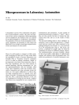
1
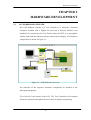
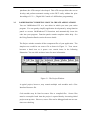
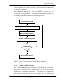
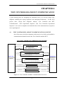
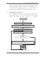
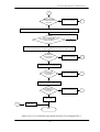
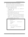
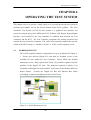
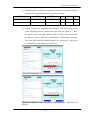
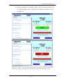
Test Controller and DUT Communication
Figure 4-1 gives a glimpse of the established means of communication
between the Test Controller and the DUT’s CPU. The principle behind the
communication make use of the fact that the Test Controller and the ETS
program residing in the DUT have access to a common shared RAM memory.
Therefore, communication using the concept of passing parameters to an
identified memory location to be extracted by another party through simple
handshaking functions was established as a means of communication. Five
common memory locations in the shared RAM, namely, “Command”,
“Acknowledgement”, “RAM Test Result”, “Flash ID” and “ DIP Switch +
TP2”, were identified to serve the communication functions required (Refer to
Figure 4-1).
In order to ensure the success of this communication, the
requirements for the Test Controller’s to perform read and write functions from
and to the shared RAM location of the DUT respectively, must first be
achieved. These read and write functions were established in conjunction with
the DUT read and write cycles specifications requirements as spelt out by
Project Monza Hardware Interface Specification document [8].
To illustrate this communication features, assume that the Test Controller
wants to know the current DIP Switch setting. It is important to note that the
Test Controller has no direct access to read the DIP Switch setting. Therefore,
it needs the service of the DUT’s CPU using the ETS program to pass this
information to the “DIP Switch + TP2” memory location. This process will
start with the Test Controller indicating its intention to know the current DIP
Switch position by setting the “Command” memory location with ‘0x0011’
data, signifying ‘DIP Switch Reading’ request.
The ETS program that
continuously polls the “Command” memory location will notice this request.
Upon receiving this command successfully, the ETS places a ‘0x0001’ data on
the “Acknowledgement” memory location to reiterate a ‘Command
Acknowledgement by ETS’ to the Test Controller. In parallel, the ETS will
also read the current DIP Switch position and place the read result onto the
“DIP Switch + TP2” memory location.
Upon reading the ‘Command
Acknowledgement by ETS’ from the DUT, the Test Controller will proceed to
read the “DIP Switch + TP2” memory location for the current DIP Switch
18