1
ÎÎ
GE Fanuc Automation
Programmable Control Products
t
Logicmaster 90-30 and Logicmaster 90-70
TCP/IP-Ethernet
User’s Manual Supplement
GFK-1029B
April 1996
GFL–002
Warnings, Cautions, and Notes
as Used in this Publication
Warning
Warning notices are used in this publication to emphasize that
hazardous voltages, currents, temperatures, or other conditions that
could cause personal injury exist in this equipment or may be
associated with its use.
In situations where inattention could cause either personal injury or
damage to equipment, a Warning notice is used.
Caution
Caution notices are used where equipment might be damaged if care is
not taken.
Note
Notes merely call attention to information that is especially significant to
understanding and operating the equipment.
This document is based on information available at the time of its publication. While
efforts have been made to be accurate, the information contained herein does not
purport to cover all details or variations in hardware or software, nor to provide for
every possible contingency in connection with installation, operation, or maintenance.
Features may be described herein which are not present in all hardware and software
systems. GE Fanuc Automation assumes no obligation of notice to holders of this
document with respect to changes subsequently made.
GE Fanuc Automation makes no representation or warranty, expressed, implied, or
statutory with respect to, and assumes no responsibility for the accuracy, completeness,
sufficiency, or usefulness of the information contained herein. No warranties of
merchantability or fitness for purpose shall apply.
The following are trademarks of GE Fanuc Automation North America, Inc.
Alarm Master
CIMPLICITY
CIMPLICITY PowerTRAC
CIMPLICITY 90–ADS
CIMSTAR
Field Control
GEnet
Genius
Genius PowerTRAC
Helpmate
Logicmaster
Modelmaster
PowerMotion
ProLoop
PROMACRO
Series Five
Series 90
Copyright 1996 GE Fanuc Automation North America, Inc.
All Rights Reserved
Series One
Series Six
Series Three
VuMaster
Workmaster
Preface
Revisions to This Manual
This manual has been revised to include the Logicmaster 90-30 TCP/IP-Ethernet
software package. Because the TCP/IP-Ethernet versions of Logicmaster 90-30 and
Logicmaster 90-70 software are similar in operation, the Ethernet-specific documentation
for both products has been combined in this manual.
Logicmaster 90-30 TCP/IP Ethernet includes Serial Line Internet Protocol (SLIP). This
new feature allows a Logicmaster 90-30 programmer to communicate with 90-30 PLCs
on an Ethernet network through a dial-up phone line.
Content of This Manual
t
This manual describes the TCP/IP versions of Logicmaster 90-30 and Logicmaster 90-70
software (Logicmaster 90-30 TCP/IP-Ethernet and Logicmaster 90-70 TCP/IP-Ethernet).
The software runs on a Workmaster computer or IBM PC compatible computer
connected directly to the Ethernet network. This provides a central location from which
to program Series 90 -30 and Series 90-70 PLCs attached to the Ethernet network.
These software packages include all the features of the standard Logicmaster 90
software. In addition, the software includes Network Utilities, which facilitate the
start-up of a system and provide troubleshooting data for the Logicmaster 90 station.
t
The manual is organized as follows:
GFK-1029B
Chapter 1.
Introduction: This chapter describes the product in general and types of
users of the product. A quick guide to the manual is also provided.
Chapter 2.
Installing and Starting Up the Software: This chapter describes how to
install and start up the software on a Workmaster or IBM PC compatible
computer.
Chapter 3.
Establishing Communications with PLC Stations: This chapter explains
the task of establishing communications with a Series 90-30 or a Series
90-70 PLC Station to perform Logicmaster functions.
Chapter 4.
Network Utilities: This chapter describes the functions of the Network
Utilities. This chapter is primarily for personnel responsible for the
operation of the network.
Appendix A.
Quick Start Install Program (Series 90-70 Only): This appendix describes
the Quick Start Install program that can be used to install Logicmaster
90-70 software, Beame & Whiteside TCP/IP software, and GSM software
on the same computer. (This is for the initial installation of these products
only, not upgrades.)
iii
Preface
Related Publications
t
Logicmastert 90-30/20/Micro ProgrammableControllersReference Manual, GFK-0467
Logicmastert 90-70 Programming Software User’s Manual, GFK-0263
Logicmastert 90-70 Programming Software Reference Manual, GFK-0265
Logicmaster 90-30/20/Micro Programming Software User’s Manual, GFK-0466
TCP/IP Ethernet Communications for the Series 90-70 PLC User’s Manual, GFK-1004
TCP/IP Ethernet Communications for the Series 90-30 PLC User’s Manual, GFK-1084
TCP/IP Ethernet Communications for the Series 90-30 PLC Station Manager’s Manual,
GFK-1186
Installation Guide for Beame & Whiteside Software, GFK-1273
At GE Fanuc Automation, we strive to produce quality technical documentation. After
you have used this manual, please take a few moments to complete and return the
Reader ’s Comment Card located on the next page.
Libby Allen
Senior Technical Writer
iv
Logicmaster 90-30 and Logicmaster 90-70 TCP/IP-Ethernet User’s Manual Supplement–April 1996
GFK-1029B
Contents
Chapter 1
Chapter 2
Chapter 3
Chapter 4
Appendix A
GFK-1029B
Introduction . . . . . . . . . . . . . . . . . . . . . . . . . . . . . . . . . . . . . . . . . . . . . . .
1-1
The Logicmaster 90-30/90-70 TCP/IP Network . . . . . . . . . . . . . . . . . . . . . . . .
1-2
Contents of the Software Packages . . . . . . . . . . . . . . . . . . . . . . . . . . . . . . . . . .
1-3
Users of the Software Package . . . . . . . . . . . . . . . . . . . . . . . . . . . . . . . . . . . . . .
1-4
Quick Guide to this Manual . . . . . . . . . . . . . . . . . . . . . . . . . . . . . . . . . . . . . . . .
1-4
Installing and Starting the Software . . . . . . . . . . . . . . . . . . . . . . . . . .
2-1
Computer Requirements for Running the Software . . . . . . . . . . . . . . . . . . .
2-2
Configuring the TCP/IP Ethernet Interfaces . . . . . . . . . . . . . . . . . . . . . . . . . .
2-2
Series 90-30 . . . . . . . . . . . . . . . . . . . . . . . . . . . . . . . . . . . . . . . . . . . . . . . . . . .
2-2
Series 90-70 . . . . . . . . . . . . . . . . . . . . . . . . . . . . . . . . . . . . . . . . . . . . . . . . . . .
2-2
Installing Logicmaster 90-30 or 90-70 for TCP/IP Ethernet . . . . . . . . . . . . . .
2-3
Preliminary Steps . . . . . . . . . . . . . . . . . . . . . . . . . . . . . . . . . . . . . . . . . . . . . .
2-4
Installing Beame & Whiteside Software for Direct Ethernet Connection
2-5
Installing Beame & Whiteside Software for SLIP Communications . . . .
2-7
Installing the Logicmaster 90 TCP/IP Ethernet Software . . . . . . . . . . . . . . . .
2-9
Modifying CONFIG.SYS, AUTOEXEC.BAT, and PROTOCOL.INI . . . . . . . .
2-10
Starting the Logicmaster 90 Software . . . . . . . . . . . . . . . . . . . . . . . . . . . . . . . .
2-12
Establishing Communications with PLC Stations . . . . . . . . . . . . . .
3-1
Identifying PLCs on the Network . . . . . . . . . . . . . . . . . . . . . . . . . . . . . . . . . . .
3-1
Accessing the PLC List Screen . . . . . . . . . . . . . . . . . . . . . . . . . . . . . . . . . . .
3-1
Adding an Entry to the PLC List . . . . . . . . . . . . . . . . . . . . . . . . . . . . . . . . .
3-4
Establishing Communications . . . . . . . . . . . . . . . . . . . . . . . . . . . . . . . . . . . . . .
3-6
Storing Programs in Run Mode (Run-Mode-Store) . . . . . . . . . . . . . . . . . . . . .
3-7
Network Utilities . . . . . . . . . . . . . . . . . . . . . . . . . . . . . . . . . . . . . . . . . .
4-1
Selecting the Network Utilities . . . . . . . . . . . . . . . . . . . . . . . . . . . . . . . . . . . . .
4-1
Network Utilities Operation . . . . . . . . . . . . . . . . . . . . . . . . . . . . . . . . . . . . . . . .
4-4
PLC List Screen . . . . . . . . . . . . . . . . . . . . . . . . . . . . . . . . . . . . . . . . . . . . . . . . . . .
4-5
Set Password Screen . . . . . . . . . . . . . . . . . . . . . . . . . . . . . . . . . . . . . . . . . . . . . .
4-6
Quick Start Install Program (Series 90-70 Only) . . . . . . . . . . . . . . . .
A-1
What Does the Quick Start Program Install? . . . . . . . . . . . . . . . . . . . . . . . . . .
A-1
Installation Diskettes . . . . . . . . . . . . . . . . . . . . . . . . . . . . . . . . . . . . . . . . . . . . . .
A-2
Before Running the Install Program . . . . . . . . . . . . . . . . . . . . . . . . . . . . . . . . .
A-2
Worksheet . . . . . . . . . . . . . . . . . . . . . . . . . . . . . . . . . . . . . . . . . . . . . . . . . . . . . .
A-3
Running the Install Program . . . . . . . . . . . . . . . . . . . . . . . . . . . . . . . . . . . . . . .
A-5
Troubleshooting Quick Start Install Problems . . . . . . . . . . . . . . . . . . . . . . . . .
A-8
Logicmaster90-30 and Logicmaster 90-70 TCP/IP-Ethernet User’s Manual Supplement–April 1996
v
Contents
Figure 1-1. The Logicmaster 90 TCP/IP Network Using Direct Ethernet Connection . . . . . . . . . . . . .
1-3
Figure 2-1. Configuration Block Diagram for Direct Ethernet Connection . . . . . . . . . . . . . . . . . . . . . .
2-3
Figure 2-2. Configuration Block Diagram for SLIP Connection (Series 90-30 Only) . . . . . . . . . . . . . . .
2-3
Figure 2-3. Logicmaster 90 Software Main Menu . . . . . . . . . . . . . . . . . . . . . . . . . . . . . . . . . . . . . . . . . . .
2-12
Figure 2-4. Logicmaster 90 Setup File Editor Menu . . . . . . . . . . . . . . . . . . . . . . . . . . . . . . . . . . . . . . . . . .
2-12
Figure 2-5. Logicmaster 90 PLC Communications Options Menu . . . . . . . . . . . . . . . . . . . . . . . . . . . . .
2-13
Figure 3-1. Logicmaster 90 Main Menu . . . . . . . . . . . . . . . . . . . . . . . . . . . . . . . . . . . . . . . . . . . . . . . . . . . .
3-1
Figure 3-2. Logicmaster 90 Utilities Menu . . . . . . . . . . . . . . . . . . . . . . . . . . . . . . . . . . . . . . . . . . . . . . . . . .
3-2
Figure 3-3. Password Screen . . . . . . . . . . . . . . . . . . . . . . . . . . . . . . . . . . . . . . . . . . . . . . . . . . . . . . . . . . . . .
3-2
Figure 3-4. Network Utilities Menu . . . . . . . . . . . . . . . . . . . . . . . . . . . . . . . . . . . . . . . . . . . . . . . . . . . . . . .
3-3
Figure 3-5. PLC List Screen . . . . . . . . . . . . . . . . . . . . . . . . . . . . . . . . . . . . . . . . . . . . . . . . . . . . . . . . . . . . . .
3-4
Figure 3-6. Use of “ID:” Field to Identify Connected PLC . . . . . . . . . . . . . . . . . . . . . . . . . . . . . . . . . . . . .
3-5
Figure 3-7. Programmer Setup Menu . . . . . . . . . . . . . . . . . . . . . . . . . . . . . . . . . . . . . . . . . . . . . . . . . . . . .
3-6
Figure 3-8. Select PLC Connection Screen . . . . . . . . . . . . . . . . . . . . . . . . . . . . . . . . . . . . . . . . . . . . . . . . .
3-7
Figure 4-1. Logicmaster 90 Utilities Menu . . . . . . . . . . . . . . . . . . . . . . . . . . . . . . . . . . . . . . . . . . . . . . . . . .
4-1
Figure 4-2. The Password Screen . . . . . . . . . . . . . . . . . . . . . . . . . . . . . . . . . . . . . . . . . . . . . . . . . . . . . . . . .
4-2
Figure 4-3. Network Utilities Menu . . . . . . . . . . . . . . . . . . . . . . . . . . . . . . . . . . . . . . . . . . . . . . . . . . . . . . .
4-3
Figure 4-4. PLC List Screen . . . . . . . . . . . . . . . . . . . . . . . . . . . . . . . . . . . . . . . . . . . . . . . . . . . . . . . . . . . . . .
4-5
Figure 4-5. Set Password Screen . . . . . . . . . . . . . . . . . . . . . . . . . . . . . . . . . . . . . . . . . . . . . . . . . . . . . . . . . .
4-6
GFK-1029B
Logicmaster90-30 and Logicmaster 90-70 TCP/IP-Ethernet User’s Manual Supplement–April 1996
vi
Contents
Table 1-1. Logicmaster 90 Prerequisites for PLCs . . . . . . . . . . . . . . . . . . . . . . . . . . . . . . . . . . . . . . . . . . . .
1-2
Table 1-2. Software Package Contents . . . . . . . . . . . . . . . . . . . . . . . . . . . . . . . . . . . . . . . . . . . . . . . . . . . . .
1-3
Table 1-3. Quick Guide to this Manual . . . . . . . . . . . . . . . . . . . . . . . . . . . . . . . . . . . . . . . . . . . . . . . . . . . . .
1-4
Table 4-1. Use of the Function Keys in the Network Utilities . . . . . . . . . . . . . . . . . . . . . . . . . . . . . . . . . .
4-4
Table 4-2. Use of the Editing Keys in the Network Utilities . . . . . . . . . . . . . . . . . . . . . . . . . . . . . . . . . . .
4-4
Table A-1. Network Adapter Cards Supported . . . . . . . . . . . . . . . . . . . . . . . . . . . . . . . . . . . . . . . . . . . . . .
A-4
GFK-1029B
Logicmaster90-30 and Logicmaster 90-70 TCP/IP-Ethernet User’s Manual Supplement–April 1996
vii
restart lowapp ARestart oddapp: ARestarts for autonumbers that do not restart in
each chapter. figure bi level 1, reset table_big level 1, reset chap_big level 1, reset1
Lowapp Alwbox restart evenap:A1app_big level 1, resetA figure_ap level 1, reset
table_ap level 1, reset figure level 1, reset table level 1, reset these restarts
oddbox reset: 1evenbox reset: 1must be in the header frame of chapter 1. a:ebx, l 1
resetA a:obx:l 1, resetA a:bigbx level 1 resetA a:ftr level 1 resetA c:ebx, l 1 reset1
c:obx:l 1, reset1 c:bigbx level 1 reset1 c:ftr level 1 reset1 Reminders for
autonumbers that need to be restarted manually (first instance will always be 4)
let_in level 1: A. B. C. letter level 1:A.B.C. num level 1: 1. 2. 3. num_in level 1: 1. 2.
3. rom_in level 1: I. II. III. roman level 1: I. II. III. steps level 1: 1. 2. 3.
Chapter
1 Introduction
1
t
This manual describes the TCP/IP-Ethernet versions of Logicmaster 90-30 and
Logicmaster 90-70 software. These software packages provide a central location from
which to program PLCs attached to the Ethernet network via TCP/IP Ethernet
Interfaces.*
Software Package
Catalog Number
Logicmaster90-30TCP/IP-Ethernet
3.5” Disks; documentation on CD-ROM
IC641SWC313
3.5” Disks; paper documentation
IC641SWM313
Logicmaster90-70TCP/IP-Ethernet
3.5” Disks; documentation on CD-ROM
IC641SWC713
3.5” Disks; paper documentation
IC641SWM713
TheTCP/IP-Ethernet version of the Logicmaster software package includes all the
features of the respective standard Logicmaster software package. In addition, it
includes a set of Network Utilities that facilitate PLC address list management and
Beame & Whiteside TCP/IP software.
The Logicmaster 90-70 TCP/IP-Ethernet package includes GEnet System Manager (GSM)
software (IC651EN5042), which is required to download configuration files and
communications software to the TCP/IP Ethernet Interfaces (IC697CMM741) located in
each Series 90-70 PLC on the network. The GSM can be installed on the same PC as that
used for Logicmaster 90-30/90-70 software, or on a separate PC. GSM is not needed for
Series 90-30 TCP/IP Ethernet interfaces.
Figure 1-1 shows the major components of an Ethernet network designed to program
and configure Series 90-30 or 90-70 PLCs using Logicmaster 90-30 TCP/IP-Ethernet or
Logicmaster 90-30 TCP/IP-Ethernet software. The configuration shown in Figure 1-1 uses
a Direct Ethernet connection, in which the PC running Logicmaster 90 software
incorporates an Ethernet card and is connected directly to the same network as the
PLCs.
The Logicmaster 90-30 TCP/IP-Ethernet package also supports Serial Line Internet
Protocol (SLIP), as an alternative to the Direct Ethernet connection. Using SLIP, a remote
PC, running Logicmaster 90 software, connects to a modem via a COM port. The PC
communicates via telephone line with a SLIP server that is connected to the network
with the PLCs.
* The TCP/IP protocols and the software that supports them are distinct from those used to
perform similar functions via OSI-Ethernet protocols.
GFK-1029B
1-1
1
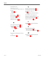
The Logicmaster 90-30/90-70 TCP/IP Network
For the software package to operate, there must be a network of Series 90-30 or Series
90-70 PLCs and a personal computer for running the Logicmaster 90-30 or Logicmaster
90-70TCP/IP-Ethernet software. General network requirements are summarized below,
with requirements for software and firmware listed in Table 1-1.
H
!! H
! " ! H
H
Each station consists of a Series 90-30 or Series 90-70 PLC with
installed Ethernet Interface.
Series 90-70 only. This consists of a personal
computer attached to the network with the GSM software installed. The GSM is
required to configure the TCP/IP Interfaces installed in the Series 90-70 PLCs before
the Logicmaster package can communicate with them. Refer to GFK-1004, TCP/IP
Communications for the Series 90-70 User’s Manual, for information about GSM
operation.
! # ! # !! !! This consists
of Logicmaster 90-30 or 90-70 TCP/IP-Ethernet software installed in a Workmaster
computer or PC-compatible computer that has an Ethernet card (for Direct Ethernet
connections) or a COM port and modem (for SLIP connection).
! The cable plant should be designed by an experienced Ethernet
installer. This consists of the cabling and physical equipment necessary to connect
the devices listed above to a common network. SLIP connection further assumes the
availability of a SLIP server on the network to which the PLCs are connected.
Table 1-1. Logicmaster 90 Prerequisites for PLCs
Installation
1-2
PLC CPU Firmware
Ethernet Interface Software
Logicmaster90-30TCP/IP
Series 90-30 PLC Rev. 6.5 or later
Ethernet Interface
TCP/IPsoftwareRev. 1.10 or later
Logicmaster90-70TCP/IP
Series 90-70 PLC Rev. 4.12 or later
Ethernet Interface PROM Rev. 1.15 or later
TCP/IPsoftwareRev. 1.28 or later
Logicmaster 90-30 and Logicmaster 90-70 TCP/IP-Ethernet User’s Manual Supplement–April 1996
GFK-1029B
1
ÎÎÎÎ
ÎÎÎÎ
Transceiver
Ethernet Card
ÎÎÎÎÎ ÎÎÎÎÎ
ÎÎÎÎÎ ÎÎÎÎÎ
ÎÎ
Î
ÎÎ
ÎÎ
Î
Î
ÎÎ
Î
ÎÎ
Î
ÎÎ
ÎÎ
Î
ÎÎ
ÎÎ
Î
Î
ÎÎ
Î
ÎÎ
Î
ÎÎ
Î
Î
Î
Î
ÎÎ
Î
ÎÎ
ÎÎ
Î
ÎÎ
Î
Î
ÎÎ
ÎÎÎ
Î
ÎÎ
Î
ÎÎ
ÎÎ
Î
ÎÎ
Î
ÎÎ
Î
ÎÎ
ÎÎÎÎ
ÎÎ
ÎÎ
ÎÎ
ÎÎÎ
ÎÎ
Î
Î
Î
Ethernet Network
Transceiver
TCP/IP Ethernet Interface
C
P
U
C
P
U
PLC Station
(Series 90-70)
Logicmaster 90-30 or
Logicmaster 90-70
TCP/IP-Ethernet Station
Transceiver
PLC Station
(Series 90-30)
Logicmaster 90-30 and/or Logicmaster 90-70
TCP/IP Ethernet software is installed on a PC compatible
Logicmaster TCP/IP-Ethernet station.
GSM software (90-70 version only) is used to download
configuration files and communications software to
Ethernet Interfaces (IC697CMM741) located in
each 90-70 PLC on the network.
Figure 1-1. The Logicmaster 90 TCP/IP Network Using Direct Ethernet Connection
Contents of the Software Packages
Table 1-2. Software Package Contents
Package
Logicmaster 90-30
TCP/IP-Ethernet
(IC641SWC313/
IC641SWM313)
5 – Beame & Whiteside diskettes (3.5-inch)
2 – Logicmaster diskettes (3.5-inch)
1 – Logicmaster 90-30/90-70 TCP/IP-Ethernet Software User’s Manual Supplement,
GFK-1029 (this manual)
1 – Installation Guide for Beame & Whiteside Software, GFK-1273
1 – Important Product Information for Logicmaster 90-30 TCP/IP-Ethernet
Software, GFK-1323
1 – Documentation library, CD-ROM (for IC641SWC313 package)
1 – Documentation library, paper (for IC641SWM313 package)
Logicmaster 90-70
TCP/IP-Ethernet
(IC641SWC713/
IC641SWM713)
1 – Quick Start Install Diskette (3.5-inch)
1 – GSM diskette labeled Series 90-70 TCP/IP Ethernet SW, IC651ENS042
(3.5-inch)
5 – Beame & Whiteside diskettes (3.5-inch)
2 – Logicmaster diskettes (3.5-inch)
1 – Logicmaster 90-30/90-70 TCP/IP-Ethernet Software User’s Manual Supplement,
GFK-1029 (this manual)
1 – Installation Guide for Beame & Whiteside Software, GFK-1273
1 – Important Product Information for Logicmaster 90-70 TCP/IP-Ethernet
Software, GFK-1030
1 – Documentation library, CD-ROM (for IC641SWC713 package)
1 – Documentation library, paper (for IC641SWM713 package)
t
GFK-1029B
t
Contents
Beame & Whiteside is a trademark of Beame & Whiteside Software, Inc.
Chapter 1 Introduction
1-3
1
Users of the Software Package
This manual provides information for two groups of users of the Logicmaster 90-30 or
90-70TCP/IP-Ethernet Software package:
H
H
PLC Logic Programming Personnel
Network Personnel
PLC Logic Programming Personnel use the Logicmaster 90 TCP/IP-Ethernet software
package to program and perform CPU and I/O configuration for Series 90-30 or Series
90-70 PLCs. These tasks involve establishing connections from Logicmaster to various
PLCs on the network. This group is usually not involved in setting up and maintaining
the network.
Network Personnel will use the Network Utilities to build the list of PLCs.
Quick Guide to this Manual
This manual is a supplement to the user’s and reference manuals for Logicmaster 90-30
and Logicmaster 90-70 software – it documents the aspects of Logicmaster software that
are unique to the TCP/IP versions. Table 1-3 identifies the tasks unique to the
TCP/IP-Ethernet versions of Logicmaster 90-30 and Logicmaster 90-70 software and
where to find them in this manual. To use the software to program logic in the PLC,
consult the appropriate user’s and reference manuals listed in the “Preface.”
Table 1-3. Quick Guide to this Manual
ÁÁÁÁÁÁÁÁÁÁÁÁÁ
ÁÁÁÁÁÁÁÁÁÁÁÁÁÁÁ
ÁÁÁÁÁÁÁÁÁÁÁÁÁ
ÁÁÁÁÁÁÁÁÁÁÁÁÁÁÁ
ÁÁÁÁÁÁÁÁÁÁÁÁÁ
ÁÁÁÁÁÁÁÁÁÁÁÁÁÁÁ
ÁÁÁÁÁÁÁÁÁÁÁÁÁ
ÁÁÁÁÁÁÁÁÁÁÁÁÁÁÁ
ÁÁÁÁÁÁÁÁÁÁÁÁÁ
ÁÁÁÁÁÁÁÁÁÁÁÁÁÁÁ
ÁÁÁÁÁÁÁÁÁÁÁÁÁ
ÁÁÁÁÁÁÁÁÁÁÁÁÁÁÁ
ÁÁÁÁÁÁÁÁÁÁÁÁÁ
ÁÁÁÁÁÁÁÁÁÁÁÁÁÁÁ
Task
Installingand Starting-Up the Software
Establishing a Connection to a PLC for
PLC Program and Configuration Download
Building PLC address lists
1-4
Where to look in this Manual
Chapter 2. Installing and Starting-Up the Software
Appendix A. Quick Start Install Program
(90-70 only)
Chapter 3. Establishing Communications with
PLC Stations
Chapter 4. NetworkUtilities
Logicmaster 90-30 and Logicmaster 90-70 TCP/IP-Ethernet User’s Manual Supplement–April 1996
GFK-1029B
2%#3).- +%5%+ &)'41% ") +%5%+ 3!"+% ")' +%5%+ ()2 #(!/3%1 $%2#1)"%2 (.6 3. )-23!++ 3(% 83(%1-%3 5%12).-2 .& .')#,!23%1 8
!-$ .')#,!23%1 8 2.&36!1% .- ! /%12.-!+ #.,/43%1
(% 3./)#2 #.5%1%$ )- 3()2 #(!/3%1 !1%
.,/43%1 1%04)1%,%-32 &.1 14--)-' 3(% 2.&36!1%
.-&)'41)-' 3(% 3(%1-%3 -3%1&!#%2
-23!++)-' 3(% %!,% ()3%2)$% 8.--%#3 1.$4#3
1%+),)-!17 3%/2
-23!++)-' 3(% %!,% ()3%2)$% .&36!1% &.1 )1%#3 3(%1-%3 .--%#3).-
-23!++)-' 3(% %!,% ()3%2)$% .&36!1% &.1 .,,4-)#!3).-2
-23!++)-' 3(% .')#,!23%1 83(%1-%3 .&36!1%
.$)&7)-' !-$ 3!13)-' 3(% 2.&36!1%
%!,% ()3%2)$% )2 ! 31!$%,!1* .& %!,% ()3%2)$% .&36!1% -#
To install and run Logicmaster 90Ć30 TCP/IP or Logicmaster 90Ć70 TCP/IP software, the
computer must meet the following requirements.
DOS Version 5.0 or later
80386, 80486 or Pentium computer
8.5 Megabytes of available space on hard disk for Logicmaster and Beame &
WhitesideĆConnect TCP products
2 Megabytes of RAM
600 Kilobytes (614,400 bytes) of Free Conventional Memory. To determine this value
for your personal computer, execute the DOS command after completely
installing the software package and rebooting.
Diagnostics disk from Ethernet interface vendor (Direct Ethernet Connection only)
Refer to GFKĆ1084, TCP/IP Ethernet Communications User's Manual for configuration
information.
&# !" " !" ' " " !"$ " !" " " % # " " !"" The
Quick Start Installation Program installs Logicmaster 90Ć70 software,
Beame & Whiteside software for direct Ethernet communication, and
the GSM software.
The GSM is used to configure the TCP/IP Ethernet Interfaces installed in the Series 90Ć70
PLCs on the network. This must be done before Logicmaster 90Ć70 software can
communicate with the PLCs. The operation of the the GSM is described in GFKĆ1004,
TCP/IP Ethernet Communications User's Manual. Refer to appendix A of this manual
(GFKĆ1029) if you are installing the GSM software on the same PC as Logicmaster 90Ć70
software. Refer to GFKĆ1004 if you are installing the GSM software on a separate PC.
If you are updating Logicmaster 90Ć70 Software or the Beame &
Whiteside software, refer to the instructions in this chapter. If you are
updating the GSM software, refer to GFKĆ1004 for instructions.
2Ć2
Logicmaster 90Ć30 and Logicmaster 90Ć70 TCP/IPĆEthernet User's Manual Supplement-April 1996
GFKĆ1029B
Installing Logicmaster 90Ć30 or 90Ć70 for TCP/IP Ethernet
)! &*"% ! &$ & %% $ ( ! &% &$ &(% $#'$% %& &
%&&! "$!'$ !$ & &% %!&)$
Direct Ethernet connection $'
!$"!$&% &$ & $ % !
& %
!%&$ %!&)$
& $&* &! & % &)!$ %
SLIP $!& $' !%&$ %!&)$ '%% "!$& &!
! & &! ! !' &% ( &"! )& %$($ && % ! & &! & &)!$ )& & %
Logicmaster 90-30
or 90-70 Ethernet
Series 90-30 or
90-70 PLC
with Ethernet
Interface
Ethernet card
Ethernet
Series 90-30 or
90-70 PLC
with Ethernet
Interface
Series 90-30 or
90-70 PLC
with Ethernet
Interface
Figure 2Ć1. Configuration Block Diagram for Direct Ethernet Connection
Series 90-30 PLC
with Ethernet
Interface
Logicmaster 90-30
Ethernet
COM
Ethernet
Modem
Phone
SLIP
Server
Modem
Serial
Serial
Series 90-30 PLC
with Ethernet
Interface
Series 90-30 PLC
with Ethernet
Interface
Figure 2Ć2. Configuration Block Diagram for SLIP Connection (Series 90Ć30 Only)
GFKĆ1029B
Chapter 2 Installing and Starting the Software
2Ć3
This procedure assumes that you will be using an NDIS driver. If you are using ODI, the
procedure may vary. The following steps should be completed in order.
1.
Make a bootable floppy disk.
2.
Save your existing AUTOEXEC.BAT and CONFIG.SYS files.
3.
If you will be using Direct Ethernet connection, install the PC Ethernet adapter in
your PC.
4.
Make a copy of the Beame & Whiteside Preliminary Worksheet and fill it out. (A
partially filled out worksheet is shown in Appendix A.) You will need to determine:
IRQ Address
I/O Address
Shared memory (Yes or No - If yes, you will need the start address.)
Buffer space 10,000 for Logicmaster 90 software
Software interrupt vector
For requirements specific to SLIP, refer to page 2Ć7.
5.
If your PC Ethernet adapter has installation software with it, run the INSTALL
program.
6.
Continue with installation:
D. If you are using 90Ć70 and this is an initial installation on this PC, continue with
the Quick Start installation in Appendix A.
E. If this installation is 90Ć30 and you will use SLIP, continue on page 2Ć7.
F.
2Ć4
Otherwise, continue on page 2Ć5.
Logicmaster 90Ć30 and Logicmaster 90Ć70 TCP/IPĆEthernet User's Manual Supplement-April 1996
GFKĆ1029B
The Beame & WhitesideĆConnect TCP product comes with thorough installation instrucĆ
tions in the Installation Guide for Beame & Whiteside Software, GFKĆ1273. Some specific
areas of the process are worth noting.
1.
The Installation Guide (GFKĆ1273) contains information for two Beame & Whiteside
products: BWĆTCP and BWĆNFS. Only BWĆTCP is distributed with this product.
2.
Be sure that the system requirements given in GFKĆ1273 are met. This will assure
that the process is not terminated before completion.
3.
Fill out the Preliminary Worksheet in GFKĆ1273. A modified version of this
worksheet also appears in Appendix A of this manual. Having this information
available will make the installation process easier.
4.
When running the install program, you will be given the option of setting the Buffer
Space used by the driver. The default value is 26000. Changing this to 10000 will free
up more conventional memory, which is needed for Logicmaster 90 software to run.
When you have installed the Beame & Whiteside software in your PC, you must check
your system to determine if the required amount of Free Conventional Memory is availĆ
able. Instructions on how to read this value are given in Computer Requirements for
Running the Software" on page 2Ć2. If the requirements are not met, refer to the docuĆ
mentation for your memory manager software to find examples on how to load device
drivers into high memory. (For example, MSĆDOS EMM386 memory manager uses the
command DEVICEHIGH in place of the standard DEVICE statement to load a driver
into high memory.) We recommend loading both Beame & Whiteside drivers
(ETHDEV.SYS and TCPIP.SYS) into high memory.
Once memory requirements are met, various utilities provided by the BWĆConnect
product should be used to test the validity of the TCP/IP configuration. In particular, the
ping" utility should be used to verify that the PLCs to which you desire communication
are reachable. Further information on the use of ping" can be found in the TCP/IP EtherĆ
net Communications for the Series 90Ć70 PLC User's Manual (GFKĆ1004) and in TCP/IP EtherĆ
net Communications for the Series 90Ć30 PLC Station Manager's Manual (GFKĆ1186).
BWĆConnect is a trademark of Beame & Whiteside Software, Inc.
GFKĆ1029B
Chapter 2 Installing and Starting the Software
2Ć5
%*3 8.41 "-% ! '*+&2 2. 3)"3 3)&8 $.-3"*- 3)&
'.++.6*-( +*-&2
CONFIG.SYS
FILES=20
BUFFERS=48
DEVICE=\DOS\HIMEM.SYS
DEVICE=\DOS\EMM386.EXE RAM 1024
Notes:
)& -4,#&1 .' #4''&12 ,"8 -&&% 3. #& 1&%4$&% -.3 #&+.6 *' 3)& ,*-*,4,
,&,.18 1&04*1&,&-32 "1& -.3 ,&3
' 8.41 $.,/43&1 )"2 &7$+4%&2 "-% *-$+4%&2 .- 3)& +*-& 8.4 ,"8
-&&% 3. "%% 3)&,
AUTOEXEC.BAT
PROMPT $P$G
PATH=C:\DOS;C:\
-23"++ 3)& &",& )*3&2*%& 2.'36"1&
Notes:
&3 3)& &",& )*3&2*%& 2.'36"1& ,.%*'8 8.41 2823&, '*+&2
. -.3 %. 3)& *-%.62 *-23"++"3*.-
3"13 3)& &",& )*3&2*%& 2.'36"1& "-% $.-'*1, 3)"3 $.,,4-*$"3*.- *2
&23"#+*2)&% #&36&&- 3)& "-% 3)& )& ping $.,,"-% 2).4+% #& *224&% '1., 3)& 3. 3)& $.,/43&1 "2 6&++ "2 '1.,
3)& $.,/43&1 3. 3)& 3. *-241& 3)"3 3)& )"1%6"1& *-3&114/3 *2 /1./&1+8 2&3 *- 3)&
$.,/43&1 $.-'*(41"3*.-
.-'*1, 3)"3 8.4 $"- 24$$&22'4++8 *224& ping '1., 3)& "-% 1&$&*5& " /1./&1
1&2/.-2&
.-'*1, 3)"3 8.4 $"- 24$$&22'4++8 *224& ping '1., 3)& 3. 3)& "-% 1&$&*5&
" /1./&1 1&2/.-2&
)& -&73 23&/ *2 3. *-23"++ 3)& .(*$,"23&1 2.'36"1& 2&& /"(& 9
Note: &3 .(*$,"23&1 ,.%*'8 8.41 2823&, '*+&2
2Ć6
Logicmaster 90Ć30 and Logicmaster 90Ć70 TCP/IPĆEthernet User's Manual Supplement-April 1996
GFKĆ1029B
SLIP allows a Logicmaster 90Ć30 programmer to communicate to 90Ć30 PLCs on an
Ethernet Network through a dialĆup phone line. A SLIP server (Router) is needed on the
Ethernet network and a modem is needed on the Logicmaster end.
For Logicmaster 90Ć30 Ethernet to use SLIP communications, the Beame & Whiteside
software must be configured for use with SLIP.
The Beame and Whiteside installation requirements are outlined below:
1.
2.
Required information to be determined before installing the Beame & Whiteside
software:
Network Card: SLIP
Determine what port in the PC will have the modem for SLIP communication
Hardware Interrupt: 4 for COM1; 3 for COM2.
I/O Address: 3F8 for COM1; 2F8 for COM2.
Buffer = 10,000
No Shared Memory.
The SLIP server must be configured by the Ethernet Network system
administrator to have an IP address to be used by Logicmaster 90 software. See
your network administrator to get the appropriate IP address.
The Subnetwork Mask be set to 255.255.255.255.
The Default Gateway be set to 255.255.255.255.
Start with the following CONFIG.SYS and AUTOEXEC.BAT files. (In the following
steps, the Beame & Whiteside software will automatically modify them.)
CONFIG.SYS
FILES=20
BUFFERS=48
DOS=HIGH,UMB
DEVICE=\DOS\HIMEM.SYS
DEVICE=\DOS\EMM386.EXE RAM 1024
AUTOEXEC.BAT
PROMPT $P$G
PATH=C:\DOS;\C;\
Note that you may need exclude or include statements on the EMM386 line.
3.
GFKĆ1029B
Install the Beame & Whiteside software.
Do the install for DOS (at the DOS prompt, type a:bwinstall). Do not do the
install for Windows.
Answer SLIP for COM1 or COM2 to the Choose Network Adapter prompt.
4.
Choose Packet Driver for the Selected Driver Type.
5.
Use the above information in the Network Configuration screen. Default values
should be appropriate for all fields except Hardware Interrupt, I/O address, IP
Address and Default Gateway.
Chapter 2 Installing and Starting the Software
2Ć7
6.
When the software prompts you to let it update the system files automatically,
type Y.
7.
Do not do Windows setup.
8.
Edit the AUTOEXEC.BAT and CONFIG.SYS files as follows:
The Beame & Whiteside software automatically puts the
C:\BWTCP\PACKET... line into the AUTOEXEC.BAT file. It is essential
that you add the word SLIP after 0X60 and the baud rate at the end of
the line. Enter the baud rate that your modem is set at. A baud rate of
38400 is shown in the line below as an example.
AUTOEXEC.BAT
change: C:\BWTCP\PACKET\SLIP8250.COM 0X60 0X4 0X3F8
to: C:\BWTCP\PACKET\SLIP8250.COM 0X60 SLIP 0X4 0X3F8 38400
remove: C:\BWTCP\STARTNET
remove: SET BWSTAK=C:\BWTCP
remove: SET DOMAIN=CHO.GE.COM
CONFIG.SYS
change: DEVICE=C:\BWTCP\ETHDEV.SYS
to: DEVICEHIGH=C:\BWTCP\ETHDEV.SYS
change: DEVICE=C:\BWTCP\\TCPIP.SYS 1460 2920 20
to: DEVICEHIGH=C:\BWTCP\\TCPIP.SYS 1460 2920 20
1.
In the BWTCP directory, type:
BWDIALER /C=<port#> /B=38400 <phone #>
This will start the the SLIP client running out of the COM port at the entered baud
rate. It will also dial the number <phone #>.
2.
Most SLIP Servers will then require a login and a password to complete connection
establishment. Check with your System Administrator to get details for login.
3.
Check with your System Administrator to determine what, if anything, you have to
do after login to the server to start SLIP
4.
Press ALTĆX to return to the DOS prompt on the host PC.
5.
Confirm that you can successfully issue ping from the PC and receive a proper
response.
6.
Confirm that you can successfully issue ping from the PLC to the PC and receive a
proper response.
The next step is to install the Logicmaster 90 software (see page 2Ć9).
2Ć8
Logicmaster 90Ć30 and Logicmaster 90Ć70 TCP/IPĆEthernet User's Manual Supplement-April 1996
GFKĆ1029B
The Logicmaster 90Ć30 TCP/IPĆEthernet and Logicmaster 90Ć70 TCP/IPĆEthernet
software packages are each shipped on two 3.5Ćinch, highĆdensity distribution diskettes.
The instructions below explain how to load the software package files from the
distribution diskettes onto your hard disk. The instructions assume the use of floppy
drive A, but you can also load the software from another drive.
1.
Insert distribution diskette 1 into Drive A, or another drive if desired.
2.
From the A: prompt, type.
3.
A screen appears prompting you to enter the destination hard drive for the software
package. Enter the drive letter (or use the default drive that is provided) and press
Enter.
4.
If this is the first installation of the software, a screen for registering the software
appears. This screen contains prompts for your name, company, address, and
software serial number. Fill in this information.
A:\> install
The serial number for your software is located on the back of diskette
number 1.
After you have entered the information, press Enter.
5.
A screen for confirming the registration information appears next. If the information
you entered is correct, press Enter. If it is not, press Esc to correct any information. If
you pressed Enter, the data is then written onto the master distribution disk. (Don't
write protect the master disk until after the first installation.)
6.
The Copyright screen then appears. Press Enter to continue.
7.
The AUTOEXEC.BAT and CONFIG.SYS modification screen appears next. Press Yif
you want the Install program to automatically modify these files. Press N if you
want to modify the files yourself.
8.
If you pressed Y, the Install program will create an LM90 directory on the hard drive
you specified, and immediately begin to write the Logicmaster software to it.
If you pressed N, so you could modify the AUTOEXEC.BAT and the CONFIG.SYS
files yourself, a screen will appear prompting you to make the modifications (shown
in step 10) after installing the software. A confirm prompt also appears at the bottom
of this screen which permits you to change your mind and have the Install program
modify them for you.
Press Y for automatic update or press N if you still want to modify them yourself. In
either case, the Logicmaster 90 TCP/IP files will begin installing on your hard disk at
this time.
9.
While the software is being installed, a screen will appear indicating that the install is
“WORKING”. When all the files from a diskette are installed, you will be prompted
to insert the next diskette and press Enter to proceed. Do this step for diskette 2.
10. After the Install program writes all the files to the destination drive, your software
package has been installed. If you elected to modify the AUTOEXEC.BAT and
CONFIG.SYS files yourself, do so now (see page 2Ć10).
&'/ /#!0',+ //1*#/ 4,1 .# 1/'+% + 6!,+$,.*'+% 0&#.+#0
".'2#.
$0#. 4,1 &2# '+/0))#" 0&# #*# &'0#/'"# /,$03.# +" 0&# ,%'!*/0#. /,$03.# !&#!( 0&# +" $')#/ 0, *(#
/1.# 0 '+!)1"# 0&# $,)),3'+% #+0.'#/ then reboot your computer.
&# $')#/ #),3 .# /*-)# $')#/ -.,"1!#" 3&#+ '+/0))'+% #*# &'0#/'"# /,$03.# +" ,%'!*/0#. /,$03.# ,+ 1/'+% +
0&#.)'+( +#03,.( !." #*# &'0#/'"# .#$#./ 0, 0&'/ !." 4
0&# +*# 5ELNKMC '+ +" "! %# "$ #!" " "
! " !
(# /1.# 0&# $')# &/ 0&# $,)),3'+% #+0.'#/ ## 0&# +,0# ,+ +#03,.(
!." +*#/ ,2#
Direct Ethernet Connection
SLIP
FILES = 20
BUFFERS = 48
DEVICE = \DOS\HIMEM.SYS
DEVICE = \DOS\EMM386.EXE RAM 1024
DOS = HIGH, UMB
DEVICE=C:\BWTCP\PROTMAN.DOS /I:C:\LANMAN.DOS
DEVICEHIGH=C:\BWTCP\ELNKMC.DOS
DEVICEHIGH=C:\BWTCP\NDIS\ETHDEV.SYS
DEVICEHIGH=C:\BWTCP\NDIS\TCPIP.SYS 1460 2920 20
/*#
/*#
/*#
/*#
/*#
/*#
DEVICEHIGH=C:\BWTCP\ETHDEV.SYS
DEVICEHIGH=C:\BWTCP\TCPIP.SYS
$ $0#. *('+% !&+%#/ 0, 0&#/# $')#/ 4,1. !,*-10#. 3')) +,0 .# ,,0
-.,-#.)4 ,. '$ 4,1 &2# *#*,.4 -., )#*/ .1++'+% ,%'!*/0#.
/,$03.# 4,1 3')) +##" 0, !&+%# 0&# )'+#
DEVICE=\DOS\EMM386.EXE RAM 1024
0,
DEVICE=\DOS\EMM386.EXE noems
0&#+ .# ,,0 +" 0.4 %'+
2Ć10
Logicmaster 90Ć30 and Logicmaster 90Ć70 TCP/IPĆEthernet User's Manual Supplement-April 1996
GFKĆ1029B
)$ 02/$ 1'$ %(*$ ' 0 1'$ %-**-4(,& $,1/($0
Direct Ethernet Connection
C:\BWTCP\NDIS\NETBIND
prompt $P$G
PATH=C:\DOS;C:\;Drive ID:\LM90
SET BWSTATE=C:\BWTCP
SET DOMAIN=abc.com
SET PATH=C:\BWTCP; %path%
SLIP
0
0
0
0
0
0
+$
+$
+$
+$
+$
+$
C:\BWTCP\PACKET\SLIP8250.COM 0X60 SLIP 0X4 0X3F8 38400
'$ (0 1'$ *$11$/ "-//$0.-,#(,& 1- 1'$ ' /# #(0) #/(3$ 4'$/$ 1'$ -&("+ 01$/
8
-/ -&("+ 01$/ 8 0-%14 /$ (0 (,01 **$#
'$ *(,$ !$&(,,(,& 4(1' 7 #$%(,$0 1'$ "-+. ,6 #-+ (, , +$ % 6-2
#-,1 ' 3$ "-+. ,6 #-+ (, , +$ 20$ 1'/$$ *$11$/ "-#$ %-/ 1'$ "-+. ,6 %-**-4$#
!6 7"-+ ** (, *-4$/ " 0$ 5 +.*$ abc.com
)$ 02/$ 1'$ %(*$ ' 0 1'$ %-**-4(,& $,1/($0 $$ 1'$
,-1$ -, ,$14-/) " /# , +$0 -, . &$ 8
[ProtMan]
DriverName=PROTMAN$
[ELNKMC]
DRIVERNAME = ELNKMC$
[ETHDEV]
DriverName=ETHDEV27
Bindings=ELNKMC
(&($ * &##&-!% )*') *& )*(* * &!$)*( )&*-( '"
.' LM90 * * '(&$'* % '()) * Enter ". &!$)*( $!%
$%+ !) !)'#.
#* * (!) / (&($$# &%*(&##( Shift + F3 &( * (!) /
(&($$# &%*(&##( Shift + F5
& )#* * * (%* ,()!&% & * &!$)*( )&*-( '(&($ )*') % (&$ * !% %+ )#* F9 ... Logicmaster 90 Setup Package &!$)*( *+' !# !*&( $%+ -!## !)'#.
2Ć12
Logicmaster 90Ć30 and Logicmaster 90Ć70 TCP/IPĆEthernet User's Manual Supplement-April 1996
GFKĆ1029B
.,* 0&# ,%'!*/0#. #01- ')# "'0,. *#+1 /#)#!0 F4 ... PLC
Communications Options &# $,)),3'+% *#+1 3')) # "'/-)4#"
,SLIP)
+ 0&'/ *#+1 -.#// 0&# Tab (#4 0, /#)#!0 #'0&#. 0&# 0&#.+#0 ,-0',+ ,. 0&# ,-0',+ /# 0&#.+#0 '$ 4,1 '+/0))#" #*# &'0#/'"# /,$03.# $,. '.#!0
0&#.+#0 !,++#!0',+ /# '$ 4,1 '+/0))#" #*# &'0#/'"# /,$03.# $,.
!,**1+'!0',+/ $.,* .#*,0# /'0# &# "#$1)0 !&,'!# '/ #.') ,.0
.#// Esc 0, .#01.+ 0, 0&# #01- ')# "'0,. *#+1 +" 0&#+ -.#// F10 0, /2# 0&#
/#01- $')# &# $,)),3'+% *#//%#/ 3')) # "'/-)4#"
Setup file saved successfully as C:\lm90\lm90.dat
<<Press any key to exit>>
GFKĆ1029B
, .#01.+ 0, 0&# *'+ *#+1 -.#// Esc, Esc
, !.#0# )'/0 -.#// F7 ,%'!*/0#. 0')'0'#/ +" 0&#+ -.#// F1 #03,.(
0')'04
+0#. -//3,." "#$1)0 '/ netutil
#)#!0 0&# 0, !,**1+'!0# 0, ## -%# 5
Chapter 2 Installing and Starting the Software
2Ć13
Establishing Communications with PLC
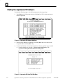
'($# !*! )& !*! (! !*! ' %(& ,%!#' ( (' $ '(!'# $"")#($#' +( &' . $&
&' . (($# ($ %&$&" $"'(& )#($#' ($%' ')'' #
(' %(& &
#(-# ' $# ( (+$&
'(!'#$"")#($#'
($&# &$&"'
$ # -$) ")'( #(- ( ' $# ( (&#( #(+$& +( + $"'(&
"- $"")#(# +$ '%&( !'(' & "#(# $# $& &' . ' #
$# $& &' . ' !'(' & )!( - #(&# &''# #$&"($# # (
'( &# + ' %&( $ ( (+$& (!(' !(# (+# ( (+$ !'(' '
$"%!' # ( $"'(& # #) ' '$+# # )&.
$ '' ( '( &# $!!$+ ( '(%' !$+
&'( '' ( $"'(& # #) ' '$+# !$+ $$' . $& .
- %&''# $& Figure 3Ć1. Logicmaster 90 Main Menu
F7... Logicmaster 90 Utilities Figure 3Ć2. Logicmaster 90 Utilities Menu
3Ć2
F1 ... Network Utility Logicmaster 90Ć30 and Logicmaster 90Ć70 TCP/IPĆEthernet User's Manual Supplement-April 1996
GFKĆ1029B
GFKĆ1029B
Chapter 3 Establishing Communications with Series 90Ć30/90Ć70 PLC Stations
3Ć3
4.
Enter the password and press Enter. (The default password is netutil). The Network
Utilities Menu will appear.
You can change the password in the F7 ... Set Password function in the
Network Utilities screen.
If you have TCP Version 0.01 on the screen below, you should replace
the NETUTILT.EXE file in the LM90 directory with a newer version of
the file from the GE Fanuc bulletin board - 804Ć978Ć5458.
3Ć4
Logicmaster 90Ć30 and Logicmaster 90Ć70 TCP/IPĆEthernet User's Manual Supplement-April 1996
GFKĆ1029B
5.
From the Network Utilities Menu, select F1... PLC List.
Figure 3Ć5. PLC List Screen
The MAC address, PLC ID and IP Address fields in the PLC List screen will be blank
initially. In the screen above, however, these fields contain the information for a sample
PLC list.
Adding an Entry to the PLC List
To add entries to the list, press F3 (add). This will open an edit field in which you can
input the MAC Address of the board to which you desire communications. After typing
in the address, press Enter to add the entry to the list. Use the arrow keys to move the
cursor to the IP Address Field for this MAC Address and enter the appropriate
information. You must enter the IP address of the desired PLC. The MAC address is also
referred to as the board address, and is used in the Select PLC Connection screen.
See the Series 90Ć70 TCP/IP Ethernet Communications User's Manual, GFKĆ1004 or Series
90Ć30 TCP/IP Ethernet Communications User's Manual, GFKĆ1084 for additional
information on MAC and IP addresses.
Assigning PLC IDs
After executing the Add function, the PLC List contains only MAC/IP addresses for the
PLCs. You can locally assign a PLC ID to the PLC to make it easier to use the list to
establish communications with PLCs. See Recommendations for Assigning PLC IDs"
below.
This PLC ID is local to the personal computer running the Logicmaster 90 TCP/IP
software. The PLC ID can be up to 8 characters long and can include any printable
character.
To assign a PLC ID, move the cursor to the left hand field of the line containing the
desired IP address, and type the PLC ID. Be sure to save the MAC/IP addresses and PLC
IDs by pressing F2 (save).
GFKĆ1029B
Chapter 3 Establishing Communications with Series 90Ć30/90Ć70 PLC Stations
3Ć5
3
Recommendation for Assigning PLC IDs
The PLC ID is local to the personal computer running the Logicmaster 90 software and is
not displayed on any Logicmaster 90 screen except for the Select PLC Connection screen
(described later in this chapter). For this reason, we strongly recommend that you set the
PLC ID equal to the SNP ID of the PLC.
Only by following our recommendation for assigning PLC IDs will you be able to tell
which PLC you are connected to in other parts of the Logicmaster 90 programming or
configuration packages, simply by viewing the “ID:” field that appears in the status lines.
A screen illustrating the use of this field is shown in Figure 3Ć6.
The SNP ID is set in the PLC, using the Logicmaster 90 Configurator software. To set the
SNP ID, press in the Logicmaster 90 main menu, then press (CPU Configuration)
in the Configuration Software menu. For additional instructions on setting the SNP ID,
refer to the appropriate user's manual: GFK-0466, Logicmaster 90-20/30/Micro
Programming Software User’s Manual or GFK-0263, Logicmaster 90-70 Programming Software
User’s Manual.
The ID: field shows
the connected PLC’s
SNP ID.
Figure 3Ć6. Use of “ID:” Field to Identify Connected PLC
3Ć6
Logicmaster 90Ć30 and Logicmaster 90Ć70 TCP/IPĆEthernet User's Manual Supplement-April 1996
GFKĆ1029B
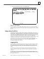
EstablishingCommunications
& "!!&"! %$! % '% &" %& & +"' )% &" "
'!&
)& % %$! %#+% & % %& " % ) )% $& % *#! ! &
#$("'% %&"! ! & %& % !& + &% "$ $%% ! % ! %%!
"' + ""% $"
&" & !%&$'&"!% ")
&% %& "$ !&$ &% ! & “& ” $
To Establish Communications:
" &" & & "!!&"! %$! " " &% $%& !&$ & $"$
$
! $! ! &! #$%% F7 ... Programmer Mode and Setup &" %%
& $"$
$ &'# !' % %")! ")
Figure 3Ć7. Programmer Setup Menu
GFKĆ1029B
Chapter 3 Establishing Communications with Series 90Ć30/90Ć70 PLC Stations
3Ć7
Then press F3... Select PLC Connection, to access the Select PLC Connection screen.
Figure 3Ć8. Select PLC Connection Screen
2.
3.
You can identify the PLC to which you want to connect in two ways.
Cursor to the desired PLC in the list and press Enter to select.
Or, type the PLC ID in the SELECTED ID field and press Enter to select.
To connect to the selected PLC, press F6 setup (or F7 save, which also sets up the
connection).
Logicmaster 90 software will then attempt to connect to the selected PLC. When sucĆ
cessful, the ID field and other PLC status information will be updated in the status
displayed at the bottom of the screen.
4.
If you want to connect to the selected PLC whenever Logicmaster 90 is run, execute
the F7 save function to save the selected PLC.
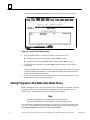
Storing Programs in Run Mode (RunĆModeĆStore)
Before attempting to store a logic program to a PLC in Run mode or to modify a running
program, you must first set the Logicmaster 90 Communications Window to Limited
mode. Also, we recommend a time setting of 50 ms for the window.
Note
Logicmaster 90 prohibits storing programs in RUN mode if the
Logicmaster 90 Communications Window is not set to Limited mode.
The mode of the Communications Window is set in the PLC Sweep Control screen. This
screen is accessed from the Logicmaster 90 Programming main screen by pressing , F3 ...
PLC Control and Status, and then F1 ... PLC Sweep Control.
3Ć8
Logicmaster 90Ć30 and Logicmaster 90Ć70 TCP/IPĆEthernet User's Manual Supplement-April 1996
GFKĆ1029B
Chapter
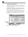
4 Network Utilities
4
section level 1 1
figure bi level 1
table_big level 1
This chapter describes the functions of the Network Utilities. These screens are used
primarily by the personnel responsible for the operation of the network. But the PLC
List screen is also very valuable to those using the Logicmaster 90-30 TCP/IP or
Logicmaster 90-70 TCP/IP software for programming and configuring the PLCs on the
network.
Selecting the Network Utilities
To select the Network Utility functions:
1.
From the Logicmaster 90 Main menu select the Logicmaster 90 Utilities by pressing
the F7 ... Logicmaster 90 Utilities function key. The following screen will be
displayed.
Figure 4-1. Logicmaster 90 Utilities Menu
GFK-1029B
4-1
4
2.
Select the Network Utility by pressing F1 ... Network Utility. The password screen
will then appear.
Figure 4-2. The Password Screen
Enter the password and press Enter. (The default password is netutil). The Network
Utilities Menu will appear.
Note
You can change the password in the F7 ... Set Password function in the
Network Utilities.
4-2
Logicmaster 90-30 and Logicmaster 90-70 TCP/IP-Ethernet User’s Manual Supplement–April 1996
GFK-1029B
4
Figure 4-3. Network Utilities Menu
From the Network Utilities menu the following screens can be selected:
Provides a list, entered by the user, of PLCs on the network. This list is
subsequently displayed within the Logicmaster 90 programming packages on the Select
PLC Connection screen.
Allows you to change the password used to enter the Network Utilities.
These screens are described in detail later in this chapter.
Note
If you have TCP Version 0.01 on the screen below, you should replace
the NETUTILT.EXE file in the LM90 directory with a newer version of
the file from the GE Fanuc bulletin board – 804-978-5458.
GFK-1029B
Chapter 4 Network Utilities
4-3
4
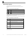
Network Utilities Operation
The keys used in the Network Utilities sub-menus are described below.
Function Keys. The table below describes the function keys used in the Network
Utilities.
Table 4-1. Use of the Function Keys in the Network Utilities
ÁÁÁ
ÁÁÁÁÁ
ÁÁÁÁÁÁÁÁÁÁÁÁÁÁÁÁÁÁÁÁ
ÁÁÁ
ÁÁÁÁÁ
ÁÁÁÁÁÁÁÁÁÁÁÁÁÁÁÁÁÁÁÁ
ÁÁÁ
ÁÁÁÁÁ
ÁÁÁÁÁÁÁÁÁÁÁÁÁÁÁÁÁÁÁÁ
ÁÁÁ
ÁÁÁÁÁ
ÁÁÁÁÁÁÁÁÁÁÁÁÁÁÁÁÁÁÁÁ
ÁÁÁ
ÁÁÁÁÁ
ÁÁÁÁÁÁÁÁÁÁÁÁÁÁÁÁÁÁÁÁ
ÁÁÁ
ÁÁÁÁÁ
ÁÁÁÁÁÁÁÁÁÁÁÁÁÁÁÁÁÁÁÁ
ÁÁÁ
ÁÁÁÁÁÁÁÁÁÁÁÁÁÁÁÁÁÁÁÁÁÁÁÁÁ
Key
F1
F2
F3
F4
F8
Name
clear
save
add
delete
GSMImp
Function
Clears values of the displayed list.
Saves the values of the displayed list.
Adds a PLC name to the PLC List.
Deletes a PLC name from the PLC List.
Special function to import PLC addressing information from GEnet System
manager.
Field Selection Keys. The four arrow keys (up, down, right,and left) are used to select a
field. The selected field is shown in reverse video.
Editing Keys. In cases where the selected field can be edited the following keys are used:
Table 4-2. Use of the Editing Keys in the Network Utilities
ÁÁÁÁÁÁ
ÁÁÁÁÁÁÁÁÁÁÁÁÁÁÁÁÁÁÁÁ
ÁÁÁÁÁÁ
ÁÁÁÁÁÁÁÁÁÁÁÁÁÁÁÁÁÁÁÁ
ÁÁÁÁÁÁ
ÁÁÁÁÁÁÁÁÁÁÁÁÁÁÁÁÁÁÁÁ
ÁÁÁÁÁÁ
ÁÁÁÁÁÁÁÁÁÁÁÁÁÁÁÁÁÁÁÁ
ÁÁÁÁÁÁ
ÁÁÁÁÁÁÁÁÁÁÁÁÁÁÁÁÁÁÁÁ
ÁÁÁÁÁÁ
ÁÁÁÁÁÁÁÁÁÁÁÁÁÁÁÁÁÁÁÁ
ÁÁÁÁÁÁ
ÁÁÁÁÁÁÁÁÁÁÁÁÁÁÁÁÁÁÁÁ
ÁÁÁÁÁÁ
ÁÁÁÁÁÁÁÁÁÁÁÁÁÁÁÁÁÁÁÁ
ÁÁÁÁÁÁ
ÁÁÁÁÁÁÁÁÁÁÁÁÁÁÁÁÁÁÁÁ
ÁÁÁÁÁÁ
ÁÁÁÁÁÁÁÁÁÁÁÁÁÁÁÁÁÁÁÁ
ÁÁÁÁÁÁ
ÁÁÁÁÁÁÁÁÁÁÁÁÁÁÁÁÁÁÁÁ
ÁÁÁÁÁÁ
ÁÁÁÁÁÁÁÁÁÁÁÁÁÁÁÁÁÁÁÁ
ÁÁÁÁÁÁ
ÁÁÁÁÁÁÁÁÁÁÁÁÁÁÁÁÁÁÁÁ
ÁÁÁÁÁÁÁÁÁÁÁÁÁÁÁÁÁÁÁÁÁÁÁÁÁÁ
Key
right arrow
left arrow
Ctrl-right arrow
Ctrl-left arrow
Delete
Insert
‘0’ - ‘9’
‘0’ - ‘9’
‘a’ - ‘f’
‘A’ - ‘F’
‘0’ - ‘9’
‘A’ - ‘Z’,
_(underscore)
Function
Moves to the cursor to the PLC ID field
Moves the cursor to the IP addr field.
Moves the cursor to the right. The cursor can not be moved beyond the maximum length. The cursor can not be moved to a position in the field such that a
space would result. There is no wrap around.
Moves the cursor to the left. There is no wrap around.
Deletes the character above the cursor.
Switches keyboard between Insert and Replace modes.
Keys allowed for decimal input.
Keys allowed for hexadecimal input. The ‘a’ - ‘f’ keys are converted to upper
case (‘A’ - ‘F’).
Keys allowed for alphanumeric strings.
Exiting a Screen. The Esc key is used to exit the current screen and return to the
previous screen or menu.
4-4
Logicmaster 90-30 and Logicmaster 90-70 TCP/IP-Ethernet User’s Manual Supplement–April 1996
GFK-1029B
4
PLC List Screen
When the PLC List screen is displayed the list of PLCs is read from a file. This file is used
by the Logicmaster 90 programming package to display the list of PLCs for connection.
You may clear or modify this list of PLCs on the screen but these changes are not
automatically written to the file. Press F2 save to write any changes to the file.
The PLC List screen is shown below.
Figure 4-4. PLC List Screen
Clear Function. To clear the list of PLCs on the screen, press F1 clear.
Save Function. To write the currently displayed list to the file, press F2 save.
Add Function. To add a PLC ID to the list, press F3 add, and enter a full 12-digit MAC
address. Press ENTER to add to the list. Refer to the section, “Adding an Entry to the
List” in Chapter 3 for more information.
Delete Function. To delete an entry from the list, position the cursor on the name and
press F4 delete.
GSMImp Function. To import addressing information for Series 90 PLCs previously
configured using the GEnet System Manager (GSM), press F8 (GSMImp). You will be
prompted to enter the location of the GSM root directory. Upon entering this
information, the GSM database will be searched for configured devices that support
TCP/IPEthernet communication. Matching entries will be added to the PLC list. See the
TCP/IP Ethernet Communications for the Series 90-70 PLC User’s Manual (GFK-1004) for
details about the GSM.
GFK-1029B
Chapter 4 Network Utilities
4-5
4
Set Password Screen
The Set Password screen allows you to change the password for the Network Utilities.
The screen displays the password prompt as shown below.
Figure 4-5. Set Password Screen
To change the password:
1.
Type in the current password at the Enter current password prompt and press Enter.
The New password prompt will be displayed.
Enter new password :
2.
Type in a new password and press Enter. The Verify password prompt will be
displayed.
Verify new password :
3.
Type in the new password and press Enter. The following messages will then be
displayed.
Password set
Press any key to continue ...
4.
4-6
Be sure to keep a secure record of the new password.
Logicmaster 90-30 and Logicmaster 90-70 TCP/IP-Ethernet User’s Manual Supplement–April 1996
GFK-1029B
Appendix A Quick Start Install Program (Series 90-70
Only)
A
What Does the Quick Start Program Install?
Logicmaster 90-70 TCP/IP-Ethernet software consists of:
H
H
H
GSM software for Ethernet Interface (IC697CMM741)
Beame & Whiteside TCP/IP stack (BW-Connect TCP) software
Logicmaster 90-70 TCP/IP Ethernet software
Quick Start installs these products together on one PC. Use it for the initial installation
only, not for upgrades.
Note
The GSM software is required for installation of the Series 90-70
Ethernet Interface (IC697CMM741) before Logicmaster 90-70
TCP/IP-Ethernet can communicate with the Interface.
Quick Start does not support installation of the GSM separately. If you wish to install the
GSM on a different PC than the one running Logicmaster 90-70 TCP/IP-Ethernet, do the
following.
1.
Use Quick Start to install the GSM, Beame & Whiteside, and Logicmaster TCP/IP
Ethernet software all together.
2.
Delete the C:\GSM directory and all files in it.
3.
Install the GSM on another PC using the instructions in GFK-1004.
The Quick Start Install Program uses NDIS drivers. It does not support:
H
H
H
H
H
Novell or other ODI based network software.
Other NDIS applications running on this PC.
Installation to the D: drive.
Installation from 5.25-inch diskettes.
Installation from the B: drive.
The Quick Start Install Program does not support upgrades. Quick Start looks for the
presence of Beame & Whiteside software on your PC. If it finds it, the Quick Start
installation will be aborted. If this happens, refer to “Troubleshooting” on page A-8.
GFK-1029B
A-1
A
Installation Diskettes
The following diskettes are supplied with the Logicmaster 90-70 TCP/IP Ethernet
Product. You must have all these diskettes in order to run this install program.
1 - Quick Start Install diskette.
1 - GSM diskette labeled Series 90-70 TCP/IP Ethernet Sw (IC651ENS042).
5 - Beame & Whiteside diskettes.
2 - Logicmaster 90 diskettes.
Before Running the Install Program
1.
Create a bootable DOS diskette!
If something goes wrong during this installation procedure, your computer may not
boot properly. You will need a boot diskette.
To create a bootable System Disk, place a floppy in a: drive. All data will be erased on
the floppy so start with a new floppy or one that you don’t need. Type:
C:\> format a:/s
(The formatting process will take a few minutes.)
2.
A-2
Complete the worksheet on page A-3.
Logicmaster 90-30 and Logicmaster 90-70 TCP/IP-Ethernet User’s Manual Supplement–April 1996
GFK-1029B
A
Worksheet
Network Adapter Card Information
For the following information, refer to your network adapter card user manual. For a list of cards that
are supported by Logicmaster TCP/IP, see Table A-1.
Network Adapter Card Make/Model:_____________
Network Adapter Driver Type:
NDIS
Hardware Interrupt for Network Adapter Card: _____________
I/OAddress for Network Adapter Card: ___________
Network Adapter Card configured for Shared Memory (Yes, No): ___________
Starting Address for Shared Memory (0 if No shared memory): _____________
Software Interrupt Vector:
7c
How is IP Address determined: User entered
Time Zone: _________________________________
IP Addresses
If you have an existing Ethernet Network that uses TCP/IP, then someone in your company takes care of
assigning IP Addresses. That person should be able to provide the following information.
IP Address of Network Adapter Card: _____________ If you have an isolated network you can use
the IP address 003.000.000.001 for your Network Adapter Card. Make sure this address is not
already being used by another station.
Subnet Mask: If needed, use the mask supplied by your System Administrator. If you don’t know
the mask, use 255.255.255.000: _________________
IP Address of Gateway (if required): _____________
IP Address of Domain Name Service (if required): ____________
IP Address of Trivial Name Server(if required): _____________
P Address of Time Server(if required): _____________
IP Address of BOOTP Server(if required): _____________
Company domain name: ___________ If you don’t have a company domain name, use a three-letter
code for the company followed by .com (all in lower case). Example: abc.com
GFK-1029B
Appendix A Quick Start Installation Instructions
A-3
A
ÁÁÁÁÁ
ÁÁÁÁÁÁÁÁ
ÁÁÁÁ
ÁÁÁÁ
ÁÁÁÁÁÁÁ
ÁÁÁ
ÁÁÁÁ
ÁÁÁÁ
ÁÁÁÁÁ
ÁÁÁÁÁÁÁÁ
ÁÁÁÁ
ÁÁÁÁ
ÁÁÁ
ÁÁÁÁ
ÁÁÁ
ÁÁÁÁ
ÁÁÁÁ
ÁÁÁÁÁ
ÁÁÁÁÁÁÁÁ
ÁÁÁÁ
ÁÁÁÁ
ÁÁÁ
ÁÁÁÁ
ÁÁÁ
ÁÁÁÁ
ÁÁÁÁ
ÁÁÁÁÁ
ÁÁÁÁÁÁÁÁ
ÁÁÁÁ
ÁÁÁÁ
ÁÁÁ
ÁÁÁÁ
ÁÁÁ
ÁÁÁÁ
ÁÁÁÁ
ÁÁÁÁÁ
ÁÁÁÁÁÁÁÁ
ÁÁÁÁ
ÁÁÁÁ
ÁÁÁ
ÁÁÁÁ
ÁÁÁ
ÁÁÁÁ
ÁÁÁÁ
ÁÁÁÁÁ
ÁÁÁÁÁÁÁÁ
ÁÁÁÁ
ÁÁÁÁ
ÁÁÁ
ÁÁÁÁ
ÁÁÁ
ÁÁÁÁ
ÁÁÁÁ
ÁÁÁÁÁ
ÁÁÁÁÁÁÁÁ
ÁÁÁÁ
ÁÁÁÁ
ÁÁÁ
ÁÁÁÁ
ÁÁÁ
ÁÁÁÁ
ÁÁÁÁ
ÁÁÁÁÁ
ÁÁÁÁÁÁÁÁ
ÁÁÁÁ
ÁÁÁÁ
ÁÁÁ
ÁÁÁÁ
ÁÁÁ
ÁÁÁÁ
ÁÁÁÁ
ÁÁÁÁÁÁÁÁ
ÁÁÁÁ
ÁÁÁ
ÁÁÁ
ÁÁÁÁ
ÁÁÁÁ
ÁÁÁÁÁ
ÁÁÁÁ
ÁÁÁÁ
ÁÁÁÁÁ
ÁÁÁÁÁÁÁÁ
ÁÁÁÁ
ÁÁÁÁ
ÁÁÁ
ÁÁÁÁ
ÁÁÁ
ÁÁÁÁ
ÁÁÁÁ
ÁÁÁÁÁ
ÁÁÁÁÁÁÁÁ
ÁÁÁÁ
ÁÁÁÁ
ÁÁÁ
ÁÁÁÁ
ÁÁÁ
ÁÁÁÁ
ÁÁÁÁ
ÁÁÁÁÁ
ÁÁÁÁÁÁÁÁ
ÁÁÁÁ
ÁÁÁÁ
ÁÁÁ
ÁÁÁÁ
ÁÁÁ
ÁÁÁÁ
ÁÁÁÁ
ÁÁÁÁÁ
ÁÁÁÁÁÁÁÁ
ÁÁÁÁ
ÁÁÁÁ
ÁÁÁ
ÁÁÁÁ
ÁÁÁ
ÁÁÁÁ
ÁÁÁÁ
ÁÁÁÁÁ
ÁÁÁÁÁÁÁÁ
ÁÁÁÁ
ÁÁÁÁ
ÁÁÁ
ÁÁÁÁ
ÁÁÁ
ÁÁÁÁ
ÁÁÁÁ
ÁÁÁÁÁ
ÁÁÁÁÁÁÁÁ
ÁÁÁÁ
ÁÁÁÁ
ÁÁÁ
ÁÁÁÁ
ÁÁÁ
ÁÁÁÁ
ÁÁÁÁ
ÁÁÁÁÁ
ÁÁÁÁÁÁÁÁÁÁÁÁ
ÁÁÁÁÁÁÁÁ
ÁÁÁÁ
ÁÁÁÁÁÁÁÁÁÁÁÁÁÁÁÁÁÁÁÁ
ÁÁÁÁ
ÁÁÁ
ÁÁÁÁ
ÁÁÁ
ÁÁÁÁ
ÁÁÁÁ
ÁÁÁÁÁÁÁÁÁÁÁÁ
ÁÁÁÁÁÁÁÁÁÁÁÁÁÁÁÁÁÁÁÁ
Table A-1. Network Adapter Cards Supported
Vendor
3Com
3Com
3Com
3Com
SMC/Western
Digital
SMC/Western
Digital
SMC/Western
Digital
Intel
Xircom
Vendor Model
[Restrictions]
Driver
H/W
IRQ
I/O
Addr
Shared
Memory
Etherlink II (3C503)
Etherlink 3 (3C509)
Etherlink 16 (3C507)
Etherlink/MC(3C523)
[ELNKMC.SYS v 2.0 min]
EtherCard PLUS
NDIS
NDIS
NDIS
NDIS
3
10
3
3
300
300
300
300
No
No
No
No
NDIS
3
280
EtherCard PLUS Elite 16
NDIS
3
EtherCard PLUS/A
NDIS
3
Intel 82593
NDIS
15
PE2
NDIS
7
[PE2NDIS.EXE v 1.44 min]
Xircom
PE3
NDIS
7
IBM
PCMCIA
NDIS
5
NDIS supporting network card
Vendor-dependent
Start
Addr
Buffer
Space
S/W Int.
Vector
(deflt)
0
0
0
0
10000
10000
10000
10000
7c
7c
7c
7c
Yes
d000
10000
7c
280
Yes
d000
10000
7c
280
Yes
d000
10000
7c
300
378
No
No
0
0
10000
10000
7c
7c
378
300
No
Yes
0
d4000
10000
10000
7c
7c
Notes:
The values in this table are valid if you are using the default settings for the Ethernet Adapter.
Logicmaster 90 software requires as much memory as possible. A buffer space setting of 10000 leaves
the most memory for Logicmaster 90. If you are running Beame & Whiteside Connect software with
Windows applications, increase buffer space to 26,000 (the Beame & Whiteside default value).
A-4
Logicmaster 90-30 and Logicmaster 90-70 TCP/IP-Ethernet User’s Manual Supplement–April 1996
GFK-1029B
A
Running the Install Program
1.
The Quick Start install program can only be run from the C:\TCP_TEMP
directory. To set up the C:\TCP_TEMP directory:
A. Create the directoryC:\TCP_TEMP.
D
D
Go to the C:\ root directory.
Type: MKDIR TCP_TEMP
B. Copy all files from the Quick Start Installation disk to the C:\TCP_TEMP
directory. To do this, type:
Copy a:*.*
2.
c:\tcp_temp
Execute the Batch file I_LMTCP in the TCP_TEMP directory. To do this, go
to the C:\TCP_TEMP directory and type:
I_LMTCP
The install program will back up your AUTOEXEC.BAT file to AUTOEXEC.ADG and
back up your CONFIG.SYS file to CONFIG.ADG.
The install program then loads simple AUTOEXEC.BAT and CONFIG.SYS files,
which are modified by the subsequent steps so they will work with Logicmaster
TCP/IPEthernet and the GSM.
The software will prompt you for more information. To complete the installation,
respond to the prompts as listed below and on page A-6.
Prompts for the GE Fanuc Series 90-70 TCP/IP Ethernet Software:
GSMCFG pathname - accept the default (press the Enter key).
Choose the type of Ethernet adapter you are using - enter the
number of your Ethernet adapter (5 - 12 are Ethernet adapters). If your Ethernet
adapter is not on the list, enter 12.
GFK-1029B
Appendix A Quick Start Installation Instructions
A-5
A
Prompts for the Beame & Whiteside TCP/IP Software:
Source drive for software - up/down arrow to drive, press Enter key.
Destination drive for software - you must put it on the C drive
What is the default directory for the software - accept the default
(press the Enter key).
Select the Ethernet adapter you are using – press the up/down arrow
key to find the adapter, then press the Enter key. (Note: If you selected one of the
Ethernet adapters named on the Ethernet Adapter selection screen of the GSM
portion of the install program, be sure to select the same adapter here in the Beame
& Whiteside list. If you selected “Other ” on the GSM screen, select the correct
adapter here. If you selected an SMC/Western Digital adapter in the GSM
installation, use the more specific entry listed here.)
Driver type to use - down arrow to NDIS, press the Enter key.
(FULL PAGE SCREEN) enter Ethernet adapter and IP addressing
information - use the Worksheet you filled out.
Editing the Full Page Screen
Use the Tab key to change from field to field.
When a pop-down menu appears, use the arrow key to make a selection. Press
Enter.
Do not press Shift+ Tab or Esc. Doing so will cause you to exit this screen.
Three digits must be entered for each of the IP address fields.
If you make a mistake on a field, you can cycle around again (by using the Tab key)
to make corrections.
If you exit this screen prematurely, continue with the installation program. When
you are finished, see“Troubleshooting” for instructions to return to this screen.
Enter your company domain name - get from Preliminary worksheet.
Modify Real System Files - Yes.
Do windows installation now - No.
Note
The next three prompts are for your information only.
Prompts for the GE Fanuc Logicmaster 90-70 Ethernet TCP/IP software:
Destination drive for software - must use “C”.
Registration information - Accept and also accept confirmation if correct.
Modify AUTOEXEC.BAT and CONFIG.SYS - Yes.
Prompt for coordination of the installations:
Enter the Ethernet adapter you are using - Enter the appropriate letter.
(Note: This should be the same adapter you selected in the GSM and B&W. If your
adapter is not on this list, use “Other ”.)
A-6
Logicmaster 90-30 and Logicmaster 90-70 TCP/IP-Ethernet User’s Manual Supplement–April 1996
GFK-1029B
A
3.
Edit the CONFIG.SYS file.
A. Find the line
DEVICE = C:\BWTCP\NDIS\PROTMAN.DOS ...
B. Change all lines below that line that start with
DEVICE=C:\BWTCP\ ...
to
DEVICEHIGH=C:\BWTCP\ ...
4.
Editthe C:\LANMAN.DOS\PROTOCOL.INI file.
The text below is a sample PROTOCOL.INI file for the Etherlink MC adapter. Three
of the four labels [in brackets] are the same for all PROTOCOL.INI files produced by
this install program: [ProtMan], [ETHDEV], and GEFNDIS]. The fourth label, which
is located below the [Protman] label, is different for each type of adapter. It is
[ELNKMC] in this example.
After you have completed the installation, you need to check this file and make sure
of the following. Under [ETHDEV] label and the [GEFNDIS] label there is a line that
begins ”Bindings = ....”. The characters to the right of the equal sign must match
exactly the label in brackets located below the [ProtMan] label. For this example the
name is “ELNKMC.”
Sample contents of PROTOCOL.INI are shown below.
[ProtMan]
DriverName=PROTMAN$
[ELNKMC]
DRIVERNAME = ELNKMC$
[ETHDEV]
DriverName=ETHDEV27
Bindings=ELNKMC
[GEFNDIS]
DRIVERNAME = GEFNDIS$
BINDINGS = ELNKMC
MAX_RX_SIZE = 560
NUM_RX_BUFS = 8
5.
GFK-1029B
Reboot your computer. Press Control-Alt-Delete or cycle power.
Appendix A Quick Start Installation Instructions
A-7
A
Troubleshooting Quick Start Install Problems
Case1: Your computer will not reboot or, after successfully rebooting, will not run
Logicmaster software.
Make the following change to CONFIG.SYS to free more memory.
Note
If your computer will not reboot, you will need to reboot the computer
using the boot disk you created before beginning the installation.
Change the line
DEVICE=\DOS\EMM386.EXE RAM 1024
to DEVICE=\DOS\EMM386.EXE noems
then reboot and try again.
Case 2: If you aborted at any time during the installation procedure, the installation will
not work properly and you will need to start over.
Case 3: If you prematurely exited the Full-Page Beame & Whiteside screen, do the
following to return to it.
Disk #1
a. Insert Beame & Whiteside diskette #1 into drive A.
b. From the C: prompt, type a:bwinstall
Proceed with the following selections.
- Select your source drive.
- Select “Change Network Driver”.
- Select your destination drive.
- Enter destination directory.
- For the prompt, “Do you want to use existing NDIS information?”
Enter No.
- Select your network adapter card.
- Select NDIS Driver Type.
Disk #2
a. When the Full-Page Screen appears, make the desired changes.
b. Press F10 to accept changes.
c. For the prompt “Modify real system files?” Enter NO.
d. Proceed through the comment messages.
When you have finished the changes to the Beame & Whiteside setup, reboot
your computer.
A-8
Logicmaster 90-30 and Logicmaster 90-70 TCP/IP-Ethernet User’s Manual Supplement–April 1996
GFK-1029B
A
Case 4: The installation aborted because Beame & Whiteside Connect was found on your
PC.
If you made a mistake in Quick Start Install and are starting over:
a.DeleteC:\LANMAN.DOS\PROTOCOL.INI
b. Delete C:\BWTCP\*.*
c. Delete C:\BWTCP\NDIS\*.*
d. Redo the Quick Start Install.
If you are upgrading the GSM or Logicmaster 90-70 TCP/IP Ethernet on a PC
with a working installation, do not use the Quick install program. Use the GSM,
Beame & Whiteside, or Logicmaster 90-70 disk(s) with the associated install
routine.
Related Documents:
See GFK-1029 for instructions on installing Logicmaster 90-70 TCP/IP Ethernet.
See GFK-1273 for instructions on installing the TCP/IP software.
See GFK-1004 for instructions on installing the GSM.
GFK-1029B
Appendix A Quick Start Installation Instructions
A-9
Index
A
Accessing the PLC List Screen, 3-1
Adding an entry to the PLC list, 3-4
Assigning PLC IDs, 3-4
AUTOEXEC.BAT, 2-6, 2-9, 2-11, A-5, A-6
G
GEnet System Manager software, 1-1, 1-2,
4-5, A-1, A-5
GSM
See also GEnet System Manager
Installing, 2-2
GSMImp function, 4-5
B
I
Baud rate, 2-8
ID: field, identifying connected PLC, 3-5
Bulletin board, 3-3
Identifying PLCs on the Network, 3-1
Installation, Logicmaster 90-70 Ethernet
software, A-1
C
Catalog numbers, 1-3
CONFIG.SYS, 2-6, 2-9, 2-10, A-5, A-6, A-7,
A-8
Configuring the TCP/IP–Ethernet interfaces, 2-2
Contents of the software packages, 1-3
D
Default gateway, 2-7
Direct Ethernet connection, 1-1
block diagram, 2-3
installing Beame & Whiteside software
for, 2-5
E
Editing keys, 4-4
Establishing Communications, 3-6
Exiting a Screen, 4-4
Installing and Starting-Up the Software,
2-1
Installing Beame & Whiteside software
for Direct Ethernet connection, 2-5
for SLIP communications, 2-7
Installing GSM, 2-2
Installing Logicmaster 90 TCP/IP software, 2-9
L
Logicmaster 90
main menu, 3-1
Network Utilities menu, 3-3, 4-3
PLC Communications Options Menu,
2-13
PLC List screen, 3-4, 4-5
Programmer Setup menu, 3-6
Select PLC Connection screen, 3-7
Set Password screen, 4-6
Setup File Editor menu, 2-12
Utilities menu, 3-2, 4-1
Logicmaster 90-70, main menu, 2-12
N
NDIS drivers, A-1
F
Field selection keys, 4-4
Free conventional memory, checking, 2-2
Full Page screen, editing, A-6
Function keys, Network Utilities, 4-4
GFK-1029B
Network adapter cards, A-4
Network Utilities menu, 3-3, 4-3
Network Utilities operation, 4-4
P
Password, default for network utilities, 3-3
Index-1
Index
Password screen, 3-2
Ping utility, 2-5, 2-6, 2-8
PLC Communications Options menu, 2-13
PLC IDs
adding, 4-5
assigning, 3-4
S
Select PLC Connection Screen, 3-7
Selecting the Network Utilities, 4-1
Setup File Editor menu, 2-12
PLC List, 3-1
SLIP, 1-1
installing Beame & Whiteside software
for, 2-7
PLC List Screen, 3-4, 4-5
SLIP connection, block diagram, 2-3
PLC List screen, 4-5
Starting the Logicmaster 90 software, 2-12
Programmer Setup menu, 3-6
PROTOCOL.INI, 2-11, A-7
Storing Programs in Run Mode, 3-7
Subnetwork mask, 2-7, A-3
T
Q
Quick guide to the manual, 1-4
Quick Start Install program, A-1
running, A-5
worksheet, A-3
Troubleshooting, Quick Start Install program, A-8
U
Users of the software package
Network personnel, 1-4
PLC logic programming personnel, 1-4
R
Requirements for Running the Software,
2-2
Run-Mode-Store, 3-7
Index-2
W
Worksheet, for using Quick Start Install
program, A-3
GFK-1029B