1
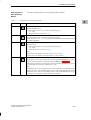
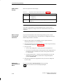
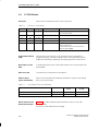
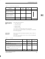
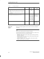
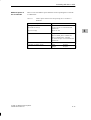
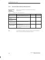
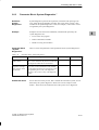
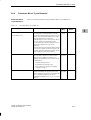
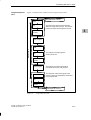
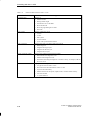
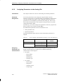
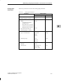
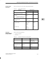
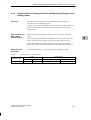
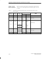
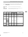
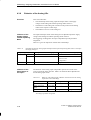
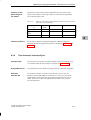
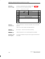
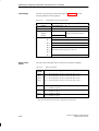
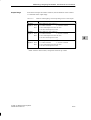
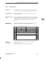
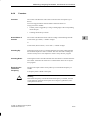
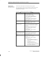
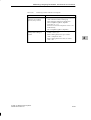
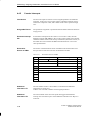
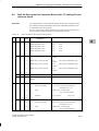
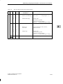
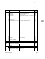
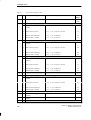
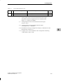
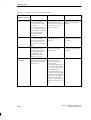
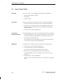
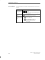
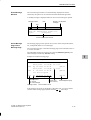
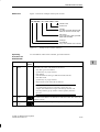
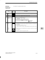
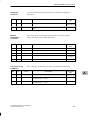
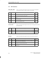
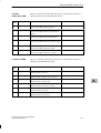
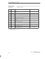
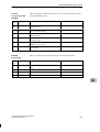
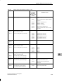
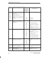
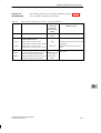
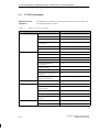
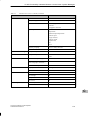
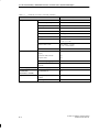
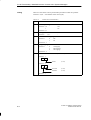
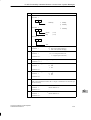
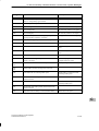
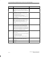
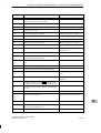
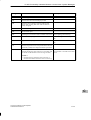
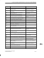
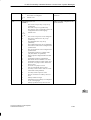
I/O Diagnostics
Reaction to
Diagnostic
Messages
Table 5-4
The diagnostic messages listed in Table 5-4 refer to Table 5-3.
Table 5-4 lists the diagnostic messages and also possible reactions of the user.
Diagnostic Messages and Possible Responses
Reason for the
Diagnostic Message
Source of Error
Response of the Module
Possible Elimination
Module not
assigned
parameters
During the startup of the
module, if no parameters
were assigned to the C7
CPU. The “module error” bit
is not set if no further error
exists.
Report to C7 CPU that the
Assign parameters to module
module is working with
default parameters (no
channel-specific module
diagnostics, no hardware and
diagnostic interrupts).
Module fault
Collective error (except no
The error is set/reset with the See error under the grouping
module parameters) of all set subordinate diagnostic bits. If “module error” (Table 5-3)
diagnostic bits
the diagnostic interrupt has
been assigned, one will be
generated.
Internal error
The error bit is set
simultaneously with the error
bits “Watchdog”, “EEPROM
error”, or “ADC error”. In
addition, the watchdog is
activated with “EEPROM
error”.
Watchdog
The watchdog error is
identified after an internal
reset of the module. The
watchdog error can arise as
the result of an EPROM or
general module error.
With watchdog, the module
adopts a safe state. 0 V is
output, the measured values
become 7FFFh and the
counter values become
FFFFh/FFFFFFh.
The error cannot be corrected
by the user.
The module can only be
restarted after a reset on the
bus (restart C7 CPU).
EEPROM error
The error is identified after
resetting the module during
the reading of the calibration
values for the compensation
of the offset error of the
analog I/O from the serial
EEPROM.
The module adopts a safe
state. 0 V is output, the
measured values become
7FFFh and the counter values
become FFFFh/FFFFFFh.
The error cannot be corrected
by the user.
The module can only be
restarted after a reset on the
bus (restart C7 CPU) or the
analog I/O must be
recalibrated at the
manufacturer’s factory
(device exchange).
External error
The error bit is set when
Refer to the grouping
Refer to the grouping
channel-specific errors of the “External error” in Table 5-3. “External error” in Table 5-3.
analog inputs or outputs
occur.
Channel error
A channel causes an error.
Refer to the grouping
Refer to the grouping
The diagnosis of the error“External error” in Table 5-3. “Channel” in Table 5-3.
causing channel is activated
by the parameter assignment.
C7-626 / C7-626 DP Control Systems
C79000-G7076-C627-01
See error under the grouping
“Internal error” (Table 5-3)
5-9
5