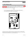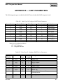
1
Field Automation Systems HART INTERFACE PROGRAMS User Manual Form A4650 March 1999 Part Number D301069X012 HART Program User Manual Revision Tracking Sheet March 1999 This manual may be revised periodically to incorporate new or updated information. The revision date of each page is indicated at the bottom of the page opposite the page number. A major change in the content of the manual also changes the date that appears on the front cover. Listed below is the revision date of each page. Page Revision All 3/99 Fisher, Fisher-Rosemount, and Managing The Process Better are marks owned by the Fisher-Rosemount group of companies. HART is a registered trademark of the HART Communication Foundation. All other marks are the property of their respective owners. Fisher Controls International, Inc. 1994-1999. All rights reserved. Printed in the U.S.A. While this information is presented in good faith and believed to be accurate, Fisher Controls does not guarantee satisfactory results from reliance upon such information. Nothing contained herein is to be construed as a warranty or guarantee, express or implied, regarding the performance, merchantability, fitness or any other matter with respect to the products, nor as a recommendation to use any product or process in conflict with any patent. Fisher Controls reserves the right, without notice, to alter or improve the designs or specifications of the products described herein. ii Rev 3/99 HART Program User Manual Table of Contents SECTION 1 — INTRODUCTION.............................................................................. 1-1 1.1 1.2 1.3 1.4 1.5 1.6 1.7 1.8 Organization of Manual .............................................................................................................1-1 Section 1 – Contents ..................................................................................................................1-2 HART Interface Cards and HART Interface Modules ..............................................................1-3 Additional Information ..............................................................................................................1-4 Overview....................................................................................................................................1-5 HART Interface Card Program..................................................................................................1-6 HART Interface Module Program .............................................................................................1-7 Program Files Supplied..............................................................................................................1-8 SECTION 2 — HARDWARE INSTALLATION...................................................... 2-1 2.1 Section contents .........................................................................................................................2-1 2.2 RAM Backup and Restoration Procedures ................................................................................2-2 2.2.1 RAM Backup with GV101 Configuration Software.............................................................2-2 2.2.2 RAM Backup Procedure using ROCLINK Software ...........................................................2-5 2.2.3 After Installing Components Using GV101..........................................................................2-6 2.2.4 After Installing Components using ROCLINK.....................................................................2-8 2.3 HART Interface Module............................................................................................................2-9 2.3.1 Installing a HART Interface Module ..................................................................................2-10 2.3.2 HART Interface Module Wiring .........................................................................................2-11 2.3.3 Testing the HART Interface Module ..................................................................................2-13 2.4 HART Interface Card ..............................................................................................................2-14 2.4.1 Installing a HART Interface Card .......................................................................................2-15 2.4.2 HART Interface Card Wiring..............................................................................................2-17 2.4.3 Testing the HART Interface Card .......................................................................................2-18 2.5 Hart Interface Card and Module Specifications ......................................................................2-20 SECTION 3 DOWNLOADING THE HART USER PROGRAM.......................... 3-1 3.1 Downloading Requirements ......................................................................................................3-2 3.1.1 HART Card in a ROC306 or ROC312..................................................................................3-2 3.1.2 HART Module in a ROC312 or ROC364.............................................................................3-3 3.1.3 HART Module in a FloBoss 407...........................................................................................3-4 3.1.4 Viewing Available Memory..................................................................................................3-5 3.1.5 Memory Segments.................................................................................................................3-6 3.2 Downloading Procedures...........................................................................................................3-9 3.2.1 Downloading HART Using ROCLINK................................................................................3-9 3.2.2 Downloading HART to RAM Using GV101......................................................................3-11 3.2.3 Downloading HART to FloBoss 407 Flash Memory Using GV101 ..................................3-15 Rev 3/99 iii HART Program User Manual SECTION 4 — CONFIGURING HART POINTS .................................................... 4-1 4.1 Configuring HART Points Using ROCLINK............................................................................4-1 4.2 Configuring HART Points Using GV101..................................................................................4-3 SECTION 5 — CONFIGURING THE HART DEVICE.......................................... 5-1 5.1 Configuring the HART Device using ROCLINK .....................................................................5-1 5.1.1 Slot Variables Using ROCLINK...........................................................................................5-6 5.1.2 Advanced Features Using ROCLINK...................................................................................5-7 5.1.3 Alarms/Device Status Using ROCLINK...............................................................................5-9 5.2 Configuring the HART Device using GV101 .........................................................................5-12 SECTION 6 — HART HOST OPERATION............................................................. 6-1 6.1 HART Commands .....................................................................................................................6-1 6.1.1 HART Message Frames ........................................................................................................6-2 6.2 Full Update ................................................................................................................................6-5 6.2.1 Initiating a Full Update Using ROCLINK ............................................................................6-5 6.2.2 Initiating a Full Update Using GV101 ..................................................................................6-5 6.3 Polling Methods.........................................................................................................................6-6 6.4 Writing Parameters ....................................................................................................................6-7 6.4.1 Writing Parameters Using ROCLINK ..................................................................................6-7 6.4.2 Writing Parameters Using GV101 ........................................................................................6-7 6.5 Clearing the Configuration Change Bit .....................................................................................6-8 6.5.1 Clearing the Configuration Change Bit using ROCLINK ....................................................6-8 6.5.2 Clearing the Configuration Change Bit using GV101 ..........................................................6-8 SECTION 7 — USING HART PARAMETERS........................................................ 7-1 7.1 Using HART Parameters with the ROC....................................................................................7-1 7.2 Using HART with ROC Protocol ..............................................................................................7-1 7.3 Using HART With Modbus Protocol ........................................................................................7-1 APPENDIX A — SOFT POINT MAPPING ............................................................. A-1 APPENDIX B — HART PARAMETERS ................................................................. B-1 INDEX .............................................................................................................................I-1 iv Rev 3/99 HART Program User Manual SECTION 1 — INTRODUCTION The Remote Operations Controllers (ROCs) and FloBoss units use standard Highway Addressable Remote Transducer (HART®) Protocol commands to request and write parameters to a HART Slave device. The HART Protocol relies on the Bell 202 Frequency Shift Keying (FSK) standard to superimpose digital signals at a low level on top of the 4 to 20mA. The low-level FSK sine-wave signal transmits digitally. The HART Protocol allows both analog and digital communication signals to be transmitted simultaneously on the same wiring allowing two-way field communications from the Host to the HART device. Process Variable and control signal information may be transmitted using the 4 to 20mA while additional measurements, device configuration, parameters, and calibration travel over the digital channel. 1.1 ORGANIZATION OF MANUAL This manual is organized into the following major sections: ♦ ♦ ♦ ♦ ♦ ♦ ♦ ♦ ♦ ♦ ♦ Table of Contents Section 1 Introduction Section 2 Hardware Installation Section 3 Downloading the HART User Program Section 4 Configuring the HART Points Section 5 Configuring the HART Device Section 6 HART Host Operation Section 7 Using HART Parameters Appendix A Soft Point Mapping Appendix B HART Parameters Topical Index Table of Contents Lists each section and information contained in that section of the document. Section 1 Introduction describes this manual and mentions related manuals. This section also provides a summary of the HART user program, hardware overview, and lists the HART user programs. Section 2 Hardware Installation provides information concerning installation and wiring of the HART Card and HART Modules. This section also includes testing information. Section 3 Downloading the HART User Program describes how to view available memory, how to select and how to download the correct HART User Program to the ROC or FloBoss. Rev 3/99 1-1 HART Program User Manual Section 4 Configuring the HART Points provides information detailing how to configure the HART Points. Section 5 Configuring the HART Device provides information detailing how to configure the HART slave device. Section 6 HART Host Operation provides information detailing how to perform a full update, polling methods, writing parameters to the HART device, and clearing the configuration change bit. Section 7 Using HART Parameters provides information on how the HART parameters are referenced in the ROC/FloBoss, accessed using opcodes, and used in conjunction with Modbus. Appendix A Soft Point Mapping provides information detailing how the HART parameters can be mapped to the ROC soft points. Appendix B HART Parameters lists the ROC point types associated with the HART User Program. Topical Index Lists alphabetically the items contained in this manual, including the section and page number. NOTE “ROC” may occasionally be used in this manual to stand for both the ROC and FloBoss products. The FloBoss is essentially a specialized Remote Operations Controller (ROC). 1.2 SECTION 1 – CONTENTS This section includes: Information HART Interface Cards and HART Interface Modules Additional Information Overview HART Interface Card Program HART Interface Module Program Program Files Supplied 1-2 Section 1.3 1.4 1.5 1.6 1.7 1.8 Page Number 1-3 1-4 1-5 1-6 1-7 1-8 Rev 3/99 HART Program User Manual 1.3 HART INTERFACE CARDS AND HART INTERFACE MODULES The ROC or FloBoss and HART devices create a Host/Slave network. The ROC or FloBoss is the Host and each HART device is a Slave. There are two ways to send and receive HART messages between a ROC and HART devices, depending on the type of ROC/FloBoss and HART interface being used. HART Interface Card — The way first uses one HART Interface Card installed in a: ♦ ROC306 or ROC312 with a ROCPAC, firmware version 1.10. ♦ ROC306 or ROC312 with a FlashPAC, firmware version 2.0 or 2.1. HART Interface Modules — The second way uses one or more HART Interface Modules (sometimes called HART I/O Modules or HART Modules) installed in a: ♦ ♦ ♦ ♦ ROC312 with a ROCPAC, firmware version 1.10. ROC364 with a ROCPAC, firmware version 1.70. ROC312 or ROC364 with a FlashPAC, firmware version 2.0 or 2.1. FloBoss 407 with firmware version 1.04 or 1.06. NOTE In the case of the ROC312, it is not possible to use both a HART Interface Card and HART Interface Modules. One or the other must be chosen. Either option requires the correct HART user program to be loaded into the ROC. NOTE ROCLINK Configuration Software is required when using a ROC with a FlashPAC, or a FloBoss 407 with firmware version 1.06. For ROCs with a ROCPAC or a FloBoss 407 with firmware version 1.04, either the GV101 or the ROCLINK Configuration Software may be used. NOTE In most cases, the FloBoss 407 and ROC300-series units are identical in operation. Unless otherwise noted, the descriptions and procedures in this manual apply to all FloBoss and ROC types. In areas where the operation differs, the differences are described. Rev 3/99 1-3 HART Program User Manual 1.4 ADDITIONAL INFORMATION This document is intended to be used in conjunction with the following manuals and Web sites to assist in downloading and configuration. The physical (hardware) aspects of the FloBoss and ROC units are contained in their respective instruction manuals. Type RL101 ROCLINK Configuration Software User Manual (Form A6051) – Part Number D301101X12 GV101 Configuration Software User Manual (Form A4194) – Part Number D301058X012 Type ROC306/312 Remote Operations Controller Instruction Manual (Form A4630) – Part Number D301059X12 Type ROC364 Remote Operations Controller Instruction Manual (Form A4193) – Part Number D301060X12 FloBoss 407 Flow Manager Instruction Manual (Form A6013) – Part Number D301080X12 ROC Protocol User Manual (Form A4199) – Part Number D301053X12 www.ccsi.com/hart www.fieldbus.com/hart 1-4 Rev 3/99 HART Program User Manual 1.5 OVERVIEW ROC and FloBoss units use the standard HART protocol commands to request and write parameters to a HART device. HART travels over low signal frequencies (1200 and 2200Hz) which restricts transmissions to 1200 baud rate. When data is transmitted, 1200Hz represents a “1” state and 2200Hz represents a “0” state. Each message passed between a field device (Slave) and the Host includes the ROC Address and the destination Slave Address of the HART device, Device Status, and series of bytes representing the Commands sent by the Host. HART Host Commands are detailed in Section 6. The Host transmits a voltage signal and the Slave responds with a current signal. Each response message received from the HART Slave device contains information used to indicate problems with the device or communication errors. The Command Response or Response Code reports communication problems or problems with the HART Command the Slave received. The Device Status field displays the specific condition of the HART field device. When loaded into RAM, a HART program can use the following configuration software for configuring and monitoring HART points and devices. ♦ ROCLINK Configuration Software version 2.0 or 2.1. ♦ GV101 Configuration Software version 1.63. NOTE ROCLINK Configuration Software is required when using the HART program in a ROC with a FlashPAC, or in a FloBoss 407 with firmware version 1.06. For ROCs with a ROCPAC or a FloBoss 407 with firmware version 1.04, either the GV101 or the ROCLINK Configuration Software may be used. The HART parameters are referenced in the ROC the same as standard point type parameters by Type, Logical number, and Parameter (TLP). Each input and output has a unique Point Number to identify the input or output. Each I/O Point Type must be individually configured. This allows parameters such as a HART Primary Variable to be assigned as an input to an AGA Flow Calculation, a Process Variable or Process Value for a PID loop, a variable to display on a Local Display Panel, or a variable for any other ROC function. Two point types are added to the ROC protocol by a HART program: ♦ Point Type 30 – HART Point Configuration Parameters ♦ Point Type 31 – HART Device Configuration Parameters Refer to Appendix B for a complete list of the parameters associated with these HART point types. Rev 3/99 1-5 HART Program User Manual 1.6 HART INTERFACE CARD PROGRAM The HART Interface Card Program allows a ROC306 or ROC312 with an installed HART Interface Card to communicate with HART devices. Using HART digital communications, up to four measurements (Dynamic Variables) can be communicated in a single message. Other HART device specific transmitter variables may also be read. The HART Card allows both digital and analog signals through the ROC analog inputs. Each of the three built-in analog inputs (AIs) on the ROC306/ROC312 can be configured as a HART Point. Once a built-in analog input is configured as a HART Point, it can communicate either in the point-to-point mode or in the multi-drop mode to HART devices. In point-to-point mode, digital communications are superimposed on the 4 to 20 milliamp analog signals (which can still measure the Process Variable) through a built-in analog input. This mode allows communications with one HART device per built-in analog input point and maximizes polling speed. In point-to-point mode, all HART field devices have an address of 0. In multi-drop mode, several HART devices are connected to a single communications line. As many as five HART devices (limited by the total current consumption of the devices) can be connected in parallel to a single built-in analog input. Like the point-to-point mode, digital communications are superimposed on the current signals; however, the analog signal is used only to measure the current consumed by all HART devices in the multi-drop loop. Communications are restricted to digital transmissions as the loop current is fixed at a minimum value and no longer has meaning relative to the process. The digital transmissions contain the values read from the HART device. Multiple field devices may be physically connected (in parallel) to the same pair of wires when installed. When all three built-in analog input channels are used in multi-drop mode and five HART devices are wired to each input channel, a ROC306/ROC312 with a Hart Card can support a maximum of 15 HART devices. In multi-drop mode, HART field devices have an address of 1 through 15, and each device sets its output current to a fixed value (typically 4 mA). The ROC HART application sends a message to all multi-dropped devices, telling the HART device with a certain tag name to respond. Therefore, the Address of that HART device must match the Device Tag as defined in the Config HART Point screen. If the Device Tag of the HART device (typically set by a handheld communicator) does not match the Device Tag set in the Config Hart Point screen, the HART device will not respond. 1-6 Rev 3/99 HART Program User Manual 1.7 HART INTERFACE MODULE PROGRAM The HART Interface Module Program allows a ROC312, ROC364, or a FloBoss 407 unit with one or more installed HART Interface Modules to communicate with HART devices. The 4mA to 20mA analog signal is ignored when using a HART Module and communications are limited to digital signals only. When using a HART module, the HART module polls the HART device and temporarily stores the data in the HART module. The HART User Program polls the HART module and stores the data into the user defined point types. If the HART User Program fails to collect the data from the HART module, the next time the HART module polls the HART device, the data is overwritten in the HART module. Each HART module contains two channels configured as HART Points. Each HART module channel or point may be configured for point-to-point mode or multi-drop mode. In point-to-point mode, one HART device is connected to a HART module channel, for a total of two HART devices per HART module. In this mode, the speed of polling a HART device is maximized. In multi-drop mode, as many as five HART devices (limited by the total current consumption of the devices) can be connected in parallel to a single HART module channel. Since each HART module has two channels, one module can support as many as ten HART devices. The maximum number of HART points/devices allowed by the HART module program is 32. Depending on the mode, this may be accomplished with as few as four or as many as six HART modules. Therefore, although the ROC364 can physically hold more than six HART modules, the program limits it to using six HART modules. Rev 3/99 1-7 HART Program User Manual 1.8 PROGRAM FILES SUPPLIED The HART program files, supplied on a single 1.4 Mbyte disk, are listed in Table 1-1. Table 1-1. HART User Programs User Program HART_B4.H00 HART_C0.H00 HART_D0.H00 HART2_B8.H00 HART2_D0.H00 FP_HCARD.H00 FP2HCARD.H00 FBHI7060.H00 FBHIA07C.H00 FBHIB07C.H00 FBHIC07C.H00 FBCLR_A0.H00* FBCLR_B0.H00* FBCLR_C0.H00* HIO_7060.H00 HIO_B8A8.H00 HIO_C0C8.H00 HIO_D0D8.H00 FPHID0B0.H00 HART Card in: ROC306/312 ROC306/312 ROCPAC FlashPAC X X X X X X X Hart Interface Module in: FloBoss 407 ROC300 ROC300 ROCPAC FlashPAC X X X X X X X X X X X X * Not required when using ROCLINK Configuration Software. 1-8 Rev 3/99 HART Program User Manual SECTION 2 — HARDWARE INSTALLATION 2.1 SECTION CONTENTS As listed below, this section provides instructions for installing, wiring, and testing the HART Interface Card and the HART Interface Module. Information Section RAM Backup and Restoration Procedure 2.2 RAM Backup with GV101 Configuration Software 2.2.1 RAM Backup Procedure using ROCLINK Software 2.2.2 After Installing Components Using GV101 2.2.3 Restoring the ROC Configuration from a Disk File using GV101 2.2.3.1 Restoring FSTs from a Disk File using GV101 2.2.3.2 After Installing Components using ROCLINK 2.2.4 HART Interface Module 2.3 Installing a HART Interface Module 2.3.1 HART Interface Module Wiring 2.3.2 Testing the HART Interface Module 2.3.3 Verify Integrity of Loop Power 2.3.3.1 Verify Communications 2.3.3.2 HART Interface Card 2.4 Installing a HART Interface Card 2.4.1 HART Interface Card Wiring 2.4.2 Testing the HART Interface Card 2.4.3 Verify Integrity of Loop Power 2.4.3.1 Verify Communications 2.4.3.2 Hart Interface Card and Module Specifications 2.5 Rev 3/99 Page Number 2-2 2-2 2-5 2-6 2-6 2-7 2-8 2-9 2-10 2-11 2-13 2-13 2-13 2-14 2-15 2-17 2-18 2-18 2-19 2-20 2-1 HART Program User Manual 2.2 RAM BACKUP AND RESTORATION PROCEDURES Before removing power to the ROC, perform one of the following procedures to avoid losing the ROC configuration and other data stored in RAM (in the event that backup power is not working). Refer to: ♦ RAM Backup with GV101 Configuration Software on page 2-2. ♦ RAM Backup Procedure using ROCLINK Software on page 2-5. ♦ After Installing Components Using GV101 on page 2-6. ♦ After Installing Components using ROCLINK on page 2-8. 2.2.1 RAM Backup with GV101 Configuration Software This procedure assumes you are using Revision 1.62 or later of the GV101 Configuration Software, or Revision 1.0 or later of the Industry Canada GV101. User programs cannot be saved to disk from the ROC; if these are lost or corrupted, they need to be reloaded from their original disk files as instructed in Section 3, Downloading Procedures. The RAM Backup with GV101 Configuration Software processes include: ♦ ♦ ♦ ♦ ♦ Saving ROC Configuration to Memory using GV101 on page 2-2. Saving the ROC Configuration to a Disk File using GV101 on page 2-3. Saving Historical Configurations to a Disk File using GV101 on page 2-3. Saving the Event and Alarm Logs to Disk Files using GV101 on page 2-4. Saving FSTs to a Disk File using GV101 on page 2-4. NOTE You may not require all of the RAM Backup procedures if you do not desire to save certain configuration data. 2.2.1.1 Saving ROC Configuration to Memory using GV101 This procedure saves the current ROC configuration to permanent memory so it is restored after you remove power when you install a HART Card or HART Module. 1. Press F4, Configure, from the GV101 Main Menu. 2. Select 8, ROC System Flags, from the Configuration menu and press Enter. 3. Move your cursor to the Write to EEPROM field, type 1, and press Enter. 2-2 Rev 3/99 HART Program User Manual 4. Press (F8)Save and press Enter to confirm your actions. This action saves most of the ROC configuration (but not logs or FST programs) into the permanent memory accessed when a cold start is performed. 5. Press Esc. 2.2.1.2 Saving the ROC Configuration to a Disk File using GV101 This procedure saves the current ROC configuration to a disk file so it is restored after you remove power when you install a HART Card or HART Module. 1. Press F4, Configure, from the GV101 Main Menu. 2. Type 3, Save ROC Configuration to Disk File, to save the configuration data (except for FSTs) of a connected ROC to a disk file and press Enter. 3. Enter the name of the file where the configuration data is to be saved by typing the name of the drive, subdirectory (if needed), and file name, and press Enter. This file will have the .dcf extension. 4. When the save process is complete, press Enter. The Configuration Menu is displays. 5. Press Esc to return to the Main Menu. 2.2.1.3 Saving Historical Configurations to a Disk File using GV101 This procedure saves the Historical configurations to a disk file. This information cannot be restored to the ROC but it can be viewed or printed. 1. Type 6, Historical Database Functions, from the Main Menu and press Enter. 2. Type 6, Save Historical Database to Disk File, and press Enter. 3. Enter the name of the file where the configuration data is to be saved by typing the name of the drive, subdirectory (if needed), and file name, and press Enter. This file will have the .pdb extension. 4. 5. 6. 7. Press Enter to selected the desired options and press F2. Type the number of logs you desire to save and press Enter. Type 5, Save Minute Database to Disk File, and press Enter. Enter the name of the file where the configuration data is to be saved by typing the name of the drive, subdirectory (if needed), and file name, and press Enter. This file will have the .mdb extension. 8. Press Enter to selected the desired options and press F2. 9. Type 7, Save Daily Database to Disk File, and press Enter. Rev 3/99 2-3 HART Program User Manual 10. Enter the name of the file where the configuration data is to be saved by typing the name of the drive, subdirectory (if needed), and file name, and press Enter. This file will have the .day extension. 11. Press Enter to selected the desired options and press F2. 12. Type the number of logs you desire to save and press Enter. 13. Press Esc. 2.2.1.4 Saving the Event and Alarm Logs to Disk Files using GV101 This procedure saves the current Event Log and Alarm Log to a disk file so it is viewed or printed after you remove power when you install a HART Card or HART Module. This file cannot be restored to the ROC after removing power. 1. Type 7, Event Log, Alarm Log Functions, from the Main Menu and press Enter. 2. Type 3, Save Event Log to Disk File, and press Enter. 3. Enter the name of the file where the configuration data is to be saved by typing the name of the drive, subdirectory (if needed), and file name, and press Enter. 4. Type 4, Save Alarm Log to Disk File, and press Enter. 5. Enter the name of the file where the configuration data is to be saved by typing the name of the drive, subdirectory (if needed), and file name, and press Enter. 6. Press Esc. 2.2.1.5 Saving FSTs to a Disk File using GV101 This procedure saves the current FST configurations to a disk file so it is restored after you remove power when you install a HART Card or HART Module. 1. 2. 3. 4. 5. 6. 7. Type 8, Utilities, from the GV101 Main Menu and press Enter. Type 1, FST Editor, from the Utilities Menu and press Enter. Type 1, Setup Information from ROC, and press Enter. Press /. Select FST and press Enter. Select Write FST and press Enter. Type a file name in the Enter File name field and press Enter. This saves the current workspace contents to a disk file (saves one FST at a time). Use a different name for each of the four FSTs. 8. Press /. 9. Select Quit and press Enter. 2-4 Rev 3/99 HART Program User Manual 10. Select Yes and press Enter to return to GV101. 11. Repeat for each of the four FSTs. 2.2.2 RAM Backup Procedure using ROCLINK Software To back up the ROC configuration, perform the following steps. User programs cannot be saved to disk from the ROC; if these are lost or corrupted, they need to be reloaded from their original disk files as instructed in Section 3, Downloading HART using ROCLINK. NOTE You may not require all of the RAM Backup procedures if you do not desire to save certain configuration data. 1. 2. 3. 4. 5. 6. Select Flags from the System Menu. Set the Write to Internal Config Memory or Write to EEPROM to display Yes. Press (F8)Save. Select Download from the File menu in ROCLINK. Select ROC Config. to Disk. The Save File dialog box appears. Type the File Name of the backup file or use the default name, which is based on the Group and Address of the device. 7. Press OK. A file with a .DCF or .FCF extension is created in the default ROCLINK directory. The default ROCLINK directory is the directory from which you launched the ROCLINK program. 8. Press Enter when complete. 9. Select Collect ROC Data from the File menu. 10. Select All and press Enter. 11. Enter a File Name and press OK. 12. Select FST under the Data menu. 13. Select Editor. 14. Type 1, Setup Information from ROC, and press Enter. 15. Press /. 16. Select FST and press Enter. 17. Select Write FST and press Enter. 18. Type a file name in the Enter File name field and press Enter. This saves the current workspace contents to a disk file (saves one FST at a time). Use a different file name for each of the four FSTs. 19. Repeat steps 17 and 18 for each FST. Use a different file name for each of the four FSTs. Rev 3/99 2-5 HART Program User Manual 20. Press /. 21. Select Quit and press Enter. 22. Select Yes and press Enter to return to ROCLINK. 2.2.3 After Installing Components Using GV101 After removing power to the ROC and installing components as needed, perform the following steps to start your ROC and reconfigure your data. The After Installing Component Using GV101 processes include: ♦ Restoring the ROC Configuration from a Disk File using GV101 on page 2-6. ♦ Restoring FSTs from a Disk File using GV101 on page 2-7. NOTE You may not require all of the all procedures if you do not desire to reload certain configuration data. 2.2.3.1 Restoring the ROC Configuration from a Disk File using GV101 After restoring power to the ROC, the configuration data stored in memory may be corrupt. To restore the ROC to the ROCs last known operating state, use this procedure to load the disk configuration you created in Section 2.2.1.1, Saving ROC Configuration to Memory using GV101, on page 2-2. 1. Press F4, Configure, from the GV101 Main Menu. 2. Type 4, Load Configuration from Disk File to ROC, to reinstall the configuration data (except for FSTs) of a connected ROC to a disk file and press Enter. 3. Select Configure ROC300 Series or Configure ROC400 Series and press Enter. 4. Select the File Name of the file you created in step 3 of Section 2.2.1.2, Saving the ROC Configuration to a Disk File using GV101, on page 2-3 and press Enter. This file will have the .dcf extension. 5. 6. 7. 8. 2-6 Press F2. Press Enter to continue. Press Enter to verify the download. You are returned to the Configuration Menu. Press Esc to return to the Main Menu. Rev 3/99 HART Program User Manual 2.2.3.2 Restoring FSTs from a Disk File using GV101 This procedure restores the FST configurations from a disk file after you remove power when you install a HART Card or HART Module. 1. 2. 3. 4. 5. 6. 7. 8. Type 8, Utilities, from the GV101 Main Menu and press Enter. Type 1, FST Editor, from the Utilities Menu and press Enter. Type 1, Setup Information from ROC, and press Enter. Press /. Select FST and press Enter. Select Read FST and press Enter. Select Disk File and press Enter. Select the File Name of the file you created in step 7 of Section 2.2.1.5, Saving FSTs to a Disk File using GV101, on page 2-4 and press Enter. 9. Press F2. 10. Press /. 11. Select Quit and press Enter. 12. Select Yes and press Enter to return to GV101. 13. Press F4, Configure, from the GV101 Main Menu. 14. Select 8, ROC System Flags, from the Configuration menu and press Enter. 15. Set the Write to EEPROM to display 1. This action saves most of the ROC configuration (but not logs or FST programs) into the permanent memory accessed when a cold start is performed. 16. Press (F8)Save. 17. Press Enter to confirm your actions. 18. Press Esc. Rev 3/99 2-7 HART Program User Manual 2.2.4 After Installing Components using ROCLINK To restore the ROC to the ROCs last known operating state before removing power, use this procedure to load the disk configuration you created in Section 2.2.2, RAM Backup Procedure using ROCLINK Software, on page 2-5. NOTE You may not require all of the RAM Backup procedures if you do not desire to save certain configuration data. CAUTION Ensure all input devices, output devices, and processes remain in a safe state upon restoring power. 1. Select Download from the File menu in ROCLINK. 2. Select Disk Config. To ROC. 3. Select the File Name of the backup file you created in step 10 of Section 2.2.2, RAM Backup Procedure using ROCLINK Software, on page 2-5. 4. Press OK. 5. Select the Download Configuration components you desire to re-install and press F8. 6. Select FST under the Data menu. 7. Select Editor. 8. Type 1, Setup Information from ROC, and press Enter. 9. Press /. 10. Select FST and press Enter. 11. Select Read FST and press Enter. 12. Select Disk File and press Enter. 13. Select the File Name of the file you created in step 18 of Section 2.2.2, RAM Backup Procedure using ROCLINK Software, on page 2-5. 14. Press F2. 15. Press /. 16. Select Quit and press Enter. 17. Select Yes and press Enter to return to ROCLINK. 18. Select Flags from the System Menu. 19. Set the Write to Internal Config Memory or Write to EEPROM to display Yes. 20. Press (F8)Save. 2-8 Rev 3/99 HART Program User Manual 2.3 HART INTERFACE MODULE The HART Interface Module provides communications between a ROC and other devices using the HART protocol. The module has its own microprocessor and mounts in the I/O module sockets of a ROC. The HART Interface Module communicates digitally to HART devices through the I/O termination blocks associated with the module position. Each HART module contains two separate channels. Each channel polls all HART devices connected to it before the other channel is polled. Each channel can be configured to operate in either the point-to-point mode or the multi-drop mode. In the point-to-point mode, each module channel supports one HART device. C CH2 B CH1 A +T HART INTERFACE In the multi-drop mode, each channel can support up to five HART devices for a total of ten devices for each module. By using the multi-drop mode with multiple HART modules, up to 32 HART devices (limited by the software) can be supported by a single ROC. Refer to Figure 2-1. STATIC SENSITIVE HARTMOD Figure 2-1. HART Interface Module Rev 3/99 2-9 HART Program User Manual 2.3.1 Installing a HART Interface Module The HART Interface Module package includes one HART Interface Module and a mounting screw. Requirements for using the HART Module are: ♦ GV101 Configuration Software version 1.63, or ROCLINK Configuration Software version 2.0 or 2.1. ♦ ROC312 with ROCPAC version 1.10, or with a FlashPAC version 2.0 or 2.1 (used with ROCLINK only). ♦ ROC364 with a ROCPAC version 1.70, or with a FlashPAC version 2.0 or 2.1 (used with ROCLINK only). ♦ FloBoss 407 with firmware version 1.04 or 1.06. ♦ HART Interface User Program loaded into ROC memory. Each HART module installs in the ROC or FloBoss in the same manner. A HART module can be installed into any I/O module socket. CAUTION Failure to exercise proper electrostatic discharge precautions (such as wearing a grounded wrist strap) may reset the processor or damage electronic components, resulting in interrupted operations. CAUTION When preparing a unit for installation into a hazardous area, change, or install components in an area known to be non-hazardous. CAUTION Units used for Canadian custody transfer (Industry Canada approved) must not employ I/O modules to supply flow measurement inputs. CAUTION Ensure all input devices, output devices, and processes remain in a safe state upon restoring power. 1. Perform the RAM Backup Procedure. Refer to Section 2.2, RAM Backup and Restoration Procedures, on page 2-2. 2. Remove Power from the ROC. 3. Install I/O module by aligning the pins with the desired I/O module socket and pressing gently, but firmly straight down. 4. Tighten the module retaining screw. 2-10 Rev 3/99 HART Program User Manual 5. Make sure a field wiring terminal block is installed in the socket adjacent to where the HART module was installed. 6. Enable Power to the ROC. 7. Reload the ROC configuration. Refer to Section 2.2.3, After Installing Components Using GV101 on page 2-6 or Section 2.2.4, After Installing Components using ROCLINK, on page 2-8. NOTE The FloBoss 407 requires a minimum of 12.5 volts to start up. This is due to a cutout feature designed to avoid draining down the power supply battery. 8. Install all user programs from their original disks including the HART User Program. Refer to Section 3, Downloading. 9. Configure the HART Points and HART Device using the HART User Program software. Refer to Section 4 and Section 5. 10. Select Flags from the System Menu. 11. Set the Write to Internal Config Memory or Write to EEPROM to display Yes. 12. Press (F8)Save. NOTE It is not recommended that a HART device be used for inputs to PID controls or AGA calculations unless it is a slow-acting process. 2.3.2 HART Interface Module Wiring The HART Interface Module allows the ROC to interface with up to ten HART devices per I/O slot. The HART Interface Module communicates digitally to HART devices through the I/O termination blocks associated with the module position. The HART module provides “loop source” power (+T) on terminal A and two channels for communications on terminals B and C. The +T power is regulated by a current limit. If the power required by all connected HART devices exceeds 40 milliamps (more than an average of 4 milliamps each), the total number of HART devices must be reduced. Channel 1 is wired to terminals A and B. Channel 2 is wired to terminals A and C. The HART module polls one channel at a time. If more than one device is connected to a channel in a multi-drop configuration, the module polls all devices on that channel before it polls the second channel. The HART protocol allows one second per poll for each device, so with five devices per channel the entire poll time for the module would be ten seconds. In a point-to-point configuration, only one HART device is wired to each HART module channel. In a multi-drop configuration, two to five HART devices are connected to a channel. In either case, Rev 3/99 2-11 HART Program User Manual terminal A (+T) is wired in parallel to the positive (+) terminal on all of the HART devices, regardless of the channel to which they are connected. Channel 1 (terminal B) is wired to the negative (-) terminal of a single HART device, or in parallel to the negative terminals of two to five devices. Likewise, channel 2 (terminal C) is wired to the negative (-) terminal of a single HART device, or in parallel to the negative terminals of a second group of two to five devices. Refer to Figure 2-2 and Figure 2-3. HART MODULE Associated I/O Termination Block ROC-POWERED HART DEVICE 1 + A - B I LIMIT MUX C +T MODEM + ROC-POWERED HART DEVICE 2 ROC-POWERED HART DEVICE 5 DOC0295A - + + - - CHANNEL 1, MULTI-DROP MODE ROC-POWERED HART DEVICE CHANNEL 2, POINT-TO-POINT MODE Figure 2-2. Field Wiring using ROC-Powered HART Devices Associated I/O Termination Block HART MODULE A SELF -POWERED HART DEVICE 1 + I LIMIT +T B - C MUX MODEM + SELF -POWERED HART DEVICE 2 SELF -POWERED HART DEVICE 5 DOC0295A - + + - - CHANNEL 1, MULTI-DROP MODE SELF-POWERED HART DEVICE CHANNEL 2, POINT-TO-POINT MODE Figure 2-3. Field Wiring using Self-Powered HART Devices 2-12 Rev 3/99 HART Program User Manual 2.3.3 Testing the HART Interface Module The HART Interface Module provides the source for the HART devices and uses two test procedures to verify correct operation. Use the first procedure to check the integrity of the loop power and the second to verify communications. 2.3.3.1 Verify Integrity of Loop Power Supplied by ROC Equipment Required: Multimeter 1. Measure voltage between terminals A and B to verify channel 1. 2. Measure voltage between terminals A and C to verify channel 2. The voltage read in both measurements should reflect the value of +T less the voltage drop of the HART devices. 24 volts indicates an open circuit in the I/O wiring, a defective HART device, or a defective module. 2.3.3.2 Verify Communications Equipment Required: Dual-trace Oscilloscope In this test, the HART module and the ROC act as the Host and transmit a polling request to each HART device. When polled, the HART device responds. In this test, use the oscilloscope to observe the activity on the two HART communication channels. Note that there is normally one second from the start of one request to the start of the next request. 1. Attach one input probe to terminal B of the HART module and examine the signal for a polling request and response for each HART device connected to this channel. 2. Attach the other input probe to terminal C and examine the signal for a polling request and response for each HART device connected. 3. Compare the two traces; signal bursts should not appear on both channels simultaneously. Keep in mind that each device on one channel is polled before the devices on the other channel are polled. If a channel indicates no response, this could be caused by faulty I/O wiring or a faulty HART device. If the HART module tries to poll both channels simultaneously, this could be caused by a defective module, in which case the module must be replaced. Rev 3/99 2-13 HART Program User Manual 2.4 HART INTERFACE CARD The HART Interface Card plugs “piggy-back” on top of a ROC communications card. Refer to Figure 2-4 and Figure 2-5. The HART Card communicates to HART devices through one or more of the three built-in analog input channels on the ROC. Each of these input channels can be configured to operate in either the point-to-point mode or the multi-drop mode. NOTE 30 It is not recommended that a HART device be used for inputs to PID controls or AGA calculations unless the input is a slow acting process. C1 U2 P1 U1 C2 C3 R2 2 Y1 1 R1 ROC306 HART INTERFACE C5 C4 C6 C7 U4 U3 C8 Y2 U5 R3 R4 R5 R6 C9 C11 30 C10 C12 C13 C14 U7 U6 U8 C18 CR7 C19 CR8 C20 5 RP3 P2 6 CR5 CR6 RP2 CR3 CR4 C16 CR1 CR2 R7 RP1 C17 C15 P3 1 DOC0121A Figure 2-4. HART Interface Card In the point-to-point mode, digital communications is superimposed on the 4 to 20 milliamp analog signal (which can still measure the process variable) through a built-in analog input. This mode allows communications with one HART device per fixed analog input point. 2-14 Rev 3/99 HART Program User Manual In the multi-drop mode, as many as five HART devices can be connected in parallel to a single built-in analog input. Like the point-to-point mode, digital communications are superimposed on the fixed signal (typically 4 mA); however, the analog signal is used only to measure the current consumed by the multi-drop loop. With all three built-in analog input points in the multi-drop mode and five HART devices wired in parallel, the ROC306/312 can support a maximum of fifteen HART devices. 2.4.1 Installing a HART Interface Card The HART Interface Card package includes one HART Interface Card, one 6-pin header, and a mounting screw. The following items are also required to support the HART Interface Card: ♦ GV101 Configuration Software version 1.63, or ROCLINK Configuration Software version 2.0 or 2.1. ♦ ROC306 or ROC312 main board with part number W48032X0012 revision A or greater. ♦ ROC306/312 with ROCPAC version 1.10, or with FlashPAC version 2.0 or 2.1 (used with ROCLINK only). ♦ HART Interface User Program, loaded into ROC memory. ♦ A ROC communications card installed and functioning. To allow a HART Interface Card to be installed, a communications card of any type must already be installed. Perform the following steps to install the HART Interface Card. Refer to Figure 2-5 during the procedure. CAUTION Install HART Interface Cards only in areas known to be non-hazardous. CAUTION Failure to exercise proper electrostatic discharge precautions (such as wearing a grounded wrist strap) may reset the processor or damage electronic components, resulting in interrupted operations. Rev 3/99 2-15 HART Program User Manual BASE PID LABEL HART CARD COMM CARD MAIN CARD HART CARD MOUNTING SCREW COMM CARD A MAIN CARD A 6-PIN HEADER J9 SOCKET Side View Section A-A HART INTERFACE CARD INSTALLED IN ROC306 OR ROC312 HARTCRD Figure 2-5. HART Interface Card Installation 1. Perform the RAM Backup Procedure. Refer to Section 2.2, RAM Backup and Restoration Procedure, on page 2-2. 2. Remove Power from the ROC. 3. Remove the screws that hold the upper cover in place, and lift off the cover. Note that on a ROC312, some resistance may be encountered because of the connector that mates the I/O module board in the cover to the main circuit board. 4. Ensure that a communications card is installed on the main circuit board. If not, install a communications card as detailed in your ROC user manual. 5. Take the 6-pin header connector supplied with the HART card and plug it into socket J9 on the main board just below the bottom edge of the communications card. See Figure 2-5 (Side View). If the J9 socket is not present, then the ROC is not HART-compatible. 6. Align the HART card with the 6-pin header and the two connectors on the communications card. Gently press on the card until the connectors firmly seat. 7. Install the mounting screw to secure the HART card. Refer to Figure 2-5. 2-16 Rev 3/99 HART Program User Manual 8. Reinstall the upper cover. If the unit is a ROC312, be sure to carefully mate the I/O board connector in the cover with the connector on the main circuit board. 9. Install all user programs from their original disks including the HART User Program. Refer to Section 3, Downloading. 10. Wire the analog inputs. 11. Restore Power to the ROC. 12. Perform the procedure as detailed in Section 2.2.3, After Installing Components Using GV101 on page 2-6 or Section 2.2.4, After Installing Components using ROCLINK, on page 2-8. 13. Configure the HART Points and HART Device using the HART User Program software. Refer to Section 4 and Section 5. 14. Press F4, Configure, from the GV101 Main Menu. 15. Select 8, ROC System Flags, from the Configuration menu and press Enter. 16. Perform a Write to EEPROM or a Write to Internal Config Memory. This action saves most of the ROC configuration into the permanent memory accessed when a cold start is performed. 17. Press (F8)Save. 18. Press Esc. NOTE It is not recommended that a HART device be used for inputs to PID controls or AGA calculations unless the input is used in a slow-acting process. 2.4.2 HART Interface Card Wiring The HART Interface card provides digital, command/response communications with HART devices such as smart transmitters. The HART devices connect to the ROC via one or more of the three built-in analog inputs, and the digital communications are superimposed on the 4 to 20 milliamp current signal. Figure 2-6 shows the wiring to one of the built-in analog inputs for the multi-drop and point-to-point modes. From one to five HART devices can be used in the multi-drop mode. In this mode, the fixed current (typically 4mA) is used only to measure the current consumed by the HART devices. In the point-topoint mode, only one HART device is connected and the same analog input terminals are used. In this mode, the 4 to 20 milliamp signal can be used for measuring the process variable. At the analog input, the HART card provides “loop source” power (+T) and the “+” terminal is used to bring the digital signal to the HART card. The +T power is regulated by a current limit. Rev 3/99 2-17 HART Program User Manual Built-in AI AI ROC-POWERED HART DEVICE 1 + T - + 250 OHM ROC-POWERED HART DEVICE 5 Vs - DOC0203J + ROC-POWERED HART DEVICE 2 I LIMIT VS = 8 TO 30 VDC - + - Figure 2-6. HART Interface Wiring Schematic 2.4.3 Testing the HART Interface Card The HART Interface card provides the source for the HART devices and uses two test procedures to verify correct operation. Use the first procedure to check the integrity of the loop power and the second to verify communications. 2.4.3.1 Verify Integrity of Loop Power Equipment Required: Multimeter For each built-in Analog Input being used, measure the voltage between the “T” and “+” terminals. The voltage read is the voltage drop of the HART device. 24 volts indicates an open circuit in the I/O wiring, a defective HART device, or a defective supply to “T” from the ROC. Any value below the minimum value of 10.5 volts indicates that the HART device is malfunctioning. A typical value should read between the range of 15 to 17 volts. 2-18 Rev 3/99 HART Program User Manual 2.4.3.2 Verify Communications The HART card and the ROC act as the Host and transmit a polling request to each HART device. When polled, the device responds. In this test, use the oscilloscope to observe the communications between the HART devices and the HART card. Equipment Required: Oscilloscope 1. For each Analog Input channel being used, attach the input probe of the oscilloscope to the “+” terminal. 2. Verify the channel is active by observing the oscilloscope trace for signs of communications activity. There should be a request and response message burst for each device connected, with one second of time from the start of one request to the start of the next request. If a channel indicates no response, this may indicate faulty I/O wiring or a faulty device. If a channel shows no polling request (even after ensuring proper configuration), the HART card is defective and must be replaced. Rev 3/99 2-19 HART Program User Manual 2.5 HART INTERFACE CARD AND MODULE SPECIFICATIONS HART Interface Module Specifications FIELD WIRING TERMINALS A: Loop Power (+T) B: Channel 1 (CH1) C: Channel 2 (CH2) LOOP POWER Total power supplied through module for HART devices is 20 mA per channel at 21 to 29 Vdc. Each HART device typically uses 4 mA. CHANNELS HART DEVICES SUPPORTED POWER REQUIREMENTS 2-20 Two HART-compatible channels, which communicate via digital signals only. Mode: Half-duplex. Data Rate: 1200 BPS asynchronous. Parity: Odd. Format: 8 bit. Modulation: Phase coherent, frequency shift keyed (FSK) per Bell 202. Carrier Frequencies: Mark 1200 Hz, Space 2200 Hz, ± 0.1%. Point-to-Point Mode: Two HART devices (one per channel). Multi-drop Mode: Up to 10 HART devices (five per channel). 32 HART devices maximum. VIBRATION 20 Gs peak or 0.06 in. double amplitude, 10 to 2,000 Hz, per MIL-STD-202 method 204 condition F. WEIGHT 1.7 ounces (48 grams) nominal. MECHANICAL SHOCK 1500 Gs 0.5 mS half sine per MIL-STD-202, method 213, condition F. CASE Solvent-resistant thermoplastic polyester, meets UL94V-0. Dimensions 0.60 in. D by 2.00 in. H by 1.69 in. W (15 mm by 51 mm by 43 mm), not including pins. ENVIRONMENTAL Meets the Environmental specifications of the ROC or FloBoss unit in which the module is installed, including Temperature and Surge specifications. APPROVALS Approved by CSA for hazardous locations Class I, Division 2, Groups A, B, C, and D. Loop Source: 11 to 30 Vdc, 40 mA maximum from ROC power supply or I/O converter card. Module: 4.9 to 5.1 Vdc, 17 mA maximum. Rev 3/99 HART Program User Manual HART Interface Card Specifications FIELD WIRING TERMINALS T: Loop Power (+T) “+”: HART Signal Input “-“: Common DIMENSIONS 1.2 in. H by 3.75 in. W by 5.55 in. L (30 mm by 95 mm by 141 mm). CHANNELS Three HART-compatible channels, which communicate via digital signals only (A1, A2, and A3). If sensing the HART signal, loop power is drawn from the AI channel. Mode: Half-duplex. Data Rate: 1200 BPS asynchronous. Parity: Odd. Format: 8 bit. Modulation: Phase coherent, frequency shift keyed (FSK) per Bell 202. Carrier Frequencies: Mark 1200 Hz, Space 2200 Hz, ± 0.1%. WEIGHT 3 oz. (80 g) nominal. ENVIRONMENTAL Meets the Environmental specifications of the ROC or FloBoss unit in which the card is installed, including Temperature and Surge specifications. APPROVALS Approved by CSA for hazardous locations Class I, Division 2, Groups A, B, C, and D. POWER REQUIREMENTS 4.75 to 5.25 Vdc, 0.1 W maximum (supplied by ROC or FloBoss). HART DEVICES SUPPORTED Rev 3/99 Point-to-Point Mode: Three HART devices (one per channel) (A1, A2, and A3). Multi-drop Mode: 5 per channel (A1, A2, and A3). Up to 15 total. 2-21 HART Program User Manual [This page intentionally left blank.] 2-22 Rev 3/99 HART Program User Manual SECTION 3 DOWNLOADING THE HART USER PROGRAM This section provides instructions for installing the HART Interface User Program into ROC memory. Be sure to read Section 3.1, Downloading Requirements, before proceeding to actual program installation. This section includes: Information Downloading Requirements HART Card in a ROC306 or ROC312 HART Module in a ROC312 or ROC364 HART Module in a FloBoss 407 Viewing Available Memory Memory Segments Viewing Memory Using ROCLINK Viewing Memory Using GV101 Downloading Procedures Downloading HART Using ROCLINK Downloading HART to RAM Using GV101 Downloading HART to FloBoss 407 Flash Memory Using GV101 Deleting A User Program From FloBoss 407 Flash Memory Section 3.1 3.1.1 3.1.2 3.1.3 3.1.4 3.1.5 3.1.5.1 3.1.5.2 3.2 3.2.1 3.2.2 3.2.3 3.2.3.1 Page Number 3-2 3-2 3-3 3-4 3-5 3-6 3-6 3-8 3-9 3-9 3-11 3-15 3-18 NOTE A PC-compatible computer must be connected to the ROC Operator Interface port (LOI) before the downloading process is started. For ROC300-series units using ROCPACs, RAM must be installed in the intended download area. For all ROC and FloBoss units, User Program memory must be available (unallocated) in the intended download memory area. Rev 3/99 3-1 HART Program User Manual 3.1 DOWNLOADING REQUIREMENTS The HART User Program is downloaded into and run from User Program memory. For a ROC300series unit, this user memory may be located either in a ROCPAC-with-RAM module, in a RAM module, or in a FlashPAC. For a FloBoss 407, this user memory may be located either in RAM or in Flash ROM. Refer to 3.1.4, Viewing Available Memory, on page 3-5. After you determine the memory areas in your ROC or FloBoss available for new user programs, you may select one of the HART User Programs that require the available memory. ROC300-series units with ROCPACs, ROC300-series units with FlashPACs, and FloBoss 407 units require different HART programs. This section details user programs available for each ROC or FloBoss and includes: ♦ HART Card in a ROC306 or ROC312 -- see page 3-2. ♦ HART Module in a ROC312 or ROC364 -- see page 3-3. ♦ HART Module in a FloBoss 407 -- see page 3-4. 3.1.1 HART Card in a ROC306 or ROC312 ♦ GV101 Configuration Software version 1.63, or ROCLINK version 2.0 or 2.1 (ROCLINK required if using a ROC with FlashPAC). ♦ A HART Interface Card must be installed (on top of a communications card of any type). ♦ ROC306 or ROC312 main board must be Part Number W48032X0012, Revision A or greater. ♦ ROC312 with ROCPAC version 1.10, or with FlashPAC version 2.0 or 2.1. ♦ One of the programs listed below: NOTE The location where the user program runs out of does not indicate where the ROC actually acquires the HART data. For example, user program HART2_D0.H00 runs out of COM2 Task in firmware; however, the information gathered from the HART device is acquired from the built-in Analog Inputs when using a HART Card. NOTE ROCLINK Configuration Software is required when using a FlashPAC ROC. 3-2 Rev 3/99 HART Program User Manual HART_B4.H00 256K RAM module Code at memory block B4000-BBFFF Data at memory block BC000-BFFFF Runs out of COM2 Task in firmware HART2_B8.H00 256K RAM module Code at memory block B8000-BFFFF Data at memory block A8000-AFFFF Runs out of COM2 Task in firmware HART2_D0.H00 ROCPAC Code at memory block D0000-D7FFF Data at memory block D8000-DBFFF Runs out of COM2 Task in firmware HART_D0.H00 ROCPAC Code at memory block D0000-D7FFF Data at memory block D8000-DBFFF Runs out of USER Task in firmware – GV101 Runs out of Calc Task in firmware – ROCLINK HART_C0.H00 ROCPAC Code at memory block C0000-C7FFF Data at memory block C8000-CBFFF Runs out of USER Task in firmware – GV101 Runs out of Calc Task in firmware – ROCLINK FP_HCARD.H00 FlashPAC Code at memory block D0000-D7FFF Data at memory block B0000-B3FFF Runs out of Calc Task in firmware – ROCLINK FP2HCARD.H00 FlashPAC Code at memory block C0000-D7FFF Data at memory block A0000-A3FFF Runs out of COM2 Task in firmware – ROCLINK 3.1.2 HART Module in a ROC312 or ROC364 ♦ GV101 Configuration Software version 1.63, or ROCLINK version 2.0 or 2.1 (ROCLINK required if using a ROC with FlashPAC). ♦ ROC312 with ROCPAC version 1.10, or with FlashPAC version 2.0 or 2.1. ♦ ROC364 with a ROCPAC version 1.70, or with FlashPAC version 2.0 or 2.1. ♦ One of the programs listed below: Rev 3/99 3-3 HART Program User Manual NOTE The location where the user program runs out of does not indicate where the ROC actually acquires the HART data. For example, user program HIO_C0C8.H00 runs out of USER/Calc Task in firmware; however, the information gathered from the HART device is acquired from the associated I/O termination block when using a HART Module. HIO_7060.H00 256K RAM module Code at memory block 70000-77FFF Data at memory block 60000-63FFF Runs out of USER Task in firmware – GV101 Runs out of Calc Task in firmware – ROCLINK HIO_D0D8.H00 ROCPAC Code at memory block D0000-D7FFF Data at memory block D8000-DBFFF Runs out of USER Task in firmware – GV101 Runs out of Calc Task in firmware – ROCLINK HIO_B8A8.H00 256K RAM module Code at memory block B8000-BFFFF Data at memory block A8000-ABFFF Runs out of USER Task in firmware – GV101 Runs out of Calc Task in firmware – ROCLINK FPHID0B0.H00 FlashPAC Code at memory block D0000-D7FFF Data at memory block B0000-B7FFF Runs out of Calc Task in firmware – ROCLINK HIO_C0C8.H00 ROCPAC Code at memory block C0000-C7FFF Data at memory block C8000-CBFFF Runs out of USER Task in firmware – GV101 Runs out of Calc Task in firmware – ROCLINK 3.1.3 HART Module in a FloBoss 407 ♦ GV101 Configuration Software version 1.63, or ROCLINK version 2.0 or 2.1 (ROCLINK 2.1 required for firmware version 1.06). ♦ FloBoss 407 firmware must be version 1.04 or 1.06. ♦ One of the programs listed below: 3-4 Rev 3/99 HART Program User Manual NOTE The location where the user program runs out of does not indicate where the FloBoss actually acquires the HART data. For example, user program FBHIA07C.H00 runs out of USER/Calc Task in firmware; however, the information gathered from the HART device is acquired from the associated I/O termination block when using a HART Module. ♦ FBHI7060.H00 RAM Code at memory block 70000-77FFF Data at memory block 60000-63FFF Runs out of USER Task in firmware – GV101 Runs out of Calc Task in firmware – ROCLINK ♦ FBHIB07C.H00 Flash ROM Code at memory block B0000-B7FFF Data at memory block 7C000-7FFFF Runs out of USER Task in firmware – GV101 Runs out of Calc Task in firmware – ROCLINK ♦ FBHIA07C.H00 Flash ROM Code at memory block A0000-A7FFF Data at memory block 7C000-7FFFF Runs out of USER Task in firmware – GV101 Runs out of Calc Task in firmware – ROCLINK ♦ FBHIC07C.H00 Flash ROM Code at memory block C0000-C7FFF Data at memory block 7C000-7FFFF Runs out of USER Task in firmware – GV101 Runs out of Calc Task in firmware – ROCLINK 3.1.4 Viewing Available Memory For all ROC300-series and FloBoss 407 units, User Program memory must be available (unallocated) in the intended download area before installing the HART User Program. Refer to: ♦ Memory Segments on page 3-6. ♦ Viewing Memory Using ROCLINK on page 3-6. ♦ Viewing Memory Using GV101 on page 3-8. Once you have determined that a block of memory is available, you may select the corresponding HART User Program detailed in Section 3.1, Downloading Requirements on page 3-2. Rev 3/99 3-5 HART Program User Manual 3.1.5 Memory Segments Refer to Table 3-1 concerning memory blocks used in each type of ROC or FloBoss. Table 3-1. Memory Segments Segment ROC300 ROCPAC ROC300 FlashPAC FloBoss 407 6000 7000 a000 b000 c000 d000 Data Data Data Data Code Code N/A N/A Data Data Code Code Data Data Code Code Code N/A NOTE ROCLINK Configuration Software is required when using a FlashPAC. 3.1.5.1 Viewing Memory Using ROCLINK To view the available memory using ROCLINK: 1. Select Utilities from the ROCLINK menu bar. 2. Select User Programs. When you select User Programs, a screen appears for viewing the unused memory blocks available for the HART User Program to be loaded. Refer to Figure 3-1. 3-6 Rev 3/99 HART Program User Manual Figure 3-1. User Programs using a FloBoss 407 User Program Name and Version — Displays the name of the User Program and the version number currently installed. Status — Displays the current status of the User Program: ON or OFF. Code — Code displays the location of where the programs executable file resides in memory. Data — Data displays the location of where the program data variable files reside in memory. Unused Memory Blocks — The memory location must be available for the HART User Program to be loaded. All unallocated (available) memory blocks display under this field. User programs cannot share the same memory block. Refer to Section 3.1, Downloading Requirements, on page 3-2 to determine which available block of memory corresponds to the HART User Program. Download — When you select Download, the Open File (Figure 3-2) display appears for selecting the program files to be loaded. After you select a user program to install, you may press Enter or press Download again to begin loading the user program. Press More File to select additional user programs for installation. More File — After selecting a user program to download using the Download pushbutton, press the More File pushbutton to select additional user programs to download. Clear All — Press the Clear All pushbutton to clear all user programs stored in memory. Rev 3/99 3-7 HART Program User Manual Turn On — To turn on a user program, select the check box next to the user program, and press the Turn On pushbutton. Note that the Status field displays ON or OFF indicating the status of the user program. After turning on a user program, perform a Write to EEPROM or Write to Internal Config Memory in the ROC Flags screen. This ensures that when a Cold Start is performed, the user program automatically starts. Refer to Section 6, Writing Parameters. Turn Off — To turn off a user program, select the check box next to the user program, and press the Turn Off pushbutton. Note that the Status field displays ON or OFF indicating the status of the user program. Cancel — Press the Cancel pushbutton to cancel all actions and leave the User Programs dialog. The configurable data fields for the User Program that has been loaded is located under the Data menu in User Data. 3.1.5.2 Viewing Memory Using GV101 For viewing the memory allocation in a ROC300-series or FloBoss 407 using GV101: 1. Press F8, Utilities, form the GV101 Main Menu. 2. Type 6 and press Enter to select the User Program Routines from the ROC Utilities menu. 3. Type 2 and press Enter to Check User Memory Allocation. A screen appears that shows the allocation status of all user memory blocks in the upper half of the screen and a list of the User Programs and task status in the lower half. Memory blocks are 16K bytes in length and the individual User Program determines their allocation. The ROC Operating System checks each block for proper allocation and does not permit two different programs to the share same memory block. If you install a user program into memory that already contains another user program, the user program currently installed will be overwritten. The upper half of the display appears similar to the following: Block Block Block Block Block Block Block Block 3-8 6000 6400 6800 6c00 7000 7400 7800 7c00 = = = = = = = = Unalloc Unalloc Unalloc Unalloc Unalloc Unalloc Unalloc Unalloc Block Block Block Block Block Block Block Block a000 a400 a800 ac00 b000 b400 b800 bc00 = = = = = = = = Unalloc Unalloc Unalloc Unalloc Unalloc Unalloc Unalloc Unalloc Block Block Block Block Block Block Block Block c000 c400 c800 cc00 d000 d400 d800 dc00 = = = = = = = = Code 1 Code 1 Data 1 Unalloc Code 2 Code 2 Data 2 Unalloc Rev 3/99 HART Program User Manual For a ROC300-series unit with a ROCPAC, blocks 6000 through bc00 correspond to various RAM modules, and blocks c000 through dc00 correspond to the RAM. For a ROC300-series unit with a FlashPAC, blocks a000 through bc00 correspond to various RAM in the FlashPAC, and blocks c000 through dc00 correspond to the Flash memory in the FlashPAC. For the FloBoss 407, blocks 6000 through 7c00 correspond to user RAM in the ROC; blocks a000 through cc00 correspond to Flash memory in the ROC; and blocks d000 through dc00 are reserved for factory use. The allocation status since the last Warm Start is shown for each memory block as follows: No RAM — No RAM is installed in this location. When viewing FloBoss 407 memory, No RAM displayed for Flash memory blocks a000 through cc00 means that the memory is unallocated. Unalloc — No program assigned or no memory installed. The memory is available to install a User Program. Code x — Code location for the User Program installed at that memory location. Data x — Data location for the User Program installed at that memory location. For more information on viewing the memory allocation of all User Programs loaded in the ROC, refer to Section 8 in the GV101 Configuration Software User Manual. 3.2 DOWNLOADING PROCEDURES The following sections detail how to download the HART User Program. The downloading procedures vary depending on the software and type of memory you are using. The sections include: ♦ Downloading HART Using ROCLINK on page 3-9. ♦ Downloading HART to RAM Using GV101 on page 3-11. ♦ Downloading HART to FloBoss 407 Flash Memory Using GV101 on page 3-15. 3.2.1 Downloading HART Using ROCLINK To download the HART User Program using ROCLINK: 1. Determine the memory location available for the User Program using the Unused Memory Blocks fields. Select the HART User Program that corresponds to the available block of memory and type of ROC being used. Refer to Section 3.1.4, Viewing Available Memory, on page 3-5. 2. Select Utilities from the ROCLINK menu bar. Rev 3/99 3-9 HART Program User Manual 3. Select User Programs. 4. Press Download. Refer to Figure 3-1 on page 3-7. 5. Select the HART User Program to install so it appears in the File Name field and click OK. Refer to Figure 3-2. Figure 3-2. Open User Program The Open File display lists the names of all the files that have the .H00 extension and are located in the default Drive and Directory. Use the Up Arrow (↑) and the Down Arrow (↓) to indicate the desired file in the Files list. You may change the location using the Directory/Drive field. 6. Press Enter or press Download again to begin loading the HART User Program. You may press the More File pushbutton to select additional User Programs for installation. When the HART User Program has been downloaded, the following occurs: ♦ The HART User Program is automatically turned ON. ♦ The correct ROC Flag is automatically enabled for the User Program. ♦ A Warm Start is automatically initiated. ♦ A record is created in the Event Log if Log Data is enabled in the HART Config screen. ♦ The configurable data fields are located under the User Data menu. 7. After downloading the HART User Program, select Flags from the System menu to display the ROC Flags screen similar to the screen displayed in Figure 3-3. 3-10 Rev 3/99 HART Program User Manual Figure 3-3. ROC Flags for a FloBoss 300-series with a FlashPAC 8. Set the Write to EEPROM or Write to Internal Config Memory flag to Yes. This ensures that when a Cold Start is performed, the User Program automatically starts. 9. Press (F8)Save. 10. Press (F1)Update. 3.2.2 Downloading HART to RAM Using GV101 The download procedure in this section is used with GV101 Configuration Software version 1.61 and later for a ROC300-series or a FloBoss 407 unit. NOTE If you are downloading a program to Flash memory in a FloBoss 407 using GV101, use the procedure given in Section 3.2.3, Downloading HART to FloBoss 407 Flash Memory Using GV101, on page 3-15. CAUTION If a User Program is currently installed in the same memory segment you desire to install the HART User Program, GV101 deletes the User Program currently installed in the same memory segment before installing HART. Rev 3/99 3-11 HART Program User Manual NOTE Programs loaded in RAM are removed with the Clear All User Memory selection under User Program Routines in the Utilities menu of GV101. To download the HART User Program using GV101: 1. Determine the available memory location for the User Program and select the HART User Program that corresponds to the available block of memory and type of ROC being used. Refer to Section 3.1.4, Viewing Available Memory, on page 3-5 to view available memory. 2. Press F8, Utilities, form the GV101 Main Menu. 3. Type 6 and press Enter to select the User Program Routines from the ROC Utilities menu. 4. Type 3 and press Enter to select Download User Programs. 5. Select the HART User Program to install so the file name is highlighted. Refer to Figure 3-4. Press ESC to cancel, UP or DOWN to Search, Press Enter to select filename with .H00. Select .. <DIR> for the parent directory. C:\USERPROG HART_DC.H00 1..<DIR> 2 [-A-] Drive 3 [-B-] Drive 4 [-C-] Drive 5 [-G-] Drive 6 [-H-] Drive 7 [-J-] Drive 8 [-M-] Drive 9 [-U-] Drive 10 [-V-] Drive 11 [-W-] Drive 12 [-X-] Drive 13 [-Y-] Drive 14 [-Z-] Drive Figure 3-4. File Selection Display When you select Download User Programs, a display appears for selecting the program files to be loaded. This display lists the names of all the files that have the .H00 extension and are located in the default drive and directory. Use the Up Arrow (↑) and the Down Arrow (↓) to indicate the desired file in the file list. If the desired file is not listed, you can instead select a drive and directory that has the file you want. Note that the current drive and directory are given at the top of the list. 6. Press Enter to begin loading the HART User Program. 3-12 Rev 3/99 HART Program User Manual 7. Press F2. Refer to Figure 3-5. File you selected is A:\HART_xx.H00 Is This Correct ? Esc = cancel F1 = Try again F2 = OK Figure 3-5. Correct File Verification Dialog 8. Press Enter. Refer to Figure 3-6. Download Multiple Files File to Download: 1 = A:\HART_DC.H00 <Esc> = Cancel <F1> = More Files <Enter> = Download D = Delete Figure 3-6. File Download Display 9. Type 1 (Download file) and press Enter. Refer to Figure 3-7. 1 = Download file(s) 2 = Cold Hard Start and Download file(s) 3 = Exit Back to File Selection Menu Figure 3-7. Downloading Options When downloading is initiated, the software first checks to see if any User Programs are running in the same task. If so, it automatically performs a Warm Start to clear the appropriate User Enable flags. The software then begins the downloading process. Press Esc anytime during the download to cancel the process and return to the User Routines menu. If you install a user program into memory that already contains another user program, the user program currently installed will be overwritten. When the file or files have been downloaded, the GV101 displays the following message: Rev 3/99 3-13 HART Program User Manual Download complete, Press <Enter> to Enable Flags Automatically <Esc> to Cancel. Figure 3-8. Enable Flags Dialog 10. Press Enter to automatically enable the appropriate User Enable flags and perform a Warm Start. 11. Press Enter when the Flag Enable Complete dialog displays. Refer to Figure 3-9. Wait for Warm Start....... Flag Enable Complete, press any key to Continue Figure 3-9. Warm Start Dialog 12. Press Esc when the User Program Routines screen appears. 13. Press F4, Configure, from the GV101 Main Menu. 14. Select 8, ROC System Flags, from the Configuration menu and press Enter. 15. Set the Write to EEPROM flag to 1 and press Enter. This ensures that when a Cold Start is performed, the User Program automatically starts. Refer to Figure 3-10. ROC Flags 1 of 1 CRC Check DI/PI ROC306/312 User LCD Enable User OP Port Enable FST/Display Clear User Com1 Enable User Com2 Enable User Prog Enable RTS Oper Port RTS Comm #1 1 0 0 0 0 0 0 0 0 0 RTS Comm #2 Clear EEPROM I/O Scan Enable Aux Out #2 On Aux Out #1 On Cold Hard Start Warm Start Read I/O Write to EEPROM EEPROM Write Complete 0 0 1 1 1 0 0 0 0 1 0 = Disable, 1 = Enable. 1 Update 2 3 4 RD Disk 5 WR Disk 6 Quit 7 8 Save Figure 3-10. ROC Flags Display 3-14 Rev 3/99 HART Program User Manual 16. Press (F8)Save. 17. Press Enter to confirm your actions. 18. Press (F1)Update to view changes. When the HART User Program has been downloaded, the following occurs: ♦ The HART User Program is automatically turned ON. ♦ The correct ROC Flag is automatically enabled for the User Program. ♦ A Warm Start is automatically initiated. ♦ A record is created in the Event Log if Log Data is enabled in the HART Config screen. ♦ The configurable data fields are located under the Configure ROC menu. Refer to the Type GV101 Configuration Software User Manual (Form A4194) for detailed information concerning User Programs and ROC Flags. 3.2.3 Downloading HART to FloBoss 407 Flash Memory Using GV101 The download procedure in this section is used only to download a HART User Program to the Flash memory in a FloBoss 407. Using GV101 Configuration Software version 1.63 is recommended. NOTE This procedure is not required when using ROCLINK. To download a HART program to FloBoss 407 Flash memory: 1. Determine the available memory location for the User Program and select the HART User Program that corresponds to the available block of Flash memory. Refer to Section 3.1.4, Viewing Available Memory, on page 3-5 to view available memory. NOTE Downloading the user program will overwrite any previously installed user programs. If you need to clear a program from Flash memory to make room for the HART program, refer to Section 3.2.3.1, Deleting A User Program From FloBoss 407 Flash Memory, on page 3-18. 2. Press F8, Utilities, form the GV101 Main Menu. 3. Type 6 and press Enter to select the User Program Routines from the ROC Utilities menu. 4. Type 4 and press Enter to select Program Flash Memory. Rev 3/99 3-15 HART Program User Manual 5. Select the HART User Program to install so the file name is highlighted. Refer to Figure 3-11. Press ESC to cancel, UP or DOWN to Search, Press Enter to select filename with .H00. Select .. <DIR> for the parent directory. C:\USERPROG FBHIB07C.H00 1..<DIR> 2 [-A-] Drive 3 [-B-] Drive 4 [-C-] Drive 5 [-G-] Drive 6 [-H-] Drive 7 [-J-] Drive 8 [-M-] Drive 9 [-U-] Drive 10 [-V-] Drive 11 [-W-] Drive 12 [-X-] Drive 13 [-Y-] Drive 14 [-Z-] Drive Figure 3-11. File Selection Display When you select Program Flash Memory, a display appears for selecting the program files to be loaded. This display lists the names of all the files that have the .H00 extension and are located in the default drive and directory. Use the Up Arrow (↑) and the Down Arrow (↓) to indicate the desired file in the file list. If the desired file is not listed, you can instead select a drive and directory that has the file you want. Note that the current drive and directory are given at the top of the list. 6. Press Enter to begin loading the HART User Program. 7. Press F2. Refer to Figure 3-12. File you selected is A:\FBHIB07C.H00 Esc = cancel Is This Correct ? F1 = Try again F2 = OK Figure 3-12. Correct File Verification Dialog 3-16 Rev 3/99 HART Program User Manual Downloading File A:\FBHIB07C.H00 Waiting for setting Up Flash memory... Figure 3-13. Setting Up Flash Memory When the file has been downloaded, the software displays the following message: Programming the Flash memory, please wait.... This message automatically clears after Flash memory has been successfully programmed. You are then returned to the User Routines menu. 8. Press Esc in the User Routines menu. 9. Press F4 to display the Configuration Menu. 10. Type 8 and press Enter to display the ROC Flags display. 11. Set the appropriate user flag based on the User Program you selected. Refer to Figure 3-14. ♦ Set the User Com1 Enable flag to 1, if required. ♦ Set the User Com2 Enable flag to 1, if required. ♦ Set the User Prog Enable flag to 1, if required. ROC Flags 1 of 1 CRC Check DI/PI ROC306/312 User LCD Enable User OP Port Enable FST/Display Clear User Com1 Enable User Com2 Enable User Prog Enable RTS Oper Port RTS Comm #1 1 0 0 0 0 0 0 0 0 0 RTS Comm #2 Clear EEPROM I/O Scan Enable Aux Out #2 On Aux Out #1 On Cold Hard Start Warm Start Read I/O Write to EEPROM EEPROM Write Complete 0 0 1 1 1 0 0 0 0 1 0 = Disable, 1 = Enable. 1 Update 2 3 4 RD Disk 5 WR Disk 6 Quit 7 8 Save Figure 3-14. ROC Flags Display 12. Arrow down to the Warm Start flag. Type 1 and press Enter. 13. Arrow down to the Write to EEPROM flag. Type 1 and press Enter. 14. Press (F8)Save. Rev 3/99 3-17 HART Program User Manual 15. Press Enter to confirm your actions. 16. Press (F1)Update to view changes. Refer to the Type GV101 Configuration Software User Manual (Form A4194) for detailed information concerning User Programs and ROC Flags. 3.2.3.1 Deleting A User Program From FloBoss 407 Flash Memory User Programs loaded in the Flash memory (ROM) of a FloBoss 407 are not deleted in the same way User Programs loaded in RAM would be deleted. Programs loaded in RAM are removed with the Clear All User Memory selection under User Program Routines in the Utilities menu of GV101. This routine has no effect on User Programs loaded in Flash memory. NOTE This procedure is not required when using ROCLINK. To clear User Programs loaded into Flash memory, you must download a “dummy” User Program (which contains all zeros) to the targeted blocks of Flash memory. A series of programs, FBCLR_xx.H00, are supplied with the other HART user program files (see the listing in Table 1-1 at the end of Section 1). When downloaded, the FBCLR program clears out Code in the segment (16 Kbytes) by causing zeros to be written to the first 64 bytes. For example, to clear the A000 memory Code segment, download the FBCLR_A0.H00 program. To download an FBCLR program using the GV101 configuration software and to clear Flash memory: 1. Determine the memory location where the User Program is currently installed and select the clear HART User Program that corresponds to the allocated block of memory. Refer to Section 3.1.4, Viewing Available Memory, on page 3-5 to view available memory. 2. Press F8, Utilities, in GV101 Main Menu. 3. Type 6 and press Enter to select the User Program Routines from the ROC Utilities menu. 4. Type 4 and press Enter to select Program Flash Memory. 5. Select the HART User Program to install so the file name is highlighted. Refer to Figure 3-15. 3-18 Rev 3/99 HART Program User Manual Press ESC to cancel, UP or DOWN to Search, Press Enter to select filename with .H00. Select .. <DIR> for the parent directory. C:\USERPROG FBCLR_A0.H00 1..<DIR> 2 [-A-] Drive 3 [-B-] Drive 4 [-C-] Drive 5 [-G-] Drive 6 [-H-] Drive 7 [-J-] Drive 8 [-M-] Drive 9 [-U-] Drive 10 [-V-] Drive 11 [-W-] Drive 12 [-X-] Drive 13 [-Y-] Drive 14 [-Z-] Drive Figure 3-15. File Selection Display When you select Program Flash Memory, a display appears for selecting the program files to be loaded. This display lists the names of all the files that have the .H00 extension and are located in the default drive and directory. Use the Up Arrow (↑) and the Down Arrow (↓) to indicate the desired file in the file list. If the desired file is not listed, you can instead select a drive and directory that has the file you want. Note that the current drive and directory are given at the top of the list. 6. Press Enter to begin loading the HART User Program. 7. Press F2. Refer to Figure 3-16. File you selected is A:\FBCLR_A0.H00 Esc = cancel Is This Correct ? F1 = Try again F2 = OK Figure 3-16. Correct File Verification Dialog Downloading File A:\FBCLR_A0.H00 Waiting for setting Up Flash memory... Figure 3-17. Setting Up Flash Memory Rev 3/99 3-19 HART Program User Manual When the file has been downloaded, the software displays the following message: Programming the Flash memory, please wait.... This message automatically clears after Flash memory has been successfully programmed. You are then returned to the User Routines menu. 8. Press Esc in the User Routines menu. 9. Press F4, Configuration, from the GV101 Main Menu. 10. Type 8 and press Enter to display the ROC Flags display. Refer to Figure 3-18. ROC Flags 1 of 1 CRC Check DI/PI ROC306/312 User LCD Enable User OP Port Enable FST/Display Clear User Com1 Enable User Com2 Enable User Prog Enable RTS Oper Port RTS Comm #1 1 0 0 0 0 0 0 0 0 0 RTS Comm #2 Clear EEPROM I/O Scan Enable Aux Out #2 On Aux Out #1 On Cold Hard Start Warm Start Read I/O Write to EEPROM EEPROM Write Complete 0 0 1 1 1 0 0 0 0 1 0 = Disable, 1 = Enable. 1 Update 2 3 4 RD Disk 5 WR Disk 6 Quit 7 8 Save Figure 3-18. ROC Flags Display 11. Set the appropriate user flag based on the User Program you selected. ♦ Set the User Com1 Enable flag to 0, if required. ♦ Set the User Com2 Enable flag to 0, if required. ♦ Set the User Prog Enable flag to 0, if required. 12. Press (F8)Save. 13. Press Enter to confirm your actions. 14. Press (F1)Update to view changes. A Warm Start is not required. Refer to Figure 3-18. 3-20 Rev 3/99 HART Program User Manual SECTION 4 — CONFIGURING HART POINTS This section details how to configure HART Points using ROCLINK and the GV101 Configuration Software. This section includes: ♦ Configuring HART Points Using ROCLINK on page 4-1. ♦ Configuring HART Points Using GV101 on page 4-3. 4.1 CONFIGURING HART POINTS USING ROCLINK To configure HART Points using ROCLINK: 1. Select the I/O menu in ROCLINK. 2. Select HART Point. Figure 4-1. Config HART Point Using ROCLINK Rev 3/99 4-1 HART Program User Manual When using a HART Interface Card program, the first line, Config Hart Point 1 of x, shows the current point displayed (1) and the maximum number of points (x). The value for x is fixed at 3 when using the HART Interface Card. When using a HART Interface Card program, the HART Points use the three built-in analog input points (for example, HART Point 1 uses Analog Input Point Number 1). If you are monitoring or controlling a fast-changing process, it is a good idea to configure the HART Point into the point-to-point mode and also configure the corresponding Analog Input point to make use of the analog signal. When using a HART Interface Module program, the first line, Config Hart Point 1 of x, shows the current point displayed (1) and the maximum number of points (x). The value for x is the number of modules multiplied by 2. There are two points for every module installed. If you are monitoring or controlling a fast-changing process, it is a good idea to configure the HART Point into the point-topoint mode. The HART modules do not use, and are not associated with, any Analog Inputs, whether built-in or modular. The HART module can power the HART device(s), and communicate digital HART Protocol only using the I/O termination block associated with the HART Module. HART Point — Enable or disable the corresponding built-in analog input (AI) point for HART operation. If turned OFF, no ROC memory is allocated for HART on the AI point. Turning this parameter ON causes the ROC to check memory allocation and build new HART device data templates, if required. Scanning — Enable or disable the polling of the HART devices. Scanning should be disabled (OFF) if a device is being replaced or if continuous polling is done from another source such as a hand-held configuration device. Scanning must be enabled (ON) to use the HART device. Enabling or disabling Scanning has no effect on the ROC memory allocation of HART device data. Device Type — This feature is currently inactive. All HART Points are inputs. HART Mode — This field determines the operating mode of the HART Point. The operating mode may be Single (point-to-point) or Multi-Drop, with the Device Tag value denoting the number of devices on the drop. Changing this parameter causes the ROC to Check Memory Allocation and build new HART device data templates if required. Device Tags 1 through X — The Device Tag identifies each HART device in the multi-drop mode. A unique tag must be placed in a device prior to its installation on the multi-drop point. You can modify the Device Tag by using the Config Hart device display. Refer to Section 5, Device Tag. Be sure to enter the most current Device Tag in these fields. Press (F2)Prev and (F3)Next to view each of the points. NOTE It is not recommended that a HART device be used for inputs to PID controls or AGA calculations unless the input is used in a slow-acting process. 4-2 Rev 3/99 HART Program User Manual 4.2 CONFIGURING HART POINTS USING GV101 To configure HART Points using the GV101 Configuration Software: 1. Press F4, Configure, from the GV101 Main Menu. 2. Type 1 and press Enter to select Configure ROC. 3. Select Config Hart Point. Refer to Figure 4-2. Config Hart Point 1 of x Point On/Off Single/Multi Scan On/Off Input/Output Device 1 Tag Device 2 Tag Device 3 Tag Device 4 Tag Device 5 Tag 1 3 1 0 DPT-1 PT-1 TT-1 Figure 4-2. Configure Hart Point When using a HART Interface Card program, the first line, Config Hart Point 1 of x, shows the current point displayed (1) and the maximum number of points (x). The value for x is fixed at 3 when using the HART Interface Card. Keep in mind the HART Points use the built-in analog input points (for example, HART Point 1 uses Analog Input Point Number 1). If you are monitoring or controlling a fast-changing process, it is a good idea to configure the HART Point into the point-to-point mode and also configure its corresponding Analog Input point to make use of the analog signal. When using a HART Interface Module program, the first line, Config Hart Point 1 of x, shows the current point displayed (1) and the maximum number of points (x). The value for x is the number of modules multiplied by 2. There are two points for every module installed. If you are monitoring or controlling a fast-changing process, it is a good idea to configure the HART Point into the point-topoint mode. The HART modules do not use, and are not associated with any Analog Inputs, whether built-in or modular. HART modules use the I/O termination block associated with the HART Module to send and receive digital signals. The HART module can power the HART device(s), and communicate digital HART Protocol only. Rev 3/99 4-3 HART Program User Manual Point On/Off — Enable or disable the corresponding channel for HART operation. If turned OFF, no ROC memory is allocated for HART on the AI point. Turning this parameter ON causes the ROC to check memory allocation and build new HART Device Data templates, if required. The user prompt message is: Point On/Off 0 = Off, 1 = On Single/Multi — This field determines the operating mode of the HART Point. If a 0 is entered, the point is in the Single (point-to-point) mode. If a value from 1 to 5 is entered, the point is in Multi-Drop mode, with the value denoting the number of devices on the drop. Changing this parameter causes the ROC to check memory allocation and build new HART Device Data templates if required. The user prompt message is: Single/Multi 0 = Single or Point-to-Point. 1 to 5 = Multi-Drop, Number of Devices. Scan On/Off — Enable or disable the polling of the HART devices. Scanning should be disabled (OFF) if a device is being replaced or if continuous polling is done from another source such as a hand-held configuration device. Scanning must be ON to use the HART slave device. Enabling or disabling the scanning has no effect on the ROC memory allocation of HART device data. The user prompt message is: Scan On/Off 0 = Point Scan off, 1 = Point Scan On Input/Output — This feature is currently inactive. All HART Points are inputs. Device Tags 1 through 5 — The Device Tag identifies the HART device in the multi-drop mode. A unique Device Tag must be placed in a device prior to its installation on the multi-drop point. You can modify the Device Tag by using the Config Hart Device display (see Section 5), but be sure to enter the most current tag in this field. Press (F2)Prev and (F3)Next to view each of the two points. The user prompt message is: Enter Tag of the Multi-Drop Device. 4-4 Rev 3/99 HART Program User Manual SECTION 5 — CONFIGURING THE HART DEVICE This section details how the parameters of the HART device are configured using both ROCLINK and GV101. This section includes: Information Configuring the HART Device using ROCLINK Slot Variables Using ROCLINK Advanced Features Using ROCLINK Alarms/Device Status Using ROCLINK Configuring the HART Device using GV101 Section 5.1 5.1.1 5.1.2 5.1.3 5.2 Page Number 5-1 5-6 5-7 5-9 5-12 5.1 CONFIGURING THE HART DEVICE USING ROCLINK To configure the parameters of the HART device using ROCLINK: 1. Select the I/O menu in ROCLINK. 2. Select HART Device. Figure 5-1. Config HART Device Using ROCLINK Rev 3/99 5-1 HART Program User Manual Device Tag — Enter up to ten characters to identify the HART Point being defined in this screen. Any alphanumeric characters, including spaces, may be used. This field is a read/write field that displays or modifies the tag residing in the HART device. If you change the Device Tag for a multi-drop device, the new Device Tag in the Config Hart Point display is also changed. If you change or enter a new Device Tag, you must perform a Write Changes update. Refer to the Update Flag parameter on page 5-4. Device Num — Indicates the device number of the current Hart Pt Num. In the point-to-point mode, the device number is always 1. In multi-drop mode, the Device Number is a number from 1 to 5, depending on the number of HART devices configured on this channel. Hart Pt Num — When using the HART Interface Card program in a ROC306 or ROC312, this field displays the built-in analog input channel (1 to 3) to which this device is connected. When using the HART Interface Module program in a ROC312, ROC364, or FloBoss 407, this field displays the HART channel number within the module. Channel numbers increment by two for every HART module installed (to a maximum of 12), starting with the first rack location. For example: ♦ ♦ ♦ ♦ Module 1, Channel A = HART Point 1 Module 1, Channel B = HART Point 2 Module 2, Channel A = HART Point 3 Module 2, Channel B = HART Point 4 Soft Point — This enables the HART data to be mapped to one of the ROC Soft Points. A “0” entered into this field disables the writing of HART data to a Soft Point. Entering a number from 1 to 32 allows the HART data to be written to the corresponding Soft Point (1 to 32). Any number entered above 32 is invalid and will be reset to zero. See Appendix A for the mapping of HART data into a Soft Point. Update Counter — This counter updates every time a valid response is received from the HART device connected to this point. Primary Value — The Primary Value (process variable – PV) as read from the HART device. The PV is setup in the HART device and cannot be altered from the ROC. This is a measured quantity originating in the process such as pressure, temperature, flow, or a value derived from these like the HART Dynamic Variables. Primary Units — The units configured in the device for the Primary Value (PV) such as InH2O. Primary Current — The current of the HART device loop in milliamps. In point-to-point mode, this value varies between 4 and 20mA. In the multi-drop mode, this value is fixed typically at 4mA. Primary Percent — This field displays the HART device loop current as a percentage value. 5-2 Rev 3/99 HART Program User Manual Secondary Value — The Secondary Value as read from the device. The Secondary Value is setup in the HART device and cannot be altered from the ROC. Secondary Units — The units configured in the HART device for the Secondary Value. Tertiary Value — The third value as read from the device. The Tertiary Value is setup in the HART device and cannot be altered from the ROC. Tertiary Units — The units configured in the HART device for the Tertiary Value. 4th Value — The 4th Value as read from the HART device. The 4th Value is setup in the HART device and cannot be altered from the ROC. 4th Units — The units configured in the HART device for the 4th Value. Communications — The current status of the Communications. ♦ Communication Error – A communications error occurred during transmission. ♦ L Parity Error – The Longitudinal Parity calculated by the device did not match the Longitudinal Parity byte at the end of the message. ♦ V Parity Error – Vertical Parity error. The parity of one or more of the bytes received by the HART device was incorrect. ♦ Reserved – Reserved. ♦ Overrun Error – At least one byte of data in the receive buffer of the HART device was overwritten before it was read. ♦ Buffer Overflow – The message was too long for the receive buffer of the HART device. ♦ Framing Error – The Stop Bit of one or more bytes received by the HART device was not detected. ♦ Undefined – Unknown error. Command Response — This read-only field indicates the current Command Response received from the Slave. Refer to the specific HART device manual for further information about the error and Command Response summaries. A brief overview of the errors that may be received is provided in Table 5-1. Table 5-1. Command Response Errors 0 1 2 3 Rev 3/99 Command Response No Command specific error Undefined Invalid selection Passed parameter too large 5-3 HART Program User Manual 4 5 6 7 8 9 10 11 12 13 14 15 16 32 64 Command Response Passed parameter too small Too few data bytes received Device-specific Command error In write-protect mode Update failure Set to nearest possible value Update in progress Lower range value too high Applied process too high Not in proper current mode – fixed at 4mA or 20mA Multi-drop not supported – Revision 4 and earlier Lower range value too low Applied process too low Upper range value too high In multi-drop mode Invalid transmitter variable code Upper range value too low Invalid transmitter variable code Both range values out of limits Invalid transfer function code Span too small Pushed upper range value over limit Multiple meanings Access restricted Device is busy Command not implemented Update Flag — The Update Flag allows you to demand functions on a HART device. Normal Poll — This mode uses the polling specified in Poll Method parameters to gather information from the device. Update All Values — This mode performs a full update by gathering the information from the ROC required to update all data fields in the HART Slave device. Not all HART devices contain information for all fields. Refer to Section 6 for more information. Write Changes — Any data fields that are changed and applicable to the HART Slave device are written to the device. After the changes are written, a full update from the device is requested. Refer to Section 6 for more information. 5-4 Rev 3/99 HART Program User Manual Clear Structure — This command clears the data in the data fields, followed by a full update from the device. Clear Config Bit — This command clears (resets) the Config bit in the HART device, which in turn clears the Configuration Change bit in the Device Status parameter. Refer to Section 6, Clearing the Configuration Change Bit. Updating — This read-only field indicates the current state of the update. Writing Data — This read-only field indicates if data is being written to the HART device. Poll Method — This field determines the data or parameters that are continuously requested from the HART Slave device. Refer to Section 6, Polling Methods. PV Only — This poll only updates the Primary Value (process variable). This is the fastest poll method. PV and Current — This poll updates the Primary Value (PV) and the Primary Current (in milliamps). Dynamic Variables — This poll method updates the four principal measured variables – Primary Value, Secondary Value, Tertiary Value, and 4th Value. Slot Variables — This poll method updates the transmitter variables only. The device data updated depends upon the slot assignments. This poll method works on floating point data types only. Refer to Section 5.1.1, Slot Variables Using ROCLINK, on page 5-6. Softpoint Poll — This poll method uses the poll method specified by the Soft Point field. This is used to control the polling method through an FST. Refer to Soft Point Mapping in Appendix A. Manual Mode — This poll method is used by ROCLINK during calibration of the device PV. This poll method should not be used in Normal operation. Skip this Device — This poll method will not request any information from the HART device and will pass control to the next device. Alarming — You can either enable or disable limit Alarming for this point. If you enable Alarming, the limit alarms (four levels, Rate, and Deadband) are configured and displayed in the Alarms/Device Status dialog box, which is obtained by using the Alarms/Device Status pushbutton. When Enabled, alarms are logged to the Alarm Log. To optimize processor time, alarms should be Enabled only when necessary. If you disable Alarming, no limit alarms generate for this point, regardless of the Alarm configuration. If Alarming is Enabled and there is no response from the HART device for ten consecutive Rev 3/99 5-5 HART Program User Manual polls, a Point Fail alarm code is set in the Active Alarms field of the Alarms/Device Status dialog. In addition, if you are using the HART Interface Card program, the value of the Primary Value parameter will be set to - 9999.0. All alarms will still be recorded in the Alarm Log. Slot Variables — See Section 5.1.1 for a description of this pushbutton. Advanced Features — See Section 5.1.2 for a description of this pushbutton. Alarms/Device Status — See Section 5.1.3 for a description of this pushbutton. 5.1.1 Slot Variables Using ROCLINK Many HART devices read and store additional information besides the Dynamic Variables. These transmitter variables are device dependent but can be communicated to the ROC. Consult your HART user documentation concerning device specific transmitter variables. To display the Slot Units and Slot Variables configured in the device, press Slot Variables in the Config HART Device dialog. Refer to Figure 5-2. Figure 5-2. Slot Variable for ROCLINK Slot — Slot location. Variable Assignment — Assigns a transmitter variable to this slot such as a temperature reading. The variable must be of a floating-point data type, and it must request valid slot variables. If any of the four variables is invalid, nothing is returned and no variables are updated. See devicespecific information on assignment of variables. Slot Value — The value of the data specified by the Slot field. Slot Units — Unit assigned by the HART device to the variable. 5-6 Rev 3/99 HART Program User Manual 5.1.2 Advanced Features Using ROCLINK To display the limits and other device information configured in the HART device, press Advanced Features in the Config HART Device dialog. Refer to Figure 5-3. Figure 5-3. Advanced Features Using ROCLINK Message — This field displays the message contained in the HART Slave device. If you change or enter a new Device Message, transmit the information to the HART device. Refer to the Write Changes function in the Update Flag parameter on page 5-4. Descriptor — This is a read/write field containing a description of the HART device. If you change or enter a new Descriptor, transmit the information to the HART device. Refer to the Write Changes function in the Update Flag parameter on page 5-4. Manufacturer’s ID — The hexadecimal value that denotes the identification of the HART device manufacturer. Device ID — The hexadecimal value denotes the type of HART device installed. Number of Preambles — Number of preambles (FF) required for HART device communications. Preamble are HART device specific. Refer to Section 6, HART Message Frames. Flags — Device flags. See the HART device documentation. Rev 3/99 5-7 HART Program User Manual Revision Levels — Revision levels of HART device. All values are displayed in hexadecimal format. HART Command — HART Commands revision level. Documentation — HART device documentation revision level. Software — HART device software revision level. Hardware — HART device hardware revision level. Device Serial No. — The serial number or identification number of the HART device. This number is also used in addressing the device. Sensor Serial No. — Serial number of the sensor in this HART device. Upper Sensor Limit — Upper maximum limit of the device sensor. The Upper Sensor Limit and the Lower Sensor Limit define the range over which the sensor properly works. Outside the limit range (Upper Sensor Limit through Lower Sensor Limit) the measurements are unreliable. The digital PV accurately represents the physical measurement of the limit range. Lower Sensor Limit — Lower minimum limit of the device sensor. The Upper Sensor Limit and the Lower Sensor Limit define the range over which the sensor properly works. Outside the limit range (Upper Sensor Limit through Lower Sensor Limit) the measurements are unreliable. The digital PV accurately represents the physical measurement of the limit range. To enable reverse analog outputs, set the Lower Sensor Limit higher than the Upper Sensor Limit. Minimum Sensor Span — Minimum span that can be used with the sensor in this device. The span is the difference between the Upper Sensor Limit and the Lower Sensor Limit. Sensor Units — Unit of the device sensor. Upper Output Limit — Upper Output Limit currently assigned to this device. The Upper Output Limit and the Lower Output Limit represent the 20mA and 4mA values respectively. Lower Output Limit — Lower Output Limit currently assigned to this device. The Upper Output Limit and the Lower Output Limit represent the 20mA and 4mA values respectively. 5-8 Rev 3/99 HART Program User Manual NOTE The Upper Output Limit and the Lower Output Limit analog output range values should not be set outside the values set in the Upper Sensor Limit and Lower Sensor Limit fields. ♦ Upper Sensor Limit ≥ Upper Output Limit. ♦ Lower Sensor Limit ≤ Lower Output Limit. Damping Value — Current damping value assigned to this HART device. The smoothing time constant applied to the PV before the value is made available. The Damping Value can be used to reduce “noise” from a measurement or to reduce aliasing in a Host using a slow scan cycle. Output Units — Units assigned to the output of device. 5.1.3 Alarms/Device Status Using ROCLINK To configure alarm limits and view the status of the device, press Alarms/Device Status in the Config HART Device dialog. Refer to Figure 5-4. Alarms are set to values (high and low) outside of the normal analog current value to indicate HART device malfunctions. Most HART device manufactures following measurement ranges from 3.9 mA through 20.8 mA. Typical values for alarms are: ♦ ♦ ♦ ♦ LoLo Alarms ≥ 3.78 mA Low Alarms ≥ 3.75 mA High Alarms ≤ 20.3 mA HiHi Alarms ≤ 20.9 mA Figure 5-4. Alarms/Device Status Using ROCLINK Rev 3/99 5-9 HART Program User Manual Low Alarm — If the Primary Value is less than this value, in engineering units, and Alarming is Enabled, a Low Alarm generates and an entry is made to the Alarm Log. This alarm clears if the Primary Value minus the Alarm Deadband value is greater than the Low Alarm. Out-of range alarms are typically set around 3.95 mA. High Alarm — If the Primary Value is less than this value, in engineering units, and Alarming is Enabled, a High Alarm generates, and an entry is made to the Alarm Log. This alarm clears if the Primary Value plus the Alarm Deadband value is less than the High Alarm. Threshold alarms are typically set around 20.3 mA. LoLo Alarm — If the Primary Value is less than this value, in engineering units, and Alarming is Enabled, a Low-Low Alarm generates, and an entry is made to the Alarm Log. The value is set lower than the Low Alarm. This alarm clears if the Primary Value minus the Alarm Deadband value is greater than the LoLo Alarm. Threshold alarms are typically set around 3.78 mA. HiHi Alarm — If the Primary Value is less than this value, in engineering units, and Alarming is Enabled, a High-High Alarm generates, and an entry is made to the Alarm Log. The value is set higher than the High Alarm. This alarm clears if the Primary Value plus the Alarm Deadband value is less than the HiHi Alarm. Out-of -range alarms are typically set around 20.9 mA. Rate Alarm — This value denotes the amount of change required from the previous update of the Primary Value before a Rate Alarm generates and an entry is made to the Alarm Log. The value, in engineering units, that represents the maximum amount of change allowed between updates. If the change is equal to, or greater than this value, a Rate Alarm is generated. Alarm Deadband — This is the inactive zone around the alarm values. When the Primary Value leaves this zone, the alarm clears. The value, in engineering units, is an inactive zone above the Low Alarm limits and below the High Alarm limits. The purpose of the Alarm Deadband is to prevent the alarm from being set and cleared continuously when the input value is oscillating around the alarm limits. This also prevents the Alarm Log from being over-filled with data. Active Alarms — This field indicates any alarms that are active for this point. When Alarming is Enabled, the limit alarms (such as Low Alarm and Rate Alarm) that are active appear. Even if Alarming is Disabled, the Point Fail alarm and Manual (Scanning Disabled) indicators can still appear. If Alarming is Enabled, an alarm is generated when Scanning is Disabled. If Alarming is Enabled and there is no response from the HART device for ten consecutive polls, a Point Fail alarm code is set in the Active Alarms field of the Alarms/Device Status dialog. In addition, if you are using the HART Interface Card program, the value of the Primary Value parameter will be set to - 9999.0. All alarms will still be recorded in the Alarm Log. 5-10 Rev 3/99 HART Program User Manual Device Status — The information pertains to the operating status of the HART device as a whole and is not associated with the completion of any command. Refer to Section 5 and Table 5-1. The Device Status field may display the following: ♦ OK – Device is functioning correctly. ♦ Device Malfunction – Device is not functioning correctly. A failure has occurred. Measurement is not valid. ♦ PV Out of Limits – Process Variable or Primary Value measurement is outside of the Upper Sensor Limit or Lower Sensor Limit. The analog signal and digital values read by the HART Commands are unreliable. ♦ Configuration Change – The Host or local operator interface (LOI) has changed the Slave’s configuration. Primary Host should recognize this bit and re-read configuration information and then transmit Command 38 to clear the configuration bit. ♦ Non-PV Out of Limits – Variable other than the Process Variable or Primary Value out of limits. The analog signal and digital values read by the HART Commands are unreliable. There is no way to identify the specific variable. ♦ Cold Start – HART device has been powered up. ♦ PV Output Saturated – Measurement is outside the linear analog output range (Lower Output Limit - 0.6% through Upper Output Limit +5%). A linear overrange band, typically – 0.63% (3.9mA) to +105% (20.8mA) is often allowed before this error occurs. ♦ More Status Available – More Status information is available than can fit into this single byte. ♦ PV Output Fixed – The device is in multi-drop mode or the Process Variable or Primary Value (PV) is currently set to a fixed value for testing. Applies to Analog Output Point Number 1 only. After configuring a point, use Write to Internal Config Memory or Write to EEPROM in the ROC Flags display to save I/O configuration to programmable ROM in case you must perform a Cold Start. Refer to Section 6, Writing Parameters. Rev 3/99 5-11 HART Program User Manual 5.2 CONFIGURING THE HART DEVICE USING GV101 To configure the HART device parameters using GV101: 1. Press F4, Configure, from the GV101 Main Menu. 2. Type 1 and press Enter to select Configure ROC. 3. Select Config Hart Device. Refer to Figure 5-5. Config Hart Device 1 of X Update Flag>0 Hart Pt Num 1 Device Num 1 Poll Method 0 Update Counter 14261 Soft Point 0 Device Tag DPT-1 Response Code 00000000 Device Status 01000000 Alarm Code 00000001 PV Units InH2O Primary Variable .0023603 Primary Current .0000000 Update Flag 1 Update 0 1 2 3 4 2 Prev. = = = = = 3 Next SV Units Secondary Variable TV Units Tertiary Variable 4th Units 4th Variable Slot Variables Device Message Device Info Primary Sensor Info Primary Output Info Alarm Limits Normal Poll Update All Values Write Changes Clear Structure Clear Config Bit Undefined .0000000 Undefined .0000000 Undefined .0000000 Flags Do not Enter 128 = Updating 129 = Writing Data 4 RD Disk 5 WR Disk 6 Quit 7 8 Save Figure 5-5. Config HART Device Using GV101 When using the HART Interface Card program, the first line, Config Hart Device 1 of x, shows the current point displayed (1) and the maximum number of HART devices (x). The value of x is limited to 15. When using the HART Interface Module program, the first line, Config Hart Device 1 of x, shows the current point displayed (1) and the maximum number of HART devices (x). The value of x is limited to 32. 5-12 Rev 3/99 HART Program User Manual Update Flag — The Update Flag provides a way to demand functions on a HART device. The user prompt message is: Update Flag 0 1 2 3 4 = = = = = Normal Poll Update All Values Write Changes Clear Structure Clear Config Bit Flags Do Not Enter 128 = Updating 129 = Writing Data 0 = Normal Poll — This mode uses the polling specified in the Poll Method field to gather information from the device. 1 = Update All Values — This mode performs a full update by gathering the information required to update all the data fields for the device. Not all devices contain information for all fields. Refer to Section 6 for more information. 2 = Write Changes — Any data fields that are changed and applicable to the HART device are written to the device. After the changes are written, a full update from the device is requested. Refer to Section 6 for more information. 3 = Clear Structure — This command clears the data in the data fields, followed by a full update from the device. 4 = Clear Config Bit — This command clears (resets) the Config bit in the HART device, which in turn clears the Configuration Change bit in the Device Status parameter. Refer to Section 6, Clearing the Configuration Change Bit. Hart Pt Num — When using the HART Interface Card program in a ROC306 or ROC312, this field displays the built-in analog input point (1 to 3) to which this device is connected. When using the HART Interface Module program in a ROC312, ROC364, or FloBoss 407, this field displays the HART module channel number. Channel numbers increment by two for every HART module installed, starting with the first rack location. The user prompt message is: For information only. Device Num — The device number of the current Hart Pt Num. In the point-to-point mode, the device number is always 1. In multi-drop mode, the device number is a number from 1 to 5, depending on the number of HART devices configured on this point. The user prompt message is: For information only. Rev 3/99 5-13 HART Program User Manual Poll Method — Determines the data or parameters that are continuously requested from the device. Refer to Section 6, Polling Methods. The user prompt message is: Poll Method 0 1 2 3 = = = = PV Only PV, Current Dynamic Variables Slot Variables 5 = Softpoint Poll 6 = Manual Mode 10 = Skip this Device 0 = PV Only — This poll only updates the Primary (or process) Variable. This is the fastest poll method. 1 = PV, Current — This poll updates the Primary Variable (PV) and the Primary Current (in milliamps). 2 = Dynamic Variables — This poll method updates the four principal measured variables – Primary, Secondary, Tertiary, and 4th Variables. 3 = Slot Variables — This poll method updates the Slot Variables (transmitter variables) only. The device data updated depends upon the slot assignments. This poll method works on floating point data types only. Refer to Slot Variable on page 5-17. 5 = Softpoint Poll — Uses the poll method specified by the Data 1 field in the Soft Point specified by the Soft Point field. This is used to control the polling method through an FST. Refer to Appendix A for the mapping of HART data into a soft point. 6 = Manual Mode — Used by the GV101 Configuration Software during calibration of the device PV. This poll method should not be used in normal operation. 10 = Skip this Device — This poll method will not request any information from the HART device and will pass control to the next device. Update Counter — This counter updates every time a valid response is received from the HART device connected to this point. Soft Point — This enables the HART data to be mapped to one of the ROC Soft Points. A “0” entered into this field disables the writing of HART data to a soft point. Entering a number from 1 to 32 allows the HART data to be written to the corresponding soft point (1 to 32). Any number entered above 32 is invalid and will be reset to zero. Refer to Appendix A for the mapping of HART data into a soft point. Device Tag — This field is a read/write field that displays or modifies the tag residing in the HART device. If you change the tag for a multi-drop device, the new tag in the Config Hart Point also updates. After changing and saving a new Device Tag to the ROC, perform a Write Changes command. Refer to the Write Changes function in the Update Flag parameter on page 5-13. The user prompt message is: Tag that resides in device. 5-14 Rev 3/99 HART Program User Manual Response Code — This field contains information on the Communication Error Summary when bit 7 (Communication Error) is set, and it contains information on Command Response Summary when bit 7 is cleared. Refer to the specific HART device manual for further information about the error and response summaries. The ROC sets all bits to “1” if no response is obtained from the HART device. Refer to Table 5-1 on page 5-3 concerning Command Response Codes. The user prompt message for the Communication Error Summary is: Response Code Communication V Parity Overrun Framing 1 0 0 0 0 0 0 0 Error Error Error Error L Parity Error Reserved Buffer Overflow Undefined The Communications Error Summaries are as follows: ♦ Communication Error – A communications error occurred during transmission. ♦ L Parity Error – The Longitudinal Parity calculated by the device did not match the Longitudinal Parity byte at the end of the message. ♦ V Parity Error – Vertical Parity error. The parity of one or more of the bytes received by the device was incorrect. ♦ Reserved – Reserved. ♦ Overrun Error – At least one byte of data in the receive buffer of the HART device was overwritten before it was read. ♦ Buffer Overflow – The message was too long for the receive buffer of the device. ♦ Framing Error – The Stop Bit of one or more bytes received by the device was not detected. ♦ Undefined – Unknown error. Device Status — The information in this byte pertains to the operating status of the device as a whole and is not associated with the completion of any command. The user prompt message is: Device Status Device Malfunction Configuration Change Cold Start More Status Available Rev 3/99 0 0 0 0 0 0 0 0 PV Out of NonPV Out PV Output PV Output Limits of Limits Saturated Fixed 5-15 HART Program User Manual The Device Status definitions include: ♦ OK – Device is functioning correctly. ♦ Device Malfunction – Device is not functioning correctly. A failure has occurred. Measurement is not valid. ♦ PV Out of Limits – Process Variable or Primary Value measurement is outside of the Upper Sensor Limit or Lower Sensor Limit. The analog signal and digital values read by the HART Commands are unreliable. ♦ Configuration Change – The Host or local operator interface (LOI) has changed the Slave’s configuration. Primary Host should recognize this bit and re-read configuration information and then transmit Command 38 to clear the configuration bit. ♦ Non-PV Out of Limits – Variable other than the Process Variable or Primary Value out of limits. The analog signal and digital values read by the HART Commands are unreliable. There is no way to identify the specific variable. ♦ Cold Start – HART device has been powered up. ♦ PV Output Saturated – Measurement is outside the linear analog output range (Lower Output Limit - 0.6% through Upper Output Limit +5%). A linear overrange band, typically – 0.63% (3.9mA) to +105% (20.8mA) is often allowed before this error occurs. ♦ More Status Available – More Status information is available than can fit into this single byte. ♦ PV Output Fixed – The device is in multi-drop mode or the Process Variable or Primary Value (PV) is currently set to a fixed value for testing. Applies to Analog Output Point Number 1 only. Alarm Code — The information in this byte pertains to the alarming of the Primary Variable. This information is valid only when alarms are enabled (in the Alarm Limits parameter). A “1” in the any Alarm Code bit indicates an active alarm. The user prompt message is: Alarm Code Manual Mode Point Fail Rate Alarm 0 0 0 0 0 0 0 0 Low Alarm Low-low Alarm High Alarm High-high Alarm PV Units — Displays the units configured in the device for the Primary Variable (PV) such as InH2O. The user prompt message is: For information only. 5-16 Rev 3/99 HART Program User Manual Primary Variable — Displays the Primary Variable (primary value) as read from the device. The PV is setup in the HART device and cannot be altered from the ROC. The PV is a measured quantity originating in the process such as pressure, temperature, flow, or a value derived from these like the HART Dynamic Variables. The user prompt message is: For information only. Primary Current — Displays the current of the device loop in milliamps. In the point-to-point mode, this value will vary between 4 and 20mA. In the multi-drop mode, this value is fixed typically at 4 milliamps. The user prompt message is: For information only. SV Units — Displays the units configured in the device for the Secondary Variable. The user prompt message is: For information only. Secondary Variable — Displays the Secondary Variable as read from the device. The Secondary Variable is setup in the HART device and cannot be altered from the ROC. The user prompt message is: For information only. TV Units — Displays the units configured in the device for the Tertiary Variable. The user prompt message is: For information only. Tertiary Variable — Displays the Tertiary Variable as read from the device. The Tertiary Variable is setup in the HART device and cannot be altered from the ROC. The user prompt message is: For information only. 4th Units — Displays the units configured in the device for the 4th Variable. The user prompt message is: For information only. 4th Variable — Displays the 4th Variable as read from the device. The 4th Variable is setup in the HART device and cannot be altered from the ROC. The user prompt message is: For information only. Slot Variables — This field uses a pop-up dialog box to display the Slot Units and Slot Variables configured in the device. Refer to Figure 5-6. Press ESC or F6 to return to main edit screen. Slot 0 Assignment>0 Slot 0 Units Undefined Slot 0 Variable .0000000 Slot 1 Assignment 0 Slot 1 Units Undefined Slot 1 Variable .0000000 Slot 2 Assignment Slot 2 Units Slot 2 Variable Slot 3 Assignment Slot 3 Units Slot 3 Variable 0 Undefined .0000000 0 Undefined .0000000 Figure 5-6. Slot Variable Using GV101 Rev 3/99 5-17 HART Program User Manual Many HART devices read and store additional information besides the Dynamic Variables. These transmitter variables are device dependent but can be communicated to the ROC. Consult your HART user documentation concerning device specific transmitter variables. Slot n Assignment — Assigns a transmitter variable to this slot such as a temperature reading. The variable must be of a floating-point data type, and it must request valid slot variables. If any of the four variables is invalid, nothing is returned and no variables are updated. See device-specific information on assignment of variables. Slot n Units — Unit assigned by the device to the variable. Slot n Variable — The value of the data specified by the Slot Assignment. Device Message — This is a read/write field that uses a pop-up dialog box to show the message contained in the device. If you want to change the message, save it first to the ROC and then write it to the HART device. Refer to the Write Changes function in the Update Flag parameter on page 5-13. Device Info — This field uses a pop-up dialog box to provide information about the device. Refer to Figure 5-7. Press ESC or F6 to return to main edit screen. Descriptor>TEST UNIT 1 Mfg, Device ID 03 26 Number Preambles 5 CMD,Doc,Sft,Hard Rev 00 0b 05 05 Flags 0 ID Number 00 71 2d b7 Figure 5-7. Config HART Device Using GV101 Descriptor — This is a read/write field containing a description of the HART device. If you want to change the Descriptor, save it first to the ROC and then write it to the HART device. Refer to the Write Changes function in the Update Flag parameter on page 5-13. Mfg, Device Id — The first value in this field is a hexadecimal value that denotes the identification of the device manufacturer. The second hexadecimal value denotes the type of device installed. Number Preambles — Number of preambles (FF) required for device communications. Preambles are HART device specific. Refer to Section 6, HART Message Frames. 5-18 Rev 3/99 HART Program User Manual CMD, Doc, Sft, Hard Rev — Revision levels of device. All values are displayed in hexadecimal format. CMD – HART Commands revision level. Doc – HART device documentation revision level. Sft – HART device software revision level. Hard Rev – HART device hardware revision level. Flags — Device flags. See the device documentation that was supplied with your HART device. ID Number — The serial number or identification number of the device. This number is also used in addressing the device. Primary Sensor Info — This field uses a pop-up dialog box to show the primary sensor limits and minimum span. Refer to Figure 5-8. Press ESC or F6 to return to main edit screen. Sensor Serial Num>0 Sensor Units InH2O Upper Sensor Limit 150.0000 Lower Sensor Limit -150.000 Sensor Min Span 14.99998 Figure 5-8. Primary Sensor Info Using GV101 Sensor Serial Num — Serial number of the sensor in this device. Sensor Units — Unit of the device sensor. Upper Sensor Limit — Upper maximum limit of the device sensor. The Upper Sensor Limit and the Lower Sensor Limit define the range over which the sensor properly works. Outside the limit range (Upper Sensor Limit through Lower Sensor Limit) the measurements are unreliable. The digital PV accurately represents the physical measurement of the limit range. Lower Sensor Limit — Lower minimum limit of the device sensor. The Upper Sensor Limit and the Lower Sensor Limit define the range over which the sensor properly works. Outside the limit range (Upper Sensor Limit through Lower Sensor Limit) the measurements are unreliable. The digital PV accurately represents the physical measurement of the limit range. If the Lower Sensor Limit is set higher than the Upper Sensor Limit enables reverse analog outputs. Rev 3/99 5-19 HART Program User Manual Sensor Min Span — Minimum span that can be used with the sensor in this device. The span is the difference between the Upper Sensor Limit and the Lower Sensor Limit. NOTE The Upper Output Limit and the Lower Output Limit analog output range values should not be set outside the values set in the Upper Sensor Limit and Lower Sensor Limit fields. ♦ Upper Sensor Limit ≥ Upper Output Limit. ♦ Lower Sensor Limit ≤ Lower Output Limit. Primary Output Info — This field uses a pop-up dialog box to show the primary output limits. Refer to Figure 5-9. Press ESC or F6 to return to main edit screen. Output Upper Output Lower Output Damping Units>InH2O Limit 150.0025 Limit .0025749 Value .1010000 Figure 5-9. Primary Output Info Using GV101 Output Units — Units assigned to the output of device. Upper Output Limit — Upper Output Limit currently assigned to the HART device. The Upper Output Limit and the Lower Output Limit represent the 20mA and 4mA values respectively. Lower Output Limit — Lower Output Limit currently assigned to the HART device. The Upper Output Limit and the Lower Output Limit represent the 20mA and 4mA values respectively. Damping Value — Current damping value assigned to the HART device. The smoothing time constant applied to the PV before the value is made available. The Damping Value can be used to reduce “noise” from a measurement or to reduce aliasing in a Host using a slow scan cycle. 5-20 Rev 3/99 HART Program User Manual Alarm Limits — This field uses a pop-up dialog box to show and allow configuration of the alarm limits of the Primary Variable. Refer to Figure 5-10. Most HART device manufactures following measurement ranges from 3.9 mA through 20.8 mA. Typical values for alarms are: ♦ ♦ ♦ ♦ LoLo Alarm EU ≥ 3.78 mA Low Alarm EU ≥ 3.75 mA High Alarm EU ≤ 20.3 mA HiHi Alarm EU ≤ 20.9 mA Press ESC or F6 to return to main edit screen. Alarm Enable>1 Low Alarm EU 4.000000 High Alarm EU 100.0000 LoLo Alarm EU -2.00000 Hi Hi Alarm EU 110.0000 Rate Alarm EU 30.00000 Alarm Deadband 1.000000 Figure 5-10. Alarm Limits Using GV101 Alarm Enable — Setting this field to “1” enables alarming on the Primary Variable and the logging of alarms to the ROC Alarm Log. Setting the field to “0” disables the alarming function. If Alarm Enable is set to “1” and there is no response from the HART device for ten consecutive polls, the Point Fail bit in the Alarm Code parameter will be set to “1.” In addition, if you are using the HART Interface Card program, the value of the Primary Variable parameter will be set to -9999.0. All alarms will still be recorded in the Alarm Log. Low Alarm EU — If the Primary Variable is less than this value and alarming is enabled, a Low Alarm generates, and an entry is made to the Alarm Log. This alarm clears if the Primary Variable minus the Alarm Deadband value is greater than the Low Alarm EU. High Alarm EU — If the Primary Variable is greater than this value and alarming is enabled, a High Alarm generates, and an entry is made to the Alarm Log. This alarm clears if the Primary Variable plus the Alarm Deadband value is less than the High Alarm EU. LoLo Alarm EU — If the Primary Variable is less than this value and alarming is enabled, a low-low alarm generates, and an entry is made to the Alarm Log. This alarm clears if the Primary Variable minus the Alarm Deadband value is greater than the LoLo Alarm EU. Rev 3/99 5-21 HART Program User Manual HiHi Alarm EU — If the Primary Variable is greater than this value and alarming is enabled, a High-High Alarm generates, and an entry is made to the Alarm Log. This alarm clears if the Primary Variable plus the Alarm Deadband value is less than the HiHi Alarm EU. Rate Alarm — This value denotes the amount of change required from the previous update of Primary Variable before a Rate Alarm is generated and an entry is made to the Alarm Log. Alarm Deadband — The value, in engineering units, is an inactive zone above the Low Alarm limits and below the High Alarm limits. The purpose of the Alarm Deadband is to prevent the alarm from being set and cleared continuously when the input value is oscillating around the alarm limit. This also prevents the Alarm Log from being overfilled with data. When the Primary Variable leaves this zone, the alarm clears. 5-22 Rev 3/99 HART Program User Manual SECTION 6 — HART HOST OPERATION This section includes the following information: Information HART Commands HART Message Frames Full Update Initiating a Full Update Using ROCLINK Initiating a Full Update Using GV101 Polling Methods Writing Parameters Writing Parameters Using ROCLINK Writing Parameters Using GV101 Clearing the Configuration Change Bit Clearing the Configuration Change Bit using ROCLINK Clearing the Configuration Change Bit using GV101 Section 6.1 6.1.1 6.2 6.2.1 6.2.2 6.3 6.4 6.4.1 6.4.2 6.5 6.5.1 6.5.2 Page Number 6-1 6-2 6-5 6-5 6-5 6-6 6-7 6-7 6-7 6-8 6-8 6-8 6.1 HART COMMANDS The ROC or FloBoss is considered to be a HART Host (primary master) interface with a Class 1 Conformance classification. Most Universal and some Common Practice Commands are supported as listed in Table 6-1. The supported Universal Commands are numbered 0 through 18 and the Common Practice Commands supported are numbered 33 through 38. The supported Commands conform to Revision 5.1 of the Universal Command Specification and Revision 7.0 of the Common-Practice Command Specification (as found in the HART - Smart Communications Protocol document). Because the ROC operates as a HART Host, it can request and write parameters to a HART device. Various modes of operation can be further configured with the ROC. The Primary Variable or Process Value can be represented in engineering units (EUs) with Command 1 or Command 3 and the PV can be represented as a percent of range using Command 2. Command 3 can also represent the actual analog output current in milliamps. Rev 3/99 6-1 HART Program User Manual Table 6-1. HART Commands Command Number Description 0 1 2 3 6 11 12 13 14 15 17 18 33 35 36 37 38 Read Unique Identifier Read Primary Variable or Primary Value (PV) Read PV Current (milliamps) and Percent of Range Read Dynamic Variables and PV Current (milliamps) Write Polling Address Read Unique ID Associated with Tag (Device Tag) Read Message Read Tag (Device Tag), Descriptor, and Date Read PV Sensor Information Read PV Output Information Write Message Write Tag (Device Tag), Descriptor, and Date Read Transmitter (Slot) Variables Write PV Range Values Set PV Upper Range Value Set PV Lower Range Value Reset Configuration-changed Flag 6.1.1 HART Message Frames Refer to Figure 6-1 concerning the structure of HART message frames. Preamble Start Address Command Byte Count Status Data Checksum Figure 6-1. HART Message Frame Preamble — Between 5 and 20 bytes of hexadecimal FF characters that are all 1’s. HART devices use the Preamble to synchronize to the character stream. Start — One byte in length and may include several values indicating the type of message such as: Host to Slave, Slave to Host, and address format (long or short frame). 6-2 Rev 3/99 HART Program User Manual Address — Includes both the Host address and the Slave address. The Host address is a single bit with the most significant bit (MSB) of the address field either representing the primary Host as 1 or representing the secondary Host as 0. In a short frame, the Slave address is four bits representing the polling address of 0 through 15. In a long frame, the Slave address is 38 bits containing the Device Tag and one bit indicating if the Slave is in Broadcast mode. The ROC and FloBoss units do not support Broadcast (burst) mode. Long frame formats do not use the polling address. The remaining 38 bits of the five-byte address field contain the Slave’s unique identifier as an address. Command — One byte (0 to hexadecimal FD or decimal 253) contains the HART Command message. Refer to Section 6, HART Commands. The Command code is echoed back by the Slave in the reply message. Byte Count — The number of bytes to follow in the Status and Data bytes fields. The Slave uses the Byte Count to know when the message is complete. Byte Count functions as the end of message indicator. The Data field is limited to 25 bytes maximum so the Byte Count range is 0 to 27. Status — Two-byte response code. Present in the response message sent from the Slave. The two bytes include information about outgoing communication errors in the return message (Command Response), the Status of the received Command (device is busy or does not recognize the Command), and the operational Device Status of the HART Slave. Command Response codes are integers from 0 through 127 and indicate errors or warnings, which may have single or multiple meanings. Refer to Table 5-1. The Command Response code may be applicable to any transaction or have multiple meanings specific to a Universal or Common Practice Command. A Command Response code includes both fault conditions and abnormal operational modes or conditions, which do not indicate a faulty device. Communication errors are typically errors in parity, overrun, and framing errors. An overflow of the receive buffer or discrepancies between the message content and the received checksum may occur. Data — Depending on the HART Command, the Data field may or may not be present. A maximum length of 25 bytes is recommended. The number of bytes of data and the formatted data used for each item are designated by each Command. Refer to Table 6-1, HART Commands. Data may be in the form of: ♦ ♦ ♦ ♦ Integers – 8, 16, 24, or 32 bits, unsigned. Floating point numbers – IEEE 754 single-precision floating point format. ASCII character strings – usually packed four characters into each three bytes. Enumerated items from a standard list – code as 8-bit integers. If a Command is unsuccessful, the return Command Response message will not contain Data. A successful Command always includes the same set of variables as were contained in the Command message; however, the values in the return response message are those actually used and acquired from the Slave device’s memory. Rev 3/99 6-3 HART Program User Manual Checksum — One byte containing the longitudinal parity (exclusive-or) of all other bytes (Start through Data) with Parity bit attached to each byte. The Checksum byte is used to detect communication errors and message corruption. The least significant byte (LSB) is always sent first. 6-4 Rev 3/99 HART Program User Manual 6.2 FULL UPDATE A full update requests data from a HART device using most of the read Commands supported (such as HART Commands 0, 11, 12, 13, 14, and 15). The full update is initiated automatically on power-up and after a major change in the configuration of a HART Point has been made. A major change is defined as a reconfiguration from point-to-point mode to multi-drop mode or vice-versa, or the addition or deletion of a device in the multi-drop mode. A full update can also be performed on-demand either by using GV101, ROCLINK, or by using a remote host. Refer to either of the procedures below: ♦ Initiating a Full Update Using ROCLINK. ♦ Initiating a Full Update Using GV101. 6.2.1 Initiating a Full Update Using ROCLINK To initiate a full update with ROCLINK: 1. 2. 3. 4. 5. 6. 7. Select Flags from the System Menu. Set the Write to Internal Config Memory or Write to EEPROM to display Yes. Press (F8)Save. Select HART Device from the I/O menu. Select the Update All Values parameter in the Update Flag field. Press (F8)Save. Press (F1)Update to view the changes. 6.2.2 Initiating a Full Update Using GV101 To initiate a full update with GV101: 1. Press F4, Configure, from the GV101 Main Menu. 2. Select 8, ROC System Flags, from the Configuration menu and press Enter. 3. Set the Write to EEPROM to display 1. 4. Press (F8)Save. 5. Press Esc to view the Main Menu. 6. Press F4, Configure, from the GV101 Main Menu. 7. Type 1 and press Enter to select Configure ROC. 8. Select Config Hart Device. 9. Set the Update All Values = 1 parameter in the Update Flag field. 10. Press (F8)Save. Rev 3/99 6-5 HART Program User Manual 11. Press Enter to confirm your actions. 12. Press (F1)Update to view the changes. 6.3 POLLING METHODS A HART data poll by the ROC is defined as the data that is continuously requested from the HART device. The ROC allows four different polling sequences or methods. The amount of time spent gathering data from a device depends upon the polling method used. Each polling method always updates the Response Code and Device Status parameters. The following table shows these polling methods. Table 6-2. Polling the HART Device Poll Method 0 – PV Only 1 – PV and Current 2 – Dynamic Variables 3 – Slot Variables 6-6 HART Commands 1 1, 2 3 33 Description Read Primary Variable or Primary Value only Read Primary Variable or Primary Value and Current Read Dynamic Variables Read Slot Variables Rev 3/99 HART Program User Manual 6.4 WRITING PARAMETERS To write or change a parameter in a HART device, the parameter must first be changed and saved into ROC memory (Write to EEPROM or Write to Internal Config Memory). After the parameter is changed in ROC memory, a Command (Write Changes) must be issued to write the data to the HART device. The ROC issues a Command to the HART device to change the parameter, and then automatically follows with a full update request to update any data in ROC memory that may have been affected by the parameter change. Refer to: ♦ Writing Parameters Using ROCLINK on page 6-7. ♦ Writing Parameters Using GV101 on page 6-7. 6.4.1 Writing Parameters Using ROCLINK To initiate a full update with ROCLINK: 1. 2. 3. 4. 5. Select Flags from the System Menu. Set the Write to Internal Config Memory or Write to EEPROM to display Yes. Press (F8)Save. Select Write Changes under the Update Flag parameters in the Config HART Device screen. Press (F8)Save. 6.4.2 Writing Parameters Using GV101 To initiate a full update with GV101: 1. 2. 3. 4. 5. 6. 7. Press F4, Configure, from the GV101 Main Menu. Select 8, ROC System Flags, from the Configuration menu and press Enter. Set the Write to EEPROM to display 1. Press (F8)Save. Press Enter to confirm your actions. Enter 2, Write Changes, under the Update Flag parameters in the Config HART Device screen. Press (F8)Save. Rev 3/99 6-7 HART Program User Manual 6.5 CLEARING THE CONFIGURATION CHANGE BIT There is a “Config” flag in the HART device set whenever the device detects a change in its configuration. Refer to: ♦ Clearing the Configuration Change Bit using ROCLINK on page 6-8. ♦ Clearing the Configuration Change Bit using GV101 on page 6-8. 6.5.1 Clearing the Configuration Change Bit using ROCLINK When using ROCLINK, the setting of this flag is reflected in the Device Status parameter shown on the Alarms/Device Status display. To clear the Configuration Change Bit in the HART device using ROCLINK: 1. Select HART Device from the I/O menu. 2. Select the Clear Config Bit parameter in the Update Flag field. Refer to Section 5, Update Flag. 3. Press (F8)Save. 4. Press (F1)Update to view the changes. 6.5.2 Clearing the Configuration Change Bit using GV101 To clear the Configuration Change Bit in the HART device using GV101: 1. 2. 3. 4. Press F4, Configure, from the GV101 Main Menu. Type 1 and press Enter to select Configure ROC. Select Config Hart Device. Set the Configuration Change = 1 parameter in the Update Flag field. Refer to Section 5, Update Flag. 5. Press (F8)Save. 6. Press (F1)Update to view the changes. Device Status Device Malfunction Configuration Change Cold Start More Status Available 6-8 0 1 0 0 0 0 0 0 PV Out of NonPV Out PV Output PV Output Limits of Limits Saturated Fixed Rev 3/99 HART Program User Manual Table 6-3. HART Command and Data Command and Function 0 Read unique identifier Data In Command (Type) none 1 Read primary variable none 2 Read current and percent of range none 3 Read current and four (predefined) dynamic variables none 6 Write polling address. 11 Read unique identifier associated with tag 12 Read message 13 Read tag, descriptor, date 14 Read PV sensor information Rev 3/99 Byte 0 Byte 0-5 polling address tag (A) none none none Data In Reply (Type) Byte 0 254" (expansion) Byte 1 manufacturer identification code Byte 2 manufacture’s device type code Byte 3 number of preambles Byte 4 universal command revision Byte 5 transmitter-specific command revision Byte 6 software revision (H) Byte 7 hardware revision (B) Byte 8 device function flags Byte 9-11 device ID number Byte 0 PV units code (F) Byte 1-4 primary variable Byte 0-3 current in mA (F) Byte 4-7 percent of range (F) Bytes 0-3 current in mA (F) Byte 4 PV units code Byte 5-8 primary variable (F) Byte 9 SV units code Byte 10-13 second variable (F) Byte 14 TV units code Byte 15-18 third variable (F) Byte 19 FV units code Byte 20-23 fourth variable (F) as in command as command 0 Byte 0- 23 Byte 0-5 Byte 6-17 Byte 18-20 Byte 0-2 Byte 3 message (A) tag (A) descriptor (A) date (D) sensor serial number units code for sensor limits and minimum span Byte 8-11 lower sensor limit (F) Byte 12-15 minimum span (F) 6-9 HART Program User Manual Command and Function 15 Read output information Data In Command (Type) none 17 Write message 18 Write tag, descriptor, date Byte 0-23 message (A) Byte 0-5 tag (A) Byte 6-17 descriptor (A) Byte 18-20 date (D) Byte 0 transmitter variable code for Slot 0 Byte 1 transmitter variable code for Slot 1 Byte 2 transmitter variable code for Slot 2 Byte 3 transmitter variable code for Slot 3 (truncated after last requested code) 33 Read transmitter variables 35 Write range values 36 Set upper range value (= push SPAN button) 37 Set lower range value (= push ZERO button) 6-10 Byte 0 range units code (F) Byte 1-4 upper range value (F) Byte 5-8 lower range value (unit code used does not affect PV unit code. To change PV unit code use Command 44 ) none none Data In Reply (Type) Byte 0 alarm select code Byte 1 transfer function code Byte 2 PV/range units code Byte 3-6 upper range value (F) Byte 7-10 lower range value (F) Byte 11-14 damping value (sec) (F) Byte 15 write-protect code Byte 16 private-label distributor code as in command Byte 0 transmitter variable code for Slot 0 Byte 1 units code for Slot 0 Byte 2-5 data for transmitter variable Slot 0 Byte 6 transmitter variable code for Slot 1 Byte 7 units code for Slot 1 Byte 8-11 data for transmitter variable Slot 1 Byte 12 transmitter variable code for Slot 2 Byte 13 units code for Slot 2 Byte 14-17 data for transmitter variable Slot 2 Byte 18 transmitter variable code for Slot 3 Byte 19 units code for Slot 3 Byte 20-23 data for transmitter variable Slot 0 as in command none none Rev 3/99 HART Program User Manual Command and Function 38 Reset configuration changed flag Data In Command (Type) none Data In Reply (Type) none Data types: A – ASCII string (packed 4 characters per 3 bytes) B – Bit-mapped flags (bit 0 = multisensor device; bit 1 = EEPROM control required) D – Date (day, month, year-i 900) F – Floating point (4 bytes IEEE 754) H – Integers xxxxx yyy (xxxxx = hardware rev., yyy = physical signaling code) Unmarked items are 8-, 16- or 24-bit integers Rev 3/99 6-11 HART Program User Manual [This page is intentionally left blank.] 6-12 Rev 3/99 HART Program User Manual SECTION 7 — USING HART PARAMETERS 7.1 USING HART PARAMETERS WITH THE ROC The HART parameters are referenced by Type, Logical Number, and Parameter (TLP) in the same manner as the rest of the ROC parameters. This allows access to all the ROC functions when using the GV101 Configuration Software or ROCLINK. For example, a HART Primary Variable or Primary Value can be assigned as an input (in a slow-acting process) to an AGA3 Flow Calculation, a process variable for a PID Loop, a Tank Level in Tank Volume Calculations, as a variable for 35 days of hourly history archival, as a variable to display on the Local Display, and as an item on the user-configured ROC Displays. The HART parameters are also included in the ROC Event Log whenever a HART parameter is changed, showing the description, time of change, old value, new value, and who initiated the change. 7.2 USING HART WITH ROC PROTOCOL The HART parameters can be accessed using Opcodes 166 and 167 (Block Read and Block Write), Opcodes 180 and 181 (Parameter Read and Parameter Write), and also through the Configured Opcodes by configuring a HART parameter in the Opcode parameter tables. More information can be obtained from the ROC Protocol User Manual (Form A4199). 7.3 USING HART WITH MODBUS PROTOCOL Since all of the supported HART parameters also reside in the ROC memory, any parameter can be mapped to a Modbus register using the ROC Modbus Protocol. Any parameter can be read using mapping and can also be written to if the parameter has Write enabled. Accessing different data types (ASCII, Floating, Byte, Integer, Long) depends upon the Host system. Rev 3/99 7-1 HART Program User Manual [This page intentionally left blank.] 7-2 Rev 3/99 HART Program User Manual APPENDIX A — SOFT POINT MAPPING Table A-1. Soft Point Mapping Soft Point Tag Integer Flag Data 1 Data 2 Data 3 Data 4 Data 5 Data 6 Data 7 Data 8 Data 9 Data 10 Data 11 Data 12 Data 13 Data 14 Data 15 Data 16 Data 17 Data 18 Data 19 Data 20 Rev 3/99 HART Device Data Device Tag Update Flag Poll Method Update Counter Primary Variable / Primary Value Secondary Variable / Secondary Value Tertiary Variable / Tertiary Value 4th Variable / 4th Value Slot 0 Variable Slot 1 Variable Slot 2 Variable Slot 3 Variable Slot 0 Assignment Slot 1 Assignment Slot 2 Assignment Slot 3 Assignment (Not used) (Not used) (Not used) (Not used) (Not used) (Not used) A-1 HART Program User Manual [This page intentionally left blank.] A-2 Rev 3/99 HART Program User Manual APPENDIX B — HART PARAMETERS The following point types are added to the ROC Protocol when the HART program is used. Table B-1. Point Type 30, Configure HART Point Parameters Param Number 0 1 2 3 4 5 6 7 8 1 Read - Write R/W R/W R/W R/W R/W R/W R/W R/W R/W Data Type1 UC UC UC UC AC AC AC AC AC Char. Length 1 1 1 1 10 10 10 10 10 Description Point On/Off Single/Multiple Scan On/Off Input/Output Device Tag 1 Device Tag 2 Device Tag 3 Device Tag 4 Device Tag 5 Data types are defined as follows: AC - ASCII character UC - Unsigned character Table B-2. Point Type 31, Configure HART Device Parameters R/W R/O R/O R/W R/W R/W R/W R/O Data Type1 UC UC UC UC UI UC AC BN Char. Length 1 1 1 1 2 1 10 1 R/O R/O BN BN 1 1 Parameter Number 0 1 2 3 4 5 6 7 Read/Write 8 9 Rev 3/99 Description Update Flag HART Point Number Device Number Poll Method Update Counter Soft Point Device Tag Response Code / Command Response or Communications Device Status Alarm Code / Active Alarms B-1 HART Program User Manual Parameter Number 10 11 12 13 Read/Write 14 15 16 17 18 19 20 21 22 23 24 25 26 27 28 29 30 31 32 33 34 35 36 37 38 39 40 41 42 43 44 B-2 R/O R/W R/O R/O Data Type1 UC FL FL FL Char. Length 1 4 4 4 R/O R/O R/O R/O R/O R/O R/W R/O R/O R/W R/O R/O R/W R/O R/O R/W R/O R/O R/W R/W R/O R/O R/O R/O R/O R/O R/O R/O R/O R/O R/O UC FL UC FL UC FL UC UC FL UC UC FL UC UC FL UC UC FL AC AC HX2 UC HX4 UC UL UL UC FL FL FL UC 1 4 1 4 1 4 1 1 4 1 1 4 1 1 4 1 1 4 40 20 2 1 4 1 4 4 1 4 4 4 1 Description Primary Variable / Primary Value Units Primary Variable / Primary Value (PV) Primary Current Polled PV in Manual Mode or PV Primary Percent Secondary Variable / Secondary Value Units Secondary Variable / Secondary Value Tertiary Variable / Tertiary Value Units Tertiary Variable / Tertiary Value 4th Variable / 4th Value Units 4th Variable / 4th Value Slot 0 Assignment / Variable Assignment Slot 0 Units Slot 0 Variable / Value Slot 1 Assignment / Variable Assignment Slot 1 Units Slot 1 Variable / Value Slot 2 Assignment / Variable Assignment Slot 2 Units Slot 2 Variable / Value Slot 3 Assignment / Variable Assignment Slot 3 Units Slot 3 Variable / Value Message Descriptor Mfg / Manufacture’s ID and Device ID Number Preambles CMD,Doc,Sft,Hard Rev / Revision Levels Flags Identification Number / Device Serial No. Sensor Serial Number Sensor Units Upper Sensor Limit Lower Sensor Limit Sensor Minimum Span Output Units Rev 3/99 HART Program User Manual Parameter Number 45 46 47 48 49 50 51 52 53 54 1 Rev 3/99 Read/Write R/W R/W R/O R/W R/W R/W R/W R/W R/W R/W Data Type1 FL FL FL UC FL FL FL FL FL FL Char. Length 4 4 4 1 4 4 4 4 4 4 Description Upper Output Limit Lower Output Limit Damping Value Alarm Enable Low Alarm EU / Low Alarm High Alarm EU / High Alarm Low Low Alarm EU / LoLo Alarm High High Alarm EU / HiHi Alarm Rate Alarm EU / Rate Alarm Alarm Deadband Data types are defined as follows: BN - Binary AC - ASCII character UC - Unsigned character UI - Unsigned integer UL - Unsigned long integer FL - Floating point (IEEE format) HX4 - Hex, 4 bytes HX2 - Hex, 2 bytes B-3 HART Program User Manual [This page intentionally left blank.] B-4 Rev 3/99 HART Program User Manual INDEX Extensions .DCF............................................................................. 2-5 .FCF ............................................................................. 2-5 Numerical 4th Units.............................................................. 5-3, 5-17 4th Variable................................................................ 5-17 A Active Alarms ............................................................ 5-10 Additional Information................................................. 1-4 Address......................................................................... 6-3 Advanced Features Using ROCLINK..................................................... 5-7 Alarm Code ................................................................ 5-16 Alarm Deadband ............................................... 5-10, 5-22 Alarm Enable ............................................................. 5-21 Alarm Limits .............................................................. 5-21 Alarming ...................................................................... 5-5 Alarms........................................................................ 5-10 Active .................................................................... 5-10 Alarms/Device Status Using ROCLINK..................................................... 5-9 Analog Input ................................................................ 4-2 Analog Outputs Reverse ........................................................... 5-8, 5-19 Available Memory ....................................................... 3-5 B Backup Procedure RAM........................................................................ 2-2 Backup Procedures After Installing Components ................................... 2-6 Buffer Overflow.................................................. 5-3, 5-15 Byte Count ................................................................... 6-3 C Card.............................................................................. 1-3 Change Bit Clearing ................................................................... 6-8 Check User Memory Allocation .................................. 3-8 Checksum..................................................................... 6-4 Clear All....................................................................... 3-7 Clear Config Bit .................................................. 5-5, 5-13 Using ROCLINK..................................................... 6-8 Clear Structure .................................................... 5-5, 5-13 Rev 3/99 Clearing the Configuration Change Bit ........................6-8 CMD ...........................................................................5-19 Code............................................................... 3-6, 3-7, 3-9 Cold Start.......................................................... 5-11, 5-16 Collect ROC Data .........................................................2-5 Command......................................................................6-3 Command Response .....................................................5-3 Commands ....................................................................6-2 Communication Error ......................................... 5-3, 5-15 Communications ...........................................................5-3 Communications Card ..................................................3-2 Communications Cards HART Interface Card.............................................2-14 Config Hart Device...................................... 5-12, 6-5, 6-8 Config Hart Device 1 of x...........................................5-12 Config Hart Point..........................................................4-3 Config Hart Point 1 of x ....................................... 4-2, 4-3 Configuration Change................................ 5-11, 5-16, 6-8 Configuration Change Bit Clearing....................................................................6-8 Configuring HART Points Using GV101 ...........................................................4-3 Using ROCLINK .....................................................4-1 Configuring the HART Device Using GV101 .........................................................5-12 Using ROCLINK .....................................................5-1 D Damping Value................................................... 5-9, 5-20 Data.........................................................3-6, 3-7, 3-9, 6-3 Default Directory ..........................................................2-5 Deleting A User Program From Flash Memory...............................................3-18 Descriptor ........................................................... 5-7, 5-18 Device Id.....................................................................5-18 Device ID......................................................................5-7 Device Info .................................................................5-18 Device Malfunction .......................................... 5-11, 5-16 Device Message .................................................. 5-7, 5-18 Device Num........................................................ 5-2, 5-13 Device Serial No...........................................................5-8 Device Status ........................................... 5-11, 5-15, 5-16 Using ROCLINK .....................................................5-9 Device Tag.......................................................... 5-2, 5-14 Device Tags 1 through 5....................................... 4-2, 4-4 Device Type..................................................................4-2 Directory.......................................................................2-5 Doc .............................................................................5-19 Documentation..............................................................5-8 Download....................................................................3-10 I-1 HART Program User Manual Download User Programs .......................................... 3-12 Downloading................................................................ 3-9 Flash Memory - ROM ........................................... 3-15 Using GV101......................................................... 3-11 Using ROCLINK..................................................... 3-9 Downloading Requirements......................................... 3-2 Dynamic Variables.............................................. 5-5, 5-14 Flags .......................................................... 3-14, 5-7, 5-19 FlashPAC......................................................................1-5 FloBoss 407 Instruction Manual...................................1-4 Framing Error ..................................................... 5-3, 5-15 Full Update .................................................. 5-4, 5-13, 6-5 Using GV101 ................................................... 6-5, 6-7 Using ROCLINK ............................................. 6-5, 6-7 E G Errors................................................................... 5-3, 5-15 Extensions ........................................................... 2-5, 3-12 GV101 Deleting User Programs from Flash ROM.............3-18 Installing Modbus ..................................................3-11 Installing Modbus to Flash ROM...........................3-15 GV101 Configuration Software User Manual ..............1-4 F Figure 2-1. HART Interface Module........................... 2-9 Figure 2-2. Field Wiring for ROC-Powered Devices 2-12 Figure 2-3. Field Wiring for Self-Powered Devices.. 2-12 Figure 2-4. HART Interface Card ............................. 2-14 Figure 2-5. HART Interface Card Installation .......... 2-16 Figure 2-6. HART Interface Wiring Schematic ........ 2-18 Figure 3-1. User Programs using a FloBoss 407......... 3-7 Figure 3-2. Open User Program ................................ 3-10 Figure 3-3. ROC Flags for a FloBoss 300-series with a FlashPAC ................................................................. 3-11 Figure 3-4. File Selection Display............................. 3-12 Figure 3-5. Correct File Verification Dialog............. 3-13 Figure 3-6. File Download Display........................... 3-13 Figure 3-7. Downloading Options............................. 3-13 Figure 3-8. Enable Flags Dialog................................ 3-14 Figure 3-9. Warm Start Dialog.................................. 3-14 Figure 3-10. ROC Flags Display............................... 3-14 Figure 3-11. File Selection Display........................... 3-16 Figure 3-12. Correct File Verification Dialog........... 3-16 Figure 3-13. Setting Up Flash Memory..................... 3-17 Figure 3-14. ROC Flags Display............................... 3-17 Figure 3-15. File Selection Display........................... 3-19 Figure 3-16. Correct File Verification Dialog........... 3-19 Figure 3-17. Setting Up Flash Memory..................... 3-19 Figure 3-18. ROC Flags Display............................... 3-20 Figure 4-1. Config HART Point Using ROCLINK..... 4-1 Figure 4-2. Configure Hart Point ................................ 4-3 Figure 5-1. Config HART Device Using ROCLINK.. 5-1 Figure 5-2. Slot Variable for ROCLINK..................... 5-6 Figure 5-3. Advanced Features Using ROCLINK ...... 5-7 Figure 5-4. Alarms/Device Status Using ROCLINK .. 5-9 Figure 5-5. Config HART Device Using GV101...... 5-12 Figure 5-6. Slot Variable Using GV101.................... 5-17 Figure 5-7. Config HART Device Using GV101...... 5-18 Figure 5-8. Primary Sensor Info Using GV101......... 5-19 Figure 5-9. Primary Output Info Using GV101 ........ 5-20 Figure 5-10. Alarm Limits Using GV101 ................. 5-21 Figure 6-1. HART Message Frame ............................. 6-2 File Menu Collect ROC Data.................................................... 2-5 I-2 H Hard Rev.....................................................................5-19 Hardware ......................................................................5-8 HART Host Operation .........................................................6-1 Interface Card...........................................................1-3 Interface Card Program............................................1-6 Interface Module......................................................1-3 Modbus Protocol......................................................7-1 Program Files ...........................................................1-8 ROC Protocol...........................................................7-1 HART Command..........................................................5-8 HART Device ...............................................................5-1 HART Interface Card .................................................2-14 Installation .............................................................2-15 Specifications.........................................................2-21 Troubleshooting .....................................................2-18 Wiring ....................................................................2-17 Wiring Schematic...................................................2-18 HART Interface Card Module Illustration................................................................2-9 HART Interface Module...............................................2-9 Troubleshooting .....................................................2-13 Wiring ....................................................................2-11 HART Mode .................................................................4-2 HART Parameters.........................................................7-1 HART Point.......................................................... 4-1, 4-2 HART Points Configuring Using GV101.......................................4-3 Configuring Using ROCLINK.................................4-1 Hart Pt Num........................................................ 5-2, 5-13 High Alarm .................................................................5-10 High Alarm EU...........................................................5-21 HiHi Alarm .................................................................5-10 HiHi Alarm EU...........................................................5-22 Host Operation..............................................................6-1 Rev 3/99 HART Program User Manual I I/O Modules Installation............................................................. 2-10 ID Number ................................................................. 5-19 Information Additional................................................................ 1-4 Input/Output ................................................................. 4-4 Installation HART Interface Card ............................................ 2-15 I/O Modules........................................................... 2-10 L L Parity Error ...................................................... 5-3, 5-15 Limits ................................................................ 5-11, 5-16 Logical Number ........................................................... 1-5 LoLo Alarm................................................................ 5-10 LoLo Alarm EU ......................................................... 5-21 Low Alarm ................................................................. 5-10 Low Alarm EU........................................................... 5-21 Lower Output Limit ............................................ 5-8, 5-20 Lower Sensor Limit............................................. 5-8, 5-19 M Malfunction....................................................... 5-11, 5-16 Manual Mode ...................................................... 5-5, 5-14 Manufacturer’s ID........................................................ 5-7 Master .......................................................................... 6-1 Memory...................................................................... 3-10 Viewing ................................................................... 3-5 Viewing Using GV101 ............................................ 3-8 Viewing Using ROCLINK ...................................... 3-6 Memory Segments ....................................................... 3-6 Mfg, Device Id ........................................................... 5-18 Minimum Sensor Span................................................. 5-8 Modbus Protocol .......................................................... 7-1 Module ......................................................................... 1-3 More File...................................................................... 3-7 More Status Available....................................... 5-11, 5-16 Multi-Drop Mode.................................................. 1-6, 1-7 N No RAM....................................................................... 3-9 Non-PV Out of Limits....................................... 5-11, 5-16 Normal Poll ......................................................... 5-4, 5-13 Number of Preambles................................................... 5-7 Number Preambles ..................................................... 5-18 O Op Port User Program................................................ 3-11 Open File.................................................................... 3-10 Out of Limits..................................................... 5-11, 5-16 Rev 3/99 Output Fixed ..................................................... 5-11, 5-16 Output Saturated ............................................... 5-11, 5-16 Output Units ....................................................... 5-9, 5-20 Overflow............................................................. 5-3, 5-15 Overrun Error ..................................................... 5-3, 5-15 P Parameter ......................................................................1-5 Parameters ....................................................................7-1 Writing .....................................................................6-7 Parity Error ......................................................... 5-3, 5-15 Point On/Off .................................................................4-4 Point Type 30 HART Point Config Param ......................................1-5 Point Type 31 HART Device Config Param ...................................1-5 Point Types ...................................................................1-5 See HART Points.....................................................4-3 Point-To-Point Mode ............................................ 1-6, 1-7 Poll Method ........................................................ 5-5, 5-14 Polling Methods............................................................6-6 Preamble .......................................................................6-2 Preambles............................................................ 5-7, 5-18 Primary Current .................................................. 5-2, 5-17 Primary Master .............................................................6-1 Primary Output Info....................................................5-20 Primary Percent ............................................................5-2 Primary Sensor Info ....................................................5-19 Primary Units................................................................5-2 Primary Value....................................................... 5-2, 5-3 Primary Variable.........................................................5-17 Program Files................................................................1-8 Protocol.........................................................................7-1 Protocol User Manual ...................................................1-4 PV and Current .............................................................5-5 PV Only .............................................................. 5-5, 5-14 PV Out of Limits .............................................. 5-11, 5-16 PV Output Fixed ............................................... 5-11, 5-16 PV Output Saturated ......................................... 5-11, 5-16 PV Units .....................................................................5-16 PV, Current.................................................................5-14 R RAM Module Backup Procedure ....................................................2-2 Rate Alarm........................................................ 5-10, 5-22 Reserved ............................................................. 5-3, 5-15 Response Code ................................................... 5-15, 6-3 Reverse Analog Outputs ..................................... 5-8, 5-19 Revision Levels ............................................................5-8 ROC Flags Display .........................................................3-14 ROC Config. to Disk ............................................ 2-5, 2-8 ROC Memory ..................................................... 3-6, 3-10 I-3 HART Program User Manual ROC Protocol............................................................... 7-1 ROC Protocol User Manual ......................................... 1-4 ROC306/312 ROC Instruction Manual........................ 1-4 ROC364 ROC Instruction Manual ............................... 1-4 ROC407 FloBoss Flow Manager Instruction Manual.. 1-4 ROCLINK Downloading Modbus ............................................. 3-9 Installing Modbus.................................................... 3-9 ROCLINK Configuration Software User Manual........ 1-4 ROCPAC Module RAM Backup Procedure ......................................... 2-2 S Saturated............................................................ 5-11, 5-16 Save ROC Configuration to Disk File................... 2-3, 2-6 Scan On/Off ................................................................. 4-4 Scanning....................................................................... 4-2 Secondary Units ........................................................... 5-3 Secondary Value .......................................................... 5-3 Secondary Variable .................................................... 5-17 Sensor Min Span ........................................................ 5-20 Sensor Serial No........................................................... 5-8 Sensor Serial Num...................................................... 5-19 Sensor Units ........................................................ 5-8, 5-19 Sft............................................................................... 5-19 Single/Multi ................................................................. 4-4 Skip this Device .................................................. 5-5, 5-14 Slot ............................................................................... 5-6 Slot Assignment ......................................................... 5-18 Slot Unit ..................................................................... 5-18 Slot Units...................................................................... 5-6 Slot Value..................................................................... 5-6 Slot Variable .............................................................. 5-18 Slot Variables.............................................5-5, 5-14, 5-17 Using ROCLINK..................................................... 5-6 Soft Point............................................................. 5-2, 5-14 Softpoint Poll ...................................................... 5-5, 5-14 Software ................................................................ 1-8, 5-8 Software Requirements ................................................ 1-5 Span..................................................................... 5-8, 5-20 Specifications HART Interface Card ............................................ 2-21 Start .............................................................................. 6-2 Status..................................................................... 3-7, 6-3 Status Available ................................................ 5-11, 5-16 SV Units..................................................................... 5-17 T Table 1-1. Table 3-1. Table 5-1. Table 6-1. Table 6-2. I-4 HART User Programs................................ 1-8 Memory Segments ..................................... 3-6 Command Response Errors........................ 5-3 HART Commands ..................................... 6-2 Polling the HART Device.......................... 6-6 Table 6-3. HART Command and Data ........................6-9 Table A-1. Soft Point Mapping...................................A-1 Table B-1. Point Type 30, Configure HART Point Parameters.................................................................. B-1 Table B-2. Point Type 31, Configure HART Device Parameters.................................................................. B-1 Tertiary Units................................................................5-3 Tertiary Variable.........................................................5-17 Testing .............................................................. 2-13, 2-18 TLP ...............................................................................1-5 Troubleshooting.................................................. 5-3, 5-15 HART Interface Card.............................................2-18 HART Interface Module ........................................2-13 Turn Off........................................................................3-8 Turn On.........................................................................3-8 TV Units .....................................................................5-17 Type Point.........................................................................1-5 Type RL101 ROCLINK Configuration Software User Manual ........................................................................1-4 Type ROC306/312 Remote Operations Controller Instruction Manual ......................................................1-4 Type ROC364 Remote Operations Controller Instruction Manual ........................................................................1-4 Type ROC407 FloBoss Flow Manager Instruction Manual ........................................................................1-4 U Unalloc..........................................................................3-9 Unallocated ...................................................................3-5 Undefined ........................................................... 5-3, 5-15 Unused Memory Blocks ....................................... 3-7, 3-9 Update...........................................................................6-5 Update All Values............................................... 5-4, 5-13 Update Counter................................................... 5-2, 5-14 Update Flag......................................................... 5-4, 5-13 Updating .......................................................................5-5 Upper Output Limit ............................................ 5-8, 5-20 Upper Sensor Limit............................................. 5-8, 5-19 User Com1 Enable................................................ 3-17, 3-20 Com2 Enable................................................ 3-17, 3-20 OP Port Enable............................................. 3-17, 3-20 User Program Deleting from Flash Memory.................................3-18 User Program Name and Version .................................3-7 User Programs ...................................................... 1-8, 3-6 Utilities Menu ROC Memory.........................................................3-10 V V Parity Error ..................................................... 5-3, 5-15 Variable Assignment ....................................................5-6 Rev 3/99 HART Program User Manual Version ......................................................................... 3-7 Viewing Available Memory......................................... 3-5 Viewing Memory Using ROCLINK..................................................... 3-6 Viewing Memory Using GV101 .................................. 3-8 W Warm Start ................................................................. 3-17 Rev 3/99 Wiring HART Interface Card.............................................2-17 HART Interface Module ........................................2-11 Wiring for a HART Interface Module ........................2-12 Write Changes .................................................... 5-4, 5-13 Write to EEPROM............................................ 3-11, 3-14 Write to Internal Config Memory ...............................3-11 Writing Data .................................................................5-5 Writing Parameters .......................................................6-7 I-5 HART Program User Manual If you have comments or questions regarding this manual, please direct them to your Fisher Representative or contact: FAS Technical Documentation c/o Fisher Controls International, Inc. 1612 South 17th Avenue Marshalltown, Iowa 50158 FAX: 515-754-3630 I-6 Rev 3/99