1
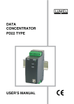
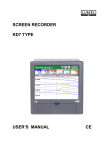
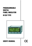
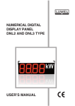
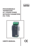
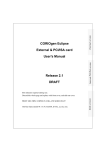
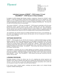
ELECTRONIC MULTI-TARIFF Three-phase WATT-HOUR METER WITH DIGITAL COMMUNICATION LS31 Type USER’S MANUAL CONTENTS 1. APPLICATION........................................................................................................................ 5 2. SET OF THE ENERGY WATT-HOUR METER...................................................................... 5 3. WATT-HOUR METER DESIGN.............................................................................................. 5 4. INSTALLATION...................................................................................................................... 7 5. DISPLAY OF INFORMATION.............................................................................................. 10 6. CHANGING THE WATT-HOUR METER CONFIGURATION.............................................. 12 7. ENERGY MEASUREMENT................................................................................................. 18 8. POWER REGISTERS.......................................................................................................... 19 9. CLOSURE OF THE ACCOUNTING PERIOD...................................................................... 19 10. AVAILABLE TARIFF GROUPS......................................................................................... 20 11. OPTICAL INTERFACE....................................................................................................... 22 12. RS-485 or RS-232 INTERFACE WITH MODBUS PROTOCOL........................................ 28 13. INTERNAL CONTROL CLOCK......................................................................................... 32 14. TECHNICAL DATA............................................................................................................ 32 15. ORDER CODES................................................................................................................. 34 16. MAINTENANCE AND WARRANTY................................................................................... 35 1. APPLICATION Multi-tariff three-phase watt-hour meters of LS31 type, resistant against external magnetic fields, are destined to be applied in dwelling-house, commercial and industrial buildings. Submitted to the interaction by strong external magnetic fields, they ensure the correct measurement of the electric energy consumption and the recording of the magnetic field presence together with transmitted information through the wire or wireless interface. This series of new LS31 electronic energy watt-hour meters enables the elimination of the effect of magnet use to falsify watt-hour meter indications. Watt-hour meters are equipped with the RS-485/MODBUS communication interface and the radio transmitter gives the possibility of a continuous monitoring, data archiving, visualisation and report. Thanks to the load measurement in each of L1, L2, L3 phases, they enable to analyse the network load asymmetry of network loads. These watt-hour meters can be connected to Ethernet computer networks, what is enabled through interface converters and protocols offered by Lumel. The carried out special Lumel-Control software developed in the Lumel’s Design Department, enables the creation of complex systems monitoring the energy consumption and other parameters. 2. SET OF THE WATT-HOUR METER The set consists of: - LS31 watt-hour meter..................................................................................................... 1 pc. - User’s manual................................................................................................................ 1 pc. - Warranty card................................................................................................................. 1 pc. When unpacking the instrument, please check whether the type and execution code on the data plate correspond to the order. 3. WATT-HOUR METER DESIGN The construction of the LS31 watt-hour meter is presented on the fig. 1 The watt-hour meter housing is made of lexan and ensures the servicing safety in the II protection degree. It consists of the base (1), terminal box (2), shield (3), and terminal case shield (4). The shield is fixed to the base by means of two internal catches and two screws (5) enabling the sealing by the manufacturer or the application of the verification mark. The cover of the terminal box is fixed to the terminal box by two screws (6) adapted to its sealing with lead by the energy power plant. At the lower part of the base, there are holes which together with the upper hanger (7) define the fixing points of the watt-hour meter to the cubicle or the niche destined to place the watt-hour meter. The shield has a transparent window enabling the readout of the display indications. Under the watt-hour meter shield, a 7-digit LCD (8) display with graphical symbols is placed. The standard equipment includes an impulse diode (9) with a defined imp/kWh time-constant and an optical link (10) enabling the readout of stored data by the watt-hour meter. The review and setting of watt-hour meter parameters is realised by the button (11) installed on the shield. The button is adapted to be sealed with lead. The function of parameter setting is accessible only after removing the leaden seal from the button. Fig. 1 Watt-hour meter design. 4. INSTALLATION 4.1. External dimensions and fixing way LS31 watt-hour meters are intended to be assembled on a wall. The box is equipped with screw terminals, with 9.4 mm of internal diameter (for 100 A a.c.), and 7.0 mm (for 60 A a.c.) for the connection to the power network, and auxiliary terminals enabling the connection of auxiliary circuits by a wire of 2.5 mm2 cross-section. Overall dimensions of the watt-hour meter are presented on the fig. 2. Fig. 2 Overall design of the LS31 watt-hour meter 4.2. Connection diagrams Three-phase watt-hour meter directly connected to a 4-wire network 3-phase 4-wire watt-hour meter directly connected to a 4-wire network, with impulse output 3-phase 4-wire watt-hour meter directly connected to 4-wire network, with an RS-485 communication interface and MODBUS protocol 3-phase 4-wire watt-hour meter for direct connection with RS-232 communication interface and MODBUS protocol. 3-phase 4-wire watt-hour meter directly connected ito a 4-wire network with radio SRD/IE/ inter- Fig. 3 External connection diagrams of the watt-hour meter 5. Displayed information The readout of following information is possible on the LCD display: Energy in the current zone, Current time (in format hour : min), Current date (in format year : month : day), Energy in zone T1, Energy in zone T2 (if occurs in the set tariff group), Energy in zone T3 (if occurs in the set tariff group), Energy in zone T4 (if occurs in the set tariff group), Total energy, Energy L1, Energy L2, Energy L3, Time of the accounting period closure (in format hour : minute), Date of the accounting period closure (in format year : month : day), Energy in zone T1, at the end of the previous accounting period, Energy in zone T2, at the end of the previous accounting period, Energy in zone T3, at the end of the previous accounting period, Energy in zone T4, at the end of the previous accounting period, Total energy, at the end of the previous accounting period, Symbol of the set tariff group. The beginning of parameter review, i.e. the transition from the energy displaying of the current zone, follows after pressing the push-button in the SCROLL position. Successive information are accessible sequentially. After 30 seconds from the last button pressure, the watt-hour meter returns to the normal working mode. Depending of the version and watt-hour meter configuration, the quantity of accessible information in the review mode can be lower. 5.1. Appearance of the LCD display Marking of the total energy value Symbol of the accounting period closure Symbols of tariffs Mode of the parameter setting Reference to the user’s manual Marking of active energy Units of the measured quantity Voltage markings L1, L2, L3 Marking of load (the arrows are whirling if energy is counted) Fig. 4 LCD display 10 units of the measured quantity 5.2. Displayed energy In the LS31 watt-hour meter directly connected, energy is displayed in kWh, with one decimal place. The watt-hour meter display has 7 digits. 5.3. LED impulse output The lighted LED red diode shows that energy is flowing. The diode is flickering proportionally to the energy flow. 5.4. Signalling of phase voltage presence Fig. 5 Indicators of the presence of phase voltages Markings L1, L2, L3 signal the presence or the lack of voltage in individual phases. The lack of a segment means the decrease of the voltage below 0.90 Un or the lack of voltage, whereas the visible marking means the presence of voltage in the given phase. 5.5 Signalling of active tariff zone Fig. 6 Tariff indicators The active tariff zone is indicated by one of the symbols, e.g. for the first tariff zone, the symbol T1 is displayed. For total energy of all zones , all accessible tariff symbols are displayed with the itotal marking of the sum . 5.6. Signalling of energy counting Fig. 7. Indicator of energy counting For signalling the energy counting, a marking composed of 3 arrows is accessible. When energy is counted, two arrows are shifting and that gives the effect of the marking rotation. If the watt-hour meter does not count energy, all arrows are visible (they do not rotate). The rotation speed of the marking is constant and does not depend on measured energy. 5.7. Signalling of data from the previous accounting period Fig. 8 Marking of the accounting period closure Parameters marked by this mark concern the closed accounting period. 11 5.8. Signalling of parameter review, programming parameters or interference by a magnetic field Fig. 9 Marking of parameter review When the user reviews parameters, programs watt-hour meter registers or is in the configuration change mode, the symbol presented on the fig.9 appears on the LCD display. The flickering symbol means interference by a strong magnetic field. If the watt-hour meter in under the interaction of this field, the marking is lighting on a continuous way. If the time of the field action was longer than 30 sec. and the watt-hour meter is not under its influence, then the marking is flickering till the time of erasing magnetic field interference through the optical link or by the button (after removing the leaden seal of the button). The information about the magnetic field interference is saving in the watt-hour meter memory. 5.9. Signalling of extra information Fig. 10. Marking of extra information The above symbol visible on the display, signals that the recording through the optical link is allowed. However, the flickering symbol signals the incorrect watt-hour meter operation. 6. CHANGING THE WATT-HOUR METER CONFIGURATION 6. 1. Button The watt-hour meter has a two-position button. The review of parameters is possible in the SCROLL position. In this position, the button can be sealed with lead. The suilable position of the button is set by means e.g. a wiew driwer. CAUTION: The button must be tismed in the nonpressed state. To transit into the SET position, one must remove the leaden seal, turn the button by 90° to the right. The table 1 presents functions of the button. SCROLL position SET position Functions of the button Button SCROLL Table 1 Working mode MEASUREMENT Function Review of parameters SCROLL SETUP Change of programmable parameter values SCROLL (> 2 sec.) SETUP Automatic incrementation of the parameter value SET (> 2 sec.) MEASUREMENT Entry in the mode of parameter configuration SET SETUP Selection of the parameter SET (> 2 sec.) SETUP Acceptation of the parameter group change The watt-hour meter transits from the mode of parameter review, or the mode of the parameter configuration, to the normal working mode after 30 sec. since the end of the user’s interference. 12 6.2. Way to change configuration parameters The scheme of the watt-hour meter main menu is presented on the fig. 11a. After pressing and holding down the SET button, during at least 2 sec., it is possible to programme parameters. The transition between parameters is carried out by means of the SET button. The description of parameters is included in the table 2. The return to the normal operation mode follows after revising all visible parameter groups or automatically after the laps of 30 sec. since the last button pressure. CAUTION: Some parameters or parametr settings can be invisible (inaccesible) depending on the watt-hour version and its current configuration. Fig. 11a Working modes of the LS31 watt-hour meter Fig. 11b Watt-hour meter work algorithm - Menu of optical interface 13 14 Fig. 11c Algorithm of the watt-hour meter work- tariff menu Fig. 11d Algorithm of the watt-hour meter work - menu of the real time clock Fig. 11e Algorithm of the watt-hour meter work - menu of accounting 15 Fig. 11f Algorithm of the Watt-hour meter work - menu of the serial Interface Fig. 11g Algorithm of watt-hour meter work - menu of magnet interference Fig. 11h Algorithm of watt-hour meter work - menu of power averaging 16 List of configuration parameters Main menu Parameter symbol opti set Parameter description Possibility of recording through the optical interface tr Selection of the tariff H1 H1 time for tariff groups G12, G12w, C12b, C12w, USEr H2 time for tariff groups G12, G12w, C12b, C12w, USEr H3 time for tariff groups G12, G12w, C12b, C12w, USEr H4 time for tariff groups G12, G12w, C12b, C12w, USEr Selection of tariff for the time interval since H1 till H2. Parameter accesible only in the USEr tariff group Selection of tariff for the time interval since H2 till H3. Parameter accesible only in the USEr tariff group Selection of tariff for the time interval since H3 till H4. Parameter accesible only in the USEr tariff group Selection of tariff for the time interval since H4 till H1. Parameter accesible only in the USEr tariff group Selection of tariff zone for Saturdays. Parameter accesible only for the USEr tariff group. The choice of the parameter „Cur” causes that the watt-hour meter counts the energy acc to parameter settings „rAn1... 4”. Selection of tariff zone for Sundays. Parameter accesible only for the USEr tariff group. The choice of the parameter „Cur” causes that the watt-hour meter counts the energy acc to parameter settings „rAn1... 4”. H2 H3 H4 ran1 tariff ran2 ran3 ran4 sat sun Hol Selection of tariff zone for Holidays. The choice of the parameter „Cur” causes that the watt-hour meter counts in the zone which results from the set tariff. Table 2 Range of parameter changes off: disabled on: enabled g11: tariff group G11 g12: tariff group G12 g12u: tariff group C12w C12a: tariff group C12a C12b: tariff group C12b C12u: tariff group C12w g13: tariff group G13 C22a: tariff group C22a C22b: tariff group C22b UsEr: User’s tariff 06:00...07:00 or optionally for USEr 13:00...4:00 or optionally for USEr 15:00...6:00 or optionally for USEr 22:00...23:00 or optionally for USEr t1: T1 zone t2: T2 zone t3: T3 zone t4: T4 zone t1: T1 zone t2: T2 zone t3: T3 zone t4: T4 zone t1: T1 zone t2: T2 zone t3: T3 zone t4: T4 zone t1: T1 zone t2: T2 zone t3: T3 zone t4: T4 zone Cur: as in chosen tariff group t1: T1 zone t2: T2 zone t3: T3 zone t4: T4 zone Cur: as in chosen tariff group t1: T1 zone t2: T2 zone t3: T3 zone t4: T4 zone Cur: as in chosen tariff group t1: T1 zone t2: T2 zone t3: T3 zone t4: T4 zone 17 List of configuration parameters Main menu clock Parameter symbol dy dn dd th tn atc eob eob Parameter description 2001...2035 Current year Current month 01...12 Current day 01...31 Current hour 00...23 00...59 Current minute Automatic change of the winter/summer off: turned off on: turned on Instant execution of the accounting period closure no: no yes: yes Day of automatic closure of the accounting period 01...28 th Hour of automatic closure of the accounting period 00...23 tn Minute of automatic closure of the accounting period 00...59 Working mode nodbus adr bd pouer Range of parameter changes dd rs Clear Table 2 Clr pa a8n1: ASCII 8N1 a7e1: ASCII 7E1 a7o1: ASCII 7O1 r8n2: RTU 8N2 r8e1: RTU 8E1 r8o1: RTU 8O1 r8n1: RTU 8N1 1... 247 Address Baud rate Clearing of the magnet interference Mode of power averaging 4.8: 4800 bit/sec 9.6: 9600 bit/sec 19.2: 19200 bit/sec no: no yes: yes 15.03: 15 min, subrange 3 min 15.05: 15 min, subrange 5 min 15.15: 15 min, subrange 15 min 30.06: 30 min, subrange 6 min 30.10: 30 min, subrange 10 min 30.30: 60 min, subrange 30 min 60.12: 60 min, subrange 12 min 60.20: 60 min, subrange 20 min 60.60: 60 min, subrange 60 min 7. ENERGY MEASUREMENT 7.1. Energy registration in tariffs The LS31 watt-hour meter counts energy in one of the tariffs in any time. When the register reaches its maximal value 999 999.9 kWh, it is automatically reset and the counting begins from zero. 18 7.2. Registration of total energy The recording of total energy consists on storage of the whole energy consumption in one register, independently of the tariff. When the register reaches its maximal value: 999 999.9 kWh, it is automatically reset and the counting begins from zero. 7.3. Energy measurement in each phase The measurement of energy in each phase consists on the storage of energy of each phase in separate registers. When the register reaches its maximal value - 999 999.9 kWh, it is automatically reset and the counting begins from zero 8. POWER REGISTERS 8.1. Averaged maximal power The measurement of averaged maximal power can be carried out in the period of 15, 30 or 60 minutes. The block mode or the shift mode is accessible to calculate the power index. For the shift mode, one can choose 5 or 3 sub-periods falling on the integration period. For the 15 minutes’ period, segments will be lasted 3 or 5 minutes. For the 30 minutes’ period, segments will be lasted 6 and 10 minutes and for 60 minutes’ period, segments will be lasted 12 or 20 minutes. The chosen number of sub-periods composes the integration period of power. After the first complete shift period comprising all sub-periods, the successive sub-period will be counted, and the first will not be taken in account. The watt-hour meter stores in the memory the maximal power for the current and the previous accounting period, and the time and date of its occurrence. 8.2. Cumulated power The cumulated power is the power register, increased by the value of the averaged maximal power at the end of the accounting period. 9. CLOSURE OF THE ACCOUNTING PERIOD The closure of the accounting period, ca be carried out manually or automatically. The manual closure of the accounting period can be carried out by means of the button (see table 2) or the optical link (by means of the optical probe and the software servicing the watt-hour meter). The automatic closure can follow automatically on the defined day of the month, in the set time. The configuration consists on the write of minute, hour and the day of the accounting period closure. The write of value 00 in the closure day causes the automatic switching off of the accounting period closure. At the moment of accounting period closure, energy values the total energy, and maximal power from all time zones will be memorized. The cumulated power is increased by the value of averaged maximal power. During the accounting period closure, the date and hour of the caried out operatory are stored. In case of lack of closure possibility, e.g. because of the supply lack, the closure process will be carried out after the supply voltage recovery. After each accounting period closure the counter is increased of one. Note: It is recommended to close the accounting period during the installation, in order to memorize the initial energy value already counted. If the accounting period closure was made on the day in which should occur the automatic closure, then the automatic closure will be cancelled on this day. 19 10. AVAILABLE TARIFF GROUPS 10.1. Tariff group G11 The energy is counted all the time in the zone 1. 10.2. Tariff group G12 Zone number Day zone (24 hours) 1. Day-time zone (T1) 2. Night-time zone (T2) Table 3 Season of the year (1 January - 31 December) H1 - H2 H3 - H4 H4 - H1 H2 - H3 Markings: H1: 600 ÷ 700 H2: 1300 ÷ 1400 H3: 1500 ÷ 1600 H4: 2200 ÷ 2300 Holidays are included to the zone depended on the Hol parameter setting in tAriFF 10.3. Tariff group G12w Zone number Day zone (24 hours) 1. Day-time zone (T1) 2. Night-time zone (T2) Table 4 Season of the year (1 January - 31 December) H1 - H2 H3 - H4 H4 - H1 H2 - H3 Markings: H1: 600 ÷ 700 H2: 1300 ÷ 1400 H3: 1500 ÷ 1600 H4: 2200 ÷ 2300 Holidays are included to the zone depended on the Hol parameter setting in tAriFF Saturdays and Sundays are included during the all day in the second zone - night zone. 10.4. Tariff group G13 Zone number Day zone (24 hours) 1. 2. Ante-meridian peak (T1) Post-meridian peak (T2) Table 5 Season of the year Summer Winter (1 April - 30 September) (1 October - 31 March) 700 - 1300 700 - 1300 1900 - 2200 1600 - 2100 1300 - 1900 1300 - 1600 3. Remaining hours of the day (T3) 2200 - 700 2100 - 700 Day-offs according to the law, Saturdays and Sundays are counted during the day (24 hours) in the third zone as remaining hours of the day. 20 10.5. Tarif group C12a Zone number Day zone (24 hours) 1. 2. Table 6 Season of the year (1 April - 30 September) Winter (1 October - 31 March) Peak zone (T1) 800 - 1100 2000 - 2100 800 - 1100 1700 - 2100 Exstra-peak zone (T2) 1100 - 2000 2100 - 800 1100 - 1700 2100 - 800 Summer Holidays are included to the zone depended on the Hol parameter setting in tAriFF 10.6. Tarif group C12b Table 7 Zone number Day zone (24 hours) Season of the year (1 January - 31 December) 1. Day-time zone (T1) H1 - H2 H3 - H4 2. Night-time zone (T2) H4 - H1 H2 - H3 Markings: H1: 600 ÷ 700 H2: 1300 ÷ 1400 H3: 1500 ÷ 1600 H4: 2200 ÷ 2300 Holidays are included to the zone depended on the Hol parameter setting in tAriFF 10.7. Tarif group C12w Table 8 Zone number Day zone (24 hours) Season of the year (1 January - 31 December) 1. Day-time zone (T1) H1 - H2 H3 - H4 2. Night-time zone (T2) H4 - H1 H2 - H3 Markings: H1: 600 ÷ 700 H2: 1300 ÷ 1400 H3: 1500 ÷ 1600 H4: 2200 ÷ 2300 Holidays are included to the zone depended on the Hol parameter setting in TariFF Saturdays and Sundays are counted during the day (24 hours) in the second zone - night zone. 21 10.8. Tariff group C22a Zone number Day zone (24 hours) 1. Peak zone (T1) 2. Extra-peak zone (T2) Table 9 Season of the year I, II, XI, XII 800 - 1100 1600 - 2100 III, X 800 - 1100 1800 - 2100 IV, IX 800 - 1100 1900 - 2100 2100 - 800 1100 - 1600 2100 - 800 1100 - 1800 2100 - 800 1100 - 1900 V, VI, VII, VIII 800 - 1100 2000 - 2100 2100 - 800 1100 - 2000 Holidays are included to the zone depended on the Hol parameter setting in tAriFF 10.9. Tariff group C22b Table 10 Zone number Day zone (24 hours) 1. Peak zone (T1) Season of the year (1 January - 31 December) 600 - 2100 2. Extra-peak zone (T2) 2100 - 600 Holidays are included to the zone depended on the Hol parameter setting in tAriFF 10.10. List of holidays (day-free of work) Foloving holidays being day-offs statutory: święta stałe: 1st January (New Year), 1st May (international holiday), 3rd May (National Polish holiday of the 3rd May), 15th August (Feast of the Assumption), 1st November (All Sainto day), 11th November (National Independence - holiday in Poland), 25th December (First day of Christmas), 26th December (Second day of Christmas). mobile holidays: first and second day of Easter, Corpus Christy. 11. OPTICAL INTERFACE Set of optical link parameters of the LS31 watt-hour meter. compliance with standard EN 62065-21 manufacturer’s identifier LML Speed identifier 4 Watt-hour meter identifier LS31-LUMEL Transmission protocol Mode C of transmission Transmission initialization 300 bauds accessible baud rate 300, 600, 1200, 2400, 4800, bit/s character format 7E1 recording locking by the button secured by the leaden seal 22 The optical interface in the watt-hour meter enables the realization of following functions: - data readout from the watt-hour meter, - write of selected parameters into the watt-hour meter, - closure of the accounting period. The parameter write and/or closure of the accounting period through the optical interface is possible after the rupture of the the button leader seal. To unlock or lock the write, one must: - press the SET button for a time longer than 2 sec, - pressing the SET button transit to the „opti” menu, - by means of the SCROLL button unlock the „sEt on” notation or lock the „sEt off” notation, - pressing the SET button for a time longer than 2 sec, accept the change, - pressing the SET button, exit from the main menu configuration. The write locking follows automatically after a 5 minutes’ lack of communication through the optical link. 11. 1 Registers of LS31 watt-hour meter The table 11 presents the set of watt-hour meter registers together with identifiers and example of contents in case of data readout. NOTE: Depending of the watt-hour meter version and configuration, the number of registers accessible for readout can be smaller. Registers of watt-hour meters accessible through the optical interface Identifier (ASCII characters) Format ASCII characters 28 12:34:56 29 25-11-02 0.0 AbcDeFgHiJ 0.0.1 02110001 0.8.1 000123.4*kWh 0.8.2 000423.4*kWh 0.8.3 000623.4*kWh 0.8.4 000723.4*kWh 0.8.0 001323.4*kWh 0.8.0.1 000543.1*kWh 0.8.0.2 000654.4*kWh 0.8.0.3 000765.4*kWh 0.6.0 10:23 20-11-02; 99.2*kW 70. 10:23 20-11-02 0.8.1*00 000123.4*kWh 0.8.2*00 000423.4*kWh Table 11 Parameter Current time (hh:mm:ss) Current date (dd-mm-yy) User’s identifier Serial number Energy in zone T1 Energy in zone T2 Energy in zone T3 Energy in zone T4 Total energy of all zones Total energy of phase one Total energy of phase two Total energy of phase three Time and date of maximal power occurrence, 15' or 60' and its value Time and date of closing the accounting period Energy in zone T1 at the end of the previous accounting period Energy in zone T2 at the end of the previous accounting period 23 Table 11 Identifier (ASCII characters) Format ASCII characters Parameter 0.8.3*00 000623.4*kWh 0.8.4*00 000723.4*kWh 0.8.0*00 001323.4*kWh 0.6.0*00 10:23 19-11-02; 90.2*kW 0.6 6344.7*kW 0.1. 22352 Energy in zone T3 at the end of the previous accounting period Energy in zone T4 at the end of the previous accounting period Total energy at the end of the previous accounting period Time and period of 15' or 60' maximal power occurrence in the previous accounting period and its value Cumulated power (maks. „65535”) Counter of accounting period closure (maks. „65535”) Watt-hour meter status: 54. 010301 FF 01101000 00011000 0.43 7 1st character - Signaling of voltage in phase L1 (‘0’-lack; ‘1’-exists) 2nd character - Signalling of voltage in phase L2 (‘0’-lack; ‘1’-exists) 3rd character- Signalling of voltage in phase L3 (‘0’-lack; ‘1’-exists) 4th character - Current time zone: ‘1’ - zone 1 ‘2’ - zone 2 ‘3’ - zone 3 ‘4’ - zone 4 5 th character - reserved (always ‘0’) 6 th character - signalling of interference by a magnetic field (‘0’, ‘1’) Register of watt-hour meter errors (see table 12) (‘0’ or ‘1’) Time of power averaging and number of sub-periods: ‘0’ - 15 min, sub-period 3 min ‘1’ - 15 min, sub-period 5 min ‘2’ - 15 min, sub-period 15 min ‘3’ - 30 min, sub-period 6 min ‘4’ - 30 min, sub-period 10 min ‘5’ - 30 min, sub-period 30 min ‘6’ - 60 min, sub-period 12 min ‘7’ - 60 min, sub-period 20 min ‘8’ - 60 min, sub-period 60 min 50. 17;13:55 Day and time in which the accounting period is closed (day ‘00’ - automatyczne zamykanie wyłączone; dzień ‘01’...‘28’; godzina ‘00’...‘23’; minuta ‘00’...‘59’) 51. 05 Kind of tariff group: ‘00’ - G11 ‘01’ - G12 ‘02’ - G12w ‘03’ - C12a 24 cd. Tablica 11 Identifier (ASCII characters) Format ASCII characters 51. 05 51.1 07:20; 10:12; 22:30; 23:30 1010111 51.2 Parameter ‘04’ - C12b ‘05’ - C12w ‘06’ - G13 ‘07’ - C22a ‘08’ - C22b ‘09’ - USEr (user’s tariff) ‘10’ - control by the external clock Variable hours for tariffs: G12, G12w, C12b, C12w, User Time zones for tariff hours, Saturdays, Sundays and holidays (tylko dla taryfy USEr) 1 st character - Zone for hour interval since H1 till H2 2 nd character - Zone for hour interval since H2 till H3 3 rd character - Zone for hour interval since H3 till H4 4 th character - Zone for hour interval since H4 till H1 Meaning of 1... 4 character: ‘0’ - T1 zone ‘1’ - T2 zone ‘2’ - T3 zone ‘3’ - T4 zone 5 th character - zone for Sathurdays (only for USEr tariff) 6 th character - zone for Sundays (only for USEr tariff) 7 th character - zone for holidays Meaning of 5... 7 character: ‘0’ - without time zone ‘1’ - T1 zone ‘2’ - T2 zone ‘3’ - T3 zone ‘4’ - T4 zone In case when the ‘0’ is chosen, time zones are defined acc. to the selected tariff group (see the description of tariff zones in table 2). 52. 22112 Configuration of the serial link (mode, address, baud rate): 1st character - mode ‘1’ - ASCII 8N1 ‘2’ - ASCII 7E1 ‘3’ - ASCII 7O1 ‘4’ - RTU 8N2 ‘5’ - RTU 8E1 ‘6’ - RTU 8O1 ‘7’ - RTU 8N1 2, 3, 4 character - address („001”...”247”) 5 th character - baud rate ‘0’ - 4800 baud ‘1’ - 9600 baud ‘2’ - 19200 baud 25 Table 11 Identifier (ASCII characters) 53. Format ASCII characters 6.4 55. 1 76.1 10:12 25-11-05; 76.2 000000327 78 00003 Parameter Number of the program version Automatic change of the winter/summer time. ‘0’ - disabled ‘1’ - enabled Hour and date of the first beginning of interference by a strong magnetic field. Duration of interference by a strong magnetic field (sec) Number of interference by a strong magnetic field cleared registers. FF register description - watt-hout meter errors Character number 0 1 2 3 4 5 6 7 8 9 10-14 15 26 Table 12 Description Invalid contents was found - energy in the zone T1 Invalid contents was found - energy in the zone T2 Invalid contents was found - energy in the zone T3 Invalid contents was found - energy in the zone T4 Invalid contents was found - total energy Invalid contents was found - energy in zone T1 in the previous accounting period Invalid contents was found - energy in zone T2 in the previous accounting period Invalid contents was found - energy in zone T3 in the previous accounting period Invalid contents was found - energy in zone T4 in the previous accounting period Invalid contents was found - total energy in the previous accounting period Not used Incorrect value of the error register 11.2. Watt-hour meter registers in the programming and readout mode Watt-hour meter registers are accessible in the programming and readout mode through the optical interface Identifier (ASCII characters) Format ASCII characters Parameter Table 13 Function T 12:34:56; Current time and date 25-11-02 A 1 Automatic change of the winter/summer time I AbcDeFgHiJ User’s identification number N 02110001 Serial manufacturer’s D 7 Time of averaging power and number of sub-periods: (as in table 11) E 17;13:55 Day and time in which the accounting period is closed (day ‘00’ - automatic closure is disabled; day ‘01’... ‘28’; hour ‘00’... ‘23’ : minute ‘00’... ‘59’) G 05 Kind of tariff group acc. to the table 11 H 07:20; 10:12; Variable hours for tariffs G12, G12w, C12b, C12w 22:30; 23:30 USEr C 22112 Configuration of the serial link: mode, address, baud rate, acc. to the table 11 R 1 Clearing of registers related to interference with a strong magnetic field Z 1010111 Markings: Selection of time zone for tariff hours, Saturdays, Sundays and holidays. (only for USEr tariff). R/W R/W R/W R R/W R/W R/W R/W R/W R/W R/W 1 st character - selection of zone for hour interval since H1 till H2 2 nd character - selection of zone for hour interval since H2 till H3 3 rd character - selection of zone for hour interval since H3 till H4 4 th character - selection of zone for hour interval since H4 till H1 Meaning of 1... 4 character: 0 - T1 zone 1 - T2 zone 2 - T3 zone 3 - T4 zone 5 th character - zone for Sathurdays (only for USEr tariff) 6 th character - zone for Sundays (only for USEr tariff) 7 th character - zone for holidays Meaning of 5... 7 character: 0 - as for the chosen tariff group 1 - T1 zone 2 - T2 zone 3 - T3 zone 4 - T4 zone In case when the ‘0’ is chosen, time zones are defined acc. to the selected tariff group. (see the description of tariff zones in table 2). R - only readout R/W - readout and write NOTE: In case of watt-hour meter configuration, when the given parameter is not used, the identification error code of the data ‘ERROR (05)’ is returned at the write or readout. 27 12. RS-485 or RS-232 INTERFACE with MODBUS protocol Set of parameters of the LS31 watt-hour meter serial interface: identifier 0x9F watt-hour meter address 1...247 baud rate 4800, 9600, 19200 bit/s, working mode ASCII, RTU, information unit ASCII: 8N1, 7E1, 7O1; RTU: 8N2, 8E1, 8O1, 8N1, maximal response time 600 ms. implemented functions 03 - readout of n registers 17 - identification of the slave device Factory settings: address 1, baud rate 9600 bauds, RTU 8N2 mode Register map of the LS31 watt-hour meter In the LS31 watt-hour meter, data are placed in 16-bit registers. Process variables and parameters of the watt-hour meter are placed in the address area of registers in a way depending on the type of the variable value. Bits in the 16-bit register are numbered from the younger to the older (b0-b15). Table with 16-bit registers of the watt-hour meter Register Parameter number Description Range 0... 65535 Watt-hour meter status Description in table 15 4000 word 4001 word 2001... 2035 Current year 4002 word 101... 1231 4003 word 0... 2359 Table 14 Current date in format: month * 100 + day Bieżący czas w formacie: godzina * 100 + minuta 4004 MS word 0501000... Serial number 4005 LS word 35129999 4006 word 0x00...0xEE User identifier (1 and 2 character) 4007 word 0x00...0xEE User identifier (3 and 4 character) 4008 word 0x00...0xEE User identifier (5 and 6 character) 4009 word 0x00...0xEE User identifier (7 and 8 character) 4010 word 0x00...0xEE User identifier (9 and 10 character) 4011 word) 4012 LS word 4013 MS word 4014 LS word 4015 MS word 4016 LS word 4017 MS word 4018 LS word 28 0... 99999999 Active energy in zone T1 (kWhx100) 0... 99999999 Active energy in zone T2 (kWhx100) 0... 99999999 Active energy in zone T3 (kWhx100) 0... 99999999 Active energy in zone T4 (kWhx100) Table with 16-bit registers of the watt-hour meter Register Parameter number 4019 MS word 4020 LS word 4021 MS word 4022 LS word 4023 MS word 4024 LS word 4025 MS word 4026 LS word 4027 MS word 4028 LS word 4029 MS wordR 4030 LS word 4031 MS word 4032 LS word 4033 MS word 4034 LS word 4035 MS word 4036 LS word Range Table 14 Description 0... 99999999 Total active energy (kWhx100) 0... 99999999 Total energy of phase L1 (kWhx100) 0... 99999999 Total energy of phase L2 (kWhx100) 0... 99999999 Total energy of phase L3 (kWhx100) 0... 99999999 Active energy in zone T1 at the end of the previous accounting period (kWhx100) 0... 99999999 Active energy in zone T2 at the end of the previous accounting period (kWhx100) 0... 99999999 Active energy in zone T3 at the end of the previous accounting period (kWhx100) 0... 99999999 Active energy in zone T4 at the end of the previous accounting period (kWhx100) 0... 99999999 Total active energy at the end of the previous accounting period (kWhx100) 4037 word 4038 word 2001... 2035 Year of accouting period closures 0... 65535 Counter of accouting period closures 4039 4040 4041 4042 4043 4044 4045 4046 4047 4048 word word word word word word word word word word 101... 1231 0... 2359 0... 700 2001... 2035 101... 1231 0... 2359 0... 455 2001... 2035 101... 1231 0... 2359 4049 word 0... 65535 Date of accouting period closure in format: month * 100 + day Time of accouting period closure in format: hour * 100 + minute Highest value of averaged power (kW x 10) Year in which the highest value of averaged power has occured Date in which the highest value of averaged power has occured, in format: month * 100 + day Time in which the highest value of averaged power has occured, in format: hour * 100 + minute Highest value of averaged power in the previous accounting period (kW x 10) Year in which the highest value of averaged power has occured in the previous accounting period Date in which the highest value of averaged power has occured in the previous accounting period, in format: month * 100 + day Time in which the highest value of averaged power has occured in the previous accounting period, in format: hour * 100 + minute Cumulated power (kW x 10) 29 Table with 16-bit registers of the watt-hour meter Register Parameter number Range Table 14 Description 4050 4051 word word 0... 8 0... 2359 Way of power averaging: 0 - 15 min, sub-period 3 min 1 - 15 min, sub-period 5 min 2 - 15 min, sub-period 15 min 3 - 30 min, sub-period 6 min 4 - 30 min, sub-period 10 min 5 - 30 min, sub-period 30 min 6 - 60 min, sub-period 12 min 7 - 60 min, sub-period 20 min 8 - 60 min, sub-period 60 min Time of the automatic closure of the accounting period in the format: hour * 100 + minute 4052 4053 word word 0... 28 0... 32000 Day of the automatic closure of the accounting period (0 - automatic closure disabled) Impulse output constant (imp/kWh) 4054 word 0... 9 Tariff group: 0 - G11 1 - G12 2 - G12w 3 - C12a 4 - C12b 5 - C12w 6 - G13 7 - C22a 8 - C22b 9 - USEr (user’s tariff) Nr of the program version (x10) 4055 word 10... X 4056 word 0... 65535 4057 word 2000... 2035 Year of the first start of interference period by a strong magnetic field 4058 word 101... 1231 Month and day of the start of the first interference period by a strong magnetic field 4059 word 0... 2359 Time of the start of the first interference period by a strong magnetic field (sec) 0... (232-1) Duration of interference by a strong magnetic field [sek] 4060 MS word 4061 LS word 4062 word ... 4063 word 0... 65535 30 Register of watt-hour meter errors description in the table 16. Reserved Number of delation executions of interference by a strong magnetic field Meaning of bits in the Status register (register 4000) Bit Table 15 Description 0 Voltage signalling in the phase L1 0 - voltage below 0.9 Un 1 - voltage over 0.9 Un 1 Voltage signalling in the phase L2 0 - voltage below 0.9 Un 1 - voltage over 0.9 Un 2 Voltage signalling in the phase C 0 - voltage below 0.9 Un 1 - voltage over 0.9 Un 3 - 5 Current time zone: Bits: 5 4 3 0 0 1 - zone 1 0 1 0 - zone 2 0 1 1 - zone 3 1 0 0 - zone 4 6 - 7 Decimal place for power: Bits: 7 6 0 0 - without decimal places 0 1 - 1 decimal place 1 0 - 2 decimal place 8 - 9 Decimal place for energy: Bits: 9 8 0 0 - without decimal places 0 1 - 1 decimal place 1 0 - 2 decimal place 10 - 11 Prefix of unit for energy and power: Bits:11 10 0 0 - lack 0 1-k 1 0-M 12 Interference by a strong magnetic field: 0 - lack 1 - exist 13 - 14 Not used 15 Error - one must check the register of errors 0 - without error 1 - error exists 31 Meaning of bits in the register of errors (register 4056) Bit 0 Erroneous content was found - energy in zone T1 1 Erroneous content was found - energy in zone T2 2 Erroneous content was found - energy in zone T3 3 Erroneous content was found - energy in zone T4 4 Erroneous content was found - total energy Table 16 Description 5 Erroneous content was found - energy in zone T1 in the previous accounting period 6 Erroneous content was found - energy in zone T2 in the previous accounting period 7 Erroneous content was found - energy in zone T3 in the previous accounting period 8 Erroneous content was found - energy in zone T4 in the previous accounting period 9 Erroneous content was found - total energy in the previous accounting period 10 - 14 Not used 15 Incorrect value of the register of errors 13. INTERNAL CONTROL CLOCK The watt-hour meter comprises an astronomical clock supported by a battery. The current time is counted in the 24 hour format. The clock has the function of automatic change of the winter time into the summer time and inversely. The change of time from the winter time into summer time is carried out in the night from Saturday to Sunday. In the last Sunday of March, the clock is reset from 2:00 till 3:00. The change of time from the summer time into the winter time is carried out in the night from Saturday to Sunday, in the last Sunday of October, the clock is reset from 3:00 till 2:00. If the user sets the current time between 2:00 and 3:00 in the last Sunday of October, the clocks accepts the summer time. The function of automatic change of time can be disabled. 14. TECHNICAL DATA Kinds of network 4-wire Watt-hour meter connection way direct Reference voltage Un 3 230/400 V Basic current Ib 5 or 10 A Maximal current Imax 40, 60 or 100 A Accuracy class 1 or 2 32 Working temperature range - 25...+55°C Storage temperature - 30...+85°C Readout field special LCD display Communication interfaces: - optical interface acc. to EN 62056-21, - RS-485, MODBUS protocol, - RS-232, MODBUS protocol, - Radio module: -transmission frequency - band width - emission power - baud rate - modulation 433.92 MHz 19.04 kHz below 10 mW 10 bit/s FSK Output of energy pulses output of OC type, passive acc. to EN 62053-31 Pulse time-constant of the OC type output 1000 imp./kWh Pulse time-constant of the LED diode 1000 imp./kWh Number of tariffs 1... 4 Accessible tariffs G11, G12, G12w, G13, C12a, C12b, C12w, C22a, C22b, USEr Power consumption: - in the voltage circuit - in the current circuit 3.3 VA/phase 0.02 VA Starting current: 0.004 Ib Detection level of the voltage presence 0.9 Un Resistance against external permanent magnetic field 640 kA/m Resistance against voltage surges 4 kV Watt-hour meter reaction against phase decays: - preservation of data and watt-hour meter state after a 3-phase decay in the non-volatile FRAM memory, - storage life: min. 15 years, - work continuation when a 1 or 2-phase decay occurs. Battery life min. 10 years Clock accuracy ± 3s/day Standards fulfilled by the watt-hour meter EN 62052-11, EN 62053-2 Approved by the Central Measurement Office PLT 0648 Protection degree ensured by the housing IP 54 External dimensions (H W D) 328 176 65 mm Weight ca. 2.0 kg 33 15. ORDERING CODES LS31 electronic 3-phase watt-hour meter for direct measurements with an LCD display and a optical interface. Electronic watt-hour meter LS31 X X XX X X Basic and maximal current: 5 (40) A . ............................................... 1 5 (60) A . ............................................... 2 10 (100) A . ........................................... 3 5 (100) A 1) . ........................................... 4 on order . ...............................................X Input voltage: 3 230/400 V ...............................................1 on order . ........................................................X Communication interface: optical port ............................................................00 optical port + output of O/C type ............................01 optical port + RS-485, Modbus protocol ...............02 optical port + RS-232, Modbus protocol ................04 optical port + SRD radio module (1E) ....................20 on order . .............................................................. XX Accuracy class: 1 ...................................................................................... 1 2 ...................................................................................... 2 Acceptance tests: without legalisation . ................................................................ 8 with a legalisation certificate .................................................. 7 acc. customer’s agreement1) ...................................................X 1) - Custom-made version, must be agreed with the manufacturer. ORDERING EXAMPLE: The code: LS31 3 1 02 7 means: LS31 - watt-hour meter of LS31 type 3 - basic and maximal current: 10 (100) A 1 - input voltage: 3 x 230/400 V 02 - with an optical port + RS-485, MODBUS protocol, 1 - class 1 of accuracy, 7 - with a legalisation certificate. 34 16. MAINTENANCE AND WARRANTY The LS31 watt-hour meter does not require any periodical maintenance. In case of some incorrect operations: 1. After the dispatch date and within the period stated in the warranty card One should return the instrument to the Manufacturer’s Quality Inspection Dept. If the instrument has been used in compliance with the instructions, the Manufacturer warrants to repair it free of charge. The disassembling of the housing causes the cancellation of the granted warranty. 2. After the warranty period: One should send the instrument to repair it in an authorized service workshop. Spare parts are available for the period of five years from the date of purchase. Our policy is one of continuous improvement and we reserve the right to make changes in design and specifications of any products as engineering advances or necessity requires and revise the above specifications without notice. 35 LS31-09A LUMEL S.A. ul. Słubicka 1, 65-127 Zielona Góra, Poland Tel.: (48-68) 45 75 100 (exchange) Fax: (48-68) 45 75 508 e-mail:[email protected] http://www.lumel.com.pl Export Department: Tel.: (48-68) 45 75 139/305/321/386 Fax: (48-68) 32 54 091 e-mail: [email protected]