1
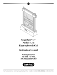
Sub-Cell GT
Agarose Gel
Electrophoresis
Systems
®
Instruction Manual
Catalog Numbers
170-4401 to 170-4406
170-4481 to 170-4486
For Technical Service Call Your Local Bio-Rad Office or in the U.S. Call 1-800-4BIORAD (1-800-424-6723)
Warranty
Bio-Rad Laboratories warrants the Sub-Cell GT, Wide Mini-Sub® cell GT, and Mini-Sub cell GT
electrophoresis systems against defects in materials and workmanship for 1 year. If any defects occur
in the instrument during this warranty period, Bio-Rad Laboratories will repair or replace the defective
parts free. The following defects, however, are specifically excluded:
1. Defects caused by improper operation.
2. Repair or modification done by anyone other than Bio-Rad Laboratories
or an authorized agent.
3. Use of fittings or other spare parts supplied by anyone other than
Bio-Rad Laboratories.
4. Damage caused by accident or misuse.
5. Damage caused by disaster.
6. Corrosion due to use of improper solvent or sample.
This warranty does not apply to parts listed below:
1. Platinum Electrode Wires
To insure the best performance from the Sub-Cell GT electrophoresis systems, become fully
acquainted with these operating instructions before use. Bio-Rad recommends that you first read these
instructions carefully. Assemble and disassemble the unit completely without casting a gel. After these
preliminary steps, you should be ready to cast and run a gel.
Bio-Rad also recommends that all Sub-Cell GT system components and accessories be inspected for
damage, cleaned as recommended in this manual, and rinsed thoroughly with distilled water before use.
Record the following for your records:
Model
Catalog No.
Date of Delivery
Warranty Period
Serial No.
Invoice No.
Purchase Order No.
For any inquiry or request for repair service, contact Bio-Rad Laboratories after confirming the
model and serial number of your instrument.
Table of Contents
Page
Section 1
General Information....................................................................................1
1.1
1.2
1.3
1.4
Introduction ................................................................................................................1
Safety ..........................................................................................................................1
System Components...................................................................................................2
Specifications .............................................................................................................4
Section 2
Operating Instructions ................................................................................4
2.1
2.2
2.3
2.4
2.5
DNA Gel Preparation.................................................................................................4
Casting Agarose Gels.................................................................................................6
Electrophoresis ...........................................................................................................8
Nucleic Acid Staining and Visualization...................................................................9
Note on Blotting .......................................................................................................10
Section 3
Gel and Electrophoresis Reagent Preparation .......................................10
Section 4
Care and Maintenance...............................................................................11
4.1
4.2
4.3
4.4
4.5
Cleaning Sub-Cell GT Components ........................................................................12
Compatible Cleaning Agents ...................................................................................12
Maintenance Schedule .............................................................................................12
Electrode Replacement.............................................................................................13
RNase Decontamination ..........................................................................................14
Section 5
Troubleshooting..........................................................................................14
Section 6
Product Information..................................................................................15
6.1
6.2
6.3
Sub-Cell GT Systems...............................................................................................15
Sub-Cell GT System Accessories ............................................................................16
Related Bio-Rad Products........................................................................................18
Section 7
References ...................................................................................................21
Section 1
General Information
1.1 Introduction
The Sub-Cell GT instruments (basic Sub-Cell GT cell, Wide Mini-Sub® cell GT, and MiniSub cell GT) comprise a comprehensive and flexible gel electrophoresis system that effectively separates nucleic acids using submerged agarose gels. Submarine agarose gels are easy to
cast and readily dissipate heat. These gels allow sample underlaying and prevent electrical field discontinuities caused by wicks or sample well dehydration. Agarose gels are ideal for the separation of
DNA restriction digestions, Polymerase Chain Reaction (PCR*)-amplified fragments, and genomic
DNA and RNA prior to Southern or northern blotting. If operated correctly, agarose gel submarine
electrophoresis can effectively separate nucleic acids from 20 base pairs to 20 kilobase pairs in length.
The Sub-Cell GT systems are designed for years of reproducible and rigorous use. These
rugged systems incorporate many features that make casting and running agarose gels simple
and efficient. The gel caster provides tape-free gel casting in trays. Gels can also be cast in the
GT bases using specially designed wedge gates. Replaceable electrode cassettes provide a
simple way to replace electrode wires. A comprehensive assortment of base and tray sizes,
including a variety of preparative, analytical, and multichannel pipet compatible combs, makes
these systems ideal for any agarose gel application.
Note: This manual contains instructions for the Sub-Cell GT electrophoresis systems only.
Prior to the release of the Sub-Cell GT systems, Bio-Rad supplied similar agarose gel electrophoresis cells: the original Sub-Cell DNA electrophoresis cell, Wide Mini-Sub cell, and MiniSub cell systems. This manual does not provide information on these earlier versions. Contact
your local Bio-Rad representative for information concerning the original Sub-Cell systems.
Definition of Symbols
!
Caution, risk of electrical shock
1.2 Safety
Caution (refer to accompanying documents)
!
The Sub-Cell GT electrophoresis systems are designed for maximum user safety. The buffer
chambers are made of 3/16 inch (.476 cm) thick injection-molded acrylic to create a leak-free
electrophoresis environment. The safety lids surround the buffer chamber to protect the user from
exposure to electrical currents. All Sub-Cell GT systems were designed for indoor use only.
Before use, inspect the GT base for cracks or chips, which may allow the buffer to leak
from the base and cause a potential electrical hazard. Additionally, inspect all electrical cables,
banana jacks, and plugs for loose connections, cracks, breaks, or corrosion. Do not use any part
that is cracked, charred, or corroded. These parts may also cause a potential electrical hazard.
Contact your local Bio-Rad representative before using a part that may be considered hazardous.
During electrophoresis, inspect the base and workbench for any signs of buffer leakage.
If leaking buffer is detected, disconnect the power to the cell immediately and contact your
local Bio-Rad representative.
Power to Sub-Cell GT units is supplied by an external DC voltage power supply. This
power supply must be ground isolated in such a way that the DC voltage output floats with
1
respect to ground. All of Bio-Rad’s power supplies meet this important safety requirement.
The recommended power supply for this apparatus is the PowerPac 300 power supply. The
PowerPac 300 power supply contains safety features such as no load, overload, rapid resistance change, and ground leak detection capabilities. The maximum specified operating parameters for the Sub-Cell GT systems are given in Table 1.1.
Table 1.1 Sub-Cell GT systems operating parameters
Maximum voltage limit
Maximum power limit
Maximum Buffer temperature
Sub-Cell
GT Cell
Wide Mini-Sub
Cell GT
Mini-Sub
Cell GT
200 VDC
40 Watts
40 ˚C
150 VDC
45 Watts
40 ˚C
150 VDC
10 Watts
40 ˚C
Current to the cell, provided from the external power supply, enters the unit through the
lid assembly, providing a safety interlock. Current to the cell is broken when the lid is removed.
Do not attempt to circumvent this safety interlock, and always turn the power supply off
before removing the lid or when working with the cell.
Important: These Bio-Rad instruments are certified to meet IEC 1010-1** safety standards. IEC-certified products are safe to use when operated in accordance with the instruction
manual. This instrument should not be modified in any way. Alteration of this instrument will:
•
•
•
Void the manufacturer’s warranty
Void the IEC 1010-1 safety certification
Create a potential safety hazard
IEC 1010-1 certification applies to equipment designed to be safe between the operating
temperatures of 4 °C and 40 °C and altitudes up to 2,000 meters. Instruments are also safe at a maximum relative humidity of 80% for temperatures up to 31 °C decreasing linearly to
50 % at 40 °C. Bio-Rad is not responsible for any injury or damage caused by the use of this instrument for purposes other than those for which it is intended, or by modifications of the instrument
not performed by Bio-Rad or an authorized agent. No user-serviceable parts are contained in this
apparatus. To insure electrical safety, do not attempt to service this apparatus.
1.3 System Components
Each of the Sub-Cell GT systems comes with the components listed in Table 1.2 (see
Figure 1.1 for part description). Check your instrument to be sure all items are present. Note
any damage to the unit which may have occurred during shipping. Notify Bio-Rad
Laboratories if any items are missing or damaged.
Table 1.2 Sub-Cell GT System Components
Item
GT Base (buffer chamber)
Gel Casting Gates
Safety Lid and Cables
UVTP Gel Tray
Fixed Position Comb
Leveling Bubble
Gel Caster (optional)
Instruction Manual
Sub-Cell GT
System
Quantity
Wide Mini-Sub Cell
GT System
Quantity
1
1
2
2
1
1
1
1
2
2
(15 well, 1.5 mm thick) (15 well, 1.5 mm thick)
(20 well, 1.5 mm thick) (20 well, 1.5 mm thick)
1
1
1
1
1
1
2
Mini-Sub Cell
GT System
Quantity
1
2
1
1
2
(8 well, 1.5 mm thick)
(15 well, 1.5 mm thick)
1
1
1
Safety lid
Electrical cables
Fixed height
comb
Comb
slots
Banana plug/
Electrode wire
assembly
Fluorescent
ruler
UVTP gel tray
Electrical leads
Gel casting gates
GT Base
Safety Lid removal peg
Leveling feet
Fixed height
comb
Fluorescent
ruler
Leveling feet
UVTP gel tray
Cam lever
Gel caster
Leveling bubble
Leveling feet
Fig.1.1. Sub-Cell GT parts.
3
1.4 Specifications
Sub-Cell GT Wide Mini-Sub Cell Mini-Sub Cell
System
GT System
GT System
GT base footprint (L x W x H)
GT base buffer volume✝
GT base gel size
Gel tray sizes
42 x 19.5 x 10 cm
1,500–2,000 ml
15 x 15 cm
15 x 10 cm
15 x 15 cm
15 x 20 cm
15 x 25 cm
26 x 20 x 7.5 cm
650–900 ml
15 x 7 cm
15 x 7 cm
15 x 10 cm
26 x 12 x 6.5 cm
265–320 ml
7 x 7 cm
7 x 7 cm
7 x 10 cm
Construction
GT base
Gel casting gates
Safety lid
Banana plug/electrode cassette
Banana plugs
Electrodes
Electrical cables
Electrical leads
Gel tray
Combs
Gel casting device
Molded clear plastic
Aluminum
Molded clear plastic
Molded polycarbonate
Gold-plated brass, 4.4 cm length
Platinum, 0.25 mm diameter
Dual, 20 AWG, tinned copper wire cable
Flame-retardant polyurethane insulation jacket
Nickel silver
UV-transparent acrylic plastic (UVTP)
Molded plastic and machined acrylic
Polycarbonate
0.64 cm silicon foam
✝ GT base buffer volumes will vary depending on the size and thickness of the gel used.
Section 2
Operating Instructions
Note: See Section 3, Gel and Electrophoresis Reagent Preparation, for information on
the preparation of RNA gels. See References 1 and 2 for more information on DNA and
RNA electrophoresis.
2.1 DNA Gel Preparation
DNA agarose gels can be used to separate and visualize DNA of various sizes. Before casting an agarose gel, consult Table 2.1 to determine the appropriate percent agarose gel to use,
based on the size of DNA to be separated.
Procedure
1. Determine the amount of agarose (grams) required to make the desired agarose gel concentration and volume. Use Tables 2.1 and 2.2 as a guide for agarose concentration and
gel volume requirements.
Example: For a 1% agarose gel, add 1 gram of agarose to 100 ml of 1x electrophoresis buffer.
4
Table 2.1 Gel Concentration Required for DNA Separation1-2
Gel Concentration (%)
0.50
0.75
1.00
1.25
1.50
2–5*
*
DNA Size (Kb)
1–30
0.8–12
0.5–10
0.4–7
0.2–3
0.01–0.5
Sieving agarose such as AmpliSize® agarose
Table 2.2 Gel Volume Requirements
Gel Size
Base
7 x 7 cm
15 x 7 cm
15 x 15 cm
Tray
7 x 7 cm
7 x 10 cm
15 x 7 cm
15 x 10 cm
15 x 15 cm
15 x 20 cm
15 x 25 cm
0.25 cm thick
0.5 cm thick
0.75 cm thick
1.0 cm thick
10 ml
20 ml
50 ml
20 ml
40 ml
100 ml
30 ml
60 ml
150 ml
40 ml
80 ml
200 ml
10 ml
15 ml
20 ml
30 ml
50 ml
70 ml
90 ml
20 ml
30 ml
40 ml
60 ml
100 ml
140 ml
180 ml
30 ml
45 ml
60 ml
90 ml
150 ml
210 ml
270 ml
40 ml
60 ml
80 ml
120 ml
200 ml
280 ml
360 ml
2. Add the agarose to a suitable container (e.g., 250 ml Erlenmeyer flask, Wheaton bottle, etc.).
Add the appropriate amount of 1x electrophoresis buffer (see Section 3, Gel and
Electrophoresis Reagent Preparation, for electrophoresis buffer preparation) and swirl to suspend the agarose powder in the buffer. If using an Erlenmeyer flask, invert a 25 ml Erlenmeyer
flask into the open end of the 250 ml Erlenmeyer flask containing the agarose. The small
flask acts as a reflux chamber, allowing long or vigorous boiling without much evaporation.
Note: A mark can be put on the lower flask at the same level as the liquid. If evaporation
occurs, water can be added to bring the liquid back to the original starting level.
3. The agarose can be melted by boiling on a magnetic hot plate (Step 4a) or in a microwave
oven (Step 4b).
Caution: Always wear protective gloves, goggles, and a lab coat while preparing and casting agarose gels. The vessels containing hot agarose can cause severe burns if allowed to
contact skin. Additionally, molten agarose can boil over when swirled.
Magnetic Hot Plate Method
4a. Add a stir bar to the undissolved agarose solution. Heat the solution to boiling while stirring
on a magnetic hot plate. Bubbles or foam should disrupt before rising to the neck of the flask.
Microwave Oven Method
4b. Place the gel solution into the microwave. Using a low to medium setting, set the timer
for a minimum of 5 minutes, stopping the microwave oven every 30 seconds and swirling
the flask gently to suspend the undissolved agarose. This technique is the fastest and
safest way to dissolve agarose.
5. Boil and swirl the solution until all of the small translucent agarose particles are dissolved.
With the small flask still in place, set aside to cool to 60 °C before pouring.
5
2.2 Casting Agarose Gel Slabs
There are several ways to cast agarose submarine gels using the Sub-Cell GT systems.
Gels may be cast with or without a UV-transparent plastic (UVTP) tray directly on the stage
of the Sub-Cell GT bases using the gel casting gates. Gels may also be cast on the removable
UVTP trays with the aid of the gel caster or with standard laboratory tape.
Casting gels on the base stages
1. Level the Sub-Cell base using the leveling bubble provided.
2. Slide the gel casting gates into the slots at opposite ends of the gel stage.
3. Place the comb(s) into the appropriate slot(s) of the base so that the sample wells are near the
cathode (black). DNA samples will migrate toward the anode (red) during electrophoresis.
4. Prepare the desired concentration and amount of agarose in 1x electrophoresis buffer (see
Section 2.1). When the agarose solution has cooled to 50–60 ˚C pour the molten agarose
between the gates.
Warning: Hot agarose (>60 ˚C) may cause the plastic in the cell to warp or craze and will
decrease the lifetime of the Sub-Cell base. Warping may also result in sample wells of
uneven depth.
5. Allow 20–40 minutes for the gel to solidify at room temperature.
6. Carefully remove the comb from the solidified gel. Remove the gel casting gates.
7. Submerge the gel beneath 2 to 6 mm of 1x electrophoresis buffer (see Section 3, Gel and
Electrophoresis Reagent Preparation). Use greater depth overlay (more buffer) with
increasing voltages to avoid pH and heat effects.
Casting Gels on the Base Stage With UVTP Tray
1. Level the cell using the leveling bubble provided.
2. Place the UVTP tray on the cell base stage.
Note: The Mini-Sub cell GT requires the 7 x 7 cm UVTP tray for casting in the base.
The Wide-Mini-Sub cell GT requires the 15 x 7 cm UVTP tray and the Sub-Cell GT system requires the 15 x 15 cm UVTP tray for casting in the base.
3. Slide the gel casting gates into the slots at opposite ends of the base stage. Insure the gates
are evenly seated in the slots and the gates uniformly contact all edges of the UVTP tray. The
weight of the gates provides a tight seal to prevent any leakage problems during gel casting.
4. Place the comb(s) into the appropriate slot(s) of the trays so that the sample wells are near the
cathode (black). DNA samples will migrate toward the anode (red) during electrophoresis.
5. Prepare the desired concentration and amount of agarose in 1x electrophoresis buffer (see
Section 2.1). When the agarose solution has cooled to 50-60 °C, pour the molten agarose
between the gates.
Warning: Hot agarose (>60 °C) may cause the tray to warp or craze and will decrease the
lifetime of the tray. Warping may also result in sample wells of uneven depth.
6. Allow 20-40 minutes for the gel to solidify at room temperature.
7. Carefully remove the comb from the solidified gel. Remove the gel casting gates.
8. Submerge the gel beneath 2 to 6 mm of 1x electrophoresis buffer (see Section 3, Gel and
Electrophoresis Reagent Preparation). Use greater depth overlay (more buffer) with
increasing voltages to prevent pH and heat effects.
6
Removable tray (UVTP) gel casting using a Gel Caster or Mini-Gel Caster
1. Level the Gel Caster or Mini-Gel Caster using the leveling feet in the gel caster and the leveling bubble provided.
2. Disengage and slide the movable wall to the open end of the Gel Caster or Mini-Gel Caster
by turning and lifting the cam peg upward.
Note: If casting more than one gel with the Gel Caster, add the removable gel casting
wall to the gel caster. The removable wall will allow casting of two 15 x 10 cm trays,
four 7 x10 cm trays or one 15 x 10 cm and one 15 x15 cm trays.
3. Place the open edge of the UVTP tray against the fixed wall of the Gel Caster or Mini-Gel
Caster.
4. Slide the movable wall against the edge of the UVTP tray (Figure 2.1).
5. To seal the open tray ends, engage the cam peg by turning and pressing downward simultaneously.
6. When the cam peg has dropped into the appropriate slot, turn the peg in either direction
until resistance is felt. This action seals the edges of the tray for casting.
7. Place the comb(s) into the appropriate slot(s) of the tray.
Lift cam lever up
Movable wall
of gel caster
Fixed wall
of gel caster
Engage and seal
(press down and rotate)
Sli
de
for
wa
rd
Fig. 2.1. Sealing the UVTP tray for gel casting.
8. Prepare the desired concentration and amount of agarose in 1x electrophoresis buffer (see
Section 2.1). When the agarose solution has cooled to 50–60 ˚C pour the molten agarose
between the gates.
Warning: Hot agarose (>60 ˚C) may cause the tray to warp or craze and will decrease the
lifetime of the tray. Warping may also result in sample wells of uneven depth.
7
9. Allow 20–40 minutes for the gel to solidify at room temperature.
10. Carefully remove the comb from the solidified gel.
11. Disengage the cam peg by turning and lifting upward. Slide the movable wall away from
the tray. Remove the tray from the Gel Caster or Mini-Gel Caster.
Note: While the gel is solidifying, a light seal is formed between the gasket and the gel
(especially for low percentage agarose gels [<0.8%]). Before moving the wall away from
the tray, carefully lift the tray on one side to release the seal or use a spatula to break the
seal between the agarose and gasket.
12. Place the tray onto the leveled Sub-Cell base so that the sample wells are near the cathode
(black). DNA samples will migrate toward the anode (red) during electrophoresis.
13. Submerge the gel beneath 2 to 6 mm of 1x electrophoresis buffer (see Section 3, Gel and
Electrophoresis Reagent Preparation). Use greater depth overlay (more buffer) with
increasing voltages to avoid pH and heat effects.
Removable tray (UVTP) gel casting using tape
1. Seal the ends of the UVTP gel tray securely with strips of standard laboratory tape. Press
the tape firmly to the edges of the gel tray to form a fluid-tight seal.
2. Level the gel tray on a leveling table or workbench using the leveling bubble provided with
the instrument.
3. Prepare the desired concentration and amount of agarose in 1x electrophoresis buffer (see
Section 2.1). When the agarose solution has cooled to 50–60 ˚C pour the molten agarose
into the gel tray.
Warning: Hot agarose (>60 ˚C) may cause the tray to warp or craze and will decrease the
lifetime of the tray. Warping may also result in sample wells of uneven depth.
4. Allow 20–40 minutes for the gel to solidify at room temperature.
5. Carefully remove the comb from the solidified gel.
6. Remove the tape from the edges of the gel tray.
7. Place the tray onto the leveled Sub-Cell base so that the sample wells are near the cathode (black). DNA samples will migrate toward the anode (red) during electrophoresis.
8. Submerge the gel under 2 to 6 mm buffer (see Section 3, Gel and Electrophoresis Reagent
Preparation). Use greater depth overlay (more buffer) with increasing voltages to avoid
pH and heat effects.
2.3 Electrophoresis
After the agarose gel has solidified, sample loading and electrophoresis can begin. Agarose
gels can be run in many different types of electrophoresis buffers. Nucleic acid agarose gel
electrophoresis is usually conducted with either Tris-Acetate-EDTA (TAE) buffer or TrisBorate-EDTA (TBE) buffer. While TAE buffer provides faster electrophoretic migration of
linear DNA and better resolution of supercoiled DNA, TBE buffers have a stronger buffering
capacity for longer or higher voltage electrophoresis runs. Bio-Rad offers premixed 50x TAE
and 10x TBE buffers, as well as individual buffer reagents for use with the Sub-Cell GT systems.
1. Prepare samples for gel loading. The maximum sample loading volumes for Bio-Rad’s
combs are listed in Section 6.2. Loading volume is dependent upon the type of comb used
(i.e., well thickness and length) and thickness of the gel.
8
2. When loading volume is determined, add standard nucleic acid sample loading dye to a final
1x concentration to make samples dense for underlaying into sample wells (see Section 3,
Gel and Electrophoresis Reagent Preparation, for sample loading dye preparation).
3. Load the samples into the wells using standard pipets. Multichannel pipets can be used for
loading samples only with the Bio-Rad MP combs (see Section 6.2).
Note: Sample wells are often difficult to see. Well visualization can be enhanced by placing
black paper or tape under the base or trays where comb placement or well formation is common.
4. Place the lid on the DNA cell carefully. Do not disturb the samples. The Sub-Cell GT
system lids attach to the base in only one orientation. To attach the lid correctly, match the
red and black banana jacks on the lid with the red and black banana plugs of the base.
5. Power requirements vary depending on gel thickness, length and concentration, and type of
electrophoresis buffer used. Refer to Tables 2.3 and 2.4 for relative sample migration rates
and for DNA size migration with sample loading dyes for the different Sub-Cell GT systems.
Note: Buffer recirculation is not required for most standard DNA and RNA agarose gel
electrophoresis. If buffer recirculation is required, simply turn off the power supply,
remove the safety lid, and mix the running buffer as desired. After the buffer has been
mixed, reconnect the safety lid and continue electrophoresis.
Table 2.3 Relative Sample Migration Rates*
Cell Type
Sub-Cell GT cell, 15 x 15 cm gel
Wide Mini-Sub cell GT, 15 x 10 cm gel
Mini-Sub cell GT, 7 x 10 cm gel
Voltage
75 V
75 V
75 V
Bromophenol Blue
Migration Rate
3.0 cm/hr
4.5 cm/hr
4.5 cm/hr
* These sample migration rates were determined based on a 0.5 cm thick 1.0% agarose gel using Bio-Rad’s Molecular Biology
Certified Agarose in 1x TAE electrophoresis buffer (diluted from Bio-Rad’s Premixed 50x TAE Buffer). Migration rates will
vary depending on the voltage, current, and type of agarose or buffer used.
Table 2.4 DNA size migration with sample loading dyes
Agarose Concentration (%)
0.5–1.5
2.0–3.0**
4.0–5.0**
Xylene Cyanol
4–5 Kb
750 bp
125 bp
Bromophenol Blue
400–500 bp
100 bp
25 bp
** Sieving agarose such as AmpliSize agarose.
2.4 Nucleic Acid Staining and Visualization
Gels can be removed from the base or gel tray for nucleic acid staining. The gel can also
remain on the UVTP gel tray for staining.
Ethidium Bromide Staining Procedure
1. Place the gel into the appropriate volume of 0.5 µg/ml ethidium bromide (EtBr) stain for
15–30 minutes. Use enough staining solution to cover the entire gel.
Caution: Ethidium bromide is a suspected carcinogen and should be handled with extreme care.
Always wear gloves, eye glasses, and a laboratory coat. Dispose of used EtBr solutions and gels
appropriately (Review EtBr Material Safety Data Sheet [MSDS] for proper disposal methods).
2. Destain the gel for 10–30 minutes in dH2O using the same volume used for staining.
Note: Ethidium Bromide can be removed from the DNA with extended destaining. This
will cause lower sensitivity of detection. However, insufficient destaining will create
higher background fluorescence.
9
3. Rinse the gel briefly with dH2O to remove any residual staining solution.
4. Place the gel on a UV transilluminator for nucleic acid visualization and analysis. DNAEthidium Bromide complexes may be illuminated with UV light of 254, 302, or 366 nm.
Sensitivity decreases with illumination at higher wavelengths. However, nicking of DNA
will increase below 302 nm. Table 2.5 gives the percentage of transmittance of UV light
through 1/4” (.64 cm) UV-transparent plastic.
Note: Nucleic acids in the gel can be visualized through the UVTP trays. If a UVTP tray
is not used, place household plastic wrap between the UV transilluminator and the gel to
avoid contaminating the transilluminator with nucleic acids or EtBr.
Table 2.5 Percent UV Transmittance through 1/4” (.64 cm) UV
Transparent Plastic (UVTP)
Approximate
% Transmittance
0
80
90
Wavelength (nm)
254
302
360
5. Photograph the gel using standard cameras and film (e.g., Bio-Rad’s Standard Polaroid
Gel Documentation System) or with CCD-based digitized image analysis systems (e.g.,
Gel Doc™ 1000 UV fluorescent gel documentation system). Gels are generally photographed with a yellow, orange, or red interference filter. Red filters generally give the
cleanest background. Bio-Rad offers a full-line of standard photography and CCD-based
imaging systems for nucleic acid gel analysis.
2.5 Note on Blotting
Nucleic acids within the gel can be transferred to membranes using the techniques of
Southern and Northern blotting. It is beyond the scope of this instruction manual to include
blotting procedures. Consult references 1 and 2 for blotting techniques. Bio-Rad offers a full
line of nitrocellulose and positively charged nylon membranes, as well as vacuum and electrophoretic blotting apparatus for Southern and Northern blotting.
Section 3
Gel and Electrophoresis Reagent Preparation
RNA Agarose Formaldehyde Gels
For 100 ml of a 1% agarose formaldehyde gel prepare as follows:
62 ml of 1.6% melted agarose
20 ml 5x MOPS electrophoresis buffer (1x final concentration)
18 ml 12.3 M (37.5%) formaldehyde (2.2 M final concentration)
Caution: Formaldehyde solutions and formaldehyde vapors are toxic. When handling solutions or gels that contain formaldehyde use a chemical hood. Always wear gloves, eye glasses, and a laboratory coat while using formaldehyde. See the MSDS for safety information.
Nucleic Acid Electrophoresis Buffers1-2
DNA agarose gel electrophoresis is usually conducted with either Tris-Acetate-EDTA
(TAE) or Tris-Boric Acid-EDTA (TBE). While TAE provides faster electrophoretic migration of linear DNA and better resolution of supercoiled DNA, TBE buffers have a stronger
buffering capacity for longer or higher voltage electrophoresis runs. Bio-Rad offers premixed
50x TAE and 10x TBE buffers for use with the Sub-Cell GT systems. RNA formaldehyde gels
require a MOPS [3-(N-morpholino)-propanesulfonic acid] electrophoresis buffer.
10
1x Tris-Acetate-EDTA (TAE)—40 mM tris (pH 7.6), 20 mM acetic acid, and
1 mM EDTA.
50x Stock (1 liter)—dissolve in 600 ml distilled water:
242 g tris base (FW = 121)
57.1 ml glacial acetic acid
100 ml 0.5 M EDTA (pH 8.0).
Fill to a final volume of 1 liter with distilled water.
1x Tris-Boric Acid-EDTA (TBE)—89 mM tris (pH 7.6), 89 mM boric acid,
2 mM EDTA
10x Stock (1 liter)—dissolve in 600 ml distilled water:
108 g tris base (FW = 121)
55 g boric acid (FW = 61.8)
40 ml 0.5 M EDTA (pH 8.0)
Fill to a final volume of 1 liter with distilled water.
1x MOPS Buffer (RNA Gels)—0.02 M MOPS [3-(N-morpholino)-propanesulfonic
acid] (pH 7.0), 8 mM sodium acetate, 1 mM EDTA (pH 8.0)
5x Stock (1 liter)—dissolve in 600 ml DEPC-treated distilled water:
20.6 g MOPS
13.3 ml 3 M sodium acetate (DEPC treated), pH 7.4
10 ml 0.5 M EDTA (DEPC-treated), pH 8.0
Fill to a final volume of 1 liter with DEPC-treated distilled water.
Caution: DEPC is a suspected carcinogen. Always wear gloves, eye glasses, and a laboratory coat. Use caution when handling DEPC containing solutions. Consult the DEPC
MSDS (Material Safety Data Sheet) for more information.
DNA and RNA Sample Loading Dye1-2
A convenient 10x sample buffer stock consists of 50% glycerol, 0.25% bromophenol blue, and
0.25% xylene cyanole FF in 1x TAE buffer. Only 1–10 ml of the 10x loading dye should be prepared.
RNA Sample Preparation1-2
Prior to loading RNA onto an agarose formaldehyde gel prepare each RNA sample as follows:
6 µl RNA in DEPC-treated water
10 µl 5x MOPS buffer (final concentration 1.67x)
9 µl 12.3 M formaldehyde (final concentration 3.7 M)
25 µl formamide (final concentration 50% v/v)
Caution: Formamide is a teratogen. Always wear gloves, eye glasses, and a laboratory coat. Use
caution when handling formamide. Consult the formamide MSDS for more information.
Ethidium Bromide Solution
Add 10 mg of EtBr to 1 ml distilled water. Bio-Rad offers EtBr solutions (10 mg/ml).
Section 4
Care and Maintenance
4.1 Cleaning Sub-Cell GT Components
1. All Sub-Cell GT system parts should be washed with a mild detergent solution in warm water.
Note: Be careful not to snag or break the electrode wire in the GT base while cleaning.
2. Rinse all parts thoroughly with warm water or distilled water and air dry, if possible.
11
4.2 Compatible Cleaning Agents
Chemically compatible cleaners must be used to insure long life of parts. These include:
•
Aqueous solutions of soaps and mild detergents:
Bio-Rad Cleaning Concentrate (catalog number 161-0722)
Dishwashing liquid
•
Organic Solvents:
Hexane
Aliphatic hydrocarbons
Do not leave plastic parts to soak in detergents more than 30 minutes. A short detergent
rinse typically is all that is required.
Caution: Do not use the following chemicals to clean Sub-Cell GT parts. Exposure to
these chemicals may cause the plastic parts to crack, craze, etch, or warp.
•
Chlorinated Hydrocarbons
Carbon tetrachloride
Chloroform
•
Aromatic Hydrocarbons
Benzene
Phenol
Toluene
Methyl ethyl ketone
Acetone
•
Alcohols
Methanol
Ethanol
Isopropyl alcohol
Do not use abrasive or highly alkaline cleaners on Sub-Cell GT parts.
Do not expose Sub-Cell GT parts to temperatures >60 ˚C. Do not sterilize Sub-Cell GT
parts by autoclaving or dry heat.
4.3 Maintenance Schedule
Item
All parts
Electrical cables
Trays
Electrode wires
Cable connections
(banana jacks and
plugs)
GT base
Look For
Dried salts, agarose,
grease, and dirt
Breaks or fraying
Chips or cracks
Breaks
Frequency
Each use
Looseness
Weekly
Crazing, cracks,
or leaks
Monthly
12
Each use
Each use
Each use
Action
Clean parts as described in
Section 4.1
Replace cables
Replace tray
See Section 4.4 (Electrode
Cassette Replacement)
Replace banana jacks or
banana plug holders
Replace GT base or
banana plug holder o-ring
4.4 Electrode Replacement
The Sub-Cell GT systems allow easy replacement of broken electrode wires by removing the banana plug/electrode wire assembly and ordering a new assembly from Bio-Rad
(Figure 4.1). Order the new assembly using the part description and catalog numbers listed in
Section 6, Product Information.
1. Remove the thumb screw and rubber gasket from the banana plug chamber of the GT
base to release the banana plug/electrode wire assembly. Do not discard this thumb screw
or rubber gasket (keep these parts with the GT base).
2. Remove the broken wire assembly by lifting upward on the banana plug. Discard the broken assembly.
3. Insert the new assembly into the banana plug chamber of the GT base. Make sure the
electrode wire guard guides are properly seated into the electrode wire guard slots in the
bottom of the GT base.
4. Replace and tighten the thumb screw and rubber gasket to secure the assembly in the
base and to form a leak-free seal in the banana plug holder chamber.
Note: Test for buffer leakage, by filling the base with water and checking for leakage of water
through the banana plug chamber of the base. If leakage occurs, tighten the thumb screw.
Banana plug
Electrode wire
Banana plug/
Electrode wire
assembly
O-ring
Banana plug
chamber
Rubber gasket
Thumb screw
Fig. 4.1. Removal of banana plug/electrode wire assembly.
13
4.5 RNase Decontamination
Sub-Cell GT parts can be cleaned with a mild detergent and treated for 10 minutes with
3% hydrogen peroxide (H2O2), and then rinsed with 0.1% DEPC- (diethyl pyrocarbonate)
treated distilled water, to eliminate RNases prior to using the Sub-Cell GT systems for RNA
gels.1-2 Consult references 1-2 for other suggestions regarding the use of DEPC in RNase
decontamination.
Caution: DEPC is a suspected carcinogen. Always wear gloves, eye glasses, and a laboratory coat. Use caution when handling DEPC-containing solutions. Consult the DEPC
MSDS for more information.
Do not attempt to RNase decontaminate Sub-Cell GT parts using extreme dry heat.
Note: Several commercial products are available for eliminating RNase contamination.
RNaseZAP™ (Ambion) is a safe, simple, and effective method that if used properly does
not craze or fog the Sub-Cell GT parts. See manufacturer’s instructions for proper use.
Section 5
Troubleshooting
Symptoms
Cause
Solutions
Slanted lanes (bands)
Gel not fully solidified
Comb warped or at an
angle
Let gel solidify for at least 30–45 minutes.
Check alignment of comb.
Curved line or distortion
of lanes (bands)
Bubbles in sample
wells
Remove bubbles prior to electrophoresis.
Differential relative
mobilities
Sample spilled out of
wells
Samples should have proper density.
Apply carefully.
Unit not leveled
Level unit. Place on steady work bench.
Curved bands, smiles
Sample overload
Reduce load.
Ragged bands
Sample density incorrect
See sample application instructions.
Sample well deformed
Carefully remove comb, especially from
soft gels. Be sure gel has solidified.
Cooling soft gels aids in comb removal.
Excessive power or
heating
Reduce voltage. See electrophoresis
instructions.
Agarose has improper
endosmosis (mr)
Consult Bio-Rad about agarose.
Salt concentration in
sample too high
Reduce salt concentration to ≤ 0.1 M.
Excessive power and
heating
Reduce voltage. See electrophoresis
instructions.
Sample spilled out of
well
Apply sample carefully. Increase gel
thickness for large sample volumes.
Adjust comb height.
Incomplete digest,
nuclease contamination,
bad enzyme
Heat sample. Check enzyme activity.
Digest sample further.
Band smearing and
streaking
14
Symptoms
Cause
Solutions
Sample wells cast
through the gel. Sample
leaks along bottom
of running surface.
Comb should be placed 1 to 2 mm above
the base of the running surface.
Sample overload
Dilute sample.
Too high gel
percentage
Lower gel percentage.
Incomplete digest
Check enzyme activity, digest further.
High MW bands
sharp; Low MW
bands smeared
Gel percentage
too low
Increase gel percentage.
Switch to polyacrylamide.
Gels crack
Too high voltage
gradient, especially
with low melting
temperature agarose or
low gel strength gels
Reduce voltage. Run gel at lower
temperature.
Bands sharp but too
few bands seen
Section 6
Product Information
6.1 Sub-Cell GT Systems
Catalog
Number
Product Description
170-4401
Sub-Cell GT System, with 15 x 10 cm tray
170-4402
Sub-Cell GT System, with 15 x 15 cm tray
170-4403
Sub-Cell GT System, with 15 x 20 cm tray
170-4404
Sub-Cell GT System, with 15 x 25 cm tray
170-4481
Sub-Cell GT System, with 15 x 10 cm tray and gel caster
170-4482
Sub-Cell GT System, with 15 x 15 cm tray and gel caster
170-4483
Sub-Cell GT System, with 15 x 20 cm tray and gel caster
170-4484
Sub-Cell GT System, with 15 x 25 cm tray and gel caster
170-4405
Wide Mini-Sub Cell GT System
170-4485
Wide Mini-Sub Cell GT System, with gel caster
170-4406
Mini-Sub Cell GT System
170-4486
Mini-Sub Cell GT System, with gel caster
Sub-Cell GT/PowerPac 300 Power Supply Systems*
165-4349
Sub-Cell GT/PowerPac 300 System, 100/120 V
165-4350
Sub-Cell GT/PowerPac 300 System, 220/240 V
165-4348
Wide Mini-Sub Cell GT/PowerPac 300 System, 100/120 V
165-4351
Wide Mini-Sub Cell GT/PowerPac 300 System, 220/240 V
165-4347
Mini-Sub Cell GT/PowerPac 300 System, 100/120 V
165-4352
Mini-Sub Cell GT/PowerPac 300 System, 220/240 V
* All Sub-Cell GT/PowerPac 300 systems come with 15 x 15 cm UVTP tray and gel caster.
15
6.2 Sub-Cell GT System Accessories
Catalog
Number
Product Description
Sub-Cell GT Systems
170-4410
Sub-Cell GT Base
170-4411
Sub-Cell GT Safety Lid with Cables
170-4412
Gel Caster
170-4413
Sub-Cell GT Electrode (Anode), red
170-4414
Sub-Cell GT Electrode (Cathode), black
170-4415
Sub-Cell GT Gel Casting Gates
170-4416
GT UVTP Gel Tray, 15 x 10 cm
170-4417
GT UVTP Gel Tray, 15 x 15 cm
170-4418
GT UVTP Gel Tray, 15 x 20 cm
170-4419
GT UVTP Gel Tray, 15 x 25 cm
Wide Mini-Sub Cell GT Systems
170-4420
Wide Mini-Sub Cell GT Base
170-4421
Wide Mini-Sub Cell GT Safety Lid with Cables
170-4422
Mini-Gel Caster
170-4423
Wide Mini-Sub Cell GT Electrode (Anode), red
170-4424
Wide Mini-Sub Cell GT Electrode (Cathode), black
170-4425
Wide Mini-Sub Cell GT Gel Casting Gates
170-4416
GT UVTP Gel Tray, 15 x 10 cm
170-4426
GT UVTP Gel Tray, 15 x 7 cm
Mini-Sub Cell GT Systems
170-4430
Mini-Sub Cell GT Base
170-4431
Mini-Sub Cell GT Safety Lid with Cables
170-4422
Mini-Gel Caster
170-4432
Mini-Sub Cell GT Electrode (Anode), Red
170-4433
Mini-Sub Cell GT Electrode (Cathode), Black
170-4434
Mini-Sub Cell GT Gel Casting Gates
170-4435
GT UVTP Gel Tray, 7 x 10 cm
170-4436
GT UVTP Gel Tray, 7 x 7 cm
16
Sub-Cell Systems Combs
Fixed Height Combs For Sub-Cell GT and Wide Mini-Sub Cell GT Systems
Catalog
Number
Well
Number
Thickness
(mm)
Well Width
(mm)
Well Volume
Capacity* (µl)
170-4440
170-4441
170-4442
170-4443
170-4444
170-4445
170-4446
170-4447
170-4448
170-4449
1
2
4
10
10
15
15
20
20
30
1.50
1.50
1.50
0.75
1.50
0.75
1.50
0.75
1.50
1.50
106.43
50.29
26.42
9.87
9.87
5.52
5.52
4.84
4.84
2.69
800.0
377.0
200.0
37.0
74.0
20.7
41.4
18.2
36.4
20.2
Multi-channel Pipet Compatible (MP) Fixed Height Combs For Sub-Cell GT
and Wide Mini-Sub Cell GT Systems
Catalog
Number
Well
Number
Thickness
(mm)
170-4450
170-4451
170-4452
170-4453
170-4454
170-4455
170-4456
170-4457
10
10
14
14
18
18
26
26
0.75
1.50
0.75
1.50
0.75
1.50
0.75
1.50
Well Width
(mm)
5.82
5.82
5.82
5.82
2.91
2.91
2.91
2.91
Well Volume
Capacity* (µl)
21.8
43.6
21.8
43.6
10.9
21.8
10.9
21.8
Adjustable Height Combs For Sub-Cell GT and Wide Mini-Sub Cell GT
Systems (Adjustable height combs require a comb holder [catalog 170-4320])
Catalog
Number
Well
Number
Thickness
(mm)
Well Width
(mm)
Well Volume
Capacity* (µl)
170-4328
170-4345
170-4325
170-4326
170-4323
170-4324
170-4321
170-4322
170-4344
1
2
10
10
15
15
20
20
30
1.50
1.50
0.75
1.50
0.75
1.50
0.75
1.50
1.50
106.43
50.29
9.87
9.87
5.52
5.52
4.84
4.84
2.69
800.0
377.0
37.0
74.0
20.7
41.4
18.2
36.4
20.2
17
Fixed Height Combs for Mini-Sub Cell GT
Catalog
Number
Well
Number
Thickness
(mm)
Well Width
(mm)
Well Volume
Capacity* (µl)
170-4460
170-4461
170-4462
170-4463
170-4464
170-4465
1
2
8
8
15
15
1.50
1.50
0.75
1.50
0.75
1.50
43.43
20.32
5.54
5.54
2.59
2.59
325.7
152.4
20.8
41.6
9.7
19.4
Adjustable Height Combs for Mini-Sub Cell GT (Adjustable height combs require
a comb holder [catalog 170-4331])
Catalog
Number
Well
Number
Thickness
(mm)
Well Width
(mm)
Well Volume
Capacity* (µl)
170-4342
170-4333
170-4332
1
8
15
1.50
1.50
1.50
43.43
5.54
2.59
325.7
41.6
19.4
* Well volume capacity was determined based on a well depth of 0.5 cm.
6.3 Related Bio-Rad Products
Power Supplies
165-5050
PowerPac 300 Power Supply, 100/120 V
165-5051
PowerPac 300 Power Supply, 220/240 V
Blotting Membranes
161-0153
Zeta-Probe® Positively Charged Nylon Blotting Membrane,
sheets, 9 x 12 cm, 15
161-0154
Zeta-Probe Positively Charged Nylon Blotting Membrane,
sheets, 10 x 15 cm, 15
161-0155
Zeta-Probe Positively Charged Nylon Blotting Membrane,
sheets, 15 x 15 cm, 15
161-0156
Zeta-Probe Positively Charged Nylon Blotting Membrane,
sheets, 15 x 20 cm, 15
161-0157
Zeta-Probe Positively Charged Nylon Blotting Membrane,
sheets, 20 x 20 cm, 15
161-0158
Zeta-Probe Positively Charged Nylon Blotting Membrane,
sheets, 20 x 25 cm, 3
161-0159
Zeta-Probe Positively Charged Nylon Blotting Membrane,
roll, 30 cm x 3.3 m, 1
161-0165
Zeta-Probe Positively Charged Nylon Blotting Membrane,
roll, 20 cm x 3.3 m, 1
161-0190
Zeta-Probe GT (Genomic Tested) Positively Charged Nylon
Blotting Membrane, sheets, 9 x 12 cm, 15
161-0191
Zeta-Probe GT (Genomic Tested) Positively Charged Nylon
Blotting Membrane, sheets, 10 x 15 cm, 15
18
161-0192
Zeta-Probe GT (Genomic Tested) Positively Charged Nylon
Blotting Membrane, sheets, 15 x 15 cm, 15
161-0193
Zeta-Probe GT (Genomic Tested) Positively Charged Nylon
Blotting Membrane, sheets, 15 x 20 cm, 15
161-0194
Zeta-Probe GT (Genomic Tested) Positively Charged Nylon
Blotting Membrane, sheets, 20 x 20 cm, 15
161-0195
Zeta-Probe GT (Genomic Tested) Positively Charged Nylon
Blotting Membrane, sheets, 20 x 25 cm, 3
161-0196
Zeta-Probe GT (Genomic Tested) Positively Charged Nylon
Blotting Membrane, roll, 30 cm x 3.3 m, 1
161-0197
Zeta-Probe GT (Genomic Tested) Positively Charged Nylon
Blotting Membrane, roll, 20 cm x 3.3 m, 1
161-0090
Supported Nitrocellulose Membrane, 0.45 micron, sheets,
7 x 8.4 cm, 10
161-0091
Supported Nitrocellulose Membrane, 0.45 micron, sheets,
10 x 15 cm, 10
161-0092
Supported Nitrocellulose Membrane, 0.45 micron, sheets,
15 x 15 cm, 10
161-0093
Supported Nitrocellulose Membrane, 0.45 micron, sheets,
20 x 20 cm, 10
161-0094
Supported Nitrocellulose Membrane, 0.45 micron, roll,
30 cm x 3 m, 1
161-0095
Supported Nitrocellulose Membrane, 0.20 micron, sheets,
7 x 8.4 cm, 10
161-0096
Supported Nitrocellulose Membrane, 0.20 micron, sheets,
15 x 15 cm, 10
161-0097
Supported Nitrocellulose Membrane, 0.20 micron, roll,
30 cm x 3 m, 1
Vacuum Blotting Apparatus
165-5000
Model 785 Vacuum Blotter
165-5001
Model 785 Vacuum Blotter System, 120 VAC
165-5002
Model 785 Vacuum Blotter System, 220/240 VAC
Semi-Dry Transfer Cells
170-3940
Trans-Blot® SD Semi-Dry Electrophoresis Transfer Cell
170-3948
Trans-Blot SD System, 100/120 VAC
170-3949
Trans-Blot SD System, 220/240 VAC
UV Crosslinking Chamber
165-5031
GS Gene Linker® UV Chamber, 120 VAC
165-5032
GS Gene Linker UV Chamber, 220 VAC
165-5033
GS Gene Linker UV Chamber, 240 VAC
165-5034
GS Gene Linker UV Chamber, 100 VAC
19
Gel Reagents and Standards
162-0019
Low Melt Preparative Grade Agarose, 100 g
162-0133
Molecular Biology Certified Agarose, 500 g
162-0126
High Strength Analytical Grade Agarose, 500 g
170-8200
AmpliSize DNA Size Standard, 50-2,000 bp
170-8210
DNA Size Standard, 1-4.2 Kb ladder
170-8220
DNA Size Standard, 0.7-8.4 Kb
170-3470
DNA Size Standard, λ-Hind III
170-3465
DNA Size Standard, pBR322 AVa II/Eco RI
161-0404
Bromophenol Blue, 10 g
161-0423
Xylene Cyanole FF, 25 g
161-0433
Ethidium Bromide Solution, 10 ml, 10 mg/ml
Electrophoresis Buffers
161-0733
10x Tris/Boric Acid/EDTA (TBE), 1 l
161-0743
50x Tris/Acetic Acid/EDTA (TAE), 1 l
161-0719
Tris, 1 kg
161-0751
Boric Acid, 1 kg
161-0729
EDTA, 500 g
DNA Gel Image Analysis and Documentation Systems
170-3742
Standard Polaroid® Documentation System, 120 VAC
170-3746
Standard Polaroid Documentation System, 100 VAC
170-3747
Standard Polaroid Documentation System, 220/240 VAC
170-7520
Gel Doc™ 1000 UV Gel Documentation System-PC, 100 VAC
170-7521
Gel Doc 1000 UV Gel Documentation System-PC, 120 VAC
170-7522
Gel Doc 1000 UV Gel Documentation System-PC, 220/240 VAC
170-7525
Gel Doc 1000 UV Gel Documentation System-Mac, 100 VAC
170-7526
Gel Doc 1000 UV Gel Documentation System-Mac, 120 VAC
170-7527
Gel Doc 1000 UV Gel Documentation System-Mac, 220/240 VAC
20
Section 7
References
1.
2.
Sambrook, Fritsch, and Maniatis, Molecular Cloning, A Laboratory Manual, Second Edition,
Cold Spring Harbor Laboratory Press, 1989.
Current Protocols in Molecular Biology, Greene Publishing Associates and Wiley-Interscience,
1989.
Additional Reading
3.
4.
5.
6.
7.
8.
9.
Kopchick, J. J., Cullen, B. R. and Stacey, D. W., Anal. Biochem., 115, 419 (1981).
Southern, E., Methods in Enzymol., 68, 152 (1979).
The Bio-Rad Silver Stain - Bulletin 1089, Bio-Rad Laboratories, Hercules, CA.
Bittner, M., Kupferer, P. and Morris, C .F., Anal. Biochem., 102, 459 (1980).
Bio-Rad Trans-Blot Cell Operation Instructions, Bulletin 1082, Bio-Rad Laboratories, Hercules, CA.
Winberg, G. and Hammarskjold, M. L., Nucleic Acids Res., 8, 253 (1980).
Jytatekadze, T. V., Axelrod, V. D., Gorbulev, V. G., Belzhelarskaya, S. N. and Vartikyan, R. M.,
Anal. Biochem., 100, 129 (1979).
10. Dretzen, G., Bellard, M., Sassone-Corsi, P. and Chambon, P., Anal. Biochem., 112, 295 (1981).
*
The Polymerase Chain Reaction (PCR) process is covered by patents owned by Hoffmann-LaRoche. Use of the PCR process
requires a license.
** IEC 1010-1 is an internationally accepted electrical safety standard for laboratory instruments.
21
Bio-Rad
Laboratories
Life Science
Group
2000 Alfred Nobel Drive
Hercules, California 94547
Telephone (510) 741-1000
Fax: (510) 741-5800
Australia, Bio-Rad Laboratories Pty Limited, Block Y Unit 1, Regents Park Industrial Estate, 391 Park Road, Regents Park, NSW 2143 • Phone 02-9414-2800 • Fax 02-9914-2888
Austria, Bio-Rad Laboratories Ges.m.b.H., Auhofstrasse 78D, 1130 Wien • Phone (1) 877 89 01 • Fax (1) 876 56 29
Belgium, Bio-Rad Laboratories S.A./N.V., Begoniastraat 5, 9810 Nazareth Eke • Phone 09-385 55 11 • Fax 09-385 65 54
Canada, Bio-Rad Laboratories (Canada) Ltd., 5671 McAdam Road, Mississauga, Ontario L4Z 1N9 • Phone (905) 712-2771 • Fax (905) 712-2990
China, Bio-Rad Laboratories, 14, Zhi Chun Road, Hai Dian District, Beijing 100088 • Phone (01) 2046622 • Fax (01) 2051876
Denmark, Bio-Rad Laboratories, Symbion Science Park, Fruebjergvej 3, DK-2100 Copenhagen • Phone 39 17 9947 • Fax 39 27 1698
Finland, Bio-Rad Laboratories, Business Center Länsikeskus, Pihatörmä 1A SF-02240, Espoo, • Phone 90 804 2200 • Fax 90 804 1100
France, Bio-Rad S.A., 94/96 rue Victor Hugo, B.P. 220, 94 203 Ivry Sur Seine Cedex • Phone (1) 49 60 68 34 • Fax (1) 46 71 24 67
Germany, Bio-Rad Laboratories GmbH, Heidemannstraße 164, D-80939 München/Postfach 450133, D-80901 München • Phone 089 31884-0 • Fax 089 31884-100
India, Bio-Rad Laboratories, C-248 Defence Colony, New Delhi 110 024 • Phone 91-11-461-0103 • Fax 91-11-461-0765
Italy, Bio-Rad Laboratories S.r.l.,Via Cellini, 18/A, 20090 Segrate Milano • Phone 02-21609 1 • Fax 02-21609-399
Japan, Nippon Bio-Rad Laboratories, 7-18, Higashi-Nippori 5-Chome, Arakawa-ku, Tokyo 116 • Phone 03-5811-6270 • Fax 03-5811-6272
The Netherlands, Bio-Rad Laboratories B. V., Fokkerstraat 10, 3905 KV Veenendaal • Phone 0318-540666 • Fax 0318-542216
New Zealand, Bio-Rad Laboratories Pty Ltd., P. O. Box 100-051, North Shore Mail Centre, Auckland 10 • Phone 09-443 3099 • Fax 09-443 3097
Pacific, Bio-Rad Laboratories, Unit 1111, 11/F., New Kowloon Plaza, 38, Tai Kok Tsui Road, Tai Kok Tsui, Kowloon, Hong Kong • Phone 7893300 • Fax 7891257
Singapore, Bio-Rad Laboratories (Singapore) Ltd., 221 Henderson Rd #05-19, Henderson Building, Singapore 0315 • Phone (65) 272-9877 • Fax (65) 273-4835
Spain, Bio-Rad Laboratories, S. A. Avda Valdelaparra 3, Pol. Ind. Alcobendas, E-28100 Alcobendas, Madrid • Phone (91) 661 70 85 • Fax (91) 661 96 98
Sweden, Bio-Rad Laboratories AB, Gärdsvägen 7D, Box 1276, S-171 24 Solna • Phone 46-(0)8-735 83 00 • Fax 46-(0)8-735 54 60
Switzerland, Bio-Rad Laboratories AG, Kanalstrasse 17, Postfach, CH-8152 Glattbrugg • Phone 01-809 55 55 • Fax 01-809 55 00
United Kingdom, Bio-Rad Laboratories Ltd., Bio-Rad House, Maylands Avenue, Hemel Hempstead, Herts HP2 7TD • Free Phone 0800 181134 • Fax 01442 259118
SIG 020996
M1704400 REV A
Printed in USA