1
Using Cadence NC Tools in
a Quartus II Design Flow
May 2003, ver. 1.0
Introduction
Application Note 197
As the design complexity of FPGAs continues to rise, verification
engineers are finding it increasingly difficult to simulate their system-ona-programmable-chip (SOPC) designs in a timely manner. The
verification process is now the bottleneck in the FPGA design flow.
Therefore, FPGA designers are turning to high-performance, highcapacity simulation tools such as the Cadence native compiled (NC)
family of simulators to simulate their designs more efficiently.
This application note is a getting-started guide to using the Cadence NC
family of simulators in Altera® programmable logic device (PLD) design
flows. The NC family comprises the NC-Sim, NC-Verilog, NC-VHDL,
Verilog, and VHDL Desktop simulators. This application note provides
step-by-step explanations of the basic NC-Sim, NC-Verilog, and NCVHDL functional/behavioral hardware description language (HDL) and
gate-level timing simulations. It also describes the location of the
simulation libraries and how to automate simulations.
f
Software
Requirements
This document contains references to features available in the Altera
Quartus® II version 2.2 software. Refer to the Altera web site at
www.altera.com for information on the Quartus II version 2.2 software.
You must first install the Quartus II software before using it with Cadence
NC simulators. The Quartus II/Cadence interface is automatically
installed when the Quartus II software is installed on your computer.
Table 1 shows which Cadence NC simulator version is compatible with a
specific Quartus II software version.
Table 1. Compatibility between Software Versions
f
Altera Corporation
AN-197-1.0
Cadence NC Simulators
Quartus II Software
Version 3.3
Version 2.1
Version 3.4
Version 2.2
Refer to the Quartus II Installation & Licensing for PCs or Quartus II
Installation & Licensing for UNIX and Linux Workstations manuals for more
information on installing the software, and the directories that are created
during the Quartus II installation.
1
AN 197: Using Cadence Native Compiler Tools in a Quartus II Design Flow
Simulation
Flow Overview
The Cadence NC software supports the following simulation flows:
■
■
Functional/behavioral HDL simulation
Gate-level timing simulation
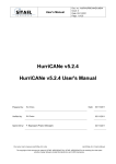
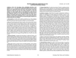
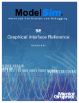
Figure 1 shows the Quartus II/Cadence design flow.
Figure 1. Altera Design Flow with Cadence NC Simulators
Altera IP
Design Entry
Testbench
Functional Simulation
Functional
Models
Synthesis
Place-and-Route
Verilog Output
File (.vo) or VHDL
Output File (.vho)
Standard Delay
Format Output
File (.sdo)
Gate-Level Simulation
2
Gate-Level
Models
Altera Corporation
AN 197: Using Cadence Native Compiler Tools in a Quartus II Design Flow
Functional/Behavioral HDL Simulation
Functional/behavioral HDL simulation verifies the functionality of your
design. After you verify your design, you synthesize it. When you
perform a functional simulation with Cadence NC simulators, you use
your design files (Verilog HDL or VHDL) and the models provided with
the Quartus II software. These Quartus II models are required if your
design uses library of parameterized modules (LPM) functions or Alteraspecific megafucntions. Refer to “Functional/ Behavioral Simulation” on
page 5 for detailed information on how to perform this simulation.
Gate-Level Timing Simulation
After performing place-and-route in the Quartus II software, the software
generates a Verilog Output File (.vo) or VHDL Output File (.vho) and a
Standard Delay Format (SDF) Output File (.sdo) for gate-level timing
simulation. The netlist files map your design to architecture-specific
primitives. The SDF File contains the delay information of each
architecture primitive and routing element specific to your design.
Together, these files provide an accurate simulation of your design with
the selected Altera FPGA architecture. Refer to “Gate-Level Timing
Simulation” on page 21 for detailed information on how to perform this
simulation.
Execution Modes
You can use either the command-line mode or graphical user interface
(GUI) mode to simulate your design with NC simulators. To simulate in
command-line mode, use the files shown in Table 2.
You can launch the NC GUI in UNIX or PC environments by running
nclaunch at a command prompt.
1
Altera Corporation
This application note describes how to perform simulation using
both the command-line and GUI.
3
AN 197: Using Cadence Native Compiler Tools in a Quartus II Design Flow
Table 2. Command-Line Programs
Program
ncvlog or
ncvhdl
Function
NC-Verilog (ncvlog) compiles your Verilog HDL code into a Verilog
Syntax Tree (.vst) file. ncvlog also performs syntax and static
semantics checks.
NC-VHDL (ncvhdl) compiles your VHDL code into a VHDL Syntax
Tree (.ast) file. ncvhdl also performs syntax and static semantics
checks.
ncelab
NC-Elab (ncelab) elaborates the design. ncelab constructs the
design hierarchy and establishs signal connectivity. This program
also generates a Signature File (.sig) and a Simulation SnapShot
File (.sss).
ncsim
NC-Sim (ncsim) performs mixed-language simulation. This program
is the simulation kernel that performs event scheduling and executes
the simulation code.
Quartus II/NC Simulation Flow Overview
The basic Quartus II/Cadence NC simulation flow is described below.
Detailed instructions are given in “Functional/ Behavioral Simulation” on
page 5 and “Gate-Level Timing Simulation” on page 21.
4
1.
Set up your working environment (UNIX only)—For UNIX
workstations, you must set several environment variables to
establish an environment that facilitates entering and processing
designs.
2.
Create user libraries—Create a file that maps logical library names to
their physical locations. These library mappings include your
working directory and any design-specific libraries, e.g., for Altera
LPM functions or megafunctions.
3.
Compile source code and testbenches—You compile your design files
from the command-line using ncvlog (Verilog HDL files) or ncvhdl
(VHDL files) or by using the GUI. During compilation, the NC
software performs syntax and static semantic checks. If no errors are
found, compilation produces an internal representation for each
HDL design unit in the source files. By default, these intermediate
objects are stored in a single, packed library database file in your
working directory.
Altera Corporation
AN 197: Using Cadence Native Compiler Tools in a Quartus II Design Flow
Functional/
Behavioral
Simulation
4.
Elaborate your design—Before you can simulate your model, the
design hierarchy must be defined in a process called elaboration. Use
ncelab in command-line mode or choose Elaborator (Tools menu) in
GUI mode to elaborate the design.
5.
Add signals to your waveform—Before simulating, specify which
signals to view in your waveform using a simulation history
manager (SHM) database.
6.
Simulate your design—You invoke the simulator using the ncsim
program (command-line mode) or by clicking the Play button (GUI
mode).
The following sections provide detailed instructions for performing
functional simulation using the Quartus II software and Cadence NC
tools.
Set Up Your Environment
This section describes how to set up your working environment for the
Quartus II/NC-Verilog or NC-VHDL software interface.
1
1.
(For UNIX workstations only) The information presented here
assumes that you are using the C shell and that your Quartus II
system directory is /usr/quartus. If not, you must use the
appropriate syntax and procedures to set environment variables
for your shell.
(For UNIX workstations only) Add the following environment
variables to your .cshrc file:
setenv QUARTUS_ROOTDIR /usr/quartus
setenv CDS_INST_DIR <NC installation directory>
2.
Add the $CDS_INST_DIR/tools/bin directories to the PATH
environment variable in your .cshrc file. Make sure these paths are
placed before the Cadence hierarchy path.
3.
Add /usr/dt/lib and /usr/ucb/lib to the LD_LIBRARY_PATH
environment variable in your .cshrc file.
4.
Source your .cshrc file by typing source .cshrc r at the
command prompt.
Figure 2 shows an example setting these environment variables.
Altera Corporation
5
AN 197: Using Cadence Native Compiler Tools in a Quartus II Design Flow
Figure 2. Setting Environment Variables
setenv
setenv
setenv
setenv
QUARTUS_ROOTDIR /usr/quartus
CDS_INST_DIR <NC installation directory>
PATH ${PATH}:<NC installation directory>/tools.sun4v/bin:/
LD_LIBRARY_PATH /usr/ucb/lib:/usr/lib:/usr/dt/lib:/usr/bin/X11:<NC installation
directory>/tools.sun4v/lib:$LD_LIBRARY_PATH
setenv QUARTUS_INIT_PATH <NC installation directory>/tools.sun4v/bin
Create Libraries
Before simulating with NC simulators, you must set up libraries using a
file named cds.lib. The cds.lib file is an ASCII text file that maps logical
library names—e.g., your working directory or the location of resource
libraries such as models for LPM functions—to their physical directory
paths. When you launch an NC tool, the tool reads cds.lib to determine
which libraries are accessible and where they are located. NC tools
include a default cds.lib file, which you can modify for your project
settings.
You can use more than one cds.lib file. For example, you can have a
project-wide cds.lib file that contains library settings specific to a project
(e.g., technology or cell libraries) and a user cds.lib file. The following
sections describe how to create/edit a cds.lib file, including:
■
■
Basic Library Setup
LPM Function & Altera Megafunction Libraries
Basic Library Setup
You can create cds.lib with any text editor. The following examples show
how you use the DEFINE statement to bind a library name to its physical
location. The logical and physical names can be the same or you can select
different names. The DEFINE statement usage is:
DEFINE <library name> <physical directory path>
For example, a simple cds.lib for Verilog HDL contains the lines:
DEFINE lib_std /usr1/libs/std_lib
DEFINE worklib ../worklib
Using Multiple cds.lib Files
Use the INCLUDE or SOFTINCLUDE statements to reference another cds.lib
file within a cds.lib file. The syntax is:
6
Altera Corporation
AN 197: Using Cadence Native Compiler Tools in a Quartus II Design Flow
INCLUDE <path to another cds.lib>
or
SOFTINCLUDE <path to another cds.lib>
1
For the Windows operating system, enclose the path to an
included cds.lib file in quotation marks if there are spaces in any
directory names.
For VHDL or mixed-language simulation, you must use an INCLUDE or
SOFTINCLUDE statement in the cds.lib file to include your default cds.lib
in addition to the DEFINE statements. The syntax is:
INCLUDE <path to NC installation>/tools/inca/files/cds.lib
or
INCLUDE $CDS_INST_DIR/tools/inca/files/cds.lib
The default cds.lib file, provided with NC tools, contains a SOFTINCLUDE
statement to include another cds.lib files such as cdsvhdl.lib and
cdsvlog.lib. These files contain library definitions for IEEE libraries,
Synopsys libraries, etc.
Create cds.lib: Command-Line Mode
To edit cds.lib from the command line, perform the following steps:
1.
Create a directory for the work library and any other libraries you
need using the command:
mkdir <physical directory> r
For example:
mkdir worklib r
2.
Using a text editor, create a cds.lib file and add the following line to
it:
DEFINE <library name> <physical directory path>
For example:
DEFINE worklib ./worklib
Altera Corporation
7
AN 197: Using Cadence Native Compiler Tools in a Quartus II Design Flow
Create cds.lib: GUI Mode
To create cds.lib using the GUI, perform the following steps:
1.
Run nclaunch from the command line to launch the GUI.
2.
Choose Set Design Directory (File menu).
3.
Click Create cds.lib File.
4.
Click New under Work Library.
5.
Enter your new work library name, e.g., worklib.
6.
Click OK. The new library is displayed under Work Library.
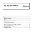
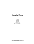
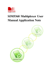
Figure 3 shows an example using the directory name worklib.
Figure 3. Creating a Work Directory in GUI Mode
7.
Click OK.
1
8.
8
You can edit cds.lib by right-clicking the cds.lib filename in
the right pane and choosing Edit from the pop-up menu.
To specify a directory as your working directory, perform the
following steps:
a.
In the right pane of the GUI, right-click the directory name.
b.
Choose Set as Work Library from the pop-up menu. See
Figure 4.
Altera Corporation
AN 197: Using Cadence Native Compiler Tools in a Quartus II Design Flow
Figure 4. Setting Your Current Working Library
After you make this setting, the current working library is
indicated with a helmet icon beside the name, as shown in
Figure 5.
Altera Corporation
9
AN 197: Using Cadence Native Compiler Tools in a Quartus II Design Flow
Figure 5. Current Working Library
LPM Function & Altera Megafunction Libraries
Altera provides behavioral descriptions for LPM functions and Alteraspecific megafunctions. You can implement the megafunctions in a design
using the Quartus II MegaWizard Plug-In Manager or by instantiating
them directly from your design file. LPM functions are named
lpm_<function>. Similarly, Altera-specific megafunctions are named
alt<function>. If your design uses LPM functions or Altera-specific
megafunctions you must set up resource libraries so that you can simulate
your design in NC tools.
1
Many LPM functions and Altera megafunctions use memory
files. You need to convert the memory files for use with NC tools
before simulating.
Altera provides megafunction behavioral descriptions in the files shown
in Table 3. These library files are located in the <Quartus II installation
directory>/eda/sim_lib directory.
10
Altera Corporation
AN 197: Using Cadence Native Compiler Tools in a Quartus II Design Flow
Table 3. Megafunction Behavioral Description Files
Megafunction
Verilog HDL
VHDL
LPM
220model.v
220model.vhd (1)
220pack.vhd (1)
220model_87.vhd (2)
220pack_87.vhd (2)
Altera-Specific
altera_mf.v
altera_mf.vhd (1)
altera_components.vhd (1)
altera_mf_87.vhd (2)
altera_components_87.vhd (2)
Notes:
(1)
(2)
f
Use this model for VHDL 93.
Use this model for VHDL 87.
For more information on LPM functions and Altera-specific
megafunctions, refer to Quartus II Help.
To set up a library for LPM functions, create a new directory and add the
following line to your cds.lib file:
DEFINE lpm <path>/<directory name>
To set up a library for Altera-specific megafunctions, add the following
line to your cds.lib file:
DEFINE altera_mf <path>/<directory name>
Many Altera functional models (220model.v and altera_mf.v) use a
memory file, which is a Hexadecimal (Intel-Format) File (.hex) or a
Memory Initialization File (.mif). However, NC tools cannot read a HEX
or MIF. Perform the following steps to convert these files into a format the
tools can read.
1.
Convert your HEX or MIF into a RAM Initialization File (.rif) by
performing the following steps in the Quartus II software:
1
Altera Corporation
You can also use the hex2rif.exe and mif2rif.exe programs,
located in the <Quartus II installation directory>/bin
directory, to convert the files at the command line. Use the ? flag to view their usage.
a.
Open the HEX or MIF.
b.
Choose Export (File menu).
11
AN 197: Using Cadence Native Compiler Tools in a Quartus II Design Flow
2.
c.
If necessary, in the Export dialog box, select a target directory in
the Save in list.
d.
Select a file to overwrite in the Files list or type the file name in
the File name box.
e.
If necessary, in the Save as type list, select RAM Initialization
File (.rif).
f.
Click Export.
Using a text editor, modify the lpm_file parameter in the
megafunction’s wizard-generated file to point to the RIF.
Alternatively, you can rerun the wizard and point to the RIF as the
memory initialization file.
Compile Source Code & Testbenches
When using NC simulators, you compile files with ncvlog (for
Verilog HDL files or ncvhdl (for VHDL files). Both ncvlog and ncvhdl
perform syntax checks and static semantic checks. If no errors are found,
compilation produces an internal representation for each HDL design unit
in the source files. By default, these intermediate objects are stored in a
single, packed, library database file in your working library directory.
Compilation: Command-Line Mode
To compile from the command line, use one of the following commands.
1
You must specify a work directory before compiling.
Verilog HDL:
ncvlog <options> -work <library name> <design files> r
VHDL:
ncvhdl <options> -work <library name> <design file> r
If your design uses LPM or Altera megafunctions, you also need to
compile the Altera-provided functional models. The following code
shows examples of each.
12
Altera Corporation
AN 197: Using Cadence Native Compiler Tools in a Quartus II Design Flow
Verilog HDL:
ncvlog –WORK lpm 220model.v r
ncvlog –WORK altera_mf altera_mf.v r
1
If your design also uses a memory initialization file, compile the
nopli.v file, which is located in the <Quartus II installation
directory>/eda/sim_lib directory, before you compile your
model. For example:
ncvlog –work lpm nopli.v 220model.v r
ncvlog –work altera_mf nopli.v altera_mf.v r
Alternatively, use the NO_PLI command during compilation:
ncvlog –DEFINE “NO_PLI=1” –work lpm 220model.v r
ncvlog –DEFINE “NO_PLI=1” –work altera_mf
altera_mf.v r
VHDL:
ncvhdl
ncvhdl
ncvhdl
ncvhdl
–V93
–V93
–V93
–V93
–WORK
–WORK
–WORK
–WORK
lpm 220pack.vhd r
lpm 220model.vhd r
altera_mf altera_mf.vhd r
altera_mf altera_mf_components.vhd r
Compilation: GUI Mode
To compile using the GUI, perform the following steps.
Altera Corporation
1.
Right-click a library filename in the NCLaunch window.
2.
Choose NCVlog (Verilog HDL) or NCVhdl (VHDL). The Compile
Verilog and Compile VHDL dialog boxes open. See Figure 6.
Alternatively, you can choose NCVlog or NCVhdl from the Tools
menu.
13
AN 197: Using Cadence Native Compiler Tools in a Quartus II Design Flow
Figure 6. Compiling Verilog HDL & VHDL Files
3.
Click OK in the Compile Verilog or Compile VHDL dialog box to
begin compilation. The dialog box closes and returns you to
NCLaunch.
1
The command-line equivalent argument displays at the
bottom of the NCLaunch window.
Elaborate Your Design
Before you can simulate your model, you must define the design
hierarchy in a process called elaboration. With NC simulators, you use the
language-independent ncelab program to elaborate your design. The
ncelab program constructs a design hierarchy based on the design’s
instantiation and configuration information, establishes signal
connectivity, and computes initial values for all objects in the design. The
elaborated design hierarchy is stored in a simulation snapshot, which is
the representation of your design that the simulator uses to run the
simulation. The snapshot is stored in the library database file along with
the other intermediate objects generated by the compiler and elaborator.
14
Altera Corporation
AN 197: Using Cadence Native Compiler Tools in a Quartus II Design Flow
1
If you are running the NC-Verilog simulator using the singlestep invocation method (ncverilog), and want to compile your
source files and elaborate the design with one command, use the
+elaborate option to stop the simulator after elaboration. For
example: ncverilog +elaborate test.v r .
Elaboration: Command-Line Mode
To elaborate your Verilog HDL or VHDL design from the command line,
use the following command:
ncelab <options> <library>.Cell:<view> r
For example:
ncelab worklib.lpm_ram_dp_test:entity r
You can set your simulation timescale using the –TIMESCALE <arguments>
option. You do not need to specify the timescale if your top-level file
already has a TIMESCALE directive. For example:
ncelab –TIMESCALE 1ps/1ps worklib.lpm_ram_dp_test:entity r
1
f
For more information on the ncls program, refer to the Cadence
NC-Verilog Simulator Help or Cadence NC-VHDL Simulator Help.
1
Altera Corporation
To view the elements in your library and which views are
available, use the ncls program. For example the command
ncls –library worklib r displays all of the cells and their
views in your current worklib directory.
If you are running the NC-Verilog simulator using multistep
invocation, run ncelab with command-line options as shown
above. You can specify the arguments in any order, but
parameters to options must immediately follow the options they
modify.
15
AN 197: Using Cadence Native Compiler Tools in a Quartus II Design Flow
Elaboration: GUI Mode
To compile using the GUI, perform the following steps.
1.
Expand your current working library in the right pane.
2.
Select and open the entity/module name you want to elaborate.
3.
Right-click the view you want to display.
4.
Choose NCElab. The Elaborate dialog box opens. Alternatively, you
can choose Elaborator from the Tools menu.
5.
Set the simulation timescale using the command –TIMESCALE
<arguments> under Other Options. See Figure 7.
Figure 7. Elaborating the Design
6.
16
Click OK in the Elaborate dialog box to begin elaboration. The
dialog box closes and returns you to NCLaunch.
Altera Corporation
AN 197: Using Cadence Native Compiler Tools in a Quartus II Design Flow
Add Signals to View
You use a simulation history manager (SHM) database, which is a
Cadence proprietary waveform database to store the selected signals you
want to view. Before you can specify which signals to view, you must
create this database by adding commands to your code. Additionally, you
may want to create a Value Change Dump File (.vcd) to store the
simulation history.
f
For more information on using a .vcd, refer to the NC-Sim user manual.
Adding Signals: Command-Line Mode
To create a SHM database you specify the system tasks described in
Table 4 in your Verilog HDL code.
1
For VHDL, you can use the Tcl command interface or C function
calls to add signals to a database. Refer to Cadence
documentation for details.
Table 4. SHM Database System Tasks
System Task
Description
$shm_open(“<filename>.shm”); Open database. You can provide a filename; if you do not specify one, the
default is waves.shm. You must create a database before you can open
it; if one does not exist, the tools create it for you.
$shm_probe(“[A|S|C]”);
Probe signals. You can specify the signals to probe; if you do not specify
signals, the default is all ports in the current scope.
A probes all nodes in the current scope.
S probes all nodes below the current scope.
C probes all nodes below the current scope and in libraries.
$shm_save;
Save the database.
$shm_close;
Close the database.
Figure 8 shows a simple example.
Figure 8. Example SHM Verilog HDL Code
initial
begin
$shm_open (“waves.shm”);
$shm_probe (“AS”);
end
Altera Corporation
17
AN 197: Using Cadence Native Compiler Tools in a Quartus II Design Flow
f
For more information on these system tasks, refer to the NC-Sim user
manual.
Adding Signals: GUI Mode
To add signals in GUI mode, perform the following steps.
1.
Load the design.
a.
Click the + icon next to the Snapshots directory to expand it.
b.
Right-click the lib.cell:view you want to simulate.
c.
Choose NC-Sim from the pop-up menu.
d.
Click OK in the Simulate dialog box.
After you load the design, the SimControl window appears as
shown in Figure 9.
Figure 9. SimControl Window
18
Altera Corporation
AN 197: Using Cadence Native Compiler Tools in a Quartus II Design Flow
2.
Open the Navigator window by clicking the Navigator icon in the
SimControl window toolbar as shown in Figure 10.
Figure 10. Navigator Icon in the Toolbar
3.
Select the signals you want to view by clicking the signal names.
4.
Click the Waveform View icon. See Figure 11.
Figure 11. Selecting Signals in the Navigator Window
A waveform viewer appears with all of your signals. You can traverse
through the hierarchy by double-clicking the instance name in the left
pane.
You are now ready to simulate your testbench/design.
Simulate Your Design
After you have compiled and elaborated your design, you simulate using
ncsim. The ncsim program loads the ncelab-generated snapshot as its
primary input. It then loads other intermediate objects referenced by the
snapshot. If you enable interactive debugging, it may also load HDL
source files and script files. The simulation output is controlled by the
model or debugger. The output can include result files generated by the
model, SHM database, or VCD.
Altera Corporation
19
AN 197: Using Cadence Native Compiler Tools in a Quartus II Design Flow
Functional Simulation: Command-Line Mode
To perform functional simulation of your Verilog HDL or VHDL design
from the command line, use the following command:
ncsim <options> <library>.Cell:<view> r
For example:
ncsim worklib.lpm_ram_dp:syn r
Table 5 shows some of the options you can use with ncsim.
Table 5. ncsim options
Options
Description
-gui
Launch GUI mode.
-batch
Used for non-interactive mode.
-tcl
Used for interactive mode (not required when –gui is used).
Functional Simulation: GUI Mode
You can run and step through simulation of your Verilog HDL or VHDL
design in the GUI. Click the Play button shown in Figure 12 to begin
simulation. Figure 12 also describes other useful simulation buttons.
1
If you skipped “Add Signals to View” on page 17, you must load
the design before simulating. Refer to “step 1. Load the design.”
on page 18 for instructions.
Figure 12. Simulation Toolbar Buttons
Run the simulation
until it finishes or
until the next
breakpoint.
20
Advance the simulation to the next executable line in
any scope, stepping into subprogram calls.
Advance the simulation to the next executable line
in any scope, stepping over subprogram calls.
Altera Corporation
AN 197: Using Cadence Native Compiler Tools in a Quartus II Design Flow
Gate-Level
Timing
Simulation
The following sections provide detailed instructions for performing
timing simulation using Quartus II output files and simulation libraries
and Cadence NC tools.
Quartus II Simulation Output Files
When you compile your Quartus II design, the software generates
Verilog HDL netlist file (.vo) or VHDL netlist file (.vho) and a Standard
Delay Format (SDF) Output File (.sdo) that are compatible with Cadence
NC simulators. To generate these files, perform the following steps in the
Quartus II software.
1.
Choose EDA Tool Settings (Assignment menu).
2.
Choose Simulation under Tool type.
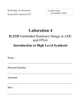
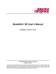
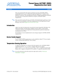
3.
Choose NcSim (Verilog HDL output from Quartus II) or NcSim
(VHDL output from Quartus II). See Figure 13.
4.
Click OK.
5.
Choose Start Compilation (Processing menu).
During compilation, the Quartus II software automatically creates the
directory simulation/ncsim, which contains the Verilog Output File,
VHDL Output File, and SDF Output File for timing simulation.
Altera Corporation
21
AN 197: Using Cadence Native Compiler Tools in a Quartus II Design Flow
Figure 13. Quartus II EDA Tool Settings
Quartus II Timing Simulation Libraries
Altera device simulation library files are provided in the <Quartus II
installation directory>/eda/sim_lib directory. The Verilog Output File or
VHDL Output File requires the library for the device your design targets.
For example, the Stratix family has the following libraries:
■
■
■
stratix_atoms.v
stratix_atoms.vhd
stratix_components.vhd
Therefore, if your design targets a Stratix device, you need to set up the
appropriate mappings in your cds.lib. Refer to “Create Libraries” on
page 23 for more information.
Set Up Your Environment
Set up your working environment for the Quartus II/NC-Verilog or
NC-VHDL software interface. Refer to the instructions in “Set Up Your
Environment” on page 5 for details.
22
Altera Corporation
AN 197: Using Cadence Native Compiler Tools in a Quartus II Design Flow
Create Libraries
Create libraries for your simulation, including:
f
■
A working library
■
The library for the device family your design targets using the file
<path>/eda/sim_lib/<device family>_atoms.<v|vhd>
■
If your design contains the altgxb megafunction, map to the
precompiled Stratix GX timing simulation model libraries using the
mapping <path>/eda/sim_lib/ncsim/<verilog|vhdl>/stratixgx_gxb.
Refer to “Basic Library Setup” on page 6 and “LPM Function & Altera
Megafunction Libraries” on page 10 for step-by-step instructions on
creating libraries.
Compile the Project Files & Libraries
Compile the project files and libraries into your work directory using the
ncvlog or ncvhdl programs or the GUI. You should compile the following
items:
■
■
■
■
f
Testbench file
Your Quartus II output netlist file (.vo or .vho)
Atom netlist file for the device family <device family>_atoms.<v|vhd>
For VHDL, <device family>_components.vhd
Refer to “Compile Source Code & Testbenches” on page 12 for step-bystep instructions on compiling.
Elaborate the Design
When you elaborate your design, you must include the SDF Output File
(.sdo). For Verilog HDL, this process happens automatically. The
Quartus II-generated Verilog HDL netlist file calls the SDF file using the
system task call $sdf_annotate. When NC-Verilog elaborates the netlist,
ncelab recognizes the system task and automatically calls nsdfc. However
the $sdf_annotate system task call does not specify the path. Therefore,
you must copy the .sdo from the Quartus II-created simulation directory
to the NC working directory in which you run the ncelab program. After
you update the path, you can elaborate the design. Refer to “Elaborate
Your Design” on page 14 for step-by-step instructions on elaboration.
Altera Corporation
23
AN 197: Using Cadence Native Compiler Tools in a Quartus II Design Flow
For VHDL, the Quartus II-generated VHDL netlist file has no system task
calls to locate your SDF file. Therefore, you must compile the .sdo
manually. Refer to “Compiling the Standard Delay Output File (VHDL
Only): Command Line” and “Compiling the Standard Delay Output File
(VHDL Only): GUI” on page 25 for information on compiling the .sdo.
Compiling the Standard Delay Output File (VHDL Only): Command Line
To annotate the .sdo timing data from the command line, perform the
following steps:
1.
Compile the .sdo using the ncsdfc program by typing the following
command at the command prompt:
ncsdfc <project name>_vhd.sdo –output <output name> r
The ncsdfc program generates a <output name>.sdf.X compiled SDF
Output File.
1
2.
If you do not specify an output name ncsdfc uses <project
name>.sdo.X.
Specify the compiled .sdo for the project by adding the following
lines to an ASCII SDF command file for the project:
COMPILED_SDF_FILE = "<project name>.sdf.X"
SCOPE = <instance path>
Figure 14 shows an example SDF command file.
Figure 14. Example SDF Command File
// SDF command file sdf_file
COMPILED_SDF_FILE = "lpm_ram_dp_test_vhd.sdo.X",
SCOPE = :tb,
MTM_CONTROL = "TYPICAL",
SCALE_FACTORS = "1.0:1.0:1.0",
SCALE_TYPE = "FROM_MTM";
After you compile the .sdo, execute the following command to elaborate
the design:
ncelab worklib.<project name>:entity –SDF_CMD_FILE <compiled
SDF> r
24
Altera Corporation
AN 197: Using Cadence Native Compiler Tools in a Quartus II Design Flow
Compiling the Standard Delay Output File (VHDL Only): GUI
To annotate the .sdo timing data in the GUI, perform the following steps:
1.
Choose SDF Compiler (Tools menu).
2.
In the SDF File box, specify the name of the SDF Output File for the
project.
3.
Make sure <project name>.sdf.X appears in the Output file name
box.
4.
Click OK.
When you are finished compiling the .sdo, you can elaborate the design.
Refer to “Elaboration: GUI Mode” on page 16 for step-by-step
instructions, however, before clicking OK to begin elaboration, perform
the following additional steps:
1.
Click Advanced Options.
2.
Click Annotation in the left pane.
3.
Turn on the Use SDF File option in the right pane.
4.
Click Edit.
5.
Browse to the location of the .sdo and click OK.
6.
Click OK.
Add Signals to View
If you want to add signals to view, refer to the steps in “Add Signals to
View” on page 17.
Simulate Your Design
Simulate your design using the ncsim program as described in “Simulate
Your Design” on page 19.
Altera Corporation
25
AN 197: Using Cadence Native Compiler Tools in a Quartus II Design Flow
Incorporating
PLI Routines as
Dynamic
Libraries
Designers frequently use programming language interface (PLI) routines
in Verilog HDL testbenches, to perform user- or design-specific functions
that are beyond the scope of the Verilog HDL language. Cadence NC
simulators include the PLI wizard, which helps you incorporate your PLI
routines.
For example, if you are using a HEX File for memory, you can convert it
for use with NC tools using the Altera-provided convert_hex2ver
program. However, before you can use this program, you must build it
and place it in your project directory using the PLI wizard.
This section describes how to create dynamic PLI libraries using the
convert_hex2ver program as an example. The convert_hex2ver source
files are located in the <installation path>/eda/cadence/verilog-xl
directory:
■
■
■
convert_hex2ver.c
veriuser.c
convert_hex2ver.obj
To create a PLI dynamic library (.so) from these files, perform the
following steps:
26
1.
Start the PLI wizard by executing pliwiz r at the command prompt.
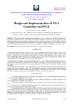
2.
In the Config Session Name and Directory page, type the name of
the session in the Config Session Name box and type the directory
in which the file should be built in the Config Session Directory
box. Click Next. See Figure 15.
Altera Corporation
AN 197: Using Cadence Native Compiler Tools in a Quartus II Design Flow
Figure 15. Specify the Session Name
3.
In the Select Simulator/Dynamic Libraries page, select the
Dynamic Libraries Only option, as shown in Figure 16.
Figure 16. Dynamic Libraries Option
Altera Corporation
4.
Click Next.
5.
In the Select Components page, turn on the PLI 1.0 Applications
option.
27
AN 197: Using Cadence Native Compiler Tools in a Quartus II Design Flow
6.
Select libpli. See Figure 17.
Figure 17. Select PLI Components
7.
Click Next.
8.
In the Select PLI 1.0 Application Input page, select Existing
VERIUSER (source/object file).
9.
Select Source File.
10. Click the browse button to locate the veriuser.c file that is provided
with the Quartus II software. See Figure 18.
28
Altera Corporation
AN 197: Using Cadence Native Compiler Tools in a Quartus II Design Flow
Figure 18. Specify PLI Application Input
11. Click Next.
12. In the PLI 1.0 Application page, click browse under PLI Source Files
to locate the convert_hex2ver.c file. See Figure 19.
Figure 19. PLI Application Files
Altera Corporation
29
AN 197: Using Cadence Native Compiler Tools in a Quartus II Design Flow
13. Click Next.
14. In the Select Compiler page, choose your C compiler from the Select
Compiler list box. See Figure 20.
Figure 20. Select Compiler
15. Click Next.
16. Click Finish.
17. When you are asked if you want to build your targets now, click Yes.
The software calls your C compiler to compile the files. Figure 21
shows an example output.
30
Altera Corporation
AN 197: Using Cadence Native Compiler Tools in a Quartus II Design Flow
Figure 21. Example PLI Compilation Output
18. Compilation creates the file libpli.so (libpli.dll for PCs), which is
your PLI dynamic library, in your session directory. When you
elaborate your design, the elaborator looks through the path
specified in the LD_LIBRARY_PATH (UNIX) or PATH (PCs)
environment variable, searches for the .so/.dll file, and loads them
when needed.
1
You must modify LD_LIBRARY_PATH or PATH to include
the directory location of your .so/.dll file.
Conclusion
The Cadence NC family of simulators work within an Altera FPGA design
flow to perform functional and timing simulation easily and accurately.
Altera provides functional models of LPM and Altera-specific
megafunctions that you can compile with your testbench or design. For
timing simulation, you use the atom netlist file generated by Quartus II
compilation. The seamless integration of the Quartus II software and
Cadence NC tools make this simulation flow an ideal method for fully
verifying an FPGA design.
References
■
■
■
Altera Corporation
Cadence NC-Verilog Simulator Help
Cadence NC VHDL Simulator Help
Cadence NC Launch User Guide
31
AN 197: Using Cadence Native Compiler Tools in a Quartus II Design Flow
101 Innovation Drive
San Jose, CA 95134
(408) 544-7000
www.altera.com
Applications Hotline:
(800) 800-EPLD
Literature Services:
[email protected]
32
Copyright 2003 Altera Corporation. Altera, The Programmable Solutions Company, the stylized Altera logo,
specific device designations, and all other words and logos that are identified as trademarks and/or service
marks are, unless noted otherwise, the trademarks and service marks of Altera Corporation in the U.S. and
other countries. All other product or service names are the property of their respective holders. Altera products
are protected under numerous U.S. and foreign patents and pending applications, maskwork rights, and
copyrights. Altera warrants performance of its semiconductor products to current
specifications in accordance with Altera’s standard warranty, but reserves the right to
make changes to any products and services at any time without notice. Altera assumes no
responsibility or liability arising out of the application or use of any information, product,
or service described herein except as expressly agreed to in writing by Altera Corporation.
Altera customers are advised to obtain the latest version of device specifications before
relying on any published information and before placing orders for products or services.
All rights reserved.
Altera Corporation