1
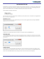
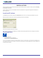
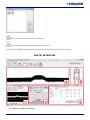
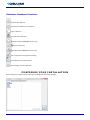
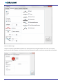
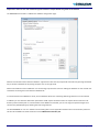
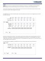
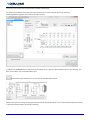
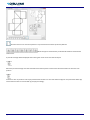
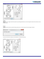
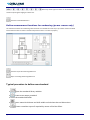
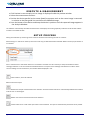
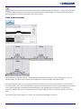
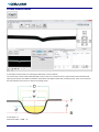
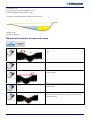
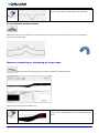
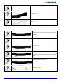
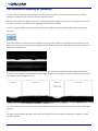
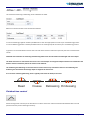
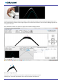
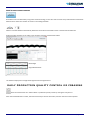
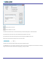
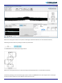
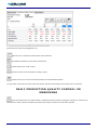
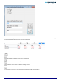
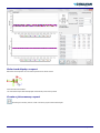
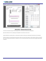
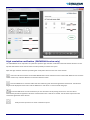
OCT 100 User Manual Cerulean Rockingham Drive, Linford Wood East, Milton Keynes MK14 6LY, England Telephone +44 (0) 1908 233833 Fax: +44 (0) 1918 235333 Introduction ......................................................................................................................................................................................................... 3 PREMIUM version................................................................................................................................................................... 3 CREASING RULE ...................................................................................................................................................................... 3 POWER CREASE ...................................................................................................................................................................... 3 Safety Instructions ............................................................................................................................................................................................... 5 Warning ........................................................................................................................................................................................................... 5 General safety rules ......................................................................................................................................................................................... 5 Installation ........................................................................................................................................................................................................... 6 Install the OCT software .................................................................................................................................................................................. 6 Run the application .......................................................................................................................................................................................... 6 Main Window ...................................................................................................................................................................................................... 7 Main Window Icons ............................................................................................................................................................................................. 9 Main Menu Functions ...................................................................................................................................................................................... 9 Camera Functions ............................................................................................................................................................................................ 9 Setup Statistics and Job Statistics Functions .................................................................................................................................................... 9 Reference Database Functions ...................................................................................................................................................................... 10 Configure your installation ................................................................................................................................................................................ 10 Standards Database ........................................................................................................................................................................................... 14 The Box Layout Editor (PREMIUM Version only) ............................................................................................................................................... 17 Define measurement locations for embossing (power crease only) ............................................................................................................. 20 Typical procedure to define new standard .................................................................................................................................................. 20 Initialize the camera .......................................................................................................................................................................................... 21 Measurement functions: ................................................................................................................................................................................... 21 Execute a measurement .................................................................................................................................................................................... 22 Setup Process .................................................................................................................................................................................................... 22 Bead measurements ...................................................................................................................................................................................... 23 Crease measurement ..................................................................................................................................................................................... 24 Manual measurement of bead and crease .................................................................................................................................................... 25 Cross Section measurement .......................................................................................................................................................................... 26 Measure embossing or debossing on large areas .......................................................................................................................................... 26 Fine structured Embossing or Debossing ....................................................................................................................................................... 28 Finished box control ...................................................................................................................................................................................... 29 Multi Crease measurements ................................................................................................................................................ 31 Daily production quality control or creasing...................................................................................................................................................... 31 Daily production quality control or embossing .................................................................................................................................................. 34 Statistics............................................................................................................................................................................................................. 36 Select and display a report ............................................................................................................................................................................ 37 Create a job summary report......................................................................................................................................................................... 37 Device verification ............................................................................................................................................................................................. 38 High resolution verification (PREMIUM Version only) ................................................................................................................................... 39 page 2 of 40 Cerulean OCT 100 Manual Stock Code: 90151 Nov. 2014 I N T R OD U C T I O N Congratulations! You have just acquired the portable creasing and folding analyzer (OCT). This device is the optimum tool to control the converting process of creasing. It measures the characteristics of the bead, the spine, the folding symmetry and angle in a fast and intuitive manner. The software automatically creates quality control reports. The OCT software is available in two versions: Basic Version PREMIUM Version This manual will always outline functions that are available only in the premium version. The software can be upgraded from Basic to Premium by an upgrade code. PREMIUM version Contact your dealer to get the proper upgrade code for your device. Insert the upgrade codes by selecting the PREMIUM upgrade function from the Help menu. In addition there are offered optional function modules. These modules require the PREMIUM license. CREASING RULE The Creasing Rule function enables you to measure the characteristics of your creasing rules. The function can be accessed only if the CREASING RULE Code is inserted. Insert the CREASING RULE code by selecting the Creasing Rule License Item from the Help menu. POWER CREASE The Power Crease function offers additional job statistics for crease and embossing measurements. Also additional crease profile calculations are available with this function module. The function can be accessed only if the POWER CREASE Code is inserted. Insert the POWER CREASE code by selecting the Power Crease License Item from the Help Menu. Cerulean OCT 100 Manual Stock Code: 90151 Nov. 2014 page 3 of 40 Important: This manual describes the current version of the OCT hardware and software. Future enhancements or modifications are reserved. page 4 of 40 Cerulean OCT 100 Manual Stock Code: 90151 Nov. 2014 S A F E T Y I N S T R U C T I ON S Warning For safety reasons it is absolutely necessary to read through the user’s guide and all of the instructions it contains. General safety rules If the safety recommendations and instructions in this User Guide are not complied with, measurement errors or data loss or physical injury or property damage may result The OCT is not intrinsically safe. Therefore the device cannot be used in an environment with explosive vapors where there is a risk of spark ignition. The OCT may not be used in an area with strong electromagnetic fields. Use the OCT in ambient temperatures between 10°C (50° F) and 40°C (104°F), and do not expose the OCT to direct sun light. The OCT Sensor should never be opened as there are no user-serviceable parts. Doing so voids the guarantee. Contact your authorized dealer if repairs are necessary. To avoid incorrect handling, the OCT should only be used by trained personnel The OCT should only be used on dry measurement objects. The OCT should be protected against chemicals, corrosive vapors, strong mechanical vibrations and impacts. Use original spare parts and accessories only. Use the original packaging exclusively when transporting. The OCT casing can be cleaned with a dry cloth. Cerulean OCT 100 Manual Stock Code: 90151 Nov. 2014 page 5 of 40 INSTALLATION Start your Computer and wait until all boot processes have terminated and your computer is ready to operate. Do not plug the USB cable in at this time. Plug the USB Memory Stick into a free USB Port and wait until Windows has recognized and registered the USB Stick as a Mass storage Device. Install the OCT software The USB Memory stick contains a setup utility ‘setup OCT.exe’, which can be run to install the OCT Software on your PC. Before termination the video driver installer will automatically be started. Click INSTALL. Wait until the installation of the driver is finished. Now connect the USB cable to a free USB2.0 port. Windows will automatically detect the driver and assign it to the device. Run the application Launch the OCT.exe, Click the OCT Icon on your desktop or, Run the OCT from the Windows Start Menu You can use one Software installation for multiply Hardware. Copy the ‘<serialnumber>_OCT.INI’ file from the USB Stick into the Installation directory of your computer. If more than one of those files is located at program start, than the software will prompt for Device selection: page 6 of 40 Cerulean OCT 100 Manual Stock Code: 90151 Nov. 2014 Select a device from the list and click the preview Icon. Click the Cancel Icon to maintain the most recently used device. You can always change the connected device by selecting the ‘Select Device’ item from the ‘Device’ Menu. M A I N W I N D OW A) Captured image for analysis Cerulean OCT 100 Manual Stock Code: 90151 Nov. 2014 page 7 of 40 B) C) D) E) Box definition window Live Image of camera Analysis types and grafical results Numerical Results and Report preview page 8 of 40 Cerulean OCT 100 Manual Stock Code: 90151 Nov. 2014 M A I N W I N D OW I C O N S Main Menu Functions Measure a new box in production quality control Measure new embossing-debossing job (Power Crease only) Save actual image Load Image Open Standards Database Open Statistics on quality reports Analyze image Camera Functions Preview Capture Setup Statistics and Job Statistics Functions Clear statistics Add most recent measurement and all future measurements to statistics automatically and re-calculate average, maximum and minimum and Standard Deviation. Click this icon again to stop adding measurements to statistics. Remove most recent measurement from Statistics. Save actual statistical data Accept and save data – create PDF report. Cancel box data collection Cerulean OCT 100 Manual Stock Code: 90151 Nov. 2014 page 9 of 40 Reference Database Functions Add new Box reference Remove Box reference from Database Copy a reference Calculate tool dimensions Select Box Layout (PREMIUM Version only) Measure references Open Box Editor (PREMIUM Version only) Get a proposal fort he brightness settings Save Database and close Window Undo changes and close Window C ON F I G U R E Y OU R I N S T A L L A T I ON Select Settings from the file menu. Select your language from the Language page. page 10 of 40 Cerulean OCT 100 Manual Stock Code: 90151 Nov. 2014 You can protect additional settings by password. Check or un-check the Password protection item on the right bottom. Insert the password <creasing> to make your choice permanent. The password protection will disable the modifications of all settings. Only the language can still be selected. Further the modification of references will be disabled by this function. Select the Additional page and change between metric system (mm) and Imperial (inch) system select the number of significant digits for measurement results select the number of beads in case of multi bead measurements. If 1 is selected, then the software will automatically detect the number of beads. select History if the previous measurement should be displayed by a red line or the previous measurement is not displayed at all. Select the mathematical formula for the opening calculation in crease measurement. Narrow opening is an alternative interpretation for the starting and ending of a creasing line cross section on the material surface. Select if a noise filter should be applied to the surface profile curve and how strong this filter should be (values 0 = no filter, 10 = very strong filter). The noise filter will reduce the impact of surface structure like fibers, print or gloss. Please note, that a noise filter always makes the curves smooth and therefore eliminates drawing details. It can appear little differences in measurement values depending on the filter setting. It is recommended to use filter setting 0 if very tiny structures should be measured (like cut score lines) . On rough surfaces, glossy surfaces or printed surfaces the noise filter can help to improve the repeatability of the readings. In case the Power Crease Module is activated there is a separate filter setting for crease measurements. In addition the level for the crease width measurement can be selected. Insert a value followed by % to specify a percentage level. Insert a value without % to specify the level in microns. The level is always calculated starting from the bottom of the crease. Enable and disable measurement functions Cerulean OCT 100 Manual Stock Code: 90151 Nov. 2014 page 11 of 40 Select the Reports page Load your company Logo that will be applied to your quality reports by clicking the File Open Icon. Insert your company details below as they will appear in the header of any report. Specify the output format for tab delimited text format output. page 12 of 40 Cerulean OCT 100 Manual Stock Code: 90151 Nov. 2014 Important: in order to save and re-load setup process data the ‘Output Header’ flag needs to be checked. The PREMIUM version offers in addition the software configuration page. Select the file location of the reference database. Type the file name into the proper field and confirm by pressing the ENTER key or select the database file by clicking the open Icon on the right hand. Select if the database can be modified or not. Use this flag to prevent the user from editing the database in case of multi-user installations accessing the same reference database file. In case the Power Crease Module is active, also the database file for the embossing-debossing references can be selected. In addition you can select the destination path where all PDF reports should be saved. The reports will be saved into subdirectory of the selected path. In case the Power Crease Module is activated, you can save original captured images into a sub directory \SetupRep\Img by selecting the Save Image Selector. The OCT PREMIUM can run on a network communicating with a server application based on two communication protocols: TCP-IP e HOT FOLDER. For details check the manual CREASY Host Interface.pdf. Cerulean OCT 100 Manual Stock Code: 90151 Nov. 2014 page 13 of 40 S T A N D A R D S D A T A BA S E The OCT software offers a database with standards. Click the database icon to open the database interface. OCT You can maintain your own database by adding or removing records from the database. Click the ADD Icon to add a new record. Compile the fields and click OK. Select the record from the list that you would like to remove from the database. Click the delete icon to remove the record from the list. Create a new reference record and copy the data of the selected record into the new record Select the record from the list you would like to modify. Modify the data and click OK. The Bead and Spine dimensions as well as the requirements for the crease channel dimensions differ depending on the direction of the crease and fibers of the material. The standard database offers four different references (A), (B), (C), and (D) . In case of PREMIUM version there can be used up to 7 different references whereby the naming of the references can be selected with the box editor (see below). The crease of type B are assumed to be perpendicular to the crease of type A. The orienation of the package can be defined as A being parallel to fibers or A being orthogonal to fibers. Create a new reference by clicking the Icon. Insert a new name into the Standard field. Select the orientation of the A-crease Based on material thickness, tool width and fiber orientation you can calculate a proposal for the crease channel specifications for A and B by clicking the calculator Icon. If you would like to use other specifications, type the new values into the proper edit fields. Select the camera settings to be used to measure this material: page 14 of 40 Cerulean OCT 100 Manual Stock Code: 90151 Nov. 2014 Position the Device on a typical bead of the target material. Click this icon. The Software will automatically test different settings and select the best setting for the current material. The selection will be confirmed by a beep. There are four sets (A), (B), (C), and (D), of references for each record: one for crease parallel to fibers and one for crease perpendicular to fibers and two diagonoal crease types. The PREMIUM version of the OCT Software offers seven sets of references per box that can be configured by means of the box editor (see below). Specify the noise filter for this reference. The nois filter always removes tiny details of the measured profile such as there might appear small differences in measurement reasults between filter and no filter. It is recommended to use a filter on rough surface, glossy surface or surface with print with it is recommended to use no filter (value = 0) in case sharp corners or very small objects need to be measured. In case the Power Crease Module is activated there can also be inserted references for crease measurement. ´ Cerulean OCT 100 Manual Stock Code: 90151 Nov. 2014 page 15 of 40 In case of crease measurement insert the level of width measurement. The Power Crease Module also supports the use of references for embossing and de bossing. Select the embossing/debossing page to insert references and tolerances. In addition the PREMIUM version implements the possibility to link a specific customized Box Layout to any reference. The Basic version offers only one standard Box Layout. Click the Box Layout selection Icon to open the list of available Box Layouts. Select a Box Layout by clicking into the graphical display of the proper Box Layout. Link the selected Box Layout permanently to the actual selected refence by clicking the OK icon. page 16 of 40 Cerulean OCT 100 Manual Stock Code: 90151 Nov. 2014 In case there has not yet been defined a Box layout, you can open the box editor by clicking the Box editor Icon. Define a Box Layout and link it to the actual reference set as described above. Reference values can also be defined by measuring samples. Click the Measure sample icon of the proper column to start the measurement process. Measure the bead of the samples. Finally click OK to permanently save the new reference values. T H E B OX L A YO U T E D I T O R ( P R E M I U M VE R S I O N O N L Y) Open the Box Layout Editor by selecting the Box Editor from the Tools menu. Open an existing Box Layout or import a Box Layout from any JPG File. The import will automatically resize the Box Layout for the 3 resolutions required by the OCT Software. As an alternative you can retrieve the source image by selecting it in the PDF file, copy it to the Windows clipboard and clicking the past icon of the Box editor. In case the source image does not show high contrast edges, the past can be performed applying a filter. Select the proper area in the source PDF file, copy the image, and click the filtered past Icon. You can also load one of the predefined box layouts from the library by clicking the LIB Icon. Reload previously defined box blank layouts by clicking the box blank Icon. Cerulean OCT 100 Manual Stock Code: 90151 Nov. 2014 page 17 of 40 Click the clear Icon to clear the layout from any measurement locations previously defined. Select the type of measurement you would like to define measurement locations for. A preview rectangle will be displayed when moving the mouse arrow over the box layout Move the preview rectangle over the intended measurement position and click the left mouse button to store the new position Continue to click on positions until all [A] measurement locations are set. Now select the [B] icon and proceed to define [B] measurement locations. Proceed with [C] and [D] accordingly. page 18 of 40 Cerulean OCT 100 Manual Stock Code: 90151 Nov. 2014 Remove a single measurement position by selecting the Remove Icon and clicking with the left mouse button into the proper position. Rename a position by double clicking the proper icon and inserting a new name (singel character) All positions that have already been inserted will be renamed automatically Cerulean OCT 100 Manual Stock Code: 90151 Nov. 2014 page 19 of 40 Below any crease type icon there can be selected the number of creases composing the folging line of the box. Save the actual Box definition Define measurement locations for embossing (power crease only) The reference locations for embossing measurements are inserted the same way as you did for crease and bead measurement locations. Select a box blank layout and insert A..F locations properly. Save the layout as Embossing Reference Open an existing Embossing Reference. Typical procedure to define new standard Open the standards library window Create a new empty standard Insert the standard Identifier Insert material thickness and knife width and calculate the tool dimensions. Create a new Box Layout if required by means of the Box Editor. page 20 of 40 Cerulean OCT 100 Manual Stock Code: 90151 Nov. 2014 Link the new Box Layout to the standard by selecting it from the list. Get a proposal for the brightness settings Measure reference boxes that perform properly on the packaging line for any single crease type. Insert tolerances Save the standard permanently into the database. INITIALIZE THE CAMERA Click Preview to start the Live Image of the camera A flashing left dot shows that the camera is active. A steady right dot shows that the key at the device has been pressed, a new image has been captured, and the software is analyzing the image. Select the brightness type (white, gray, black) of the substrate. Use the scroll bare to fine tune the brightness. White (or light gray) card board can be analyzed with the standard setting shown below. M E A S U R E M E N T F U N C T I ON S Measure bead characteristics Measure crease characteristics Measure subsequently bead and crease characteristics and overlay images to obtain cross section image Measure embossing or de-bossing areas Measure fine structured embossing or de-bossing areas as for example text. Measure the folding characteristics of the finished box. Multi Crease Measurement Cerulean OCT 100 Manual Stock Code: 90151 Nov. 2014 page 21 of 40 E XE C U T E A M E A S U R E M E N T Click Preview in case actually no Live Image is displayed inside the preview window Select the measurement function Position the device parallel to the crease (bead) to measure such as the crease image is centered in relation to the blue guide line overlaid to the PREVIEW image. Press the button of the device and keep the device in position until the captured image appears in the Analysis Window The software automatically calculates the dimensions and displays the results graphically inside the result window and the numbers in the table window S E T U P P R OC E S S Setup your embosser by measuring various locations of beads and collecting the data in a statistic. When testing in a new box or material, there will not be any pre-defined standard available. Make sure the proper selector is un-checked. Once a reference for a card board material or a box blank is available it is still necessary to setup the embosser before starting production. In this case check the Standard selector to compare actual readings with reference numbers. If the current readings are out of tolerance, the numbers will be displayed in red. Clear statistics, start new statistics Measure the first sample Add the first sample measurement to the statistics. All future measurements are automatically added to the statistics until this Icon is clicked again. Delete most recent measurement from the statistics. Click the OK Icon to create a PDF report of the actual statistics. The report is automatically saved and can be printed. page 22 of 40 Cerulean OCT 100 Manual Stock Code: 90151 Nov. 2014 Click the save icon to save all measurement data into a tab delimited text file. Important: in order to re-load the data to continue adding readings it is necessary to have checked the option ‘Output Header’ in the settings window. Reload the data by clicking the ‘Load measurement data’ Item in the File menu. Bead measurements The vertical axis (Y) of graphical display is zoomed by a factor displayed in the left top corner of the graph (Y:X = 3.4 : 1 in above example). This makes it easy to identify minor differences in shape and height of the Bead or Spine. The optimum bead is drawn as a gray background based on the reference values of the active reference. The actual bead curve is displayed in black color. The bead width is displayed on top of the window. The bead height is displayed on top of the curve. Left and right angle are displayed at the left folding point and right folding point respectively. The symmetry is displayed as difference between the perpendicular of the maximum height position to the base line and the centre of the bead. The previous measurement displays as a red line. The average bead is displayed as a blue line. Cerulean OCT 100 Manual Stock Code: 90151 Nov. 2014 page 23 of 40 Crease measurement Crease depth measurements are showing the deformation of the substrate. The crease with is measured at half depth (50%) as the crease cross section function is quite smooth at the substrate ends. Opening does express the difference between the width at half depth and the with at substrate level. There can be selected the interpretation to be narrow or wide in the settings menu. Crease depth = d Half crease depth = d*50% = d’ page 24 of 40 Cerulean OCT 100 Manual Stock Code: 90151 Nov. 2014 Crease width = W Crease opening narrow interpretation = o’-W Crease opening wide interpretation = O-W The Power Crease Module offers additional measurements. Section = A+B Symmetry = B/(A+B) Manual measurement of bead and crease Move the mouse pointer to first position in your crease (or bead) Press the left mouse button down and keep it depressed Move the mouse pointer to the second position in your crease (or bead) . Click the right mouse button while the left mouse button is still depressed Move the mouse pointer with left mouse button still depressed to the bottom of the crease (or to the top of the bead respectively) Cerulean OCT 100 Manual Stock Code: 90151 Nov. 2014 page 25 of 40 Release the left mouse button. The analysis is displayed in terms of crease depth (or bead height and bead width) Cross Section measurement Measure the bead, turn the sample over to the opposite side and measure the spine of the same crease. The software displays the overlaid image. Measure embossing or debossing on large areas Select the embossing-debossing tool to measure embossing or debossing depth Manual measurement of height differences: Move the mouse pointer to the upper corner of the embossing area. A horizontal line is drawn when moving the mouse. page 26 of 40 Cerulean OCT 100 Manual Stock Code: 90151 Nov. 2014 Press the left mouse button down and keep it depressed Move the mouse pointer to the second level of your embossing area. . Release the left mouse button to obtain the measurement result Manual measurement of multiple height differences Move the mouse pointer to the upper corner of the embossing area. A horizontal line is drawn when moving the mouse. Press the left mouse button down and keep it depressed Move the mouse pointer to the second level of your embossing area. . Confirm the second level with a click on the right mouse button while the left mouse button is still depressed. The height difference is calculated and displayed in the main window. Continue to insert levels with right mouse clicks until all height differences are calculated. . Release the left mouse button to obtain the average measurement result Cerulean OCT 100 Manual Stock Code: 90151 Nov. 2014 page 27 of 40 Fine structured Embossing or Debossing In many cases the embossing and debossing is composed only by small lines or characters, such as there can be several embossed or debossed areas inside the captured image of the device. Moreover the embossed or debossed areas are not necessarily uniform straight lines but they are composed of curves, lines are wider and smaller. This makes a simple edge height measurement impossible. Version 1.5.0 of the software implements an additional tool to measure randomly height deviations due to embossing or debossing. Position the aperture over the embossed or debossed icon, text, drawing. Make sure the embossed or debossed areas are quite visible inside the preview window. By slightly moving the device maximize the visible difference between surface and embossed or debossed area. Press the measurement button on your device. The software will capture the image and automatically detect upper and lower areas. The software will automatically measure height deviations and calculate the maximum embossing or debossing. The maximum will be highlighted in red. The small numbers on top are representing the height difference between the actual surface and the average surface height (red line). The physical depth of above example is -0.071mm and is calculated as the level difference between its neighbour’s height and the own depth: page 28 of 40 Cerulean OCT 100 Manual Stock Code: 90151 Nov. 2014 This maximum embossing or debossing value is added to the table. Measure on several locations and calculate the statistics: In case of embossing (negative numbers) the MIN value is the most appropriate to control your manufacturing process. In case of debossing (positive numbers) the MAX value is the most appropriate to control your manufacturing process. In general it is recommended to measure the inner side of the boxes to reduce the impact of print to the measurement results. CAUTION: The calculation of embossing and debossing differs from the calculation of bead height and crease depth. The bead and crease are assumed to have more or less round shapes. The height and depth therefore are calculated as the distance from the maximum peak to the surface of the material. The embossing and debossing are assumed to have a flat surface on top or bottom of the line. The embossing and debossing are calculated as the Average depth or height of the centre area. As a result the embossing/debossing value is typically lower than the bead/crease value. Bead Crease Debossing Embossing Finished box control Attach the angle tool accessory to the OCT device in order to have a 45° reference. Hold the finished box with one side parallel to the 45° plane of the Angle accessory Cerulean OCT 100 Manual Stock Code: 90151 Nov. 2014 page 29 of 40 Check the preview window and make sure the spine is visible inside the window. Please note that for higher measurement accuracy the vertical resolution of the image is higher than the horizontal resolution. Therefore a 90° opening angle will look like approximately 60°. Press the button of the OCT to capture an image and to analyze the edge properties. Bead width = length of line D Symmetry = line C:D intersection point position compared to the center point of line D Folding angle = real world angle between line A and B corrected for all projections page 30 of 40 Cerulean OCT 100 Manual Stock Code: 90151 Nov. 2014 Multi Crease measurements Rounded corners are obtained by using multi crease technology. In this case several creases are produced with small distance between them. Select the number of creases in the settings Window. Select 1 to let the software automatically determine the number of available creases or beads and their distances. Position the OCT centrally on the multi-crease and then press the measurement button. Bead height Single Bead distance The statistics displays the average bead height and the average distance. D A I L Y P R OD U C T I ON Q U A L I T Y C ON T R O L OR C R E A S I N G Start the measurement of a new box blank in production quality control by clicking the new job icon. Enter the Job Identification number, select the standard you want to work with, and enter the name of the operator. Cerulean OCT 100 Manual Stock Code: 90151 Nov. 2014 page 31 of 40 Click the OK Icon to continue Click the CANCEL Icon to abort The Bead measurement function is selected automatically and the Job table appears in the Result Window. If you would like to measure the crease, select Card board Crease (Power Crease only) If you would like to measure the Creasing channel select Creasing Channel (BOBST version only) Select A type measurements by clicking on the A on top of the table. The Basic version of the OCT software always shows just the standard box layout. The PREMIUM Version of the software now displays the Box Layout that has been assigned to the active reference containing all [A] measurement locations. Measurements of type [B], [C], and [D] are hidden. page 32 of 40 Cerulean OCT 100 Manual Stock Code: 90151 Nov. 2014 Measure as many type A locations as required. The Average and Standard Deviation are calculated automatically. Select B type measurements by clicking on the B on top of the table. The PREMIUM version now displays the [B] locations. Measure as many type B locations as required. Average and Standard Deviation are calculated automatically Continue by selecting C and D and measuring the proper creases. The PREMIUM version does support seven crease types. Use the scroll bar on bottom to scroll additional crease types into view. Cerulean OCT 100 Manual Stock Code: 90151 Nov. 2014 page 33 of 40 Out-of-tolerance values are highlighted in red. Click this Icon to restart the measurement of the actual Box. Click delete to delete the most recent measurement Click the OK Icon to create a report Click the cancel Icon to exit without creating a report. Click the save icon to save all measurement data into a tab delimited text file. The procedure is the same for crease and crease channel. Only the measurement values obtained are as required. D A I L Y P R OD U C T I ON Q U A L I T Y C ON T R O L OR E M BO S S I N G Start the measurement of a new box blank in production quality control by clicking the new job icon. Enter the Job Identification number, select the standard you want to work with, and enter the name of the operator. page 34 of 40 Cerulean OCT 100 Manual Stock Code: 90151 Nov. 2014 Proceed the same way you did for crease and bead measurements. Select the measurement position A..F and take readings. In case of Embossing or De-Bossing the maximum is collected. Click this Icon to restart the measurement of the actual Box. Click delete to delete the most recent measurement Click the OK Icon to create a report Click the cancel Icon to exit without creating a report. Click the save icon to save all measurement data into a tab delimited text file. Cerulean OCT 100 Manual Stock Code: 90151 Nov. 2014 page 35 of 40 STATISTICS Open Statistics on quality reports Select the sample type (Card board Bead, Card board Crease, Embossing/Debossing) Select the Standard from the list of available Standards Select the time frame by selecting the FROM date and the TO date appropriately. Select the Job Identification number. You can select a specific job identification number to calculate a statistics over all measurements of this job. You can also use wild cards like ‘*’ to select similar job numbers. Click the Statistics Icon to calculate the statistics. All selected jobs will be listed. The overall Average, the Standard Deviation, the maximum and the minimum are calculated and displayed in a table. The measurement results of the selected quality reports will be displayed graphically. page 36 of 40 Cerulean OCT 100 Manual Stock Code: 90151 Nov. 2014 Select and display a report Move the mouse pointer on one of the squares of one of the curves. Click the left mouse button. The associated report will be displayed automatically and can be printed. Create a job summary report Click the job summary Icon to create a summary report of the selected job Cerulean OCT 100 Manual Stock Code: 90151 Nov. 2014 page 37 of 40 D E VI C E V E R I F I C A T I ON The OCT comes with the target reference plaque that can be used for internal Device verification. Open the Verification Tool by selecting the Verify Menu Item from the Device menu. Type the reference numbers written on the reference plaque into the proper edit fields for bead and crease verification Position the device on the Bead side of the plaque and press the measurement button. Now rotate the plaque and measure the crease. If both measurements are in tolerance, you can create a PDF report and print the report using the PDF functions on bottom. page 38 of 40 Cerulean OCT 100 Manual Stock Code: 90151 Nov. 2014 High resolution verification (PREMIUM Version only) The STEP WEDGE can be acquired as an optional to perform high resolution verification of the OCT device. Based on a LookUp table this feature can be used to match one OCT perfectly to another over years. Open the high resolution function by selecting the ‘Verify Scale’ Item from the main menu ‘Device’. Insert the reference values from the STEP WEDGE label into the reference column of the table. Make sure to insert the lowest value on top. Click the SAVE Icon to save the reference values. Click the CLEAR Icon to clear the table. Now start measuring each level starting with the lowest level. The absolute height will be displayed in blue colour and the difference in red colour in real time inside the graph. In case the differences are out of tolerance you can calculate a LUT by clicking the LUT Icon. The LUT will be automatically stored and applied on all future measurements until a new LUT is created. The LUT does improve the inter instrument Agreement of the devices. Finally click the report Icon to create a calibration report. Cerulean OCT 100 Manual Stock Code: 90151 Nov. 2014 page 39 of 40 page 40 of 40 Cerulean OCT 100 Manual Stock Code: 90151 Nov. 2014