1
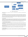
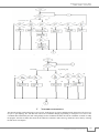
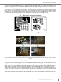
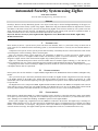
IJIRST –International Journal for Innovative Research in Science & Technology| Volume 2 | Issue 01 | June 2015
ISSN (online): 2349-6010
Automated Security System using ZigBee
Sneha Susan Abraham
Saveetha School Of Engineering, Saveetha University
Abstract
Nowadays, Wireless Security Monitoring System is one major research topic in field of Intelligent Buildings. In this paper, we
present a Wireless Home Security System Using ZigBee. Rather than using the traditional method to implement the real-time
surveillance of the home security; the system was developed using ZigBee for the wireless connectivity. The system can set the
alarm, Open the Door and Close the Door. The Hardware and Software and working of the system are explained in detail. A
number surveillance device can be connected for further improvement of the system.
Keywords: Wireless Security System, ZigBee Module, Digital Door Lock, Human Detection Module, ZigBee Relay
Module, Motion Sensor
_______________________________________________________________________________________________________
I.
INTRODUCTION
Home Security System is a system used to protect our home from intruders, theft i.e. system used to keep our home safe &
secure. There are two methods for home networking system:-(i) Conventional method i.e. wired.(ii) Un-conventional method i.e.
wirelesses.
Compared to wired system, wireless system provides more flexibility, extensibility and is free from construction works. In this
system design the wireless technology which is used is ZigBee.
This is an electronic locking system operated by the combination of digital key, security password or number code.To
implement this system we use ZigBee module which will furnish the purpose of wireless connectivity. ZigBee module is
designed to support wireless sensor network and as ZigBee Tag to identify the access objects.
ZigBee is a communication protocol which is based on IEEE 802.15.4 standard. ZigBee technology is a low data rate, low
power consumption, low cost; wireless networking protocol targeted towards automation and remote control applications.
Comparing to the other wireless technologies, ZigBee protocol is suitable for system environments, which require less power
consumption and low data rate requirement.
II.
SYSTEM OVERVIEW
In this system, there are four modules i.e. ZigBee Module, Digital Door Lock, HDM (human detection module) and ZigBee relay
module.
Once a person at the gate is detected by the human detection module, the ZigBee module of digital door lock sends a message
to the ZigBee module of the ZigBee relay module and checks whether the person has a ZigBee tag wirelessly. If a valid
identification code is taken from the ZigBee tag at the gate, digital door lock operates a motor connected with the locking system
to open the door.
The Digital Door Lock is composed of HDM, ZigBee Module and Microcontroller. The HDM is accomplished with a motion
sensor which is passive infrared type. The ZigBee module in the Digital Door Lock acts as the RFID reader which read ID
wirelessly. Microcontroller will check whether the received ID is correct or not, if it’s correct it will open the door.
III.
SYSTEM DESIGN
Radio frequency identification (RFID) is a common term that is used to describe a system that transmits a unique serial number
of an object or person wirelessly, using radio waves. RFID has long been used as an electronic key to control who has access to
office, buildings or area within office building. As RFID this system uses the ZigBee Module.
In this system, a ZigBee Tag, a digital door lock and a HDM are connected to the network. The ZigBee Tag is consisting of a
ZigBee module which acts as a key as well as the wireless communication device. The digital door lock is consisting of a ZigBee
module, a microcontroller, a LCD display, a Keypad and a motor. The HDM is accomplished through a motion sensor which
senses the motion in its range. The ZigBee module present in the Digital Door Lock act as communication device only.
All rights reserved by www.ijirst.org
296
Automated Security System using ZigBee
(IJIRST/ Volume 2 / Issue 01 / 042)
Fig. 1: Basic Block for implemented system
IV.
DESIGN IMPLEMENTATION
The system operation can be divided in to four parts: - normal, open/close, direct messaging, Tag registration/password
registration mode.
A. Normal Mode
Since the motion sensor is connected to the ADC of the microcontroller it is continuously being checked for any signal. So as
soon as there is motion detection through this motion sensor the microcontroller sends a signal to the ZigBee module through
UART. After getting a signal for motion sensor the ZigBee module tries to find a ZigBee tag in the person’s hand. If the ID
given by the Tag is correct it will ask for secret code if it matches with the previous stored code then the microcontroller will
move the motor to open the door otherwise it will run the buzzer. Even if there is no ZigBee tag in the persons hand it will run
the buzzer. The door will close after a delay automatically.
B. Direct Message
In this mode of working, the ID is send before the person is being detected through the motion sensor. This can be accomplished
through the use of the switch of the ZigBee module which is being used as the tag. As soon as the ID reaches the ZigBee module
in the digital door lock module, it will send the ID to the microcontroller which will compare it with the stored tag ID. If the Tag
matches with the stored ID then it ask for secret code, after that again it will match the code with the stored ones if correct then it
will move the motor to open the door, otherwise it will run the buzzer. The door will close automatically after a delay.
C. Tag Registration/Password Registration
This mode starts only when the switch for registration in the ZigBee module present in the digital door lock module is pressed.
After the reg. switch of the ZigBee module of digital door lock is pressed the ID should be send from Tag by pressing the switch
of reg. of the Tag.
As soon as the ID is received by the ZigBee module of the digital door lock it will send the ID to the microcontroller through
UART, which will check whether the ID is previously stored or not, if not then it will store the new ID and the corresponding
secret code, else if it is present then it will ask for secret code change, if it is pressed yes then it will ask for the new code, and it
will store the new code.
If the entered code length is more than four bit it will show error by sending a signal to the ZigBee module through UART which
will indicate the same by blinking the LED of the ZigBee Tag. The door will automatically close after a time delay.
D. Open/Close Mode
In this mode of working the door can be opened or closed by pressing this switch of the ZigBee module present at the digital
door lock. This is the facility given for the user to open the door from inside. It will open or close the door according to the
position of the door.
All rights reserved by www.ijirst.org
297
Automated Security System using ZigBee
(IJIRST/ Volume 2 / Issue 01 / 042)
Fig. 2: Flow chart for ZigBee Module of digital door lock
Fig. 3: Flow chart for the Tag
V.
NETWORK ESTABLISHMENT
The network topology used in this project is peer-to-peer. In this project we need to establish network between two devices so we
use peer to peer topology. We will make one node as the coordinator through programming, in workspace if we select as the
coordinator then automatically the stack setting changes for the coordinator and make the node as coordinator on which we dump
the program. After that we make other nodes as the end devices which are used as the Tag, which also can be done by selecting
the end device in workspace.
All rights reserved by www.ijirst.org
298
Automated Security System using ZigBee
(IJIRST/ Volume 2 / Issue 01 / 042)
This project is using minimum three nodes, one as the coordinator and another two as the end device. The coordinator will be
present at the digital door lock which will collect the data from end device which is Tag here. The end devices will act as Tag.
One tag will be already registered one and another will be unregistered ones.
As soon as a device is configured as the end-device, it will search for the coordinator by continuously sending the joining
request. Then as soon as an end device comes in contact with the coordinator it will send a joining request and if the coordinator
the capability to accept more end devices it will accept the request for joining and send a short address to the end device which is
also called as the network address. The devices can communicate as soon as the end device joins the network.
VI.
PCB LAYOUT AND SYSTEM SNAPSHOTS
Fig. 4: (a). PCB Layout for the main board, (b) PCB Layout for motor circuit
Fig. 5: (a). Setup in breadboard and testing in breadboard,(b) Main board of the system,(c)PCB for the motor circuit,(d) Total setup for the
system
VII.
RESULTS AND FUTURE WORK
This paper is concerned about designing an access monitoring and control system using ZigBee. The network between the two
ZigBee were established succefully. The modules were communicating properly and successfully. The full system was working
properly. This system is more advantageous than other methods because low power consumption which is achieved by the use of
ZigBee module. Since ZigBee is having low power consumption as well low data rate this system will consume low power.
This system is limited only to the access control and monitoring. This can be extended to make a full home security system in
which we can attach various sensors like temperature sensor, humidity sensor, smoke sensors to protect our home from hazards
like fire and to control the various devices in home like light, fan, A.C or devices according to the requirement. In this camera
facility can be provided to improve the security and to facilitate the user to interact with the outsider if they don’t have the Tag.
All rights reserved by www.ijirst.org
299
Automated Security System using ZigBee
(IJIRST/ Volume 2 / Issue 01 / 042)
REFERENCES
K.Hwang and J.W.Baek, “Wireless Access Monitoring and Control System based on Digital Door Lock,” IEEE Transactions on Consumer Electronics,
vol.53, no.54, Nov, 2007.
[2] A. Wheeler, “Commercial Application of Wireless Sensor Networks Using ZigBee,” Communication Magazine, IEEE, Apr 2007.
[3] P.Baronti, P.Pillai, V.W.C.Chook, S.Chessa,A.Gotta,Y.F.Hu, “Wireless Sensor Network:A Survey On the State of the art and the 802.15.4 and ZigBee
Standard “Science Direct,2007.
[4] F.L.Zucatto, C.A.Biscassi, F.Fidelix, S.Coutinho, M.L.Rocha, “ZigBee for Building Control Wireless Sensor Network,” IEEE Transactions on Consumer
Electronics,2007.
[5] Yeong Hyun Kwon,Dong Rycol Shin, “The Security Monitoring System Using IEEE 802.15.4 protocol and CMOS Image Sensor,” International
Conference On New Trends in Information and Service Science,2009.
[6] Dechuan Chen, Meifang Wang, “A Home Security ZigBee Network for Remote Monitoring Application,” ICWMMN 2006 Proceedings.
[7] Jiao Teng,Zhang Kun, Zhang Wen, Dong Xiuzhen,“Improve Communication Efficiency for the physiological Information Monitor System Based On
ZigBee,” IEEE Second International Symposium , 2009.
[8] Jun Hou, Chengdong Wu,Zhongjia Yuang,Jiyuan Tan,Qiaoqiao Wang,Yun Zhou,“Research of Intelligent Home Security Survelliance System Based On
ZigBee,”IEEE International Symposium on Intelligent Technology Application Workshops,2008.
[9] ZigBee Development Kit Manual, Vi Micros System Products.
[10] Vi-Sensor Module User Manual, Vi Micros System Products.
[1]
All rights reserved by www.ijirst.org
300