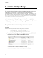
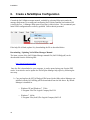
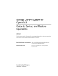
1
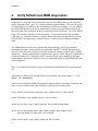
NuVAX 3400 VAX Replacement System Manual MVX-3400-OM Revision A MVX-3400-OM MNL_MVX3400_O1 Rev A Owner's Manual for the MVX-3400 VAX Replacement System Manual Document Number MNL_MVX-3400_O1 Revision A, February 2013 VMS is a trademark of Hewlett Packard Corporation. The material in this manual is for informational purposes only and is subject to change without notice. Contents 1 2 Installation......................................................................................................... 1 1. Unpacking the System ........................................................................................... 2 2. Verify NuVAX runs MDM diagnostics ................................................................ 4 3. Install the NuVAXplus Manager........................................................................... 6 4. Physical Disk Image Capture................................................................................. 8 5. Configure Option Module Address and Vectors ................................................... 9 6. Create a NuVAXplus Configuration ................................................................... 10 General Description........................................................................................ 13 Features............................................................................................................................ 13 Option Modules ............................................................................................................... 14 Specifications................................................................................................................... 14 System Unit................................................................................................................. 14 Ports ............................................................................................................................ 14 Accessories ................................................................................................................. 15 Compatibility .............................................................................................................. 15 Environmental............................................................................................................. 15 3 Maintenance .................................................................................................... 17 Air Filter .......................................................................................................................... 17 System Battery Replacement ........................................................................................... 18 CMOS BIOS .................................................................................................................... 20 Troubleshooting............................................................................................................... 21 Error Messages............................................................................................................ 21 i Contents Illustrations Figure 2-1: NuVAX System Front View ............................................................................... 13 Figure 3-1: Location of the Fan Filter.................................................................................... 17 Figure 3-2: Removing the Fan Filter...................................................................................... 18 Figure 3-3: Card Hold-down Bracket .................................................................................... 19 Figure 3-4: Motherboard........................................................................................................ 19 Tables Table 2-1: Qbus Option Modules .......................................................................................... 14 ii 1 Installation This chapter lists the steps involved in unpacking and setting up the NuVAX hardware and software. Installation consists of the following steps, each of which is described in this section or referred to another manual. Unpack the system Power up the system and verify it runs the MDM system diagnostic Install the NuVAXplus Manager Use NuVAXplus to capture your physical disk and create a virtual disk Set address and vectors for all option modules (I/O controllers) Create a NuVAXplus configuration file with physical and emulated I/O controllers 1 Installation 1. Unpacking the System The NuVAX system is shipped configured for your application with option modules installed. We recommend that two people perform the unpacking. Have a table or counter available. 2 A. Open the shipping container. B. Remove the box containing the MSC-3200 rack-mount slides and set aside for future use. C. Grasp the silver handles on each side of the chassis. D. Lift the chassis straight up out of the shipping container and place it on the table. Installation E. Cut the shrink wrap to release the accessories box from the rear of the chassis. F. Set the chassis on its side. Remove the foam packaging by lifting from the rear toward the handles at the front of the chassis. G. Turn chassis over onto the other side and remove second foam packaging. H. Open the drive bay at the front of the chassis and remove the foam cushioning. 3 Installation 2. Verify NuVAX runs MDM diagnostics Diagnostics to verify that NuVAX functions correctly and reliably allow you to selectively test the functions of the VAX CPU, memory and most option modules. The NuVAX system is shipped ready to run MDM on the configuration tested before shipping. You can validate the system still operates correctly by connecting one of the serial port cables located in the Accessory Box to the serial port on the rear panel of the NuVAX chassis. Use CAB-2009-18 if the VTxx console cable has a 9-pin connection. A 25-pin connection is also available, CAB-2010-18. Terminal emulators or simple character terminals can plug directly into the NuVAX DE9 COM port using a standard cross-over cable and do not require an adapter cable. The MDM diagnostic suite can be a useful tool when defining a NuVAX preventative maintenance program. Some modules are compatible with DEC’s MDM diagnostics and each NuVAX system disk contains a bootable virtual disk with the complete suite of MDM diagnostics. Custom modules may be supplied with Logical’s TREX diagnostic contained on a separate bootable CD. Consult the owner’s manual of each option module to determine what diagnostic method is available. Follow the instructions below to boot MDM and run the system diagnostic. Note: User input at the console is shown in bold print and the Return key is represented by [cr]. Apply power to the NuVAX and after about 30 seconds the VAX boot prompt, >>>, will appear. Type b mua0 [cr] After several seconds the MDM start-up banner appears and then it prompts for the date and time. It is not critical to set the date and time so just press the return key [cr]. Next it will ask for the mode of operation, type: 1 [cr] to select the ‘Menu Mode.’ At the ‘Main Menu’ type: 4 [cr] to enter the ‘Service Menu.’ At the ‘Service Menu’ type: 1 [cr] to enter the ‘Set test and message Menu.’ At the ‘Set test and message Menu’ type: 3 [cr] to enable ‘Stop testing on error.’ Next type 0 [cr], to return to the ‘Service Menu’. At the ‘Service Menu’ type: 3 [cr] to enable the ‘Device Menu.’ 4 Installation After all device drivers are loaded enter a [cr] and a device list is displayed. Review the list of devices to determine which you do not wish to include in the testing. It is best to disable the testing of all mass storage devices preventing the accidental destruction of important files. Type the number of a device to disable and a Return, then type: 1 [cr] to disable the testing. Next type 0 [cr], to return to the ‘Device Menu’. When you have completed device disabling, type: 0 [cr] this will return you to the ‘Service Menu’. At the ‘Service Menu’ type: 2 [cr] to start the system exerciser. The program will pause and wait for confirmation for any device that requires that a loop-back be installed. Type [cr] to confirm the request or type a Ctrl C to stop the process and return to the ‘Service Menu’. After loop-back confirmation completes, each device will perform a function test and then all devices will have their exercisers started and they will run concurrently until an error is encountered or testing is terminated by typing a Ctrl C. 5 Installation 3. Install the NuVAXplus Manager The NuVAXplus Manager (Manger) is a Windows desktop application that provides a userfriendly interface to configure the NuVAXplus software for a particular hardware configuration so that it accurately emulates the system it is replacing. The Manager can start and stop the NuVAXplus Emulator and reboot the system during the setup and configuration process. Upload/download capability of disk and tape images provide a convenient method of backing up or restoring emulated mass storage devices. A Help file document (NuVAXHelp.pdf) is provided on the CD with the NuVAXplus Manager. This file is also available from the Help menu of the program. The Help document explains how to use the Manager to create and manage configuration files to emulate a particular VAX system. The steps below describe how to install the Manager software and the Help files. Installation To install and use the NuVAXplus Manager the following are needed: PC or laptop with Windows XP or Windows 7 NuVAXplus Manager installation disc (MED0178CD) A. To install NuVAXplus Manager onto a PC or laptop computer, insert MED0178CD disc in the CD/DVD drive and then run the setup.exe program. The setup will walk you through the installation procedure. An icon on the computer’s desktop is added to open and use Manager 6 Installation B. Copy and replace the NuVAXhelp.pdf file located in the folder where Manager was installed with the NuVAXHelp.pdf file provided in the MED0178CD. By default Manager is installed in: Windows XP and Windows 7 32-bit: C:\Program Files\The Logical Company\NuVAX Windows 7 64-bit: C:\Program Files (0x86)\The Logical Company\NuVAX 7 Installation 4. Physical Disk Image Capture When you receive the NuVAX system, it does not contain an operating system. NuVAX can boot and run your VAX physical system disk or the disk contents can be moved to NuVAX’s internal disk for booting and operation. Moving the VMS physical disk image to a NuVAX virtual disk image is a complex process. Because each VAX system has a uniqic mass storage configuration there is not a user manual available for physical to virtual disk capture. We recommend that only qualified VARs and technical people trained by VARs attempt this procedure. 8 Installation 5. Configure Option Module Address and Vectors The option modules shipped in the NuVAX system are configured to the default addresses and vectors to run DEC diagnostics. If the interfaces in your VAX application are set to different addresses, any installed NuVAX option modules need to be set to match your application. Table 2-1 lists the DEC interfaces and their corresponding option modules. Note: The CCI-0008-A and CEI-2000-A option modules which are used to emulate serial async devices and Ethernet ports need to be declared in any configuration file but do not require vectors or addresses settings. A. Determine the addresses/vectors of the interfaces in your VAX system. B. Using the manual for your option module, set the address and vectors to match. The arrangement of physical option modules and the substitution of emulated disk, tape and network controller requires knowledge of DEC Qbus configuration rules and how they apply to a NuVAX containing both physical and emulated (virtual) I/O controllers. As with the physical disk capture, we recommend that only qualified VARs and technical people trained by VARs attempt this procedure. 9 Installation 6. Create a NuVAXplus Configuration Consult the NuVAXplus manager manual, available by selecting Help topics under the manager Help menu, for creating and configuring NuVAXplus emulator and emulated I/O (virtual) devices. A Manager Help menu screen shot is shown below. We recommend your initial VMS configuration be created by qualified VAR technical personnel. If the help file is blank, update it by downloading the file as described below. Downloading / Updating NuVAXPlus Manager Manual The latest version of the NuVAXplus Manager manual file (NuVAXHelp.pdf) can be downloaded from the following link: http://tinyurl.com/nuvaxhelp Once the file is downloaded to your computer, it can be opened using your favorite PDF reader. It can also be used to update the NuVAXplus Manager help topics by following the next step: Copy and replace the NUVAXhelp.pdf file located in the folder where Manager was installed with the NuVAXHep.pdf file downloaded from the link above. By default Manager is installed in: o Windows XP and Windows 7 32-bit: C:\Program Files\The Logical Company\NuVAX o Windows 7 64-bit: C:\Program Files (0x86)\The Logical Company\NuVAX 10 Installation 11 2 General Description The NuVAX is a complete hardware and software replacement for Digital Equipment Corporation’s VAX computer systems. Figure 2-1: NuVAX System Front View Features NuVAX systems offer a removable SATA system drive and an optional removable data drive. Support up to 64MB of VAX memory. Support Fast Ethernet adapters for 10/100 Mbps network connections to other systems using network protocols like DECnet and TCP/IP. Offer a choice of special DEC-style interfaces, or option modules. Other interfaces can be custom designed for your application. Support speeds of more than 24 times the VAX speed. 13 General Description Option Modules DEC Interface Option Module DRQ3B DQP-1500-AA Standard DQP-1500-AA Long Line DRV11 DQP-1300-AA DRV11-J DQP-1400-AA DRV11-WA DQP-1100-AA Standard DQP-1100-AB Long Line DEQNA, DELQA CEI-2000-A IEQ11-A DQP-3100-AA DHV11, DHQ11, DZQ11, CXY08 CCI-0008-AA External Unibus Support Adapter AQP-2303-AA, 2 KW11-K Table 2-1: Qbus Option Modules Specifications System Unit Physical Standard 4U rack-mount chassis (20” depth) Weight 13.6 kg (30 lbs) representative system Power 300 W @ 115/230 VAC, 50/60 Hz auto-sensing Drive Bays 2 cartridge-style Hard Drives Removable 80GB SATA drive; one system drive, one optional data drive Memory 512 MB, 64MB used for VAX memory Clock Optional KWV11-C or optional KW11-K emulation I/O Slots 5 available Ports Ethernet One port, reserved RS232 Serial Port COM1 Console, OPA0 Baud Rates 50, 75, 110, 134.5, 150, 300, 600, 1200, 1800, 2000, 2400, 4800, 7200, 9600, 19.2K, 38.4K bits/sec Data bits 5, 6, 7, 8 Stop bits 1, 1.5, 2 14 General Description Parity USB Odd, even, or no parity Not supported Accessories Mouse Not supported Keyboard, VGA Not supported Printer Supported LPV11 Compatibility Processors Supported MicroVAX II, MicroVAX 3300, 3400, 3500, 3600, 3800, 3900, and VAX Server 3600, 3900 Disks Emulated RQDX3, KDA50 Tapes Emulated TQK50, TQK70 Ethernet Emulated DEQNA, DELQA Environmental Operating Conditions: Temperature 10° to 40° C (50° to 104° F) Relative Humidity 20% to 80% non-condensing Storage Conditions: Temperature -40° to 60° C (-40° to 140° F) Relative Humidity 10% to 95% non-condensing 15 General Description 16 3 Maintenance This section provides basic maintenance information for your NuVAX system. The NuVAX system is designed for low-maintenance, trouble-free operation. Two areas require attention from time to time: Keep the air filter clean as described below, and minimize dust when possible. The CMOS battery on the motherboard lasts from 2-10 years depending upon operating temperature and the amount of time the system is turned off. Higher temperatures and long periods when the system is turned off shorten the battery life. We recommend that you replace the battery every two years as preventive maintenance. Air filter maintenance and battery replacement are described in the following sections. Air Filter Clean the fan air filter as often as necessary to prevent overheating due to reduced air movement. When reinstalling the air filter, make sure the filter material does not reduce the airflow within the chassis or overheating may become a problem. Generally, dust poses no danger to a computer, except for disk drives. Conductive dust, however, such as metal or carbon particles, can be problematic. To replace the air filter, refer to Figure 3-1 and do the following: Fan filter access door Figure 3-1: Location of the Fan Filter Operation and Maintenance 1) Remove power to the system. 2) To access the air filter, open the fan filter access door on the left side of the front panel by turning the quick-release screw counterclockwise. 3) Gently remove the filter from the inside of the fan filter access area. Lift the filter away from the chassis as shown in Figure 3-2. 4) Clean the air filter. The filter can be blown out or washed in soapy water. Make sure the filter is completely dry before reinstalling. 5) Close the fan filter access door on the front panel and tighten the quick-release screw. Figure 3-2: Removing the Fan Filter Note: Filters do not remove fumes or gases. Do not use the chassis in environments where airborne contaminants may damage the system. System Battery Replacement Replacing the system battery causes the CMOS BIOS data to be lost. Be prepared to attach a VGA monitor and PS2 keyboard to the NuVAX system to re-set the BIOS after the new battery is installed. To replace the battery: 18 1) Remove power to the system. 2) Remove the two black thumbscrews at the rear of the chassis. 3) Slide the chassis cover back and up to remove. 4) For easier access to the battery, remove the card hold-down bracket shown in Figure 1-4. Pull up on the black knob to release the bracket. Lift the bracket up to remove. Operation and Maintenance Chassis Front Figure 3-3: Card Hold-down Bracket 5) Locate the battery on the motherboard as shown in Figure 1-3. Battery Chassis Front Figure 3-4: Motherboard 6) To remove the battery, press the wire latch away from the battery until the battery pops out. Be careful when working next to the SATA cables. If you remove the cables for better access, be sure to mark them so that you can replace them in their original positions. 7) Install a new battery with ‘CR2032’ facing up. Dispose of the used battery according to the battery manufacturer’s instructions. 8) Replace the hold-down bracket and chassis cover and secure. 19 Operation and Maintenance When the battery is removed, CMOS BIOS settings are lost. The next section describes how to reset the BIOS. CMOS BIOS To re-set the BIOS settings, you need a VGA monitor and PS2 keyboard. Resetting the BIOS is a two-step process. First, you restore the platform manufacturer’s settings, and then you adjust the settings to tailor them for NuVAX. 1) Connect the monitor and keyboard to the back of the system chassis. a. Connect the PS2 keyboard to the lavender 6-pin mini-DIN connector. b. Connect the monitor to the 15-pin blue VGA connector and power on the monitor. 2) Power on the system and press ‘Delete’ to enter setup. 3) Use the arrow keys to navigate, ‘Enter’ to select and ‘Escape’ to exit and make the following changes to CMOS: o Load Optimized Defaults > Load Optimized Defaults (Y/N)? = Y o Standard CMOS Screen o o Advanced BIOS Features Screen First Boot Device = USB-FDD Second Boot Device = CDROM Third Boot Device = Hard Disk Boot Other Device = Disabled Boot Up Floppy Seek = Disabled Advanced Chipset Features Screen o AGP Aperture Size (MB) = 8 Integrated Peripherals Screen 20 Set time and date OnChip IDE Device > On-Chip Serial ATA = Enhanced Mode Operation and Maintenance Onboard Device > USB Keyboard Support = Enabled 4) Press ‘F10’ to save and exit Setup, press the ‘Y’ key to confirm. 5) Turn off power when the monitor re-displays. Troubleshooting If the NuVAX system does not boot properly, it may be due to a failed battery. Determine if this is the cause of the failure by attaching a VGA monitor and PS2 keyboard. If a new battery and BIOS settings does not resolve the problem, call your VAR for assistance. 1) Connect the monitor and keyboard to the back of the system chassis. a. Connect the PS2 keyboard to the lavender 6-pin mini-DIN connector. b. Connect the monitor to the 15-pin blue VGA connector and power on the monitor. 6) The BIOS runs a Power-On Self Test (POST). If it encounters an error, it displays: a. PRESS F1 TO CONTINUE, CTRL-ALT-ESC or DEL TO ENTER SETUP. 7) Press DEL to enter setup mode. Error Messages If the BIOS detects an error during the POST, one or more of the following messages may be displayed. CMOS BATTERY HAS FAILED The CMOS battery is no longer functional. It should be replaced. CMOS CHECKSUM ERROR Checksum of CMOS is incorrect. This can indicate that CMOS has become corrupt. This error may be caused by a weak battery. Check the battery and replace if necessary. Any other error messages indicate a failed motherboard. Call your VAR for assistance. 21 75 Gateway Blvd. Cottage Grove, Oregon 97424 USA http://www.logical-co.com The Logical Company Telephone: +1 541-942-3610 Fax: +1 541-942-3640 E-mail: [email protected]