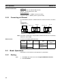
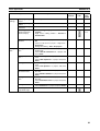
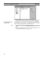
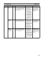
1
WS02-NCTC1-E CX-Position Operation Manual Produced July 2001 iv Notice: OMRON products are manufactured for use according to proper procedures by a qualified operator and only for the purposes described in this manual. The following conventions are used to indicate and classify precautions in this manual. Always heed the information provided with them. Failure to heed precautions can result in injury to people or damage to property. !DANGER !WARNING !Caution Indicates an imminently hazardous situation which, if not avoided, will result in death or serious injury. Indicates a potentially hazardous situation which, if not avoided, could result in death or serious injury. Indicates a potentially hazardous situation which, if not avoided, may result in minor or moderate injury, or property damage. OMRON Product References All OMRON products are capitalized in this manual. The word “Unit” is also capitalized when it refers to an OMRON product, regardless of whether or not it appears in the proper name of the product. The abbreviation “Ch,” which appears in some displays and on some OMRON products, often means “word” and is abbreviated “Wd” in documentation in this sense. The abbreviation “PC” means Programmable Controller and it is not used as the abbreviation for anything else. Visual Aids The following headings appear in the left column of the manual to help you locate different types of information. Note Indicates information of particular interest for efficient and convenient operation of the product. 1,2,3... 1. Indicates lists of one sort or another, such as procedures, checklists, etc. Notation In this manual, the following conventions are used to describe screen messages and mouse/keyboard operations. Names of menus and menu items are indicated in bold italic, e.g., the File Menu. Names of keys and buttons are indicated in bold (usually followed by “Key” or “Button”), e.g., Tab Key and OK Button. Dialog box and window names are indicated with capitalization, e.g., the Search Dialog Box. The levels of items in menu hierarchies are distinguished with back-slashes. For example, “Select File/ New” tells the reader to select New from the File Menu. The “+” sign is used to indicate that keys are pressed simultaneously. For example, “Press the Ctrl+S Keys” tells the reader to press the S Key while holding down the Ctrl Key. Copyrights Windows is a registered trademark of the Microsoft Corporation. VS-FlexGrid Pro is a product of Bunka Orient. Co., Ltd. (Copyright VideoSoft Corporation, 2000). Other system and product names used in this manual are the trademarks or registered trademark of the respective companies. v OMRON, 2001 All rights reserved. No part of this publication may be reproduced, stored in a retrieval system, or transmitted, in any form, or by any means, mechanical, electronic, photocopying, recording, or otherwise, without the prior written permission of OMRON. No patent liability is assumed with respect to the use of the information contained herein. Moreover, because OMRON is constantly striving to improve its high-quality products, the information contained in this manual is subject to change without notice. Every precaution has been taken in the preparation of this manual. Nevertheless, OMRON assumes no responsibility for errors or omissions. Neither is any liability assumed for damages resulting from the use of the information contained in this publication. vi TABLE OF CONTENTS PRECAUTIONS . . . . . . . . . . . . . . . . . . . . . . . . . . . . . . . . . . . xi 1 Intended Audience . . . . . . . . . . . . . . . . . . . . . . . . . . . . . . . . . . . . . . . . . . . . . . . . . . . . . . . . xii 2 General Precautions . . . . . . . . . . . . . . . . . . . . . . . . . . . . . . . . . . . . . . . . . . . . . . . . . . . . . . . xii 3 Safety Precautions. . . . . . . . . . . . . . . . . . . . . . . . . . . . . . . . . . . . . . . . . . . . . . . . . . . . . . . . . xii 4 Application Precautions . . . . . . . . . . . . . . . . . . . . . . . . . . . . . . . . . . . . . . . . . . . . . . . . . . . . xiii 5 Operating Environment Precautions . . . . . . . . . . . . . . . . . . . . . . . . . . . . . . . . . . . . . . . . . . . xiv SECTION 1 Overview . . . . . . . . . . . . . . . . . . . . . . . . . . . . . . . . . . . . . . . . . 1 1-1 Introduction . . . . . . . . . . . . . . . . . . . . . . . . . . . . . . . . . . . . . . . . . . . . . . . . . . . . . . . . . . . . . . 2 1-2 System Configuration . . . . . . . . . . . . . . . . . . . . . . . . . . . . . . . . . . . . . . . . . . . . . . . . . . . . . . 5 1-3 List of Functions . . . . . . . . . . . . . . . . . . . . . . . . . . . . . . . . . . . . . . . . . . . . . . . . . . . . . . . . . . 6 1-4 Comparison with SYSMAC-NCT . . . . . . . . . . . . . . . . . . . . . . . . . . . . . . . . . . . . . . . . . . . . 6 1-5 Basic Operating Procedure . . . . . . . . . . . . . . . . . . . . . . . . . . . . . . . . . . . . . . . . . . . . . . . . . . 7 SECTION 2 Setup and Basic Procedures . . . . . . . . . . . . . . . . . . . . . . . . . 9 2-1 Installation. . . . . . . . . . . . . . . . . . . . . . . . . . . . . . . . . . . . . . . . . . . . . . . . . . . . . . . . . . . . . . . 10 2-2 Connecting to a PC . . . . . . . . . . . . . . . . . . . . . . . . . . . . . . . . . . . . . . . . . . . . . . . . . . . . . . . . 13 2-3 Basic Operations . . . . . . . . . . . . . . . . . . . . . . . . . . . . . . . . . . . . . . . . . . . . . . . . . . . . . . . . . . 18 SECTION 3 Creating New Projects . . . . . . . . . . . . . . . . . . . . . . . . . . . . . . 37 3-1 Creating New Projects. . . . . . . . . . . . . . . . . . . . . . . . . . . . . . . . . . . . . . . . . . . . . . . . . . . . . . 38 3-2 Adding and Deleting PCs . . . . . . . . . . . . . . . . . . . . . . . . . . . . . . . . . . . . . . . . . . . . . . . . . . . 39 3-3 Adding and Deleting NC Units . . . . . . . . . . . . . . . . . . . . . . . . . . . . . . . . . . . . . . . . . . . . . . . 41 3-4 Automatic NC Unit Search . . . . . . . . . . . . . . . . . . . . . . . . . . . . . . . . . . . . . . . . . . . . . . . . . . 42 SECTION 4 Editing Settings . . . . . . . . . . . . . . . . . . . . . . . . . . . . . . . . . . . . 43 4-1 Overview . . . . . . . . . . . . . . . . . . . . . . . . . . . . . . . . . . . . . . . . . . . . . . . . . . . . . . . . . . . . . . . . 44 4-2 Setting Editing Screens . . . . . . . . . . . . . . . . . . . . . . . . . . . . . . . . . . . . . . . . . . . . . . . . . . . . . 47 4-3 Editing Parameter Settings . . . . . . . . . . . . . . . . . . . . . . . . . . . . . . . . . . . . . . . . . . . . . . . . . . 55 4-4 Editing Sequence Settings. . . . . . . . . . . . . . . . . . . . . . . . . . . . . . . . . . . . . . . . . . . . . . . . . . . 56 4-5 Editing Speed Settings . . . . . . . . . . . . . . . . . . . . . . . . . . . . . . . . . . . . . . . . . . . . . . . . . . . . . 58 4-6 Editing Acceleration/Deceleration Time Settings. . . . . . . . . . . . . . . . . . . . . . . . . . . . . . . . . 59 4-7 Editing Dwell Time Settings . . . . . . . . . . . . . . . . . . . . . . . . . . . . . . . . . . . . . . . . . . . . . . . . . 60 4-8 Editing Zone Settings . . . . . . . . . . . . . . . . . . . . . . . . . . . . . . . . . . . . . . . . . . . . . . . . . . . . . . 61 vii TABLE OF CONTENTS SECTION 5 Saving and Reading Projects . . . . . . . . . . . . . . . . . . . . . . . . . 63 5-1 Saving Projects . . . . . . . . . . . . . . . . . . . . . . . . . . . . . . . . . . . . . . . . . . . . . . . . . . . . . . . . . . . 64 5-2 Reading Projects . . . . . . . . . . . . . . . . . . . . . . . . . . . . . . . . . . . . . . . . . . . . . . . . . . . . . . . . . . 65 SECTION 6 Online Connection Default Configurations. . . . . . . . . . . . . 67 6-1 Default Configurations for Connecting Online. . . . . . . . . . . . . . . . . . . . . . . . . . . . . . . . . . . 68 6-2 FinsGateway Configuration and Startup . . . . . . . . . . . . . . . . . . . . . . . . . . . . . . . . . . . . . . . . 68 SECTION 7 Transferring and Verifying Data . . . . . . . . . . . . . . . . . . . . . 73 7-1 Downloading Data . . . . . . . . . . . . . . . . . . . . . . . . . . . . . . . . . . . . . . . . . . . . . . . . . . . . . . . . 74 7-2 Uploading Data . . . . . . . . . . . . . . . . . . . . . . . . . . . . . . . . . . . . . . . . . . . . . . . . . . . . . . . . . . . 75 7-3 Verifying Data . . . . . . . . . . . . . . . . . . . . . . . . . . . . . . . . . . . . . . . . . . . . . . . . . . . . . . . . . . . . 77 7-4 Writing Data to Flash Memory . . . . . . . . . . . . . . . . . . . . . . . . . . . . . . . . . . . . . . . . . . . . . . . 78 SECTION 8 Monitoring NCs . . . . . . . . . . . . . . . . . . . . . . . . . . . . . . . . . . . 81 8-1 Monitoring NCs . . . . . . . . . . . . . . . . . . . . . . . . . . . . . . . . . . . . . . . . . . . . . . . . . . . . . . . . . . 82 8-2 Multiple Unit Monitoring . . . . . . . . . . . . . . . . . . . . . . . . . . . . . . . . . . . . . . . . . . . . . . . . . . . 82 8-3 Operating Memory Area Monitoring . . . . . . . . . . . . . . . . . . . . . . . . . . . . . . . . . . . . . . . . . . 83 8-4 Operating Data Area Monitoring . . . . . . . . . . . . . . . . . . . . . . . . . . . . . . . . . . . . . . . . . . . . . 84 SECTION 9 Printing Data. . . . . . . . . . . . . . . . . . . . . . . . . . . . . . . . . . . . . . 87 9-1 Printing Data . . . . . . . . . . . . . . . . . . . . . . . . . . . . . . . . . . . . . . . . . . . . . . . . . . . . . . . . . . . . . 88 SECTION 10 Error Logs and Troubleshooting . . . . . . . . . . . . . . . . . . . . . 91 10-1 NC Unit Error Logs. . . . . . . . . . . . . . . . . . . . . . . . . . . . . . . . . . . . . . . . . . . . . . . . . . . . . . . . 92 10-2 Troubleshooting . . . . . . . . . . . . . . . . . . . . . . . . . . . . . . . . . . . . . . . . . . . . . . . . . . . . . . . . . . 108 Revision History . . . . . . . . . . . . . . . . . . . . . . . . . . . . . . . . . . . 111 viii About this Manual: This manual describes the specifications and operation of the WS02-NCTC1-E CX-Position software and includes the sections described below. The CX-Position runs on Windows 95, 98, 2000, or NT operating systems and is used to create data for and monitor the operation of the CS1W-NC and CJ1W-NC Position Control Units (referred to as NC Units in this manual). @@@ @@@ Please read this manual carefully and be sure you understand the information provided before attempting to install and operate CX-Position. Please read the following manuals carefully and be sure you understand the information provided before using a Position Control Unit. NC Unit model number Manual name Cat. No. CS1W-NC113/213/413/133/233/433 CS1W-NC113/213/413/133/233/433 W376 Position Control Units Operation Manual CJ1W-NC113/213/413/133/233/433 CJ1W-NC113/213/413/133/233/433 W397 Position Control Units Operation Manual Section 1 provides an overview of CX-Position, its functions, and the system configuration in which it is used. Section 2 provides information about CX-Position installation, connecting to the PC, and basic operating procedures Section 3 describes the procedures for creating new projects, as well as those for adding and deleting Programmable Controllers (PCs) and Position Control Units (NCs). Section 4 describes the procedures used to edit settings Section 5 provides information about saving and reading files. Section 6 provides information on default configurations for connecting online. Section 7 provides information on data transfer and verification operations between the CX-Position and NC Units, and about operations for writing data transferred to NC Units into the NC Unit flash memory. Section 8 provides information about monitoring NC Units. The NC Unit’s current positions, error codes, and status are displayed on the NC Monitor. Monitor Units are also available, displaying sequence numbers and current positions for up to four Units simultaneously. Operating memory area monitoring, operating data area monitoring, and NC Unit error logs can also be displayed. For details on NC error log display, refer to 10-1 NC Unit Error Logs. Section 9 provides information about printing data. Section 10 provides information about NC Unit error log displays and troubleshooting. !WARNING Failure to read and understand the information provided in this manual may result in per- sonal injury or death, damage to the product, or product failure. Please read each section in its entirety and be sure you understand the information provided in the section and related sections before attempting any of the procedures or operations given. ix PRECAUTIONS This section provides general precautions for using CX-Position and related devices. The information contained in this section is important for the safe and reliable application of CX-Position. You must read this section and understand the information contained before attempting to set up or operate the CX-Position. 1 2 3 4 5 Intended Audience . . . . . . . . . . . . . . . . . . . . . . . . . . . . . . . . . . . . . . . . . . . . . General Precautions . . . . . . . . . . . . . . . . . . . . . . . . . . . . . . . . . . . . . . . . . . . . Safety Precautions. . . . . . . . . . . . . . . . . . . . . . . . . . . . . . . . . . . . . . . . . . . . . . Application Precautions . . . . . . . . . . . . . . . . . . . . . . . . . . . . . . . . . . . . . . . . . Operating Environment Precautions . . . . . . . . . . . . . . . . . . . . . . . . . . . . . . . . xii xii xii xiii xiv xi 1 Intended Audience 1 Intended Audience This manual is intended for the following personnel, who must also have knowledge of electrical systems (an electrical engineer or the equivalent). • Personnel in charge of installing FA systems. • Personnel in charge of designing FA systems. • Personnel in charge of managing FA systems and facilities. 2 General Precautions The user must operate the product according to the performance specifications described in the operation manuals. Before using the product under conditions which are not described in the manual or applying the product to nuclear control systems, railroad systems, aviation systems, vehicles, combustion systems, medical equipment, amusement machines, safety equipment, and other systems, machines, and equipment that may have a serious influence on lives and property if used improperly, consult your OMRON representative. Make sure that the ratings and performance characteristics of the product are sufficient for the systems, machines, and equipment, and be sure to provide the systems, machines, and equipment with double safety mechanisms. This manual provides information for using CX-Position. Be sure to read this manual before attempting to use CX-Position and keep this manual close at hand for reference during operation. !WARNING 3 Safety Precautions !WARNING !WARNING !Caution !Caution !Caution xii It is extremely important that CX-Position and related devices be used for the specified purpose and under the specified conditions, especially in applications that can directly or indirectly affect human life. You must consult with your OMRON representative before applying CX-Position and related devices to the above mentioned applications. Never attempt to disassemble any Units while power is being supplied. Doing so may result in serious electric shock. Never touch any of the terminals while power is being supplied. Doing so may result in serious electric shock. Save parameters and other data to flash memory after transferring them to the Position Control Unit (referred to as NC Units in this manual). If parameters and other data are not saved to flash memory, data will return to their previous values the next time power is turned ON, possibly resulting in Unit malfunction. Confirm the safety of the destination node before transferring parameters or other data to the node. Transferring parameters or other data without confirming safety may result in injury. Do not save data to flash memory during memory operation or while the motor is running. Doing so may result in unexpected operation. 4 Application Precautions 4 Application Precautions !Caution Observe the following precautions when using CX-Position. • Confirm the unit number before transferring parameters and other data to an NC Unit. • Confirm that set parameters and data operate properly before using in actual operation. • When the settings of the following parameters have been changed, they must be transferred to the NC Unit and written to flash memory, and then the NC Unit must be turned OFF and back ON, or restarted as a Special I/ O Unit, to enable using the new settings. • Output pulse selection • Limit input signal type • Origin proximity input signal type • Origin input signal type • Emergency stop input function • No-origin specification • Operating mode selection • Origin search operation • Origin detection method • Origin search direction • Do not turn OFF the power to an NC Unit while writing to flash memory. Doing so may damage flash memory. • Confirm that no adverse effect will occur in the system before attempting any of the following. Not doing so may result in unexpected operation. • Changing the operating mode of the PC. • Changing the present value of any word or any set value in memory. • Force-setting/force-resetting any bit in memory. • Do not turn OFF the power to the computer while installing or uninstalling CX-Position. Doing so may corrupt computer data. xiii Operating Environment Precautions 5 5 Operating Environment Precautions !Caution !Caution Perform installation properly, according to the procedures described in this manual. Do not install in the following locations: • Locations subject to direct sunlight. • Locations subject to temperatures or humidity outside the range specified in the specifications. • Locations subject to condensation as the result of severe changes in temperature. • Locations subject to corrosive or flammable gases. • Locations subject to dust (especially iron dust) or salts. • Locations subject to exposure to water, oil, or chemicals. • Locations subject to shock or vibration. !Caution Take appropriate and sufficient countermeasures when installing in the following locations: • Locations subject to static electricity or other forms of noise. • Locations subject to strong electromagnetic fields. • Locations subject to possible exposure to radioactivity. • Locations close to power supplies. xiv SECTION 1 Overview This section provides an overview of CX-Position, its functions, and the system configuration in which it is used. 1-1 Introduction . . . . . . . . . . . . . . . . . . . . . . . . . . . . . . . . . . . . . . . . . . . . . . . . . . . 2 1-1-1 What Is CX-Position? . . . . . . . . . . . . . . . . . . . . . . . . . . . . . . . . . . . . 2 1-1-2 Applicable NC Units. . . . . . . . . . . . . . . . . . . . . . . . . . . . . . . . . . . . . 2 1-1-3 Features. . . . . . . . . . . . . . . . . . . . . . . . . . . . . . . . . . . . . . . . . . . . . . . 2 1-1-4 Applicable Computers . . . . . . . . . . . . . . . . . . . . . . . . . . . . . . . . . . . 3 1-1-5 CX-Position Data . . . . . . . . . . . . . . . . . . . . . . . . . . . . . . . . . . . . . . . 3 1-1-6 Software Structure . . . . . . . . . . . . . . . . . . . . . . . . . . . . . . . . . . . . . . 3 1-1-7 Checking the Package. . . . . . . . . . . . . . . . . . . . . . . . . . . . . . . . . . . . 4 1-2 System Configuration . . . . . . . . . . . . . . . . . . . . . . . . . . . . . . . . . . . . . . . . . . . 5 1-3 List of Functions . . . . . . . . . . . . . . . . . . . . . . . . . . . . . . . . . . . . . . . . . . . . . . . 6 1-4 Comparison with SYSMAC-NCT . . . . . . . . . . . . . . . . . . . . . . . . . . . . . . . . . 6 1-5 Basic Operating Procedure . . . . . . . . . . . . . . . . . . . . . . . . . . . . . . . . . . . . . . . 7 1 Section 1-1 Introduction 1-1 1-1-1 Introduction What Is CX-Position? The CX-Position is a software package that enables the setting, transfer, storage, and printing of data used with Position Control Units (referred to as NC Units in this manual), as well as monitoring of NC Unit operating status. The CX-Position runs on a Windows 95, 98, 2000, or NT operating system. Computer with Windows operating system NC Unit Data (e.g., parameter data, position data) used with the NC Unit is set and transferred. The NC Unit’s operating status (e.g., present position, I/O status, and error display) is monitored. 1-1-2 Applicable NC Units CX-Position can be used with the following NC Units. NC Unit model number CS1W-NC113/133/213/233/413/433 CS1W-NC113/133/213/233/413/433 PC series CS Series CJ Series Note For details on the system configuration, refer to 1-2 System Configuration. 1-1-3 Features Data Management and Editing in Project Units 2 The CX-Position enables data for several NC Units (96 NC Units max. per PC) on several PCs (1,000 max.) to be handled as 1 project. Data is displayed in tree format with parameter data, sequence data, speed data, acceleration/ deceleration data, dwell times, and zone data displayed under the corresponding NC Unit, NC Units displayed under the corresponding PC, and PCs displayed under the corresponding project. Section 1-1 Introduction Individual Copying and Moving of NC Unit Data NC Unit data, such as parameters, sequences, and speeds, can be moved or copied (overwritten) between PCs in the project tree. This feature enables editing and re-use of the same or similar data with other PCs or NC Units. Communications with NC Units via Networks The CX-Position communicates with NC Units using FinsGateway. Depending on the type of FinsGateway driver used, online operations (e.g., monitoring and transfer/verification of parameter and sequence data) are possible via Host Link (SYSWAY-CV) or Ethernet. Automatic Project Generation The CX-Position can read information about the NC Units mounted on a PC connected online, and automatically create a project based on this information. (CX-Position can also upload actual data from NC Units and use it in the project.) This feature eliminates the necessity of creating a new project offline before going online. Importing SYSMAC-NCT Data Data created for the C200HW-NC using the SYSMAC-NCT (with “.ncm” file extension) can be imported and used as data for the CS1W-NC or CJS1W-NC . 1-1-4 @@@ @@@ @@@ Applicable Computers The CX-Position can be used on computers that satisfy the following conditions. Item 1-1-5 Requirement Computer IBM PC/AT or compatible Operating system Windows 95, 98, 2000, or NT 4.0 CPU Pentium 100 Mhz or higher Memory 32 Mbytes min. Hard disk drive 100 Mbytes min. CD-ROM drive 1 min. Monitor SVGA (800 × 600 pixels) min. CX-Position Data The CX-Position is used to make project files with the configuration shown below. The file extension for project files is “.nci”. Project file (“.nci”) PC NC NC NC NC PC NC 1,000 PCs max. Parameter data Sequence data Speed data Acceleration/deceleration data Dwell times Zone data 96 Units max. (See note.) One “PC” contains the data for 1 PC (CPU Unit). One project file can contain up to 1,000 PCs. One “NC” contains all the data for 1 NC Unit. 1-1-6 Note The number of NC Units is restricted by the number of allocated unit numbers and the current consumption. Software Structure The CX-Position exchanges data (online communications) with NC Units via FinsGateway. In order to execute functions online, either FinsGateway Version 2 Embedded Edition or FinsGateway Version 3 Embedded Edition must be installed on the same computer as CX-Position. FinsGateway Version 3 Embedded Edition is included on the setup disk. 3 Section 1-1 Introduction The communications method (i.e., the type of network) depends on the FinsGateway driver used. For example, to connect using Host Link (SYSWAY-CV) via the RS-232C port, use the FinsGateway Serial Unit driver. CX-Position FinsGateway Serial Unit driver ETN_UNIT driver Host Link (SYSWAY-CV) (peripheral port or RS-232C port) Ethernet Note The CX-Position can be used with a Serial Unit driver or via Ethernet only. 1-1-7 Checking the Package After purchase, confirm that the contents of the package are as described below. Model Number Confirm that the following details are correct. Product name CX-Position CX-Position Package 4 Model number WS02-NCTC1-E Setup disk CD-ROM The CX-Position software package consists of the following items. Confirm that accessories are provided. Setup disk (CD-ROM) 1 Operation manual (this manual) 1 Software Licence Agreement/User Registration Card 1 Address label 1 Section 1-2 System Configuration System Configuration The system configuration for the NC Units is given below with the CS1WNC413/433 used as a representative example. The CS1W-NC213/233 and CS1W-NC113/133 are used for control of 2 axes and 1 axis respectively. CPU Unit NC Unit (CS1W-NC413/433) (CS1 Series) Power Supply Unit CX-Programmer Creation and transfer of ladder programs, monitoring, file management, etc. Host Link Host Link 20 21 0 22 1 23 2 24 3 25 4 26 5 28 29 8 30 9 31 10 32 11 33 12 34 13 35 36 14 19 19 18 39 17 38 16 37 15 36 37 38 18 39 17 CX-Position Creation and transfer of data, NC Unit monitoring, file management, etc. External inputs 27 6 28 29 8 30 9 31 10 32 11 33 12 34 13 35 14 15 16 2 3 Dedicated terminal block 7 1 23 5 4 26 25 24 External inputs 27 6 0 22 21 20 Dedicated terminal block 7 1-2 CCW limit input CW limit input Origin input Origin proximity input Emergency stop input Interrupt input CCW limit input CW limit input Origin input Origin proximity input Emergency stop input Interrupt input Interface power supply (24 V) Interface power supply (24 V) Stepping motor drivers Servomotor drivers Stepping motor drivers or Stepping motors Note Servomotor driver or Servomotors Stepping motors Servomotors 1. Special cables are available to connect OMRON U-series Drivers, W-series Drivers, or Smart Step A-series Drivers. Cables made by the user can also be used. 2. Special cables are available for connections to special terminal blocks. Cables made by the user can also be used. 3. A battery for data backup is required when using an absolute encoder. 5 Section 1-3 List of Functions 1-3 List of Functions Group Editing projects Editing NC Unit data Function Details Page Create project Used to create project files (“.nci”). Create PC Used to specify a PC model and add PC data to a project. page 38 page 39 Create NC Unit Used to specify an NC Unit model and add NC Unit data to a PC in a project. page 41 Edit PC/NC Unit Used to perform editing for a project, such as making property set- page 41 tings for or deleting PCs or NC Units, cutting, copying, or pasting NC Units, pasting NC Unit data, and drag-and-drop. Edit Used to edit the NC Unit Parameter data data shown on the right. Sequence data page 55 page 56 Speed data page 58 Acceleration/deceleration time data page 59 Dwell time data page 60 Zone data page 61 Save Used to save all the data in a project as a project file (“.nci”). page 64 Load Used to read a project file (“.nci”) to a project. page 65 Importing NCT data files Import Used to import data files created with SYSMAC-NCT to CX-Position projects. page 65 Online Download/upload/verify Used to download, upload, or verify data. page 74, page 75, page 77 Saving and loading project files Flash memory write Used to write data to flash memory. page 78 Monitor Used to display the sequence number, present position, I/O status, and error code for an NC Unit. page 82 Monitor Units Used to display the sequence numbers, present positions, I/O sta- page 82 tuses, and error codes for 4 NC Units. Automatic project setting Used to read information about the NC Units mounted on a speci- page 42, page 76 fied PC connected online, and creates a project tree based on this. If the data upload check box is turned ON, the data for all NC Units on the specified PC is read and included in the project. 1-4 Operating memory area monitor Used to monitor the CPU Unit’s operating memory area. page 83 Operating data area monitor Used to monitor the CPU Unit’s operating data area. page 84 NC Unit error log monitor Used to monitor items (20 max. per NC Unit) in NC Unit error logs. page 92 Comparison with SYSMAC-NCT Item @@@ @@@ CX-Position SYSMAC-NCT @@@ @@@ NC Unit CS1W-NC CJ1W-NC Created files Project files (“.nci”) created with the data from more than Data files (C200HW-NC: “.ncm”; C5001 NC Unit mounted on more than 1 PC (1,000 max.) NC: “.ncl”) created with the data from 1 NC Unit Managing and editing using projects Supported Within a project, data can be moved or copied (see note) in units of NC Units using “drag-and-drop” and “copyand-paste” operations. (Data can be moved or copied within the same PC or between PCs.) Note The data at the NC Unit to which data is copied is overwritten. Icons are not copied along with the data. 6 C200HW-NC C500-NC Not supported All data is handled together. (Moving and copying in units of NC Units is not possible.) Section 1-5 Basic Operating Procedure Item CX-Position SYSMAC-NCT Method for connecting to PC • Connected to the RS-232C port on the CPU Unit or a Connected to the RS-232C port on the Serial Communications Board/Unit using an RS-232C CPU Unit using an RS-232C cable. cable. • Connected to the peripheral port on the CPU Unit using a peripheral cable, or via Ethernet. Networks for connection to PC Select from the following using the FinsGateway driver: • Host Link (SYSWAY-CV or RS-232C) • Ethernet (via an Ethernet board) Host Link (RS-232C) only Decimal/binary display selection Supported. Not supported (decimal only). Changing display font size Supported. Not supported. NC Unit error log dis- Supported. play Not supported. 1-5 Basic Operating Procedure A basic outline of the procedures required to install the CX-Position and FinsGateway, create data, transfer it to the NC Units, and use in actual operation is given below. 7 Section 1-5 Basic Operating Procedure Install CX-Position. Refer to 2-1 Installation. Install FinsGateway. Refer to 2-1 Installation. Connect to the CPU Unit’s built-in RS-232C port. Refer to 2-2 Connecting to a PC. Start CX-Position. Refer to 2-3 Basic Operations. Create a new project. Offline operations Add PCs to the project Add NC Units to the PCs in the project. Create/edit NC Unit data. Save the project. Initialize the NC Units and CPU Unit. Online operations Make communications settings for FinsGateway and start up communications. Download data to the NC Units. Refer to 3-2 Adding and Deleting PCs. Refer to 3-3 Adding and Deleting NC Units. Refer to SECTION 4 Editing Settings. Refer to SECTION 5 Saving and Reading Projects. Refer to 6-1 Default Configurations for Connecting Online. Refer to 6-2 FinsGateway Configuration and Startup. The Network Address and Node Address in Network Type must be set to the settings used in FinsGateway. Network Address: Set the same setting as in Network Number under Network in FinsGateway. (Default setting for Host Link connection: 0.) Node Address: Set the same setting as in Node under Nodes in FinsGateway. (Default setting for Host Link connection: 240.) Refer to 7-1 Downloading Data. Refer to 7-4 Writing Data to Flash Memory. Write data to the flash memory in NC Units. Perform positioning with the NC Units. Monitor the NC Units. 8 Refer to 3-1 Creating New Projects. Refer to the Operation Manual for the NC Unit. Refer to SECTION 8 Monitoring NCs. SECTION 2 Setup and Basic Procedures This section provides information about CX-Position installation, connecting to the PC, and basic operating procedures. 2-1 2-2 2-3 Installation. . . . . . . . . . . . . . . . . . . . . . . . . . . . . . . . . . . . . . . . . . . . . . . . . . . . 10 2-1-1 Installing CX-Position and FinsGateway . . . . . . . . . . . . . . . . . . . . . 10 2-1-2 Uninstalling CX-Position or FinsGateway . . . . . . . . . . . . . . . . . . . . 13 Connecting to a PC . . . . . . . . . . . . . . . . . . . . . . . . . . . . . . . . . . . . . . . . . . . . . 13 2-2-1 Connecting via Host Link (SYSWAY-CV). . . . . . . . . . . . . . . . . . . . 14 2-2-2 Connecting via Ethernet . . . . . . . . . . . . . . . . . . . . . . . . . . . . . . . . . . 18 Basic Operations . . . . . . . . . . . . . . . . . . . . . . . . . . . . . . . . . . . . . . . . . . . . . . . 18 2-3-1 Starting . . . . . . . . . . . . . . . . . . . . . . . . . . . . . . . . . . . . . . . . . . . . . . . 18 2-3-2 Quitting . . . . . . . . . . . . . . . . . . . . . . . . . . . . . . . . . . . . . . . . . . . . . . . 19 2-3-3 Basic Window . . . . . . . . . . . . . . . . . . . . . . . . . . . . . . . . . . . . . . . . . . 20 2-3-4 Displaying Menus. . . . . . . . . . . . . . . . . . . . . . . . . . . . . . . . . . . . . . . 21 2-3-5 Moving and Copying NC Unit Data . . . . . . . . . . . . . . . . . . . . . . . . . 22 2-3-6 Main Menus . . . . . . . . . . . . . . . . . . . . . . . . . . . . . . . . . . . . . . . . . . . 24 2-3-7 Main Menu Items . . . . . . . . . . . . . . . . . . . . . . . . . . . . . . . . . . . . . . . 25 2-3-8 Operations Listed by Purpose . . . . . . . . . . . . . . . . . . . . . . . . . . . . . . 28 2-3-9 Toolbar . . . . . . . . . . . . . . . . . . . . . . . . . . . . . . . . . . . . . . . . . . . . . . . 31 2-3-10 Status Bar . . . . . . . . . . . . . . . . . . . . . . . . . . . . . . . . . . . . . . . . . . . . . 31 2-3-11 Option Settings . . . . . . . . . . . . . . . . . . . . . . . . . . . . . . . . . . . . . . . . . 31 2-3-12 View Settings . . . . . . . . . . . . . . . . . . . . . . . . . . . . . . . . . . . . . . . . . . 32 2-3-13 Setting the Network Type . . . . . . . . . . . . . . . . . . . . . . . . . . . . . . . . . 33 2-3-14 Help. . . . . . . . . . . . . . . . . . . . . . . . . . . . . . . . . . . . . . . . . . . . . . . . . . 33 9 Section 2-1 Installation 2-1 Installation To use the CX-Position, the following software must be installed on the same computer. • CX-Position • FinsGateway Version 3 Embedded Edition Note 1. FinsGateway Version 3 Embedded Edition is included with the CX-Position package. 2. If FinsGateway Version 3 Embedded Edition is not installed, CX-Position can be started up, but online operations are not possible. Only offline operations can be performed. 3. CX-Position can also be used with FinsGateway Version 2. 4. For details on preparation required before installing FinsGateway, refer to the FinsGateway User’s Manual (PDF data). 2-1-1 Installing CX-Position and FinsGateway Use the following procedure to install CX-Position, FinsGateway, and the Serial Unit driver or Ethernet driver. 1,2,3... 1. Insert the CD-ROM into the computer’s CD-ROM drive. After a dialog box indicating that setup preparation is taking place has been displayed, the following window will be displayed. 2. Click Next. The Software Licence Agreement Dialog Box will be displayed. 3. Click Next and input the licence number (as printed on the Software Licence Agreement/User Registration Card). The Destination Location Dia- 10 Section 2-1 Installation log Box will be displayed. 4. Specify the drive and folder to which CX-Position is to be installed. The default destination is C:\Program Files\OMRON\CX-Position. No changes are required to install in the folder that is displayed. To install in a different folder, click Browse and select the desired drive and folder. 5. Click Next. The Program Folder Dialog Box will be displayed. Select the desired program folder. The default program folder is CX-Position. 6. Click Next. The CX-Position Setup Dialog Box will be displayed and installation will start. Next, the following dialog box will be displayed to confirm whether FinsGateway installation is necessary. 7. Click Yes. (If FinsGateway is already installed, click No.) The FinsGateway and Serial Unit Driver Installation Window will be displayed. 11 Section 2-1 Installation 8. Click Next. The FinsGateway and ETN_UNIT Driver Installation Window will be displayed. 9. Click Next. The User Registration Dialog Box will be displayed. 10. Enter your name and organization, and click OK. A confirmation will be displayed. 11. Click Next. The Destination Location Dialog Box will be displayed. 12. Specify the drive and folder to which FinsGateway is to be installed. The default destination is C:\Program Files\OMRON\FinsServer95. No changes are required to install in the folder that is displayed. To install in a different folder, click Browse and select the desired drive and folder. 13. Click Next. The Program Folder Dialog Box will be displayed. Select the desired program folder. The default program folder is FinsGateway. No changes are required to install in the folder that is displayed. To install in a different folder, click Browse and select the desired drive and folder. 14. Click Next. FinsGateway has been installed. 15. Click Finish. Note Do not turn OFF or reset the power to the computer during installation. Computer data may be damaged. 12 Section 2-2 Connecting to a PC 2-1-2 Uninstalling CX-Position or FinsGateway Uninstalling CX-Position 1,2,3... Use the following procedure to remove CX-Position from the computer. 1. Click Start on the task bar and move the cursor to Settings. 2. Select Control Panel. 3. Double-click the Add/Remove Programs Icon. 4. The Add/Remove Programs Properties Dialog Box will be displayed. Select CX-Position from the Install/Uninstall List and click the Add/Remove Button. 5. Click OK in the confirmation dialog box. CX-Position will be removed from the computer. Uninstalling FinsGateway 1,2,3... Use the following procedure to remove FinsGateway from the computer. 1. Click the Start on the task bar and move the cursor to Settings. 2. Select Control Panel. 3. Double-click the Add/Remove Programs Icon. 4. The Add/Remove Programs Properties Dialog Box will be displayed. Select OMRON FinsGateway + SerialUnit Embedded Edition from the Install/Uninstall List and click the Add/Remove Button. 5. Click OK in the confirmation dialog box. FinsGateway will be removed from the computer. Note Do not attempt to uninstall CX-Position or FinsGateway Version 3 when they are running. The uninstall operation may not be completed successfully. 2-2 Connecting to a PC Note If OMRON Support Software that communicates using CX-Server (e.g., CXProgrammer, CX-Protocol, or CX-Motion) or an application that uses a special serial driver is connected online, it is not possible to perform online operations from CX-Position using the same COM port. Quit online connection for the OMRON Support Software that communicates using CX-Server (e.g., CXProgrammer, CX-Protocol, or CX-Motion) or the application that uses a special serial driver, and then re-attempt online operations from CX-Position after starting up FinsGateway’s Serial Unit servicing. CX-Position can be connected to the PC using any of the following methods. Network type Computer port FinsGateway communications driver Host Link (SYSWAY- RS-232C port CV) (See note.) Serial Unit driver Ethernet Ethernet driver Ethernet port (or built-in port) Note Connection is also possible to PCs on Controller Link, SYSMAC LINK, or Ethernet networks via Host Link (using the PC’s gateway functions). Any FinsGateway Version 2 driver can be used. FinsGateway Version 3 Embedded Edition is included with CX-Position. The following explanation is for when FinsGateway Version 3 Embedded Edition is used. Use the following procedure to start up the FinsGateway communications driver. For details, refer to 6-2 FinsGateway Configuration and Startup. 13 Section 2-2 Connecting to a PC 1,2,3... 1. Select Programs/FinsGateway/FinsGateway Settings from the Start Menu. 2. Select the desired communications driver under Driver under Network on the Basic Tab Page, click Properties, and make the required settings (COM port used, communications protocol (see note), communications conditions, etc.). Note For example, select SYSWAY-CV to connect via Host Link (SYSWAY-CV). 3. Select the desired communications driver (service) under Services on the Basic Tab Page, and click the Start Button. 2-2-1 Connecting via Host Link (SYSWAY-CV) To connect via Host Link, use FinsGateway Version 3’s Serial Unit driver. Use Host Link (SYSWAY-CV) to connect to the PC’s peripheral port or RS-232C port. Connection Method Computer Connection to RS-232C port Connection to peripheral port 9 pin, male IBM PC/AT or compatible 9 pin, male 9 pin, female PC-9801 BX NEC Peripheral port 10 pin, female CS1W-CN118 (0.1 m) (See note.) CS1W-CN226 (2.0 m) CS1W-CN626 (6.0 m) CS1W-CN118 (See note.) CS1W-CN226 CS1W-CN626 9 pin, female 9 pin, male PC-9801 BX RS-232C port 9 pin, female NEC XW2Z-200S-CV/200S-V (2.0 m) XW2Z-500S-CV/500S-V (5.0 m) XW2Z-200S-CV/200S-V XW2Z-500S-CV/500S-V 10 pin 9 pin, female 9 pin, male Note Use the CS1W-CN118 to connect to the peripheral port of the CPU Unit using one of the RS-232C cables shown on the right (XW2Z) in the way shown below. @@@@ @@ Peripheral port PC-9801 BX NEC RS-232C cable CS1W-CN118 Note With CS/CJ-series PCs, it is also possible to connect to ports on Serial Communications Units/Boards. In this case, connection can be made by Host Link only. 14 Section 2-2 Connecting to a PC Connecting Cables Unit CPU Unit Port on Unit Computer IBM PC/AT Built-in peripheral or compatible port Port on computer D-SUB, 9pin, male FinsGateway communications driver Serial Unit Protocol (serial communications mode) Model number SYSWAY-CV CS1WCN226 2.0 m CS1WCN626 6.0 m XW2Z2m 200S-CV Built-in RS-232C port (D-SUB, 9-pin, female) Serial Communications Board/Unit Length XW2Z5m 500S-CV XW2Z2m 200S-CV RS-232C port (D-SUB, 9-pin, female) XW2Z5m 500S-CV Remarks --- Uses anti-static connector Uses anti-static connector Note When connecting the connectors of the above cables to the PC’s RS-232C port, discharge any static build-up (e.g., by touching a grounded metal object) before touching the connectors. Although XW2ZS-CV Cables use the anti-static XM2S-0911-E Connector Hood (thus reducing the possibility of static build-up), be sure to discharge any static as a safety precaution. @@@ Other Connection Methods Connecting RS-232C Cable to Peripheral Port Unit Port on Unit CPU Unit Built-in peripheral port Computer IBM PC/AT or compatible The following connection methods can be used when connecting an RS-232C cable to the peripheral port. Port on computer FinsGateway communications driver Protocol (serial communications mode) D-Sub, 9pin, male Serial Unit SYSWAY-CV Model number CS1WCN118 + XW2Z200S-CV/ 500-CV Length 0.1 m (2 m or 5 m) Unit CPU Unit Port on Unit The XW2ZS-CV uses an anti-static connector. @@@ --- CS1WCN118 + XW2Z200S-V/ 500-V Connecting CQM1-CIF01/02 to Peripheral Port Remarks The following connection method can be used when connecting the conventional CQM1-CIF01/02 Cable to the peripheral port. Computer Port on computer IBM PC/AT D-Sub, 9Built-in pin, male peripheral or compatible port FinsGateway communications driver Serial Unit Protocol (serial communications mode) SYSWAY-CV Model number CS1WCN114 + CQM1CIF02 Length 0.5 m + 3.3 m Remarks --- 15 Section 2-2 Connecting to a PC Connecting a Computer with an RS-232C Cable Unit CPU Unit Serial Communications Board/ Unit Port on Unit The following connection method can be used when connecting an IBM PC/ AT or compatible computer using an RS-232C cable. Computer Port on computer FinsGateway communications driver Built-in RS- IBM PC/AT D-SUB, 9- Serial Unit pin, male 232C port or (D-SUB, 9- compatible pin, female) Protocol (serial communications mode) SYSWAY-CV RS-232C port (DSUB, 9-pin, male) Model number Length Remarks XW2Z200S-V 2m --- XW2Z500S-V 5m XW2Z200S-V 2m XW2Z500S-V 5m Making an RS-232C Cable For connections with an RS-232C cable, either purchase one of the cables listed above, or make a cable using the connection method and components given below. Connector Pin Arrangement The pin arrangement for the CPU Unit connector is shown below. Pin number Signal abbreviation Signal name 1 FG Frame ground --- 2 SD (TXD) Send data Output 3 RD (RXD) Receive data Input 4 RS (RTS) Request to send Output 5 CS (CTS) Clear to send Input 6 5V Power supply --- 7 DR (DSR) Data set ready Input 8 ER (DTR) Data terminal ready Output 9 SG (0V) Signal ground --- Metal cap FG Frame ground --- CS-series Pin Arrangement CJ-series Pin Arrangement 5 1 1 5 9 6 Connection Method 16 Signal direction 6 9 Either of the following configurations can be used for connection via Host Link. Section 2-2 Connecting to a PC CS/CJ-series CPU Unit Signal IBM PC/AT or compatible computer Pin Signal No. Pin No. FG 1 SD 2 RD 3 RS-232C RS 4 interface CS 5 5V 6 DR 7 ER 8 SG 9 D-SUB, 9-pin (Cable connector: male) 1 CD 2 RD 3 SD RS-232C 4 ER interface 5 SG 6 DR 7 RS 8 CS 9 CI D-SUB, 9-pin (Cable connector: female) CS/CJ-series CPU Unit IBM PC/AT or compatible computer Signal Pin No. Pin No. 1 CD 2 RD 3 SD RS-232C 4 ER interface 5 SG 6 DR 7 RS 8 CS 9 CI D-SUB, 9-pin (Cable connector: female) FG 1 SD 2 RD 3 RS-232C RS 4 interface CS 5 5V 6 DR 7 ER 8 SG 9 D-SUB, 9-pin (Cable connector: male) Applicable Connectors Signal Use the following connector at the CPU Unit end. Product name Model number Specifications Plug XM2A-0901 9-pin, male Hood XM2S-0911-E For 9-pin, metric screws Anti-static Use together. (1 is provided with CPU Units as a standard accessory.) Use the following connector at the computer end (IBM PC/AT or compatible). Product name Model number Specifications Plug XM2D-0901 9-pin, female Hood XM2S-0913 For 9-pin, Imperial screws Use together. Connect to an IBM PC/AT compatible computer using the following configuration. IBM PC/AT or compatible (9-pin, male) Plug: XM2D-0901 (9-pin, female) CS/CJ-series CPU Unit RS-232C port Recommended cable Plug: XM2A-0901 Hood: XM2S-0911-E Hood: XM2S-0913 Provided with CPU Unit as standard accessories. 17 Section 2-3 Basic Operations Recommended Cables Fujikura Ltd. UL2464 AWG28 × 5P IFS-RVV-SB (UL item) AWG28 × 5P IFVV-SB (non-UL item) Hitachi Cable, Ltd. UL2464-SB (MA) 5P × 28AWG (7/0.127) (UL item) CO-MA-VV-SB 5P × 28AWG (7/0.127) (non-UL item) 2-2-2 Connecting via Ethernet Use FinsGateway Version 3’s Ethernet driver to connect to the PC via Ethernet. Support Software (on IBM PC/AT or compatible computer) NC Unit NC Unit Ethernet Unit Ethernet Unit ▲ ▲ ▲ ▲ ▲ ▲ Ethernet network Ethernet board Note Connection via Ethernet is not possible if the Ethernet driver for FinsGateway Version 3 is not installed. Ethernet Units Use one of the following Ethernet Units. Model number Applicable Unit Communications FinsGateway PC classification path communications driver CS1W-ETN01 CS Series CS1W-ETN11 CJ1W-ETN11 CJ Series 2-3 CPU Bus Unit Ethernet 10BASE-5 Ethernet driver Ethernet 10BASE-T Basic Operations Descriptions of CX-Position’s basic operations is given below. 2-3-1 Starting 1,2,3... 1. Click Start, and move the cursor to Program/OMRON/CX-Position. 2. Click CX-Position. 18 Section 2-3 Basic Operations 2-3-2 Quitting 1,2,3... 1. Select File/Exit or click the Close Button at the top right corner of the window. After editing a project, if the project has not been saved, the following dialog box will be displayed. 2. Click Yes to save the changes made. Click No if it is not necessary to save the changes. Click Cancel to return to the Project Editing Window without quitting CX-Position. Refer to 5-1 Saving Projects. 19 Section 2-3 Basic Operations 2-3-3 Basic Window CX-Position’s Basic Window is shown below. Title bar Project windows (e.g., Parameter Data Editing Window) Menu bar Toolbar Project name Project workspace Status bar Project window (e.g., Zone Data Editing Window) The Basic Window is split into 2 sections. • The data hierarchy is displayed in tree format in the section on the left. This section is called the project workspace. • The section on the right contains project windows, which are displayed when data icons in the project workspace are selected, when new data is created, and when online operations are performed. The menus that can be used with CX-Position are displayed on the menu bar. The functions that can be used with CX-Position are displayed as icons on the toolbar. Windows Project Workspace Data is displayed in the hierarchy shown below. A Minus Icon appears next to data for which the lower level is displayed. A Plus Icon appears next to data for which the lower level is not displayed. 20 Section 2-3 Basic Operations If there is more than one PC or NC Unit, then the corresponding number of icons is displayed. One of each type of data file (e.g., parameters and speeds) is registered for each NC Unit. The Plus and Minus Icons can be used to display/hide sub-hierarchies. The Plus Icon next to a data icon indicates that there is a hidden sub-hierarchy for that data. Click the Plus Icon to display the sub-hierarchy. The Minus Icon next to a data icon indicates that the sub-hierarchy for that data is displayed. Click the Minus Icon to hide the sub-hierarchy. Click the Plus Icon. The Plus Icon changes to a Minus Icon and the sub-hierarchy is displayed. The cursor can be moved up and down inside the project workspace when it is active using the Up and Down Keys. If the Right Key is pressed when the cursor is at a Plus Icon, the corresponding sub-hierarchy will be displayed. If the Left Key is pressed when the cursor is at a Minus Icon, the cursor will move to the next level up in the hierarchy. Project Windows 2-3-4 Project windows are displayed for data files selected from the project workspace by double-clicking, and for online operations, such as transferring data and monitoring NC Unit operation. The project workspace or project windows can be made active simply by clicking on the required window. Project windows can also be made active by selecting Window/Project from the menu bar. Displaying Menus If, for example, you click File, or press the Alt+F Keys, a menu will be displayed. Select functions from the menu my clicking on the desired item. Example:The following menu is displayed if you click File. 21 Section 2-3 Basic Operations Shortcut keys are allocated to some functions. These allocations are displayed on the right side of the menu. For example, New can be selected by pressing the Ctrl+N Keys (i.e., by pressing the N Key while holding down the Ctrl Key). If the menu is displayed, New can also be selected by pressing the N Key (i.e., the underlined letter). 2-3-5 Moving and Copying NC Unit Data NC Unit data, such as parameters, sequences, and speeds, can be moved to other NC Units in the same project in units of NC Units either using drag-anddrop or by using the Cut and Paste commands. Data can also be copied using the Copy and Paste commands. Moving NC Unit Data NC Unit data can be moved between CPU Units of the same series. The following example shows how to move the data for NC2 on PC1 to PC2. Either of the following 2 methods can be used. 22 Section 2-3 Basic Operations ■ 1,2,3... Drag and Drop 1. Click NC2, and move the cursor across to PC 2 with the (left) mouse button held down. When the NC Unit Icon appears, release the mouse button. The NC Unit Icon appears only if the data can be moved. If the data cannot be moved, the Operation Prohibited Icon will be displayed. ■ 1,2,3... Cut and Paste 1. Click NC2 and execute the Cut command using any of the following methods: • Right-click and select Cut from the pop-up menu. • Select Edit/Cut from the menu bar. • Click the Cut Icon in the toolbar. 2. Click PC 2 and paste the data using any of the following methods: • Right-click and select Paste from the pop-up menu. • Select Edit/Paste from the menu bar. • Click the Paste Icon in the toolbar. If there is an NC Unit with the same unit number at the PC to which NC2 is copied, the dialog box below will be displayed. Set a new unit number (i.e., a unit number that is not used at that PC). Changing this setting will change the unit number of the NC Unit itself. The dialog box below indicates that the unit number of NC2 is already used for another NC Unit. Copying NC Unit Data When data is copied from one NC Unit to another, the data at the destination NC Unit is overwritten. NC Unit data can be copied between CPU Units of the same series. If data is copied to an NC Unit that controls a higher number of axes, only the data corresponding to the axes controlled by the source NC Unit is overwritten. 1,2,3... 1. Click the icon of the source NC Unit. 2. Copy the data using any of the following methods: • Right-click and select Copy from the pop-up menu. • Press the Ctrl+C Keys. • Select Edit/Copy from the menu bar. • Click the Copy Icon in the toolbar. 3. Click the icon of the destination NC Unit and paste the data using any of the following methods: • Right-click and select Paste from the pop-up menu. • Press the Ctrl+V Keys. 23 Section 2-3 Basic Operations • Select Edit/Paste from the menu bar. • Click the Paste Icon in the toolbar. 4. Click OK. 2-3-6 Main Menus Main menu 24 Contents Keyboard shortcut File Used to create, save, and print new projects. Alt+F Edit Used to add or remove PCs and NC Units to/from projects, and edit NC Unit data. Alt+E View Used to display or hide project trees, the toolbar, and Alt+V the scroll bar, and to switch between decimal and hexadecimal display of NC Unit data. Tool Used to make optional settings (font, number of files Alt+T displayed on the recently used file list, default display format (decimal/hexadecimal)). Online Used for performing online operations, such as down- Alt+L loading, uploading, comparison, and monitoring. Window Used to change the display method for the currently Alt+W displayed editing window. It is also used to move the focus from the data editing window to the project tree. Help Used to display help and version information. Alt+H Section 2-3 Basic Operations 2-3-7 Main Menu Items The names and functions for all of the menus are given in the table below. When an item is selected, the dialog box for that function is displayed. Follow the instructions in the dialog box. Main menu File Edit Item Contents Keyboard shortcut New Creates a new project file. Open Opens an existing project file. Ctrl+O Close Project Closes the active project. --- Close Closes the active data editing window. --- Save Project Saves the active project (overwrites the previous data). Ctrl+S Save Project As Saves the active project with a new name. Ctrl+A Import Imports data created for the C200HWNC 13 with the SYSMAC-NT. --- Print Prints all NC Unit data or specified data. Ctrl+P Properties Displays the properties for a project, PC, --or NC Unit. Exit Quits CX-Position. --- New PC Creates a new PC for a project. --- New NC Creates a new NC Unit for a PC. --- Remove Removes a specified PC or NC Unit from a project. Del Undo Undoes the previous operation. Ctrl+Z Cut • Used to move a specified NC Unit in Ctrl+X the project tree to another PC. • Used to move data in specified range (other than parameter editing windows). Copy • Used to copy data from a specified Ctrl+C NC Unit in the project tree to another PC’s NC Unit. • Used to copy specified data in a data editing window. Paste Copies the data copied to the clipboard using Cut or Copy to a specified position. Ctrl+V Display All Displays all the data editing windows to a specified NC Unit. If there are already windows displayed, the remaining windows are displayed. Up to 90 windows can open at the same time. This command cannot be used if there are 90 or more windows open. --- @ Ctrl+N Default Clear/Clear • The command Default Clear is dis- --played in parameter editing windows. It returns the parameter settings for a specified axis to their default values. • The command Clear is displayed in other windows. This command clears specified data to 0. Copy Axis Copies data in axis units. --- 25 Section 2-3 Basic Operations Main menu View Item Contents Keyboard shortcut Project Displays/hides project tree. --- Toolbar Displays/hides toolbar. --- Status Bar Displays/hides status bar. --- Change Display --HexaChanges the display format for the decimal active data editing window and the input range display for the status bar to hexadecimal. --Decimal Changes the display format for the active data editing window and the input range display for the status bar to decimal. Tool Option Displays the option dialog box. Used to --perform the following settings. • Font name and size • Default display format (decimal/hexadecimal) for data editing windows • Number of files displayed on the recently used files list (16 max.) Online Download to NC Transfers specified data or all data to a specified NC Unit. --- Upload from NC Transfers specified data or all data from a specified NC Unit to a project. --- Verify Compares editing data with the data of a --specified NC Unit. Write Flash Memory Writes NC Unit data to flash memory. --- Monitor Monitors NC Unit operating status. --- Monitor Units (F) Simultaneously monitors the operating status for 4 NC Units. --- Automatic NC Search Reads information about the NC Units mounted to the PC connected online, and automatically creates a project based on this information. If the Upload Data check box is enabled, all data for the NC Units mounted to the specified PC is read and included in the project. --- Monitor NC Oper- Monitors the commands, NC Unit status, --ating Memory Area I/O status, and error codes allocated to the operating memory area. Monitor NC Operating Data Area Monitors the positions, speeds, acceler- --ation/deceleration times, sequence numbers, and present positions specified in the operating data area. View NC Error Log Displays the error log for a specified NC --Unit. 26 Section 2-3 Basic Operations Main menu Window Help Item Contents Keyboard shortcut Display All (W) Displays all the data editing windows that are represented as icons. --- Icon All Displays all data editing windows as icons. --- Cascade Displays editing windows on top of each --other. Tile Horizontally Displays editing windows arranged hori- --zontally. Tile Vertically Displays editing windows arranged verti- --cally. Arrange Icons Aligns editing windows represented as icons. --- Close All Closes all open editing windows. --- Project Moves the focus to the project tree. --- Contents Displays the table of contents for help. --- Search Displays the search window for help. --- Unit Error Displays help for Unit errors. --- Version (A) Displays the version information for CXPosition. --- 27 Section 2-3 Basic Operations 2-3-8 Operations Listed by Purpose Purpose Project 28 Operation Keyboard shortcut Toolbar icon Reference section Creating a new project File – New Ctrl+N 3-1 Opening a project File – Open Ctrl+O 5-2-1 Closing a project File – Close Project --- Saving (overwriting) File – Save Project Ctrl+S Saving with a different name File – Save Project AS Ctrl+A --- 5-1-1 Importing File – Import --- --- 5-2-2 Printing File – Print Ctrl+P 9-1 Creating a new PC Edit – New PC or Right click – New PC --- 3-2-1 Creating a new NC Unit Select a PC – Edit/New NC or Select a PC – Right click – New NC --- 3-3-1 Displaying the properties for a project, PC, or NC Unit Select a PC or NC Unit – File – Properties or Select a PC – Right click – Properties --- Removing a PC or NC Unit Select a PC or NC Unit – Edit – Remove or Select a PC or NC Unit – Right click – Remove DEL 3-2-2, 3-3-2 Cutting an NC Unit Select an NC Unit – Edit – Cut or Select an NC Unit – Right click – Cut Ctrl+X 2-3-5 Copying NC Unit data Select an NC Unit – Edit – Copy Ctrl+C 2-3-5 Pasting an NC Unit Ctrl+V 2-3-5 Pasting NC Unit data Select an NC Unit – Edit – Paste or Select an NC Unit – Right click – Paste Ctrl+V 2-3-5 Moving NC Unit data --- Select a PC – Edit – Paste or Select a PC – Right click – Paste Drag the NC Unit using the mouse and drop it at the desired PC. --- 2-3-2 5-1-1 --- --- 3-1 2-3-5 Section 2-3 Basic Operations Purpose Display settings Editing data Operation Keyboard shortcut Toolbar icon Reference section Displaying/hiding a project View – Project --- --- 2-3-12 Displaying/hiding the toolbar View – Toolbar --- --- 2-3-12 Displaying/hiding the status bar View – Status Bar --- --- 2-3-12 Switching between decimal and hexadecimal display • View – Change Display – Decimal or Hexa- --decimal • Right click in editing window – Decimal or Hexadecimal Opening all editing windows • Select an NC Unit in a project – Edit – Display --All • Select an NC Unit in a project – Right click – Display All • During data editing – Edit – Display All --- 4-2-1 Editing parameter data • Select Edit NC Parameters in a project and --double-click. • Select Edit NC Parameters in a project and press Enter. --- 4-3-2 Editing sequence data • Select Edit Sequence in a project and double- --click. • Select Edit Sequence in a project and press Enter. --- 4-4 Editing speed data • Select Edit Speeds in a project and double- --click. • Select Edit Speeds in a project and press Enter. --- 4-5 Editing acceleration/ deceleration data • Select Edit Accel/Decel in a project and dou- --ble-click. • Select Edit Accel/Decel in a project and press Enter. --- 4-6 Editing dwell time data • Select Edit Dwell Time in a project and dou- --ble-click. • Select Edit Dwell Time in a project and press Enter. --- 4-7 Editing zone data • Select Edit Zone in a project and double-click. --• Select Edit Zone in a project and press Enter. --- 4-8 Initializing the data in Edit – Cut a specified range Ctrl+X 2-3-12, 4-2-3 --- 29 Section 2-3 Basic Operations Purpose Online operations 30 Keyboard shortcut Toolbar icon Reference section Copying the data in a Edit – Copy specified range Ctrl+C --- Pasting the data in a specified range Edit – Paste Ctrl+V --- Undoing the last operation Edit – Undo Ctrl+Z --- Returning parameter data to default settings Edit – Default Clear --or In an editing window – Right click – Default Clear (Parameter editing windows only) --- 4-2-4 Clearing data in a specified range to 0 Edit – Clear --or In an editing window – Right click – Clear (Windows other than parameter editing windows) --- 4-2-4 Copying data to another axis Edit – Copy Axis --- --- 4-2-5 Downloading Online – Download to NC --- 7-1 Uploading Online – Upload from NC --- 7-2 Verification Online – Verify --- 7-3 Writing to flash mem- Online – Write Flash Memory ory --- 7-4 Monitoring an NC Unit Online – Monitor --- 8-1 Monitor Units Online – Monitor Units [F] --- 8-2 Automatic setting of project Online – Automatic NC Search --- --- 7-2-2 Monitoring operating memory area Online – Monitor NC Operating Memory Area --- --- 8-3 Monitoring operating data area Online – Monitor NC Operating Memory Area --- --- 8-4 Displaying an error log Online – View NC Error Log --- --- 10-1-2 Tool – Option – Font --- --- 2-3-11 Tool – Option – Default Display Format --- --- 2-3-11 Setting the number of Tool – Option – Number of recent used files files displayed in the recently used files list --- --- 2-3-11 Displaying help table of contents Help – Contents --- --- 2-3-14 Searching for help topics Help – Search --- --- 2-3-14 Displaying help for Unit errors Help – Unit Error --- --- 2-3-14 Displaying CX-Position version information Help – Version (A) --- --- 2-3-14 Option set- Making font settings tings Setting the default display format Displaying help Operation Section 2-3 Basic Operations 2-3-9 Toolbar Functions can be executed directly by clicking on the appropriate icon on the toolbar. The functions that can be executed from the toolbar are given below. 1 2 3 4 Number 5 6 7 8 Function 9 10 11 12 13 14 15 16 17 Number 18 19 Function 1 Creates a new project. 11 Inserts the clipboard contents at the insertion point. 2 Opens an existing project. 12 Download 3 Saves the active project. 13 Upload 4 Print 14 Verify 5 Adds a new PC. 15 Writes to flash memory 6 Adds a new NC Unit. 16 Monitors NC Unit operating status. 7 Delete 17 Monitors operating status for 4 NC Units. 8 Undo 18 Changes display format to decimal. 9 Cuts the selection and moves it 19 to the clipboard. Changes display format to hexadecimal. 10 Copies the selection and moves it to the clipboard. 2-3-10 Status Bar The following information is displayed on the status bar. • • • • Network information or the NC Unit’s unit number PC or NC Unit model Communications mode (offline/online) When inputting data, the range that can be input is displayed here. Help is displayed at other times. 2-3-11 Option Settings The following settings can be made as option settings. • Name and size of font for data editing windows • Default display format for data editing windows • Number of files displayed in the recently used files list Setting the Font Name and Size 1,2,3... 1. Click Tool/Option. The Option Dialog Box is displayed. 31 Section 2-3 Basic Operations 2. Click Change Font. The Change Font Dialog Box will be displayed. 3. After selecting the desired font name and size from the drop-down lists, click OK. Setting the Default (Startup) Display Format 1,2,3... 1. Click Tool/Option. The Option Dialog Box will be displayed. 2. Under Default Display Format, select either Hexadecimal display or Decimal display. Setting the Number of Files Displayed in the Recently Used Files List 1,2,3... 1. Click Tool/Option. The Option Dialog Box will be displayed. 2. Under Numbers of recent used files, either enter a number directly or select a number from the drop-down list. 2-3-12 View Settings The view settings can be used to display or hide the project tree, the toolbar, or the status bar, or change the display format (decimal/hexadecimal) for the active data editing window. Display/Hide Settings 1,2,3... 1. Click View. 2. If a check appears next to Project, Toolbar, or Status Bar, the corresponding item is displayed. To hide any of these, click Project, Toolbar, or Status Bar to remove the check. 32 Section 2-3 Basic Operations Setting the Display Format Data in the active data editing window can be displayed in either decimal or hexadecimal. The default display format is set in the option settings. 1,2,3... 1. Select the data for which the display format is to be changed, and either right click, or click View/Change display. 2. Click either Hexadecimal or Decimal as desired. Note 1. The display format can also be changed by right clicking in the editing window, and selecting either Decimal or Hexadecimal from the pop-up menu. 2. Hexadecimal cannot be used if the unit setting is either millimeter or inch. Use decimal display. 2-3-13 Setting the Network Type Set the network type for online connection to the PC with FinsGateway. For details, refer to 6-2 FinsGateway Configuration and Startup. 2-3-14 Help Displaying the Help Contents 1,2,3... 1. Click Help/Contents. The table of contents for help will be displayed. 2. Click an item to display information relating to that item. 33 Section 2-3 Basic Operations Searching by Key Word 1,2,3... 1. Click Help/Search. The Help Topics Dialog Box will be displayed. 2. Enter the first few letters of the word to be searched for and press Enter. If a matching word is found, it is displayed in reverse video. Click Display or double-click to display the information for that word. It is also possible to click directly on a key word (index entry) and then click Display or double-click to display the information for that word. 34 Section 2-3 Basic Operations Displaying Unit Errors 1,2,3... Use the following procedure to display help for NC Unit errors. 1. Click Help/Unit Error. The Error Code Help Dialog Box will be displayed. 35 Section 2-3 Basic Operations 2. Click the relevant error code. Information about that error code will be displayed. Displaying CX-Position Version Information 1,2,3... 36 1. Click Help/Version. The CX-Position version information will be displayed. SECTION 3 Creating New Projects This section describes the procedures for creating new projects, as well as those for adding and deleting Programmable Controllers (PCs) and Position Control Units (NC Units). 3-1 3-2 3-3 3-4 Creating New Projects. . . . . . . . . . . . . . . . . . . . . . . . . . . . . . . . . . . . . . . . . . . 38 Adding and Deleting PCs . . . . . . . . . . . . . . . . . . . . . . . . . . . . . . . . . . . . . . . . 39 3-2-1 Adding a PC . . . . . . . . . . . . . . . . . . . . . . . . . . . . . . . . . . . . . . . . . . . 39 3-2-2 Deleting a PC . . . . . . . . . . . . . . . . . . . . . . . . . . . . . . . . . . . . . . . . . . 40 Adding and Deleting NC Units . . . . . . . . . . . . . . . . . . . . . . . . . . . . . . . . . . . . 41 3-3-1 Adding an NC Unit. . . . . . . . . . . . . . . . . . . . . . . . . . . . . . . . . . . . . . 41 3-3-2 Deleting an NC Unit . . . . . . . . . . . . . . . . . . . . . . . . . . . . . . . . . . . . . 41 Automatic NC Unit Search . . . . . . . . . . . . . . . . . . . . . . . . . . . . . . . . . . . . . . . 42 37 Section 3-1 Creating New Projects 3-1 Creating New Projects Use the following procedure to create a new project. 1,2,3... 1. Select File/New, press the Ctrl+N Keys, or select the New Project Icon from the toolbar. 2. To change the project name, highlight the project and either select File/ Properties, or right-click and select Properties from the pop-up menu. New Project is the default project name. 3. Enter the project name and click the OK Button. Comments can also be entered. 38 Section 3-2 Adding and Deleting PCs 3-2 3-2-1 Adding and Deleting PCs Adding a PC Use the following procedure to add a PC to a new or existing project. 1,2,3... 1. Select the project from the project tree, and either select Edit/New PC or right-click and select New PC from the pop-up menu. 2. Enter the Device Name. New PC name. @ (where @ = 1, 2 etc.) is the default 3. Set the PC Device Type by clicking on the PC Device Type drop-down list and selecting the device type. 4. Set the Network Address, Node Address, and Unit No. under Network Type for the applicable PC on the FINS network. Before making the above settings, however, the FinsGateway settings must be made. Match the Network Type settings to the FinsGateway settings. Use the following settings when connecting using Host Link (SYSWAY-CV) and the default FinsGateway Serial Unit driver settings: • Network Address: 0 • Node Address: 240 (default setting is 240, not 0) • Unit No.: 0 (fixed setting) Refer to 6-2 FinsGateway Configuration and Startup for information on FinsGateway settings. Note When connecting using Host Link (SYSWAY-CV), the FinsGateway Serial Unit driver node number setting shown in the following window must match the Node Address set under the Network Type. The Node Address must be set to 240 to enable going online. Even if the protocol is correctly set to SYSWAY-CV, online access will not be possible with any other address because the FinsGateway Serial Unit driver default node number setting (shown in the following window) is 240. If CX-Position online operations are started with any oth- 39 Section 3-2 Adding and Deleting PCs er node address, a dialog box will be displayed saying that the selected PC is different from the connected PC. The Node Address in the Network Type field must be set to this value (default setting for Node Address: 240). (For FinsGateway, any setting can be used for the node number as long as it has not been used for another FINS Network node. Default Setting for Node #: 240). *1: This is the setting for the Host Link unit number (used to differentiate slaves). The setting remains 0 when connecting 1:1. *2: Always use SYSWAY-CV for this setting *3: Any setting may be used, including the default C200H 5. Enter a comment if required. 6. Click the OK Button to add the PC to the project. 3-2-2 Deleting a PC 1,2,3... 1. Select the PC to be deleted from the project tree, and select Edit/Remove DEL, press the DEL Key, or right-click and select Remove/DEL from the pop-up menu. 2. A dialog box will be displayed asking “Do you want to delete?” Click the OK Button. 40 Section 3-3 Adding and Deleting NC Units 3-3 3-3-1 Adding and Deleting NC Units Adding an NC Unit Use the following procedure to add an NC Unit to a PC. 1,2,3... 1. Select the PC to be added to from the project tree. 2. Either select Edit/New NC (M), or right-click and select New NC (M) from the pop-up menu. 3. Enter the NC Name. New NC @ (where @ = 1, 2 etc.) is the default name. 4. Set the NC Type by clicking on the NC Type drop-down list and selecting. 5. Select the Unit No. allocated to the NC Unit (as a Special I/O Unit) 6. Enter a comment if required. 7. Click the OK Button to add the NC Unit to the project. 3-3-2 Deleting an NC Unit 1,2,3... 1. Select the NC Unit to be deleted from the project tree, and select Edit/Remove DEL, press the DEL Key, or right-click and select Remove/DEL from the pop-up menu. 2. A dialog box will be displayed asking “Do you want to delete?” Click the OK Button. 41 Section 3-4 Automatic NC Unit Search 3-4 Automatic NC Unit Search When online, data from all the NC Units mounted in the online PC can be read to automatically create NCs within a specified PC. At the same time, all the data read from the NC Units of the specified PC can added as project data. 1,2,3... 1. Create a PC by either select Edit/New PC, or right-click and select New PC from the pop-up menu. 2. Select the PC from the project tree and then select Online/Automatic NC Search. The Automatic NC Search Dialog Box, shown above, will be displayed. 3. Click the data upload checkbox to read all the data from the NC Units. 4. Click the OK Button to create NCs automatically. If there is data to be uploaded, the following window will appear. If there is no data to be uploaded, the following window will appear. 42 SECTION 4 Editing Settings This section describes the procedures used to edit settings. This manual describes on the possible range of settings and setting procedures. Refer to the Operation Manuals for individual NC Units for details on the settings. 4-1 4-2 4-3 4-4 4-5 4-6 4-7 4-8 Overview . . . . . . . . . . . . . . . . . . . . . . . . . . . . . . . . . . . . . . . . . . . . . . . . . . . . . 44 Setting Editing Screens . . . . . . . . . . . . . . . . . . . . . . . . . . . . . . . . . . . . . . . . . . 47 4-2-1 Displaying Setting Editing Screens . . . . . . . . . . . . . . . . . . . . . . . . . 47 4-2-2 Editing Settings. . . . . . . . . . . . . . . . . . . . . . . . . . . . . . . . . . . . . . . . . 52 4-2-3 Switching Setting Display Formats . . . . . . . . . . . . . . . . . . . . . . . . . 53 4-2-4 Clearing Settings. . . . . . . . . . . . . . . . . . . . . . . . . . . . . . . . . . . . . . . . 53 4-2-5 Copying Axis Settings . . . . . . . . . . . . . . . . . . . . . . . . . . . . . . . . . . . 54 Editing Parameter Settings . . . . . . . . . . . . . . . . . . . . . . . . . . . . . . . . . . . . . . . 55 4-3-1 Parameter Setting Editing Screen . . . . . . . . . . . . . . . . . . . . . . . . . . . 55 4-3-2 Editing Parameter Settings . . . . . . . . . . . . . . . . . . . . . . . . . . . . . . . . 55 Editing Sequence Settings. . . . . . . . . . . . . . . . . . . . . . . . . . . . . . . . . . . . . . . . 56 4-4-1 Sequence Editing Screen . . . . . . . . . . . . . . . . . . . . . . . . . . . . . . . . . 56 4-4-2 Editing Sequence Settings . . . . . . . . . . . . . . . . . . . . . . . . . . . . . . . . 56 Editing Speed Settings . . . . . . . . . . . . . . . . . . . . . . . . . . . . . . . . . . . . . . . . . . 58 4-5-1 Speed Setting Editing Screen . . . . . . . . . . . . . . . . . . . . . . . . . . . . . . 58 4-5-2 Editing Speed Settings . . . . . . . . . . . . . . . . . . . . . . . . . . . . . . . . . . . 58 Editing Acceleration/Deceleration Time Settings. . . . . . . . . . . . . . . . . . . . . . 59 4-6-1 Acceleration/Deceleration Time Setting Screen. . . . . . . . . . . . . . . . 59 4-6-2 Editing Acceleration/Deceleration Time Settings . . . . . . . . . . . . . . 59 Editing Dwell Time Settings . . . . . . . . . . . . . . . . . . . . . . . . . . . . . . . . . . . . . . 60 4-7-1 Dwell Time Setting Screen . . . . . . . . . . . . . . . . . . . . . . . . . . . . . . . . 60 4-7-2 Editing Dwell Time Settings. . . . . . . . . . . . . . . . . . . . . . . . . . . . . . . 60 Editing Zone Settings . . . . . . . . . . . . . . . . . . . . . . . . . . . . . . . . . . . . . . . . . . . 61 4-8-1 Zone Setting Screen . . . . . . . . . . . . . . . . . . . . . . . . . . . . . . . . . . . . . 61 4-8-2 Editing Zone Settings . . . . . . . . . . . . . . . . . . . . . . . . . . . . . . . . . . . . 61 43 Section 4-1 Overview 4-1 Overview @@ @@ There are 6 types of settings used in CS1W-NC 3/CJ1W-NC 3 NC Units. Setting items, setting ranges and start values are shown in the following table. Refer to the following operation manuals for details on specific settings. Reference Manuals: • SYSMAC CS1W-NC113/133/213/233/413/433 Position Control Units Operation Manual (W376) • SYSMAC CJ1W-NC113/133/213/233/413/433 Position Control Units Operation Manual (W397) Parameters Item Setting range Default setting Unit set (unit setting) Pulse, mm, or inches Pulse rate 0.0001 to 1.0000 (See note 1.) Pulse 1.0000 Output pulse CW/CCW output or pulse/direction output CW/CCW output Limit input sig type (limit input signal type) N.C. or N.O. N.C. Ori prox sig type (origin proximity signal N.C. or N.O. type) N.O. Ori sig type (origin signal type) N.C. or N.O. N.O. Emerg stop fun (emergency stop function) Only pulse output or error counter reset Only pulse output Non-origin setting (no origin setting) Retain prior status or forcibly change to origin undefined sta- Retain prior status tus Set operation mode (operating mode setting) Mode 0, Mode 1, Mode 2, or Mode 3 Ori search operation (origin search operation) Reverse mode 1, Reverse mode 2, or Single-direction mode Reverse mode 1 Ori search method Method 0, Method 1, Method 2, or Method 3 Ori search dir (origin search direction) Clockwise (CW) or counterclockwise (CCW) CW Top speed (See notes 2 and 3.) 00000001 to 0007A120 Hex (1 to 500,000 pps) 0007A120 (500,000) Mode 0 Method 0 Start speed (See notes 2 and 3.) 00000000 to 0007A120 Hex (0 to 500,000 pps) 00000000 (0) Ori search high speed (See notes 2 and 3.) 00000001 to 0007A120 Hex (1 to 500,000 pps) 000061A8 (25,000) Ori search low speed (See notes 2 and 00000001 to 0007A120 Hex (1 to 500,000 pps) 3.) 000009C4 (2,500) Ori compensation value (origin compensation value) (See notes 2 and 3.) C0000001 to 3FFFFFFF Hex (±1,073,741,823 pulses) 00000000 (0) Backlash comp (backlash compensation) (See notes 2 and 3.) 0000 to 270F Hex (0 to 9,999 pulses) 0000 (0) Backlash speed (See notes 2 and 3.) 00000000 to 0007A120 Hex (0 to 500,000 pps) 00000000 (0) Acc/Dec curve (acceleration/deceleration curve) Trapezoid or S-curve Trapezoid Acc time (See note 2.) (acceleration time) 00000000 to 0003D090 Hex (0 to 250,000 ms) 00000064 (100) Dec time (deceleration time) (See note 00000000 to 0003D090 Hex (0 to 250,000 ms) 2.) 00000064 (100) Positioning mon time (positioning moni- 0000 to 270F Hex (0 to 9,999 pulses) (See note 4.) tor time) (See note 2.) 270F (9,999) CCW limit (See notes 2 and 3.) C0000001 (−1,073,741,823) 44 C0000001 to 3FFFFFFF Hex (±1,073,741,823 pulses) Section 4-1 Overview Item Setting range Default setting CW limit (See notes 2 and 3.) C0000001 to 3FFFFFFF Hex (±1,073,741,823 pulses) 3FFFFFFF (+1,073,741,823) Initial pulse specification 250 pps or top speed 250 pps Notes 1. Always 1 if the unit is set to Pulse. 2. Settings can be entered and displayed in either hexadecimal or decimal format depending on the setting of the display format. 3. Ranges given in the table are for when the displayed value’s unit is set to Pulse. When the set unit is millimeters or inches and the pulse rate is set to a value other than 1, the values displayed will change to the specified set value × the pulse rate. The following settings are also affected: • Position • Zone • Speed 4. The position monitoring time must be set only when the operating mode is set to Mode 2 or Mode 3. Sequences (X/Y/Z/U Axes: #0 to #99) Only the X-axis settings are used for the CS1W-NC113/133 and CJ1WNC113/133, and only the X- and Y-axis settings are used for the CS1WNC213/233 and CJ1W-NC213/233. Settings can be entered in either hexadecimal or decimal format depending on display setting. Item Setting range Position data C0000001 to 3FFFFFFF Hex (±1,073,741,823 pulses) Axis set X/Y/Z/U Output code (See note 1.) 00 to 0F Hex (0 to 15) Position designation 0 (absolute position) or 1 (relative position) End code (completion code) (See note 1.) 00 to 06 Hex (0 to 6) Dwell # (See note 1.) 00 to 13 Hex (0 to 19) Notes Accel. # (See note 1.) 0 to 9 Hex (0 to 9) Decel. # (See note 1.) 0 to 9 Hex (0 to 9) Start speed (See note 1.) 00 to 63 Hex (0 to 99) Target speed (See note 1.) 00 to 63 Hex (0 to 99) 1. These values can be entered and displayed in either hexadecimal or decimal format by setting the display format. 2. Ranges given in the table are for when the displayed value’s unit is set to Pulse. When the set unit is millimeters or inches and the pulse rate is set to a value other than 1, the values displayed will change to the specified set value × the pulse rate. Speeds (X/Y/Z/U Axes: #0 to #99) Only the X-axis settings are used for the CS1W-NC113/133 and CJ1WNC113/133, and only the X- and Y-axis settings are used for the CS1WNC213/233 and CJ1W-NC213/233. Settings can be entered and displayed in 45 Section 4-1 Overview either hexadecimal or decimal format depending on the setting of the display format. Item Speed (See notes 1 and 2.) Notes Setting range 00000000 to 000F4240 Hex (0 to 1,000,000) (pps) 1. Settings can be entered and displayed in either hexadecimal or decimal format depending on the setting of the display format. 2. When the displayed value’s set unit is Pulse. When the set unit is mm or inches and the pulse rate is set to other than 1, the value displayed will change. 3. The speeds set above can be set as interpolation speeds. However, make sure that the maximum speed of individual axes does not exceed 500,000 (pps) or the maximum speed set in the parameter settings. Acceleration/Deceleration (X/Y/Z/U Axes: #1 to #9) Only the X-axis settings are used for the CS1W-NC113/133 and CJ1WNC113/133, and only the X- and Y-axis settings are used for the CS1WNC213/233 and CJ1W-NC213/233. Settings can be entered and displayed in either hexadecimal or decimal format depending on the setting of the display format. Item Setting range Acceleration (See note.) 00000000 to 0003D090 Hex (0 to 250,000) (ms) Deceleration (See note.) 00000000 to 0003D090 Hex (0 to 250,000) (ms) Note Settings can be entered and displayed in either hexadecimal or decimal format depending on the setting of the display format. Dwell Time (X/Y/Z/U Axes: #1 to #19) Only the X-axis settings are used for the CS1W-NC113/133 and CJ1WNC113/133, and only the X- and Y-axis settings are used for the CS1WNC213/233 and CJ1W-NC213/233. Settings can be entered and displayed in either hexadecimal or decimal format depending on the setting of the display format. Item Dwell time (See note.) Setting range 0000 to 03E7 Hex (0.00 to 9.99) (s) Note Settings can be entered and displayed in either hexadecimal or decimal format depending on the setting of the display format. Zone (X/Y/Z/U Axes: Zone 0 to Zone 2) Only the X-axis settings are used for the CS1W-NC113/133 and CJ1WNC113/133, and only the X- and Y-axis settings are used for the CS1WNC213/233 and CJ1W-NC213/233. Settings can be entered and displayed in either hexadecimal or decimal format depending on the setting of the display format. Item Zone (See notes 1 and 2.) Note Setting range C0000001 to 3FFFFFFF Hex (±1,073,741,823) (pulses) 1. Settings can be entered and displayed in either hexadecimal or decimal format depending on the setting of the display format. 2. When the displayed value’s set unit is Pulse. When the set unit is mm or inches and the pulse rate is set to other than 1, the value displayed will change to specified set value × Pulse Rate. 46 Section 4-2 Setting Editing Screens 4-2 Setting Editing Screens Use the following procedures to display the screen shown below. To create a new project: • Select File(F)/New; or • Press the Ctrl+N Keys; or • Select the New Project Icon from the toolbar. To select an existing project: • Select File(F)/Open; or • Press the Ctrl+O Keys; or • Select the Open Icon from the toolbar. Note Refer to SECTION 5 Saving and Reading Projects for information on opening an existing project Example: The following screen will be displayed after creating a new project 4-2-1 Displaying Setting Editing Screens Use the following procedures to display individual Setting Editing Screens in project window. To Display Individual Setting Editing Screens With the project tree displayed, select the settings to be displayed for the specified NC, and either double-click or press the Enter Key. X- and Y-axis editing screens will be displayed for 2-axis NC Units; X-, Y-, Zand U-axis editing screens will be displayed for 4-axis NC Units To Display the Parameter Editing Screen 1,2,3... 1. Under the NC on the project tree, either double-click Edit NC Parameters, or select it and press the Enter Key. 47 Section 4-2 Setting Editing Screens 2. The following screen will be displayed. To Display the Sequence Editing Screen 1,2,3... 1. Under the NC on the project tree, either double-click Edit Sequence, or select it and press the Enter Key 2. The following screen will be displayed. To Display the Speed Editing Screen 1,2,3... 48 1. Under the NC on the project tree, either double-click Edit Speeds, or select it and press the Enter Key. Section 4-2 Setting Editing Screens 2. The following screen will be displayed. To Display the Acceleration/Deceleration Editing Screen 1,2,3... 1. Under the NC on the project tree, either double-click Edit Accel/Decel, or select it and press the Enter Key 2. The following screen will be displayed. To Display the Dwell Time Editing Screen 1,2,3... 1. Under the NC on the project tree, either double-click Edit Dwell Time, or select it and press the Enter Key 49 Section 4-2 Setting Editing Screens 2. The following screen will be displayed. To Display the Zone Editing Screen 1,2,3... 1. Under the NC on the project tree, either double-click Edit Zone, or select it and press the Enter Key 2. The following screen will be displayed. 50 Section 4-2 Setting Editing Screens To Display All Editing Screens To display all editing screens, select the NC and select Edit/Display All. Example: The following screen will be displayed after selecting Edit/Display All. If multiple setting screens are displayed, select the screen to be edited to activate it, and edit individual settings. To Use Each Editing Screen Window Use the Window Menu to select various screen displays, minimize, and close screens, and arrange their contents. Main menu Window (W) Command Function Display All Displays all minimized screens. Icon All Minimizes all screens. Cascade Cascades screens. Tile Horizontally Tiles screens horizontally. Tile Vertically Tiles screens vertically. Arrange Icons Arranges iconized screens within the window. Close All Closes all screens. Project Selects the project tree. Screens can also be displayed and minimized by clicking directly on the upper-right screen buttons. Click a minimized screen or on the left side of any screen’s title bar to display the following menus. Minimized screen Title bar 51 Section 4-2 Setting Editing Screens Menu items and functions will be as follows. Menu item 4-2-2 Function Restore Restores minimized screens to the project window. Move Moves screens. Size Sizes screens. Minimize Minimizes screens. Maximize Maximizes screens. Close Closes screens. Next Activates next screen. Editing Settings All settings can be set by selecting items from the drop-down lists on the Setting Editing Screens or by directly entering item list numbers. Use one of the following procedures to set individual setting types. To Enter Settings Selecting Items From Drop-Down Lists 1,2,3... 1. On the Setting Editing Screen, select the setting to be made, and either click the drop-down list arrow, or press the Space Bar. Example: The following screen will be displayed when selecting from the drop-down list on the Pulse Rate Screen 2. Select an item from the expanded drop-down list either by clicking on it directly, or by using the Up or Down Keys or entering its list number (0, 1, 2 etc.). 3. Press the Enter Key to collapse the list and set the settings. Entering Settings Using List Numbers 1,2,3... 1. In the Setting Editing Screen, enter the desired settings directly. 2. Press the Enter Key, or use the Up or Down Keys, to set the setting. Note 1. Settings can be displayed in either hexadecimal or decimal format. (Refer to 4-2-3 To Switch Settings Display Formats.) 2. When the Setting Editing Screen is active, the left-hand side of its status bar will display the possible range for entries. Possible range for entries is displayed Press the Backspace Key before setting an entry to alter it. Note If entering settings directly, decimal values must be entered starting with the leading zero (i.e., 0. ), not with the decimal point (i.e., . ). @@ To Move the Cursor 52 @@ Move the cursor in individual Setting Editing Screens either by using the Cursor Keys or by clicking in the screen directly. Section 4-2 Setting Editing Screens To Move the Screen 4-2-3 Settings that cannot be displayed in a single screen can be viewed either by pressing the PageDown Key or by using the scroll bar on the right-hand side of the screen. Switching Setting Display Formats Settings on any Setting Editing Screen can be displayed in either hexadecimal or decimal format. Switching the Current Settings Display Format Switch the display format by selecting Hexadecimal or Decimal under View/ Change Display on the Setting Editing Screen or by right-clicking and selecting Hexadecimal or Decimal from the pop-up menu. Example: The following screens will be displayed for speed settings in hexadecimal (right) and decimal (left) formats Decimal Notation Switching the Settings Display Format on Startup 4-2-4 Hexadecimal Notation Set the display format when starting up CX-Position by selecting Tools/ Options/Default Display Format. Decimal is the default display format. To switch to hexadecimal display, select the Hexadecimal Display option. Clearing Settings Set parameter settings can be made into default settings and non-parameter setting ranges can be cleared. To Clear to Default Settings Use the following procedure to clear axis settings to their default values. 1,2,3... 1. With the Parameter Setting Editing Screen enabled, either select Edit/Defaults Setting, or right-click and select Defaults Setting from the pop-up menu. 2. Select the axis for which settings are to be cleared to the defaults. 3. Click the OK Button. 4. A dialog box will be displayed asking if the settings should be returned to their default values. Click the OK Button. To Clear Setting Ranges Non-parameter settings can also be cleared. 53 Section 4-2 Setting Editing Screens 1,2,3... 1. On the (non-parameter) editing screen, select the settings to be cleared, or designate the range by clicking and dragging. 2. Select Edit/Clear, or right-click and select Clear from the pop-up menu. Note Under the Edit Menu, Default Clear is enabled when parameter settings are selected, and Clear is enabled when non-parameter settings are active. 4-2-5 Copying Axis Settings For 2-axis and 4-axis NC Units, data can be copied from one axis to another axis by selecting the source and destination axes. Applicable NC Units 4-axis NCs: CS1W-NC413/NC433 and CJ1W-NC413/NC433 2-axis NCs: CS1W-NC213/NC233 and CJ1W-NC213/NC233 Settings That Can Be Copied The following settings can all be copied using a single procedure. • Parameters • Sequences • Speeds • Accelerations/Decelerations • Dwell Times • Zones 1,2,3... 1. Select Edit/Copy Axis 2. Under From, select the axis to be copied from. The default settings are from X axis to Y axis. The From axis cannot be the same as the To axis. 54 Section 4-3 Editing Parameter Settings For 4-axis NC Units, if the same axis is clicked for the To axis as the one already selected for the From axis, the next To axis will be selected automatically (in the order Y, Z, U, X). More than one axis can be selected for the To axis (except for the axis already selected as the From axis). For 2-axis NC Units, selecting the Y axis as the From axis will automatically make the X axis the To axis, and vice-versa. 3. Change the To axis by clicking on and selecting a different axis. 4. Verify the From and To axes, and click the OK Button. 4-3 4-3-1 Editing Parameter Settings Parameter Setting Editing Screen Select Parameters on the project tree, and either double-click or press the Enter Key. Example: The following will be displayed as the 4-axis NC Unit parameter Setting Editing Screen. 4-3-2 Editing Parameter Settings Select a setting or enter settings directly. Refer to 4-2-2 Editing Settings for editing methods. To Enter Settings Selecting Settings From the Drop-down List 1,2,3... 1. On the Setting Editing Screen, select the setting to be set, and either click the drop-down list arrow or press the Space Bar. 2. Select an item from the expanded drop-down list either by clicking on it directly, or by using the Up or Down Keys or entering its list number (0, 1, 2 etc.). 3. Press the Enter Key to collapse the list and set the settings. Entering Settings Using the List Numbers 1,2,3... 1. In the Setting Editing Screen, enter directly the setting to be set. 2. Press the Enter Key or use the Up or Down Keys to set the setting. 55 Section 4-4 Editing Sequence Settings Clearing to Default Settings Use the following procedure to clear the axis settings to their default values. (Refer to 4-2-4 Clearing Settings for details.) 1,2,3... 1. On the Parameter Setting Editing Screen, either select Edit/Defaults Setting, or right-click and select Defaults Setting from the pop-up menu. 2. Select the axis whose settings are to be cleared to the default values. 3. Click the OK Button. 4. A dialog box will be displayed asking if the settings should be returned to their default values. Click the OK Button. To Copy Axes For 2-axis and 4-axis NC Units, data can be copied from one axis to another axis by selecting the source and destination axes. (Refer to 4-2-5 Copying Axis Settings for details.) 1,2,3... 1. Select Edit/Copy Axis. 2. Under From and To, select the axes to be copied from and to respectively. 3. Click the OK Button. 4-4 4-4-1 Editing Sequence Settings Sequence Editing Screen On the project tree, either double-click Edit Sequence, or select it and press the Enter Key. For single axis NC Units, only the Table 1 Tab will be displayed; for 2-axis NC Units, only the Table 1 and Table 2 Tabs will be displayed. Example: The following will be displayed as the 4-axis NC Unit sequence Setting Editing Screen. Table Tabs 4-4-2 Editing Sequence Settings Enter each sequence setting in order. Refer to 4-2-2 Editing Settings for editing methods The following items and setting ranges will be displayed. Item Position data 56 Setting range Pulses: C0000001 to 3FFFFFFF Hex (±1,073,741,823) mm or inches: pulse set value × pulse rate Axis set X/Y/Z/U Output code 00 to 0F Hex (0 to 15) Section 4-4 Editing Sequence Settings Item Setting range Position designation 0 (absolute position) or 1 (relative position) End code 00 to 06 Hex (0 to 6) 0 = terminating; 1 = automatic; 2 = continuous; 3 = bank end; 4 = speed control; 5 = interrupt feeding (forward direction); 6 = interrupt feeding (reverse direction) Dwell # 00 to 13 Hex (0 to 19) (no dwell time for 0) Accel. # 0 to 9 Hex (0 to 9) (0 = Acceleration time in parameter settings) Decel. # 0 to 9 Hex (0 to 9) (0 = Deceleration time in parameter settings) Start speed 00 to 63 Hex (0 to 99) Target speed 00 to 63 Hex (0 to 99) No particular axis is allocated to Tables 1 to 4, but between tables the same axis cannot be specified in the same sequence. Example: The following screen will be displayed after setting sequence Numbers 0 to 3 in Table 1 for a 4-axis NC Unit. To Clear to Default Settings Use the following procedure to clear specific settings to their default values. (Refer to 4-2-4 Clearing Settings for details.) 1,2,3... 1. On the Sequence Setting Editing Screen, select the settings to be cleared to the default values, or designate the range by clicking and dragging. 2. Select Edit/Clear To Copy Axes For 2-axis and 4-axis NC Units, data can be copied from one axis to another axis by selecting the source and destination axes. (Refer to 4-2-5 Copying Axis Settings for details.) 1,2,3... 1. Select Edit/Copy Axis. 2. Under From and To, select the axes to be copied from and to respectively. 3. Click the OK Button. 57 Section 4-5 Editing Speed Settings 4-5 4-5-1 Editing Speed Settings Speed Setting Editing Screen On the project tree, either double-click Edit Speeds, or select it and press the Enter Key. Example: The following will be displayed as the 4-axis NC Unit speed Setting Editing Screen. 4-5-2 Editing Speed Settings The speed setting range is from 00000000 to 000F4240 Hex (0 to 1,000,000) (pps). If the pulse rate is set to a value other than 1, the value displayed will change to specified set value times the pulse rate. Refer to 4-2-2 Editing Settings for editing methods. Note The speeds set above can be set as interpolation speeds. Make sure, however, that the maximum speed of individual axes does not exceed 500,000 (pps) or the maximum speed set in the parameter settings. Example: The following will be displayed as the Speed Setting Editing Screen. To Clear to Default Settings Use the following procedure to clear specific settings to their default values. (Refer to 4-2-4 Clearing Settings for details.) 1,2,3... 1. On the speed Setting Editing Screen, select the settings to be cleared to their default values, or designate the range by clicking and dragging. 2. Select Edit/Clear To Copy Axes For 2-axis and 4-axis NC Units, data can be copied from one axis to another axis by selecting the source and destination axes. (Refer to 4-2-5 Copying Axis Settings for details.) 1,2,3... 1. Select Edit/Copy Axis. 2. Under From and To, select the axes to be copied from and to respectively. 3. Click the OK Button. 58 Editing Acceleration/Deceleration Time Settings 4-6 4-6-1 Section 4-6 Editing Acceleration/Deceleration Time Settings Acceleration/Deceleration Time Setting Screen On the project tree, either double-click Edit Accel/Decel, or select it and press the Enter Key. Example: The following will be displayed as the 4-axis NC Unit Acceleration/ Deceleration Time Setting Editing Screen. 4-6-2 Editing Acceleration/Deceleration Time Settings The acceleration/deceleration time setting range is from 00000000 to 0003D090 Hex (0 to 250,000) (ms). After the settings have been entered and the Enter Key pressed, the cursor will move to the next setting. Example: The following will be displayed as the Acceleration/Deceleration Time Setting Editing Screen. To Clear to Default Settings Use the following procedure to clear specific settings to their default values. (Refer to 4-2-4 Clearing Settings for details.) 1,2,3... 1. On the acceleration/deceleration Setting Editing Screen, select the settings to be cleared to their default values, or designate the range by clicking and dragging. 2. Select Edit/Clear To Copy Axes For 2-axis and 4-axis NC Units, data can be copied from one axis to another axis by selecting the source and destination axes. (Refer to 4-2-5 Copying Axis Settings for details.) 1,2,3... 1. Select Edit/Copy Axis. 2. Under From and To, select the axes to be copied from and to respectively. 3. Click the OK Button. 59 Section 4-7 Editing Dwell Time Settings 4-7 4-7-1 Editing Dwell Time Settings Dwell Time Setting Screen On the project tree, either double-click Edit Dwell Time, or select it and press the Enter Key. Example: The following will be displayed as the 4-axis NC Unit Dwell Time Setting Editing Screen. 4-7-2 Editing Dwell Time Settings The dwell time setting range is from 0000 to 03E7 Hex (0.00 to 0.99) (s). Refer to 4-2-2 Editing Settings for editing methods. Example: The following will be displayed as the Dwell Time Setting Editing Screen. To Clear to Default Settings Use the following procedure to clear specific settings to their default values. (Refer to 4-2-4 Clearing Settings for details.) 1,2,3... 1. On the dwell time Setting Editing Screen, select the settings to be cleared to their default values, or designate the range by clicking and dragging. 2. Select Edit/Clear To Copy Axes For 2-axis and 4-axis NC Units, data can be copied from one axis to another axis by selecting the source and destination axes. (Refer to 4-2-5 Copying Axis Settings for details.) 1,2,3... 1. Select Edit/Copy Axis. 2. Under From and To, select the axes to be copied from and to respectively. 3. Click the OK Button. 60 Section 4-8 Editing Zone Settings 4-8 4-8-1 Editing Zone Settings Zone Setting Screen On the project tree, either double-click Edit Zone, or select it and press the Enter Key. Example: The following will be displayed as the 4-axis NC Unit Zone Setting Editing Screen. 4-8-2 Editing Zone Settings The zone setting range is as follows. Pulse: C0000001 to 3FFFFFFF Hex (±1,073,741,823) (pulse) mm or inches: Above set value × pulse rate Example: The following will be displayed as the Zone Setting Editing Screen (hexadecimal display shown). To Clear to Default Settings Use the following procedure to clear specific setting to their default values. (Refer to 4-2-4 Clearing Settings for details.) 1,2,3... 1. On the zone Setting Editing Screen, select the settings to be cleared to their default values, or designate the range by clicking and dragging. 2. Select Edit/Clear To Copy Axes For 2-axis and 4-axis NC Units, data can be copied from one axis to another axis by selecting the source and destination axes. (Refer to 4-2-5 Copying Axis Settings for details.) 1,2,3... 1. Select Edit/Copy Axis. 2. Under From and To, select the axes to be copied from and to respectively. 3. Click the OK Button. 61 SECTION 5 Saving and Reading Projects This section provides information about saving and reading files. 5-1 Saving Projects . . . . . . . . . . . . . . . . . . . . . . . . . . . . . . . . . . . . . . . . . . . . . . . . 5-1-1 5-2 64 Saving a Project . . . . . . . . . . . . . . . . . . . . . . . . . . . . . . . . . . . . . . . . 64 Reading Projects . . . . . . . . . . . . . . . . . . . . . . . . . . . . . . . . . . . . . . . . . . . . . . . 65 5-2-1 Reading a Project . . . . . . . . . . . . . . . . . . . . . . . . . . . . . . . . . . . . . . . 65 5-2-2 Importing C200HW-NC 65 @@@ NC Settings . . . . . . . . . . . . . . . . . . . 63 Section 5-1 Saving Projects 5-1 5-1-1 Saving Projects Saving a Project To save a project, select File/Save Project (Ctrl+S) to resave an edited project under the same name or File/Save Project As (Ctrl+A) to save a new or existing project under a new name. To Save a Project Under a New Name 1,2,3... 1. Select File/Save Project As to display the Save As Window. 2. Enter the folder to be saved in, or select one by clicking on the arrow to expand the drop-down list. (The folder into which CX-Position was installed will be the default folder.) Enter or select the file name, and the Save as file type (CX-Position default file type: *.nci) and press the Save Button. 64 Section 5-2 Reading Projects 5-2 5-2-1 Reading Projects Reading a Project Select File/Open (Ctrl+O) to open a saved project. 1,2,3... 1. Select File/Open. 2. From the Look in drop-down list, select the drive and folder to which the project was saved. 3. Enter the project name, or select one from the file list. Set the Files of type: field to *.nci. 4. Click the Open Button. 5-2-2 Importing C200HW-NC @@@ NC Settings @@@ data created using the SYSMAC-NCT can be imported as C200HW-NC NC project data. 1,2,3... 1. Select File/Import. 2. From the Look in drop-down list, select the drive and folder to which the file to be imported was saved. 3. Enter the file name, or select one from the file list. Set the Files of type field to *.ncm. 4. Click the Open Button. 65 SECTION 6 Online Connection Default Configurations This section provides information on default configurations for connecting online. If OMRON Support Software that communicates using CX-Server (e.g., CX-Programmer, CX-Protocol, or CX-Motion) or an application that uses a special serial driver is connected online, it is not possible to perform online operations from CX-Position using the same COM port. The reverse is also true. Quit online connection for the OMRON Support Software that communicates using CX-Server (e.g., CX-Programmer, CX-Protocol, or CX-Motion) or the application that uses a special serial driver, and then re-attempt online operations from CX-Position after starting up FinsGateway’s Serial Unit servicing. 6-1 6-2 Default Configurations for Connecting Online. . . . . . . . . . . . . . . . . . . . . . . . 68 6-1-1 Connecting via Host Link (SYSWAY-CV). . . . . . . . . . . . . . . . . . . . 68 6-2-1 Standard Configuration and Startup Procedure . . . . . . . . . . . . . . . . 68 FinsGateway Configuration and Startup . . . . . . . . . . . . . . . . . . . . . . . . . . . . . 68 6-2-1 Standard Configuration and Startup Procedure . . . . . . . . . . . . . . . . 68 6-2-2 Example: Configuration and Startup Procedures via Host Link (SYSWAY-CV) . . . . . . . . . . . . . . . . . . . . . . . . . . . . . . . . . . . . . . . . . 69 67 Section 6-1 Default Configurations for Connecting Online 6-1 Default Configurations for Connecting Online Online connection enables using the following CX-Position software functions. • Download to NC • Upload from NC • Verify • Write Flash Memory • Monitor • Monitor Units • Monitor NC Operating Memory Area • Monitor NC Operating Data Area • View NC Error Log The following FinsGateway settings are required to connect the CX-Position software online to a PC using serial communications (with the Host Link protocol) and execute the functions in the previous list. 6-1-1 Connecting via Host Link (SYSWAY-CV) CPU and NC Unit Default Configuration 1,2,3... 1. Set the NC Unit’s unit number (using the front-panel rotary switches) 2. Create the I/O tables (using the CX-Programmer or Programming Console) 3. Set the DIP switch on the CPU Unit’s front panel. • If using a peripheral port, turn ON pin 4, and set the PC Setup (set Programming Console address 144 to the 0000 Hex default, if not already set to it). • If using an RS-232C port, turn OFF pin 5, and set the PC Setup (set Programming Console address 160 to the 0000 Hex default, if not already set to it). FinsGateway Configuration and Startup 6-2 6-2-1 Refer to 6-2 FinsGateway Configuration and Startup for details. FinsGateway Configuration and Startup Standard Configuration and Startup Procedure The following are the standard configuration and startup procedures. 1,2,3... 1. From the Start Menu, select Programs/FinsGateway/FinsGateway Configuration. 2. Double-click each communications driver under Networks/Drivers on the Basic Tab Page and set the required configuration (e.g., the COM Port, protocol, communications parameters, and other settings). The following FinsGateway configurations must match the Network Configuration configurations set when the PC was added to CX-Position. 68 FinsGateway Adding a PC to CX-Position Network number under the Network Tab’s Network Network Address under Network Settings Node... in the Nodes Tab. Node Number under Network Settings FinsGateway Configuration and Startup Section 6-2 3. Select each communications driver under Services on the standard tab page, and click the Startup Button. 4. Online operations, such as data transfer, comparison, and NC monitoring, are executed from CX-Position. 6-2-2 Example: Configuration and Startup Procedures via Host Link (SYSWAY-CV) The following FinsGateway configuration procedures show an example of connecting the CX-Position to a PC via Host Link (SYSWAY-CV). Note 1. The SYSWAY-CV protocol sends FINS commands, together with Host Link headers, terminators and other data, in Host Link protocol, and is different from SYSWAY (which issues C-mode commands). The CX-Position uses the SYSWAY-CV protocol for communications with the NC Unit via a CSor CV-series CPU Unit. Communications are not possible with SYSWAY (a communications error will occur when an online connection is attempted). 2. The node number setting on the FinsGateway Nodes Tab Page must match the node number set when the PC was added to the project. If not, a dialog box will be displayed saying that the selected PC and connected PC models conflict, and online connection will be disabled. 3. Refer to FinsGateway online help (under Programs/FinsGateway/FinsGateway Help, with FinsGateway installed) for details on configuration methods. Following are the configuration procedures for FinsGateway serial communications (Host Link). Configuring and Starting FinsGateway From the Start Menu, select Programs/FinsGateway/FinsGateway Configuration. Selecting the Computer COM Port for Connection FinsGateway Host Link is handled as a network on one of the computer’s COM Ports, the COM Port to be used must be set (several ports may be specified). 1,2,3... 1. Select the Drivers Icon under the Basic Tab in the FinsGateway Configuration Screen. 2. Double-click SerialUnit in the Driver Settings. 3. Click the Lines Tab, and check the COM Port to be used. 69 Section 6-2 FinsGateway Configuration and Startup Configuring the Protocol and Node 1,2,3... For Host Link, the protocol must be changed to SYSWAY-CV from the default, (SYSWAY). The node number must match the node number used when the PC was added to CX-Position. 1. Click the Nodes Tab. 2. Set the node to 240 (shown in reverse video). 3. Click the Property Button. 4. Set the following configurations in the Add/Edit Serial Node Window. • The node number must match the node number used under Networks when the PC was added to CX-Position. FinsGateway Node... on the Nodes Tab Page. FinsGateway default setting 240 Adding PC to CXPosition PC addition default setting Node Number under Network Settings 0 Must be set to 240 if FinsGateway is the default. • The Type can be left as C200H. 70 Section 6-2 FinsGateway Configuration and Startup • Change the protocol to SYSWAY-CV. FinsGateway Configuration Protocol in the Nodes Tab SYSWAY-CV • If the Unit No./Data for the Host Link of the PC to be connected is 0, the default value is left as 0. Note 1. The protocol cannot be changed once communications have started. Stop and restart Host Link communications. 2. The node number is the FINS node number for the device (in this case, a PC) to be serially connected. Node number 240 is allocated as the Host Link default to identify the FINS network node as the device to be serially connected. Any value may be used so long as it has not already been allocated as another FINS node number. It must, however, match the Node Number of the PC to be added to CX-Position. 3. For Host Link, the node number is the unit number for the Host Link of the device to be serially connected. It must match the Host Link unit number of the CPU Unit or Serial Communications Unit. Matching Communications Conditions on the PC for Connection 1,2,3... 1. Click the Communication Unit Tab. The default settings are as follows: Baud rate = 9,600 bits/s; Data length = 7 bits; Stop bits = 2 bits; Parity = Even; No. of retries = 0; Timeout = 5,000 ms. 2. Match these to the communications conditions on the PC for connection. 3. Click the Network Tab. The default settings (with the network number 0 and disabled) are: Local node number = 31; Communications unit number = 24. For Host Link, use the default values as they are. Note 1. Network number is the FINS network number of the SerialUnit (virtual unit). When using on Host Link, 0 is the allocated default (fixed). It must match the network address of the PC to be added to CX-Position. 2. The local node number is the FINS node number of the SerialUnit (virtual unit). When using on Host Link, 31 is the allocated default, but any value may be used so long as it has not already been allocated as another FINS node number. 3. The communication unit number is the COM Port FINS Unit No. in the SerialUnit (virtual unit). When using on Host Link, 24 is the allocated default. Any value may be used so long as it has not already been allocated as another FINS Unit No. in the same node number. Host Link communications can be started once the communications circuit, protocol and conditions have been configured. Starting Host Link Communications Communications start once the communications units (services) have been configured. To use FinsGateway to communicate with the device, communications unit services must be started without fail. 1,2,3... 1. Select the Services Icon under the Basic Tab in the FinsGateway Setting Screen. 2. Select the SerialUnit Icon and then click the Start Button inside Service Setting. 71 FinsGateway Configuration and Startup Section 6-2 3. Normally when services are started, the status display changes to Running, and at the same time the × mark in the SerialUnit Icon disappears. Online Operations from the CX-Position 1,2,3... Online operations, such as data transfers, comparisons, and NC monitoring, are executed from the CX-Position. The following operations can be done later, as and when needed, from the Service Manager Icon. 1. FinsGateway settings can be configured by right-clicking on the Service Manager Icon, and selecting Setting/Configuration from the pop-up menu. 2. Services can be ended by right-clicking on the Service Manager Icon, and selecting End All Services from the pop-up menu. 72 SECTION 7 Transferring and Verifying Data This section provides information on data transfer and verification operations between the CX-Position and NC Units, and about operations for writing data transferred to NC Units into the NC Unit flash memory. Connect the computer to the PC with a Connecting Cable and confirm that you are online before attempting to transfer or verify data or write data to the flash memory. (Refer to 2-2 Connecting to a PC and 6-2 FinsGateway Configuration and Startup.) If OMRON Support Software that communicates using CX-Server (e.g., CX-Programmer, CX-Protocol, or CX-Motion) or an application that uses a special serial driver is connected online, it is not possible to perform online operations from CX-Position using the same COM port. The reverse is also true. Quit online connection for the OMRON Support Software that communicates using CX-Server (e.g., CX-Programmer, CX-Protocol, or CX-Motion) or the application that uses a special serial driver, and then re-attempt online operations from CX-Position after starting up FinsGateway’s Serial Unit servicing. 7-1 Downloading Data . . . . . . . . . . . . . . . . . . . . . . . . . . . . . . . . . . . . . . . . . . . . . 74 7-2 Uploading Data . . . . . . . . . . . . . . . . . . . . . . . . . . . . . . . . . . . . . . . . . . . . . . . . 75 7-2-1 Uploading Data . . . . . . . . . . . . . . . . . . . . . . . . . . . . . . . . . . . . . . . . . 75 7-2-2 Automatic NC Searches . . . . . . . . . . . . . . . . . . . . . . . . . . . . . . . . . . 76 7-3 Verifying Data . . . . . . . . . . . . . . . . . . . . . . . . . . . . . . . . . . . . . . . . . . . . . . . . . 77 7-4 Writing Data to Flash Memory . . . . . . . . . . . . . . . . . . . . . . . . . . . . . . . . . . . . 78 73 Section 7-1 Downloading Data 7-1 Downloading Data Use the following procedure to download edited project data from the (CXPosition) computer to the NC Unit. 1,2,3... 1. On the project tree, select the NC Unit to be downloaded to. 2. Select Online (L)/Download (D). 3. Select the data to be downloaded under Data Type. To download all data, select All Data. To designate specific data to be downloaded, select Setting Data and then the specific data. Clicking the Change Data Button will select only the data that has been changed. 4. Click the OK Button. (Click the Cancel Button during data loading to stop the download.) 74 Section 7-2 Uploading Data 5. When download is complete, Transfer successful; Write flash memory? will be displayed. 6. Click the OK Button. 7-2 7-2-1 Uploading Data Uploading Data Use the following procedure to upload NC Unit data to the (CX-Position) computer. 1,2,3... 1. On the project tree, select the NC Unit to be uploaded from. 2. Select Online (L)/Upload (U). 3. Select the data to be uploaded under Data Type. To upload all data, select All Data. To designate specific data to be uploaded, select Setting Data and then the specific data. 75 Section 7-2 Uploading Data 4. Click the OK Button. 7-2-2 Automatic NC Searches When online, NC Units under a project’s specified PC can be searched for automatically by uploading data from all the NC Units installed on the PC to be connected online. All of the data on all the specified PC’s NC Units can also be uploaded to the project. 1,2,3... 1. Select Edit/New PC, or right click and select New PC from the pop-up menu, to create a PC. 2. Select the PC on the project tree and select Online/Automatic NC Search. 3. To upload all NC Unit data, select the checkbox. 4. Click the OK Button. The project will be automatically searched for. The following screen will be displayed if data is uploaded. 76 Section 7-3 Verifying Data The following screen will be displayed if data is not uploaded. 7-3 Verifying Data Use the following procedure to verify CX-Position data at the computer and NC Unit data. 1,2,3... 1. On the project tree, select the NC Unit for verification. 2. Select Online (L)/Verify (V). 3. Under Data Type, select the data to be verified. To verify all data, select All Data. To designate specific data to be verified, select Setting Data, and then the specific data. 4. Click the OK Button. (Click the Cancel Button during verification to stop the verification process.) 77 Section 7-4 Writing Data to Flash Memory 5. The following screen will be displayed when verification has been completed. Click the Close Button to end verification. The following screen will be displayed if there is a failure during the verification process. Click the Close Button to halt verification. PC setting is 1. 7-4 NC Unit setting is 0. Shows that an error has occurred during an X-axis Origin Search Operation. Writing Data to Flash Memory Use the following procedure to write all, or specified, data in the NC Unit to flash memory. !Caution 78 Back up the data to flash memory after transferring parameters or other data to the NC Unit. If parameters and other data are not backed up to flash memory, settings will revert to their previous values the next time power is turned ON, possibility resulting in incorrect operation Writing Data to Flash Memory 1,2,3... Section 7-4 1. On the project tree, select the NC Unit for flash memory writing. 2. Select Online (L)/Write Flash Memory (R). 3. Click the OK Button. 4. Click the OK Button. 79 SECTION 8 Monitoring NCs This section provides information about monitoring NC Units. The NC Unit’s current positions, error codes, and status are displayed on the NC Monitor. Monitor Units are also available, displaying sequence numbers and current positions for up to four Units simultaneously. Operating memory area monitoring, operating data area monitoring, and NC Unit error logs can also be displayed. For details on NC error log display, refer to 10-1 NC Unit Error Logs. Connect the computer to the PC with a Connecting Cable and confirm that you are online before attempting to monitor an NC Unit. (Refer to 2-2 Connecting to a PC and 6-2 FinsGateway Configuration and Startup.) If OMRON Support Software that communicates using CX-Server (e.g., CX-Programmer, CX-Protocol, or CX-Motion) or an application that uses a special serial driver is connected online, it is not possible to perform online operations from CX-Position using the same COM port. The reverse is also true. Quit online connection for the OMRON Support Software that communicates using CX-Server (e.g., CX-Programmer, CX-Protocol, or CX-Motion) or the application that uses a special serial driver, and then re-attempt online operations from CX-Position after starting up FinsGateway’s Serial Unit servicing. 8-1 Monitoring NCs . . . . . . . . . . . . . . . . . . . . . . . . . . . . . . . . . . . . . . . . . . . . . . . 82 8-2 Multiple Unit Monitoring . . . . . . . . . . . . . . . . . . . . . . . . . . . . . . . . . . . . . . . . 82 8-3 Operating Memory Area Monitoring . . . . . . . . . . . . . . . . . . . . . . . . . . . . . . . 83 8-4 Operating Data Area Monitoring . . . . . . . . . . . . . . . . . . . . . . . . . . . . . . . . . . 84 81 Section 8-1 Monitoring NCs 8-1 Monitoring NCs Use the following procedure to display NC Unit present positions, error codes, sequence numbers, and I/O status on the NC Monitor. 1,2,3... 1. On the project tree, select the NC Unit to be monitored and select Online (L)/Monitor (M). If another NC Unit is to be monitored after NC monitoring has been started, select the new NC Unit from the Unit No. field. Example: The following will be displayed as the 4-axis NC Unit Monitoring Screen. The present position of each axis is shown under Present Position; the error code number and description are shown under Error Code; and the sequence number and I/O status of each axis are shown under Status. A red light indicates that an I/O signal is ON. For error details, refer to the relevant NC Unit Operation Manual, or click the Help Button. 8-2 Multiple Unit Monitoring Use the following procedure to monitor the status of up to four NC Units simultaneously. 1,2,3... 82 1. On the project tree, select an PC or NC, and then select Online (L)/Monitor Units (F). After starting Unit monitoring, the Units selected for monitoring can be changed using the screen’s four drop-down lists. Operating Memory Area Monitoring Section 8-3 Example: The following will be displayed as the 4-axis NC Unit Monitor Units Screen. The sequence number and current position for each axis are displayed. 8-3 Operating Memory Area Monitoring Use the following procedure to monitor the operating memory area (Special I/ O Unit words allocated in the CIO Area) allocated to the PC. 1,2,3... 1. On the project tree, select the NC Unit for operating memory area monitoring. 2. Select Online (L)/Online Monitor NC Operating Memory Area. 3. Select either Automatic or Manual to start monitoring. Automatic continues monitoring until the Stop Monitor Button is clicked. Manual refreshes the monitor screen contents. 83 Section 8-4 Operating Data Area Monitoring The following table shows the operating memory area words that aredisplayed. Data @ @ NC1 3 Allocated words NC2 3 @ NC4 3 X axis X axis Y axis X axis Y axis Z axis U axis Command 1 n n n+2 n n+2 n+4 n+6 Command 2 n+1 n+1 n+3 n+1 n+3 n+5 n+7 NC status n+2 n+4 n+7 n+8 n+11 n+14 n+17 External I/O status n+3 n+5 n+8 n+9 n+12 n+15 n+18 Error codes n+4 n+6 n+9 n+10 n+13 n+16 n+19 Refer to the Operation Manual for the NC Unit for details on bit allocations. 8-4 Operating Data Area Monitoring Use the following procedure to monitor the operating data area (Special I/O Unit words allocated in the DM Area or custom DM/EM Area) allocated to the PC. 1,2,3... 1. On the project tree, select the NC Unit for operating data area monitoring. 2. Select Online (L)/Online Monitor NC Operating Data Area. 84 Section 8-4 Operating Data Area Monitoring 3. Select either Automatic or Manual to start monitoring. Automatic continues monitoring until the Stop Monitor Button is clicked. Manual refreshes the monitor screen contents. Data Allocated words (See note 1.) @ @ NC1 3 Positions Speeds Note @ NC2 3 NC4 3 X axis X axis Y axis X axis Y axis Z axis U axis l+8 l+8 l+20 l+8 l+20 l+32 l+44 l+9 l+9 l+21 l+9 l+21 l+33 l+45 l+10 l+10 l+22 l+10 l+22 l+34 l+46 l+11 l+11 l+23 l+11 l+23 l+35 l+47 Acceleration times l+12 l+12 l+24 l+12 l+24 l+36 l+48 l+13 l+13 l+25 l+13 l+25 l+37 l+49 Deceleration times l+14 l+14 l+26 l+14 l+26 l+38 l+50 l+15 l+15 l+27 l+15 l+27 l+39 l+51 Sequence num- l+16 bers l+16 l+28 l+16 l+28 l+40 l+52 Overrides l+17 l+17 l+29 l+17 l+29 l+41 l+53 Teaching addresses l+18 l+18 l+30 l+18 l+30 l+42 l+54 Not used l+19 l+19 l+31 l+19 l+31 l+43 l+55 Present positions l+20 l+32 l+36 l+56 l+60 l+64 l+68 l+21 l+33 l+37 l+57 l+61 l+65 l+69 Sequence num- l+22 bers l+34 l+38 l+58 l+62 l+66 l+70 Output codes l+35 l+39 l+59 l+63 l+67 l+71 l+23 1. The first word address depends on the setting in words m and m+1 of the common parameters (where m = D20000 + 100 × unit number) Refer to the Operation Manual for the NC Unit for details. 2. Refer to the Operation Manual for the NC Unit for details on operating data area. 85 SECTION 9 Printing Data This section provides information about printing data. 9-1 Printing Data . . . . . . . . . . . . . . . . . . . . . . . . . . . . . . . . . . . . . . . . . . . . . . . . . . 88 87 Section 9-1 Printing Data 9-1 Printing Data Use the following procedure to print all, or specific, data. For Edit Sequence, a specified range of data numbers can be printed. 1,2,3... 1. On the project tree, select the data or NC Unit for printing. 2. Select File (F)/Print. Example: The following screen will be displayed for a 4-axis NC Unit. For a 2-axis Unit, the X axis and Y axis will be shown; for a 1-axis Unit, just the X axis will be shown. After selecting the NC Unit, select Print to display the screen with all the checkboxes selected. After selecting the data, select Print to display the screen with just the specified checkboxes selected. 3. To print all data, click the Select All Button. To print specific data, select their checkboxes. All is the default selection for the Edit Sequence checkbox. To print a specified range, click the Range Option and enter the start and end data numbers. 4. Click the OK Button. 88 Section 9-1 Printing Data The following two tables represent print examples. • Acceleration/Deceleration Data No. X axis Accel. Y axis Decel. Accel. Z axis Decel. Accel. U axis Decel. Accel. Decel. +1 1000 2000 10000 8000 300 100 400 200 +2 2000 4000 12000 10000 600 200 800 400 +3 3000 6000 14000 12000 900 300 1200 600 +4 4000 8000 16000 14000 1200 400 1600 0 +5 5000 10000 18000 16000 1500 500 2000 0 +6 6000 12000 20000 18000 1800 600 2400 0 +7 7000 14000 22000 20000 2100 700 2800 0 +8 8000 16000 24000 22000 2400 800 3200 0 +9 9000 18000 26000 24000 2700 900 3500 0 • Zone Data X axis 536870911 Y axis U axis Zone 0 CW Zone 0 CCW Zone 1 CW Zone 1 CCW 8388608 Zone 2 CW 4194303 6291455 8388607 655359 Zone 2 CCW -4194303 -6291455 -8388607 -655359 -536870911 25165823 268435455 Z axis 805306367 132417727 -268435455 -805306367 260046849 8388607 536870911 7340031 524288 -536870911 2097151 89 SECTION 10 Error Logs and Troubleshooting This section provides information about NC Unit error log displays and troubleshooting. 10-1 NC Unit Error Logs. . . . . . . . . . . . . . . . . . . . . . . . . . . . . . . . . . . . . . . . . . . . . 92 10-1-1 Overview. . . . . . . . . . . . . . . . . . . . . . . . . . . . . . . . . . . . . . . . . . . . . . 92 10-1-2 To Display NC Unit Error Logs . . . . . . . . . . . . . . . . . . . . . . . . . . . . 92 10-1-3 Troubleshooting . . . . . . . . . . . . . . . . . . . . . . . . . . . . . . . . . . . . . . . . 92 10-1-4 Command Execution Check . . . . . . . . . . . . . . . . . . . . . . . . . . . . . . . 96 10-2 Troubleshooting . . . . . . . . . . . . . . . . . . . . . . . . . . . . . . . . . . . . . . . . . . . . . . . 108 91 Section 10-1 NC Unit Error Logs 10-1 NC Unit Error Logs 10-1-1 Overview A maximum of 20 NC Unit errors can be recorded and displayed. Errors thereafter will replace previous errors, starting with the least recent error. 10-1-2 To Display NC Unit Error Logs 1,2,3... 1. On the project tree, select the NC Unit whose error log is to be displayed, and select Online (L)/View NC Error Log. Click on the Clear Button to clear the error log. Note Error codes 0350 to 0354 are NC Unit errors. NC Unit error codes will be displayed for them under Detail. 10-1-3 Troubleshooting For detailed information on error code causes and remedies, see the section on troubleshooting in the Operation Manual of the NC Unit, or click on Help (H) /Unit Errors and refer to Unit Error Help. 92 Section 10-1 NC Unit Error Logs Data Check at Startup Group Data destruction Common parameters Axis parameters The following table shows the errors checked when power is turned ON. Cause Remedy Parameters destruction Name 0001 Code When using the axis parameters in the NC Unit, the parameters saved in flash memory are lost. It is possible that, while saving to flash memory, the NC Unit’s power supply was interrupted, there was noise, or there was an error in flash memory. Data destruction 0002 The following data saved in flash memory will be lost: Zones, positioning sequences, speeds, acceleration/deceleration data, positions, and dwell times. It is possible that, while saving to flash memory, the NC Unit’s power supply was interrupted, there was noise, or there was an error in flash memory. In this condition, only the data transfer (read and write) and data save operations can be performed. The NC Unit’s axis parameters and data are all returned to their default values. After transferring the parameters and data for all axes, save the parameters and either reset the power supply, or restart the Unit. If the error persists, it is possible that there is a fault in flash memory, and so it may be necessary to replace the NC Unit. F-ROM check data destruction 0003 The flash memory error data saved in flash memory is lost (OMRON maintenance data is lost). It is possible that, while saving to flash memory, the NC Unit’s power supply was interrupted, there was noise, or there was an error in flash memory. When this error occurs, operation can be continued by performing error reset. Execute the next operation after performing error reset. Operating data area designation error 0010 The operating data area designation (m) is incorrect. • Area designation: Set to a setting other than 00, 0D, or 0E. • Bank designation: Set to a setting not in the range 00 to 0C, when 0E is set for the area designation. In this condition, only the data save operations can be performed. All of the axes’ parameters and all data will be returned to their default values. After correcting the common parameters, (refer to SECTION 4), reset the power supply or restart the NC Unit. Operating data area address designation error 0011 The designation of the beginning word of the operating data area’s address (m+1) is outside the settable range. Parameter designation error 0013 The axis parameter designation (m+2) is not set to 00 or 01. Axis designation error 0014 The axis parameter designation (m+2) is set to 01, but 1 is set for an axis other than that for a 1-axis, 2-axis or 4-axis Unit. Response timeout 0020 The axis parameters set in the CPU Unit could not be read to the NC Unit. Increase the cycle monitor time set with CX-Programmer and either reset the power supply or restart the NC Unit. If this error occurs again, despite increasing the cycle monitor time, it is possible that there is a fault in the NC Unit or somewhere in the PC. Either replace the whole PC, or the NC Unit. 93 Section 10-1 NC Unit Error Logs Group Cause Remedy Initial speed error 1000 The axis parameters’ initial speed setting exceeds the maximum speed setting for an axis. Initial pulse designation error 1001 The initial pulse designation is not set to 0000 or 0001. Maximum speed Maximum speed error 1010 The axis parameters’ maximum speed setting is outside the settable range (1 to 500 kpps). In this condition, only the data transfer (read or write) and data save operations can be performed. All of the axis parameters will be returned to their default values. After correcting the appropriate axis parameters, reset the power supply or restart the NC Unit. Acceleration/ deceleration data Acceleration time error 1310 The axis parameters’ origin search acceleration time setting is outside the settable range (0 to 250 s). Deceleration time error 1320 The axis parameters’ origin search deceleration time setting is outside the settable range (0 to 250 s). Acceleration/deceler- 1330 ation curve error The axis parameters’ acceleration/ deceleration curve setting is not 0 or 1. Positioning monitor time error 1332 The axis parameters’ positioning monitor time setting is outside the settable range (0 to 9999 ms). Origin compensation 1600 error The axis parameters’ origin compensation setting is outside the settable range (-1,073,741,823 to 1,073,741,823 pulses). Origin search high speed error 1601 The axis parameters’ origin search high speed setting exceeds the axis parameters’ maximum speed setting. Origin search proximity speed error 1602 The axis parameters’ origin search proximity setting exceeds the axis parameters’ maximum speed setting. Origin search speed inconsistent 1603 The axis parameters’ origin search high speed setting is less than or equal to the origin search proximity speed setting. Operation mode selection error 1604 The axis parameters’ origin search operating mode selection setting is not 0, 1, 2, or 3. Origin search operation error 1605 The axis parameters’ origin search operation setting is not 0, 1, or 2. Origin search direction error 1606 The axis parameters’ origin search direction is not 0 or 1. Origin detection method error 1607 Even though the axis parameters’ origin search operation is not set to single-direction mode, the origin detection method setting is not 0, 1, or 2. Initial speed Origin search 94 Name Code Section 10-1 NC Unit Error Logs Group Name Code Backlash com- Backlash compensa- 1700 pensation tion error Backlash compensa- 1710 tion speed error Software limits CW software limit error Sensor inputs Cause The axis parameters’ backlash compensation setting is outside the settable range (0 to 9,999 pulses). The axis parameters’ backlash compensation speed setting exceeds the maximum speed setting. 1800 The axis parameters’ CW software limit setting is outside the settable range (-1,073,741,823 to 1,073,741,823). CCW software limit error 1801 The axis parameters’ CCW software limit setting is outside the settable range (-1,073,741,823 to 1,073,741,823). Emergency stop input 6000 An emergency stop signal has been input. CW limit stop 6100 CCW limit stop 6101 Remedy In this condition, only the data transfer (read or write) and data save operations can be performed. All of the axis parameters will be returned to their default values. After correcting the appropriate axis parameters, reset the power supply or restart the NC Unit. After clearing the emergency stop input, execute RELEASE PROHIBIT/ERROR RESET. A CW limit input signal has been For a limit input, execute input. A CCW limit input signal has been RELEASE PROHIBIT/ERROR RESET and feed in the opposite input. direction from the limit stop. Check the axis parameters’ signal type setting (N.C. or N.O.). 95 Section 10-1 NC Unit Error Logs 10-1-4 Command Execution Check Data Checks for Data-writing Commands Item Initial speed Name Initial speed error Code 1000 Initial pulse designa- 1001 tion error Cause The axis parameters’ initial speed setting exceeds the maximum speed designation. Transfer the data again after checking and The initial pulse designation is not set to correcting it. 0000 or 0001. Maximum speed Maximum speed error 1010 The axis parameters’ maximum speed setting is outside the settable range (1 to 500 kpps). Acceleration/ deceleration data Acceleration time error 1310 The axis parameters’ origin search acceleration time setting is outside the settable range (0 to 250 s). Acceleration time error 1311 to 1319 An acceleration time setting (1 to 9) is outside the settable range (0 to 250 s). (The rightmost digit of the error code indicates the setting with the error.) Deceleration time error 1320 The axis parameters’ origin search deceleration time setting is outside the settable range (0 to 250 s). Deceleration time error 1321 to 1329 A deceleration time setting (1 to 9) is outside the settable range (0 to 250 s). (The rightmost digit of the error code indicates the setting with the error.) Acceleration/deceleration curve error 1330 The axis parameters’ acceleration/ deceleration curve setting is not 0 or 1. Positioning monitor time error 1332 The axis parameters’ positioning monitor time is outside the settable range (0 to 9,999 ms). Speed error 1500 to 1599 A speed setting is outside the settable range (1 pps to 1,000 kpps). (The last two digits of the code indicate the speed data number where the error occurred.) Origin search Origin compensation 1600 error The axis parameters’ origin compensation setting is outside the settable range (-1,073,741,823 to 1,073,741,823 pulses). Speed data Origin search high speed error 1601 The axis parameters’ origin search high speed setting exceeds the axis parameters’ maximum speed setting. Origin search proximity speed error 1602 The axis parameters’ origin search proximity setting exceeds the axis parameters’ maximum speed setting. Origin search speed 1603 inconsistent 96 Clearing method The axis parameters’ origin search high speed setting is less than or equal to the origin search proximity speed. Operation after error When this error occurs during data transfer, all data (including the data with the error) specified for transfer will be lost. All operating axes will be decelerated to a stop. Section 10-1 NC Unit Error Logs Item Name Origin search Origin mode selec(continued) tion error Backlash compensation Software limits Zones Position data Code 1604 Cause Clearing method Operation after error The axis parameters’ origin search operating mode selection setting is not 0, 1, 2, or 3. Transfer the data again after checking and correcting it. When this error occurs during data transfer, all data (including the data with the error) specified for transfer will be lost. All operating axes will be decelerated to a stop. Origin search opera- 1605 tion error The axis parameters’ origin search operation setting is not 0, 1, or 2. Origin search direction error 1606 The axis parameters’ origin search direction is not 0 or 1. Origin detection method error 1607 Even though the axis parameters’ origin search operation is not set to singledirection mode, the origin detection method setting is not 0, 1, or 2. Backlash compensation error 1700 The axis parameters’ backlash compensation setting is outside the settable range (0 to 9,999pulses). Backlash compensation speed error 1710 The axis parameters’ backlash compensation speed setting exceeds the maximum speed setting. CW software limit error 1800 The axis parameters’ CW software limit setting is outside the settable range (–1,073,741,823 to 1,073,741,823). CCW software limit error 1801 The axis parameters’ CCW software limit setting is outside the settable range (–1,073,741,823 to 1,073,741,823). Zone 0 CW error 1900 Zone 0’s CW data is outside the settable range (–1,073,741,823 to 1,073,741,823). Zone 0 CCW error 1901 Zone 0’s CCW data is outside the settable range (–1,073,741,823 to 1,073,741,823). Zone 1 CW error 1910 Zone 1’s CW data is outside the settable range (–1,073,741,823 to 1,073,741,823). Zone 1 CCW error 1911 Zone 1’s CCW data is outside the settable range (–1,073,741,823 to 1,073,741,823). Zone 2 CW error 1920 Zone 2’s CW data is outside the settable range (–1,073,741,823 to 1,073,741,823). Zone 2 CCW error 1921 Zone 2’s CCW data is outside the settable range (–1,073,741,823 to 1,073,741,823). Target position error 2000 to 2099 The position data is outside the settable range (–1,073,741,823 to 1,073,741,823). (The last two digits of the code indicate the position data number where the error occurred.) 97 Section 10-1 NC Unit Error Logs Item Name Code Cause Clearing method Operation after error Transfer the data again after checking and correcting it. When this error occurs during data transfer, all data (including the data with the error) specified for transfer will be lost. All operating axes will be decelerated to a stop. Positioning sequences Sequence data error 3000 to 3099 One of the following errors occurred in the positioning sequence: The completion code is not in the range 0 to 6. The initial speed number is not in the range 00 to 99. The acceleration time number is not in the range 0 to 9. The deceleration time number is not in the range 0 to 9. The target speed number is not in the range 00 to 99. The dwell time number is not in the range 00 to 19. One of the following errors occurred in the axis designation: The Y, Z, or U axis was specified for a 1axis NC Unit. The Z or U axis was specified for a 2axis NC Unit. More than one axis is specified for interrupt feeding or speed control, or all axis designation settings are set to 0. (The last two digits of the code indicate the position data number (00 to 99) where the error occurred.) Dwell times Dwell time error These codes indicate that a dwell time is outside the settable range (0 to 9.99 s). (The last two digits of the code indicate the dwell time number (00 to 19) where the error occurred.) 98 4001 to 4019 Section 10-1 NC Unit Error Logs Initial Operation Error Checks and Checks During Operation Group Cause Clearing method Operation after error CW software limit value 5030 If positioning were performed in response to one of the following commands with the specified position data, the CW software limit would be exceeded, so positioning cannot be started. • ABSOLUTE MOVEMENT, RELATIVE MOVEMENT, or PRESENT POSITION PRESET • Positioning commands used in memory operation (absolute or relative designation) The software limit was exceeded for interrupt feeding or speed control during memory operation. Start operation after correcting all of the position data and clearing the pulse output prohibited state. The current START command will not be executed. Or, the axes for which speed control or interrupt feeding is performed and which exceeded the software limit will decelerate to a stop. Operating axes will not be affected. CCW software limit value 5031 If positioning were performed in response to one of the following commands with the specified position data, the CCW software limit would be exceeded, so positioning cannot be started. • ABSOLUTE MOVEMENT, RELATIVE MOVEMENT, or PRESENT POSITION PRESET • Positioning commands used in memory operation (absolute or relative designation) The software limit was exceeded for interrupt feeding or speed control during memory operation. Origin Current position unknown 5040 One of the following commands was attempted with an unknown origin. Memory operation with absolute values, ABSOLUTE MOVEMENT direct operation, TEACH, or ORIGIN RETURN Limit stop Stopped at CW limit 5060 A CW-direction movement comMove in the CCW mand was executed while the CW direction. limit input signal was ON. Stopped at CCW limit 5061 A CCW-direction movement command was executed while the CCW limit input signal was ON. Move in the CW direction. Manual CW software limit 5070 The CW software limit was exceeded during JOG operation. After executing RELEASE PROHIBIT/ ERROR RESET, move in the CCW direction. Manual CCW software limit 5071 The CCW software limit was exceeded during JOG operation. After executing RELEASE PROHIBIT/ ERROR RESET, move in the CW direction. Software limits Software limits (JOG) Name Code Execute the command again after executing ORIGIN SEARCH or PRESENT POSITION PRESET and establishing the origin. The axis that exceeded the software limit will be decelerated to a stop. Other operating axes will not be affected. 99 Section 10-1 NC Unit Error Logs Group Sensor inputs Origin search 100 Name Code Cause Clearing method Operation after error An emergency stop will be performed on the affected axis. Other operating axes will not be affected. Emergency stop input 6000 The axis was stopped by an emer- Start operation again gency stop signal input. after clearing the emergency stop input and executing RELEASE PROHIBIT/ ERROR RESET. CW limit stop 6100 The axis was stopped by a CW limit input signal. Move in the CCW direction after executing RELEASE PROHIBIT/ERROR RESET. CCW limit stop 6101 The axis was stopped by a CCW limit input signal. Move in the CW direction after executing RELEASE PROHIBIT/ ERROR RESET. No origin proximity input signal 6200 The Unit is set for a proximity input signal, but no origin proximity input signal was received during the origin search. Other operating axes Perform the origin will not be affected. search again after checking the origin proximity input signal wiring and the origin proximity input signal type (N.C. or N.O.) in the axis parameters’ I/ O settings. If the signal type is changed, reset the power supply or restart the NC Unit before resuming operation. No origin input signal 6201 There was no origin input signal received during the origin search. Perform the origin search again after checking the origin input signal wiring and the origin input signal type (N.C. or N.O.) in the axis parameters’ I/ O settings. If the signal type is changed, reset the power supply or restart the NC Unit before resuming operation. Section 10-1 NC Unit Error Logs Group Origin search Name Origin input signal error Code 6202 Limit inputs in 6203 both directions Simultaneous origin proximity and limit signals 6204 Cause There was an origin input signal received while decelerating after the origin proximity input signal was received during an origin search in mode 0. Clearing method Operation after error Perform the following adjustments so that the origin signal will turn ON after deceleration is completed. • Increase the distance between the sensors used for the origin input signal and the sensor used for the origin proximity input signal. • Decrease the origin search high speed and origin search proximity speed settings. The axis where the origin input signal was input will be decelerated to a stop. Other operating axes will not be affected. Origin search cannot be executed Perform the origin search again after because there are limit signals checking the wiring being input in both directions. and signal type in the axis parameters’ I/O settings (N.C. or N.O.) for both directions. If the signal type is changed, reset the power supply or restart the NC Unit before resuming operation. The origin proximity input and limit signal in the origin search direction were input simultaneously during the origin search. Perform the origin search again after checking the wiring and signal types in the axis parameters’ I/O settings (N.C. or N.O.) for the origin proximity and limit signals. If the signal type is changed, reset the power supply or restart the NC Unit before resuming operation. The origin search will not be executed, but other operating axes will not be affected. An emergency stop will be performed on the axis where the signals were input. Other operating axes will not be affected. 101 Section 10-1 NC Unit Error Logs Group Origin search Absolute movement command 102 Cause Clearing method Operation after error 6205 Limit input already being input Name Code There was already a limit signal in the origin search direction during an origin search in a single direction. The origin input signal and limit signal opposite the origin search direction were ON simultaneously or the limit input in the search direction went ON while the origin input signal was reversed during an origin search without proximity input signal. Perform the origin search again after checking the wiring and signal type in the axis parameters’ I/O settings (N.C. or N.O.) for the limit input. If the signal type is changed, reset the power supply or restart the NC Unit before resuming operation. The current START command will not be executed. Pulse output for the axes for which the limit input signal was input will be stopped immediately. Other operating axes will not be affected. Origin proxim- 6206 ity/origin reverse error The limit signal in the origin search direction was input while the origin proximity input signal was reversed during a proximity search with limit input reversal. The limit input signal in the origin search direction was received while the origin input signal was reversed during a proximity search with limit input reversal (not using the origin proximity input signal). Perform the origin search again after checking the signal types in the axis parameters’ I/O settings (N.C. or N.O.) and positions for the limit input signal, origin proximity input signal, and origin input signal inputs. If the signal type is changed, reset the power supply or restart the NC Unit before resuming operation. An emergency stop will be performed on the axis where the signals were input. Other operating axes will not be affected. Absolute movement position error 7000 The position designation of the ABSOLUTE MOVEMENT command is outside the settable range (–1,073,741,823 to 1,073,741,823 pulses). Execute the command again after correcting the position or speed designation to a value in the settable range. The current START command will not be executed, but other operating axes will not be affected. Absolute movement speed error 7001 The speed designation for the ABSOLUTE MOVEMENT command is 0 or exceeds the axis parameters’ maximum speed. Absolute movement acceleration time error 7002 The acceleration time designation of the ABSOLUTE MOVEMENT command is outside the settable range (0 to 250 ms). Absolute movement deceleration time error 7003 The deceleration time designation of the ABSOLUTE MOVEMENT command is outside the settable range (0 to 250 ms). Section 10-1 NC Unit Error Logs Group Cause Clearing method Operation after error Relative movement position error 7100 The position designation of the RELATIVE MOVEMENT command is outside the settable range (–1,073,741,823 to 1,073,741,823 pulses). Execute the command again after correcting the position or speed designation to a value in the settable range. The current START command will not be executed, but other operating axes will not be affected. Relative movement speed error 7101 The speed designation of the RELATIVE MOVEMENT command is 0 or exceeds the axis parameters’ maximum speed. Relative movement acceleration time error 7102 The acceleration time designation of the RELATIVE MOVEMENT command is outside the settable range (0 to 250 ms). Relative movement deceleration time error 7103 The deceleration time designation of the RELATIVE MOVEMENT command is outside the settable range (0 to 250 ms). Interrupt feed- 7200 ing position error The position designation of interrupt feeding is outside the settable range (–1,073,741,823 to 1,073,741,823 pulses). Interrupt feed- 7201 ing speed error The speed designation of interrupt feeding is 0 or exceeds the axis parameters’ maximum speed. Interrupt feed- 7202 ing acceleration time error The acceleration time designation of interrupt feeding is outside the settable range (0 to 250 ms). Interrupt feed- 7203 ing deceleration time error The deceleration time designation of interrupt feeding is outside the settable range (0 to 250 ms). Origin return error 7300 The speed designation of origin return is 0 or exceeds the axis parameters’ maximum speed. Origin return acceleration time error 7301 The acceleration time designation of origin return is outside the settable range (0 to 250 s). Origin return deceleration time error 7302 The deceleration time designation of origin return is outside the settable range (0 to 250 s). Present position Present position error 7400 The position specified with present position preset is outside the settable range (–1,073,741,823 to 1,073,741,823). JOG JOG speed error 7500 The JOG speed is 0 or exceeds the axis parameters’ maximum speed. JOG acceleration time error 7501 The JOG acceleration time is outside the settable range (0 to 250 s). JOG deceleration time error 7502 The JOG deceleration time is outside the settable range (0 to 250 s). Relative movement command Interrupt feeding Origin return Name Code 103 Section 10-1 NC Unit Error Logs Group Multiple axis start 104 Name Multiple axis start Code 8000 Cause Clearing method Operation after error Two or more of the following commands were executed simultaneously for the same axis: START, INDEPENDENT START, ORIGIN SEARCH, ORIGIN RETURN, PRESENT POSITION PRESET, JOG, TEACH, RELEASE PROHIBIT/ERROR RESET, ABSOLUTE MOVEMENT, RELATIVE MOVEMENT, or INTERRUPT FEEDING Correct the ladder program so that just one command is executed for each axis at one time and execute the command again. One of the following commands was executed for a busy axis: ORIGIN SEARCH, ORIGIN RETURN, PRESENT POSITION PRESET, JOG, TEACH, RELEASE PROHIBIT/ERROR RESET, ABSOLUTE MOVEMENT, RELATIVE MOVEMENT, or INTERRUPT FEEDING Correct the ladder program so that a command is not executed for a busy axis and execute the command again. A data save operation was executed while one of the following commands was in progress: START, INDEPENDENT START, ORIGIN SEARCH, ORIGIN RETURN, PRESENT POSITION PRESET, JOG, TEACH, RELEASE PROHIBIT/ERROR RESET, ABSOLUTE MOVEMENT, RELATIVE MOVEMENT, or INTERRUPT FEEDING Correct the ladder program so that the data save operation is executed while none of the axes are busy. Execute the data save operation again. The command will not be executed. If the last command made before the error was START, INDEPENDENT START, ORIGIN SEARCH, ORIGIN RETURN, JOG, ABSOLUTE MOVEMENT, RELATIVE MOVEMENT, or INTERRUPT FEEDING, the axis with the error will be decelerated to a stop. When interpolation operation is being used, all interpolated axes will be decelerated to a stop. If the error is generated during data transfer (read or write) or data saving, all axes will be decelerated to a stop. Any operating axes not specified above will not be affected. Two or more of the following commands were executed: DATA WRITE, DATA READ, or DATA SAVE Correct the ladder program so that more than one data transfer (read or write) or data save operation is not executed at the same time. Execute the data transfer or data save operation again. A START or INDEPENDENT START command was executed for a different axis, but a busy axis was specified in the axis designation. Correct the ladder program so that busy axes are not specified for memory operation and execute the command again. Section 10-1 NC Unit Error Logs Clearing method Operation after error Multiple axis start Group Multiple axis start Name 8000 One of the following commands was executed while the Data Transferring Flag was ON: DATA WRITE, DATA READ, or DATA SAVE Correct the ladder program so that data transfer (read or write) or data save operation is not executed while the Data Transferring Flag is ON. Execute the data transfer or data save operation again. The command will not be executed. If the last command made before the error was START, INDEPENDENT START, ORIGIN SEARCH, ORIGIN RETURN, JOG, ABSOLUTE MOVEMENT, RELATIVE MOVEMENT, or INTERRUPT FEEDING, the axis with the error will be decelerated to a stop. When interpolation operation is being used, all interpolated axes will be decelerated to a stop. If the error is generated during data transfer (read or write) or data saving, all axes will be decelerated to a stop. Any operating axes not specified above will not be affected. Memory operation Sequence number error 8101 Execute the command There was a memory operation again after checking command and the Sequence the sequence number. Number Enable Bit was ON, but the specified sequence number was outside the settable range (00 to 99). The current START command will not be executed, but other operating axes will not be affected. Speed error Code 8104 Cause The Sequence Number Enable Bit was OFF, or the FORCED INTERRUPT Bit was ON, when memory operation was executed after the power was turned ON or the NC Unit was restarted, or after an origin search, origin return, or present position preset. Execute the command again after changing the turning ON the Sequence Number Enable Bit. Change the ON timing for the FORCED INTERRUPT Bit. The axis designations for the specified sequence number’s sequence data were all set to 0. Execute the command again after correcting the sequence data. The FORCED INTERRUPT Bit was turned ON after a bank end completion in memory operation. Change the ON timing for the FORCED INTERRUPT Bit. When positioning with memory operation, the speed specified in the sequence data was set to 0. Execute the command again after checking the speed data and sequence data to make sure that the target speed is not 0. The axis will be decelerated to a stop if the error is detected during positioning. Other operating axes will not be affected. 105 Section 10-1 NC Unit Error Logs Group Teaching Clearing method Operation after error Teaching address error Name 8200 Code There was a TEACH command, but the teaching position number was not in the range 00 to 99. Execute the command again after correcting the teaching position number. Teaching range error 8201 Teaching cannot be performed because the present position is outside the range –1,073,741,823 to 1,073,741,823 pulses. Change the present position on the axis (e.g., using JOG) and perform teaching again. The current START command will not be executed, but other operating axes will not be affected. The number of write words was set to 0 or exceeded the number of write data words. The parameters for the origin search high speed and the origin search proximity speed were not sent together. Execute the command The current START command will not be again after changing executed, but other the incorrect setting. operating axes will not be affected. Data trans- Write transfer: 8310 fer number of words error Cause Write transfer: 8311 source word error The write source word or the write source area was outside the settable range. Write transfer: 8312 destination address error The write destination address was outside the settable range. 8320 Read transfer: number of words error The number of read words was set to 0 or exceeded the number of read data words. Read transfer: source address error 8321 The read source address was outside the settable range. Read transfer: destination word error 8322 The read destination word or the read destination area was outside the settable range. Error counter reset/ Origin adjustment output Error counter reset/ Origin adjustment output error 8400 There was an attempt to output a error counter reset/origin adjustment output when the output couldn’t be used. Execute the command again after checking that the output can be used and changing the ladder program if necessary. Override Override error 8500 The override setting was outside the settable range (1 to 999%). Execute the command again after correcting the data. Positioning Positioning timer timeout 8600 The Servo Driver’s positioning completed signal did not go ON within the axis parameters’ specified time. Execute the command again after making adjustments such as adjusting the positioning monitor time or the servo system’s gain, or checking the wiring for the positioning completed signal and correcting if necessary. The specified axis will be decelerated to a stop. Other operating axes will not be affected. Overflow 8601 The movement distance is too long (greater than 2,147,483,646 pulses, or greater than 2,147,483,520 pulses for linear interpolation) and so operation is not possible. Execute the command again after reducing the distance to move in one operation (by changing the position data). The specified axis will be decelerated to a stop. Other operating axes will not be affected. 106 The axis will be decelerated to a stop. Other operating axes will not be affected. Section 10-1 NC Unit Error Logs Group Name Code Cause Intelligent IORD format Read/Write error 8700 One of the following errors occurred when the IORD instruction was executed: The NC Unit’s address was outside the settable range. IOWR format error 8701 One of the following errors occurred when the IOWR instruction was executed: The NC Unit’s address was outside the settable range. The parameters for the origin search high speed and the origin search proximity speed were not sent together. Flash memory error 9300 An attempt was made to save data to flash memory, but the data couldn’t be saved because of a problem with the flash memory. Flash memory Clearing method Operation after error The current data transExecute the instruction again after correct- fer will not be executed, but other ing the data. operating axes will not be affected. Execute the data save operation again. The error will be cleared if the data is written normally. Replace the Unit if the error occurs again. (In some cases the data save operation can take up to 30 s.) The current instruction will not be executed. All axes will be decelerated to a stop. 107 Section 10-2 Troubleshooting 10-2 Troubleshooting The following flowcharts shows the error messages that may occur during CXPosition operation, along with the causes and remedies for each. Troubleshooting the The communication error occurred Online Error Message Error message: The communication error occurred. Is monitoring possible? Yes Is data being written to NC Unit from ladder program? No No Check for problems in the written data. Yes Confirm that data is actually being written to NC Unit from ladder program. Are the cables connected between the computer and the PC? No Yes Is the power supply to the PC turned ON? • Check that there are no missing cables or broken connections. • Check that COM port number at the computer is the same as the FinsGateway port number. No Turn ON the PC’s power supply. Yes No Is the FinsGateway SerialUnit service ON? Start FinsGateway, set the communications settings, and start the FinsGateway SerialUnit service (SeeSECTION 6.) Note: At FinsGateway startup, there must be no communications running on OMRON Support Software (CX-Programmer, CXProtocol, CX-Motion, etc.) using CX-Server. Yes Were the I/O tables created after installing the NC Unit? Yes (Continued on next page) 108 No Create the I/O tables from either the CXProgrammer or from a Programming Console. Section 10-2 Troubleshooting (Continued from previous page) Are communications in progress with Programming Device using CX-Server? No Check that communications settings are as follows (see SECTION 6): • PC- communications settings: Serial communications mode: Host Link (DIP switch settings and PC Setup) • Settings for PC addition to a CX-Position project: When connecting via Host Link: • Network address = 0 • Node number = 240 (default) • Unit address = 0 • FinsGateway communications settings (when connecting via Host Link): • Protocol = SYSWAY-CV • Node number: Must be the same as the node number set for the CX-Position (default = 240). • Unit number: Must be the same as the Host Link unit number at the PC. • Communications conditions (baud rate and other settings): Must be the same as the communications conditions of the PC. • The Exclusive checkbox on the Network Tab Page must be unchecked. Yes Note: If FinsGateway communications conditions have been altered, FinsGateway SerialUnit services must be restarted. First stop OMRON Support Software (CX-Programmer, CX-Protocol, CXMotion, etc.) communications using CX-Server, stop the FinsGateway SerialUnit service, and then restart. Note Communications cannot be received from the OMRON Support Software using CX-Server when FinsGateway SerialUnit services are ON. Run communications with FinsGateway SerialUnit services OFF. Troubleshooting the The connected PC type does not match the chosen PLC type Online Error Message Error message: The connected PC type does not match the chosen PLC type. Are the CX-Position PC and the connected PC of the same model? No Add the correct PC model to the CX-Position project tree. Yes Is node number in the network settings of CXPosition PC set to 0? Yes Set the same node number for the CX-Position PC and the FinsGateway node number. (The node number cannot be set to 0.) No Set the FinsGateway SerialUnit local node number to a value different from that of the node number (e.g., 31 (default)) 109 Revision History A manual revision code appears as a suffix to the catalog number on the front cover of the manual. Cat. No. W398-E1-1 Revision The following table outlines the changes made to the manual during each revision. Page numbers refer to the previous version. Revision code 1 Date July 2001 Revised content Original production 111