1
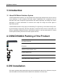
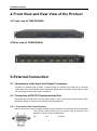
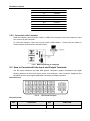
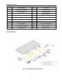
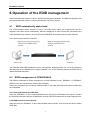
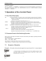
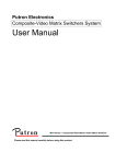
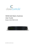
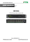
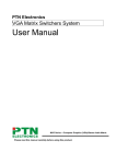
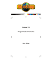
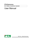
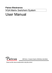
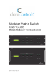
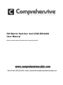
DVI Matrix Switcher 4x4 CSW-DVI440A
User Manual
Please read this manual carefully before using this product.
DVI Matrix Switcher
SAFETY PRECAUTIONS
Please read all instructions before attempting to unpack, install or operate this equipment
and before connecting the power supply.
Please keep the following in mind as you unpack and install this equipment:
• Always follow basic safety precaution to reduce the risk of fire, electrical shock and injury
to persons.
• To prevent fire or shock hazard, do not expose the unit to rain, moisture or install this
product near water.
• Never spill liquid of any kind on or into this product.
• Never push an object of any kind into this product through any openings or empty slots in
the unit, as you may damage parts inside the unit.
• Do not attach the power supply cabling to building surfaces.
• Use only the supplied power supply unit (PSU). Do not use the PSU if it is damaged.
• Do not allow anything to rest on the power cabling or allow any weight to be placed upon
it or any person walk on it.
• To protect the unit from overheating, do not block any vents or openings in the unit
housing that provide ventilation and allow for sufficient space for air circulate around the
unit.
ii
DVI Matrix Switcher
Contents
1. Introduction ................................................................................................................ 1
1.1
About DVI Matrix Switcher System .............................................................................. 1
2. CSW-DVI440A Packing of the Product ..................................................................... 1
3. CSW-DVI440A Installation ......................................................................................... 1
4. Front View and Rear View of the Product ................................................................ 2
4.1
Front view of CSW-DVI440A ......................................................................................... 2
4.2
Rear view of CSW-DVI440A .......................................................................................... 2
5. External Connection .................................................................................................. 2
5.1
Introduction of the Input and Output Connectors ....................................................... 2
5.2
Connection of RS-232 Communication Port................................................................ 2
5.2.1
Connection with Control System ............................................................................................... 2
5.2.2
Connection with Computer ........................................................................................................ 3
5.3
How to Connect with the Input and Output Terminals ................................................ 3
6. Operation of the EDID management ........................................................................ 5
6.1
EDID automatically shake hand................................................................................... 5
6.2
EDID management of CSW-DVI440A ............................................................................ 5
7. Operation of the Control Panel ................................................................................. 6
7.1 Front Panel Description .................................................................................................... 6
7.2 Command Format of the Switching Operation ................................................................ 6
7.3
Examples of Operation ................................................................................................. 6
8. Usage of the Remote Controller ................................................................................. 7
9. Communication Protocol and Command Codes .................................................... 8
10.
Specification ......................................................................................................... 11
11.
Troubleshooting & Maintenance ......................................................................... 12
iii
DVI Matrix Switcher
1. Introduction
1.1 About DVI Matrix Switcher System
CSW-DVI440A Matrix switcher is a high-performance digital signal switcher that can be used for
cross switching of multi computer and audio signal. Independent DVI component and I/O
terminals make each component signal transmit and switch separately; this design can reduce
attenuation of signal transmission to minimum and output the image and audio signal in
high-fidelity quality.
CSW-DVI440A switcher mostly apply in broadcasting TV engineering, multi-media meeting room,
big screen display engineering, television education, command control center or other fields. A/V
timing or separating switching function. With RS232 interface, it can be worked with PC, remote
control system and any other far-end control system devices.
2. CSW-DVI440A Packing of the Product
DVI Matrix Switcher
IR remote
RS-232 Communication Cord
Power Supply Cord
CD
User Manual and Quality Guarantee
3. DVI Installation
DVI matrix switchers adopt metal shell and can be stacked with other device. Moreover, they are
rack-mountable enclosure and can be installed in the standard 19 inches case.
1
DVI Matrix Switcher
4. Front View and Rear View of the Product
4.1 Front view of CSW-DVI440A
4.2 Rear view of CSW-DVI440A
5. External Connection
5.1 Introduction of the Input and Output Connectors
According to different type of matrix, computer signal I/O interface are made up of 4-channel
HDMI ports and DVI-D female ports respectively (digital audio included). Please refer to shell
silk-screen figure about other types of interface.
5.2 Connection of RS-232 Communication Port
Except the front control panel, the DVI matrix switcher can be control by far-end control system
through the Ethernet control via the RS-232 communication port.
5.2.1 Connection with Control System
With the RS-232 port, the DVI matrix switchers can be control by several kinds of control systems.
This RS-232 communication port is a female 9-pin D connector. The
definition of its pins is as the table below.
No.
Pin
Function
2
DVI Matrix Switcher
1
2
3
4
5
6
7
8
9
N/u
Tx
Rx
N/u
Gnd
N/u
N/u
N/u
N/u
F 5-1 9HDF
Unused
Transmit
Receive
Unused
Ground
Unused
Unused
Unused
Unused
5.2.2 Connection with Computer
When the switcher connects to the COM1 or COM2 of the computer with control software, users
can control it by that computer.
To control the switcher, users may use the public COM software. Please refer the details in
Communication Protocol and Command Codes
F 5-2 MHD connecting to computer
5.3 How to Connect with the Input and Output Terminals
The DVI matrix switchers may take DVD players, computers, graphic workstations and digital
showing platform as their input signal source, and projectors, video recorders, displayers and
amplifiers as their output signal destinations according to different situation.
DVI-I Dual Link:
F5—3
DVI-I Dual Link port
DVI pin function
PIN
FUNCTION
PIN
FUNCTION
1
T.M.D.S.Data2-
13
T.M.D.S.Data3+
3
DVI Matrix Switcher
2
T.M.D.S.Data2+
14
+5V Power
3
T.M.D.S. Data 2/4 Shield
15
Ground (for +5V)
4
T.M.D.S. Data 4-
16
Hot Plug Detect
5
T.M.D.S. Data 4+
17
T.M.D.S. Data 0-
6
DDC Clock
18
T.M.D.S. Data 0+
7
DDC Data
19
T.M.D.S. Data 0/5 Shield
8
No Connect
20
T.M.D.S.Data5-
9
T.M.D.S.Data1-
21
T.M.D.S.Data5+
10
T.M.D.S.Data1+
22
T.M.D.S. Clock Shield
11
T.M.D.S.Data1/3 Shield
23
T.M.D. S. Clock +
12
T.M.D.S.Data3-
24
T.M.D.S .Clock-
System Diagram:
4
DVI Matrix Switcher
6. Operation of the EDID management
CSW-DVI440A matrix switcher is built in the EDID management database. The EDID management can
be automatically shake hand, or manual exchanged, and factory restore.
6.1
EDID automatically shake hand
The CSW-DVI440A matrix switcher is built in the EDID data, which can communicate with the
displayers and video source automatically. When the displayers or video sources are connected to the
CSW-DVI440A matrix switcher, they will share the EDID/DDC information with the matrix switcher.
The communication solution is like this:
The CSW-DVI440A EDID database includes most popular displaying data, but not all the displaying
data because of the capability and firmware limitation. So, we can manually refresh the EDID data to
update the EDID data base.
6.2
EDID management of CSW-DVI440A
The RS232 commands for EDID management of CSW-DVI440A include: ”EDIDMon.” & ”EDIDMoff.”
(Please notice the text-transform, and the dot in behind.)
These two commands only accept by CSW-DVI440A, in the other CSW-DVI440A matrix models they
are unavailable.
6.2.1 Erase and Refresh the EDID data
When the “EDIDMOn.” is sent, CSW-DVI440A will auto copy the mix EDID data of all outputs. It means
the CSW-DVI440A will erase the old EDID data, and copy the EDID data which all output displays have.
6.2.2 EDID restore to factory default
When we send the “EDIDMoff.” to the CSW-DVI440A matrix switcher, it will recover the factory default
EDID data.
5
DVI Matrix Switcher
6.2.3 RS232 feedback:
When the “EDIDMOn.” or “EDIDMoff.” is correctly sent, all the connected displayers will be blank for
2~3 seconds and recover again. And, CSW-DVI440A will send out a RS232 feedback command
“EDIDMOn.” or “EDIDMoff.”.
7. Operation of the Control Panel
7.1 Front Panel Description
“AV”
AV synchronal button: To transfer video and audio signal synchronously by the switcher
Example: To transfer both the video and the audio signals from input channel No.3 to
output channel No.4.
Operation: Press buttons in this order “AV”,“3”,, “4””.
Video button: To transfer only video signals from input channel to output channel
Example: To transfer video signals from input channel No.3 to output channel No.4.
Operation: Press buttons in this order “VIDEO”, “3”, “4”.
Audio button: To transfer only audio signals from input channel to output channel
Example: To transfer audio signals from input channel No.2 to output channel No.3.
Operation: Press buttons in this order ““AUDIO”, “2”, “3””.
I/O Keypads: Keys to select I/O channels.
Example: To transfer input channel No.3 to output channel No.1
Operation: Press buttons in this order: “3” in INPUT area, “1” in OUTPUT area.
“VIDEO”
“AUDIO”
“1,2,3,4”
7.2 Command Format of the Switching Operation
With the front control panel, the switcher could be control directly and rapidly by pressing the buttons
under below format.
“Menu” +“Input Channel” +“Output Channel 1”
“Menu”: “AV”, “Audio”, “Video”
“Input Channel”: Fill with the number of input channel to be controlled
“Output Channel”: Fill with the number of output channels to be controlled
7.3
Examples of Operation
Example 1:To transfer video and audio signals from input channel No.1 to output channel
No.3,4
AV
Video
Audio
1, Press the button for switching mode “AV” for the switching mode of video
and audio (“Audio” for the switching mode of audio only; “Video” for the
switching mode of video only)
1
2
3
4
6
DVI Matrix Switcher
2, Press the button for input channel number“1”
2
2
3
3
4
4
3, Press the button for the first output channel number “3”
”
4, Press the button for the second output channel number “4”
Then, switching OK! audio/video switching from “1” to “3” and “4”
8. Usage of the Remote Controller
With the infrared remote controller, the matrix switcher could be control remotely. Because the function
buttons on the remote controller are the same with the ones on the front control panel, the remote
controller shares the same control operation and command format with the control panel.
The inputs
channels, from
0~9, and
plusing “10+”
for more
Menu, for
switching
source and
function
The outputs
channels, from
0~9, and
plusing “10+”
for more
7
DVI Matrix Switcher
9. Communication Protocol and Command
Codes
With this command system, the RS232 software is able to control and operate the CSW-DVI440A
Matrix with remotely.
Communication protocol:
Baud rate: 9600
Data bit: 8
Command
Types
Stop bit: 1
Command
Codes
Parity bit: none
Functions
System
Command
Operation Command
(PTN2.0 Command System)
/*Type;
Inquire the models information.
/%Lock;
Lock the keyboard of the control panel on the Matrix.
/%Unlock;
Unlock the keyboard of the control panel on the Matrix.
/^Version;
Inquire the version of firmware
/:MessageOff;
Turn off the feedback command from the com port. It will only show
the “switcher OK”.
/:MessageOn;
Turn on the feedback command from the com port.
EDIDMOn.
Enable auto EDID management.
EDIDMOff.
Disable auto EDID management.
Undo.
To cancel the previous operation.
Demo.
Switch to the “demo” mode, 1->1, 2->2, 3->3 … and so on.
[x1]All.
Transfer signals from the input channel [x1] to all output channels
All#.
Transfer all input signals to the corresponding output channels
respectively.
All$.
Switch off all the output channels.
[x1]#.
Transfer signals from the input channel [x1] to the output channel
[x1].
[x1]$.
Switch off the output channel [x1].
[x1] V[x2].
Transfer the video signals from the input channel [x1] to the output
channel [x2].
[x1]
V[x2],[x3],[x4].
Transfer the video signals from the input channel [x1] to the output
channels [x2], [x3] and [x4].
[x1] A[x2].
Transfer the audio signals from the input channel [x1] to the output
channel [x2].
[x1]
A[x2],[x3],[x4].
Transfer the audio signals from the input channel [x1] to the output
channels [x2], [x3] and [x4].
[x1] B[x2].
Transfer both the video and the audio signals from the input channel
[x1] to the output channel [x2].
8
DVI Matrix Switcher
[x1]
B[x2],[x3],[x4].
Transfer both the video and the audio signals from the input channel
[x1] to the output channels [x2], [x3] and [x4].
[x1]P[g].
Transfer both the video and the audio signals from the input channel
[x1] to the output group [g].
[g]PP[x2],[x3],[x
4].
Together the output channels [x2], [x3] and [x4] to the output group
[g].
S[g].
Inquire the output channels of output group [g].
Status[x1].
Inquire the input channel to the output channel [x1].
Status.
Inquire the input channel to the output channels one by one.
Save[Y].
Save the present operation to the preset command [Y]. [Y] ranges
from 0 to 9.
Recall[Y].
Recall the preset command [Y].
Clear[Y].
Clear the preset command [Y].
Note:
1. [x1], [x2], [x3] and [x4] are the symbols of input or output channels ranged according to the
model of the matrix switcher. If the symbols exceed the effective range, it would be taken as a
wrong command.
2. In above commands, “[”and “]” are symbols for easy reading and do not need to be typed in
actual operation.
3. Please remember to end the commands with the ending symbols “.” and “;”.
Detail Examples:
1、 Transfer signals from an input channel to all output channels: [x1]All.
Example: To transfer signals from the input channel No.3 to all output channels. Run Command:
“3All.”
2、 Transfer all input signals to the corresponding output channels respectively: All#.
Example: If this command is carried out on an MVG1616-A matrix switcher, the status of it will be:
1->1, 2->2, 3->3, 4->4……16->16.
3、 Switch off all the output channels: All$.
Example: After running this command, there will be no signals on all the output channels.
4、 Check the version of the firmware: /^Version;
To check the version of the firmware.
5、 Switch off the detail feedback command from the COM port: /:MessageOff;
Switch off the detail feedback information from the COM port. But, it will leave the “switch OK” as
the feedback, when you switch the matrix.
6、 Switch on the detail feedback command from the COM port: /:MessageOn;
Switch on the detail feedback information from the COM port. it will show the detail switch
information when it switch. Example: when switch 1->2 for Audio, it will feedback “A0102”.
7、 Transfer signals from an input channel to the corresponding output channel: [x]#.
Example: To transfer signals from the input channel No.5 to the output channel No.5.
Command: “5#.”
Run
8、Switch off an output channel: [x]$. Example: To switch off the output channel No.5. Run
9
DVI Matrix Switcher
Command: “5$.”
9、Switch both video and audio signals synchronously: [x1] B[x2].
Example: To transfer both the video and the audio signals from the input channel No.120 to the
output channel No.12,13,15. Run Command: “120B12,13,15.”
10、Transfer both the video and audio signals from input channel [x1] to output group [g]:
[x1]P[g].
Example: If together the output channel NO.1,3,5,7 to output group NO.2 by sent the command
“2PP1,3,5,7.”, then when send the command “1P2.”, the matrix will transfer both the video and
the audio signals from the input channel No.1 to output channel NO.1,3,5,7.
When you want to make a group [g], you should clear this group first. The command for clear
group is “[g]P0.”.
11、Inquire the input channel to the output channel [x]: Status[x].
Example: To inquire the input channel to the output channel No.23. Run Command: “Status23.”
12、Inquire the input channel to the output channels one by one: Status.
Example: To inquire the input channel to the output channels one by one.
“Status.”
Run Command:
13、Save the present operation to the preset command [Y]: Save[Y].
Example: To save the present operation to the preset command No.7. Run Command: “Save7.”
14、Recall the preset command [Y]: Recall[Y].
Example: To recall the preset command No.5. Run Command: “Recall5.”
15、Clear the preset command [Y]: Clear[Y].
Example: To clear the preset command No.5. Run Command: “Clear5.”
10
DVI Matrix Switcher
10. Specification
Video Input
Video Output
Input
DVI
Output
DVI
Input Connector
Female DB24+5
Output Connector
Female DB24+5
Input Level
T.M.D.S. 2.9V/3.3V
Output Level
T.M.D.S. 2.9V/3.3V
Input Impedance
75Ω
Output Impedance
75Ω
0 dB
Bandwidth
340 MHz (10.2 Gbit/s)
Max Time-delay
5nS (±1nS)
Switching Speed
200ns (Max.)
Video General
Gain
DVI 1.0 standard DVI-D full
Video Signal
digital
T.M.D.S signal
Crosstalk
<-50dB@5MHz
Supports Extended Display Identification Data (EDID) and Display Data Channel (DDC) data
EDID and DDC
using DVI and HDMI standards, EDID and DDC signals are actively buffered. The built-in
Management
EDID/DDC database can analyze these two signals, mix them, and realize the handshake of
them internally.
Compliant with High-bandwidth Digital Content Protection (HDCP) using DVI and HDMI 1.3
HDCP Management
standards. The built-in HDCP management technology can analyze HDCP key, and realize
the handshake internally.
Audio General
Frequency Response
Stereo Channel
Separation
20Hz ~ 20KHz
CMRR
>90dB@20Hz~20KHz
>80dB@1KHz
THD + Noise
1%@1KHz, 0.3%@20KHz at
nominal level
Pin Configurations
2 = TX, 3 = RX, 5 = GND
Buttons
Control Parts
Serial Control Port
RS-232, 9-pin female D
connector
IR Remote
Default IR remote
Front Panel Control
Options
TCP/IP control by PTNET(PTN's
programmable interface)
Power Supply
100VAC ~ 240VAC, 50/60Hz
Power Consumption
25W
Temperature
-20 ~ +70℃
Humidity
10% ~ 90%
Product Weight
1.5Kg
General
Case Dimension
W483 x H44 x D235mm
(1U high, full rack wide)
11
DVI Matrix Switcher
11. Troubleshooting & Maintenance
1)
When the output image in the destination device connected to the DVI Matrix (CSW-DVI440A) has
ghost, such as the projector output with ghost, please check the projector’s setting or try another
high quality connection cord.
2)
When there is a color losing or no video signal output,,Maybe the DVI cables haven’t been
connected as DVI criterion
3)
When the remote controller doesn’t works:
A. Maybe the battery is run out of, please change a new one.
B. Maybe the controller is broken, please ask the dealer to fix it.
4)
When user can not control the DVI Matrix (CSW-DVI440A) by computer through its COM port,
please check the COM port number in the software and make sure the COM port is in good
condition.
5)
If there is not “beep” sound when switching the I/O signal, please make sure the beeper is
switched-on. If so, the beeper inside the matrix may be broken. Please send it to the dealer for
fixing.
6)
When switching , the beeper beeps but without any output image:
A. Check with oscilloscope or multimeter if there is any signal at the input end. If there is no signal
input, it may be the input connection cord broken or the connectors loosen.
B. Check with oscilloscope or multimeter if there is any signal at the output end. If there is no
signal output, it may be the output connection cord broken or the connectors loosen.
C. Please make sure the destination device is exactly on the controlled output channel
D. If it is still the same after the above checking, it may be something wrong in the switcher.
Please send it to the dealer for fixing.
7)
If the output image is interfered, please make sure the system is earthed well.
8)
If the static becomes stronger when connecting the DVI connectors, it may be due to the incorrect
earthling of the power supply, Please earth it again correctly, and otherwise it would bring damage
to the switcher or shorten its natural life.
9)
If the Matrix cannot be controlled by the keys on the front panel, RS232 port or remote controller,
the host may has already been broken. Please send it to the dealer for fixing.
12
DVI Matrix Switcher
13