1
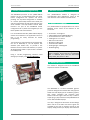
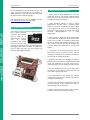
microOLED GOLDELOX DISPLAY
4D SYSTEMS
µOLED-128-G2
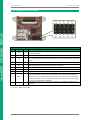
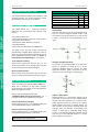
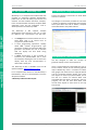
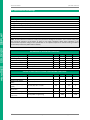
3. Pin Configuration and Summary
(2)
(4) (6)
(8) (10)
5V OUT IO2 IO1 GND 3.3V
+5V
(1)
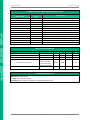
Pin
Symbol
I/O
1
+5V
P
2
5V OUT
P
3
TX
O
4
IO2
I/O
5
RX
I
6
7
8
IO1
GND
GND
I/O
P
P
9
RESET
I
10
3.3V
P
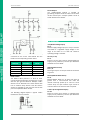
TX
(3)
RX
(5)
GND
(7)
RES
(9)
Interface/Programming Header
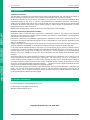
Description
Main Voltage Supply +ve input pin. Reverse polarity protected. Range is 4.0V to
5.5V, nominal 5.0V.
5V OUT provides approximately 4.7 V through a protection diode.
Asynchronous Serial Transmit pin. Output data is at TTL voltage levels. Connect
this pin to external device Serial Receive (Rx) signal. This pin is tolerant up to 5.0V
levels.
General purpose IO2 pin. See section 2.2 for more detail.
Asynchronous Serial Receive pin. Connect this pin to external device Serial
Transmit (Tx) signal. This pin is tolerant up to 5.0V levels.
General purpose IO1 pin. See section 2.2 for more detail.
Supply Ground.
Supply Ground.
Master Reset signal. Internally pulled up to 3.3V via a 4.7K resistor. An active Low
pulse greater than 2.0μs will reset the module. If the module needs to be reset
externally, only use open collector type circuits. This pin is not driven low by any
internal conditions. The host should control this pin via one of its port pins using
an open collector/drain arrangement.
Regulated 3.3 Volts output, maximum available current 50mA to power external
circuitry.
I = Input, O = Output, P = Power
© 2012 4D SYSTEMS
Page 5 of 17
www.4dsystems.com.au