1
microOLED GOLDELOX DISPLAY
4D SYSTEMS
µOLED-128-G2
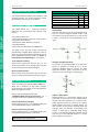
Sound Output:
The μOLED-128-G2 module is capable of
generating complex sounds and RTTTL tunes from
its IO1 and IO2 pins. A simple speaker circuit as
shown below can be utilised.
4.3. System Pins
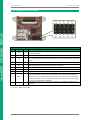
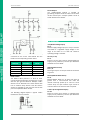
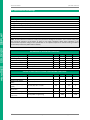
Unused buttons do not need resistors to be
connected to the circuit. Table below lists the
buttons and corresponding resistor values.
Number of
Buttons
1
2
3
4
5
Button
Number
SW1
SW2
SW3
SW4
SW5
Resistor
Value
22K
10K
4.7K
2.2K
1.2K
5V Out (~4.7V)
Pin 2:
External circuitry that requires approximately 5V
supply can be powered up via this pin. Maximum
available current is 50mA.
GND (Module Ground)
Pins 7, 8:
Device ground pins. These pins must be connected
to ground.
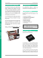
Dallas 1-Wire:
The Dallas 1-Wire protocol is a form of serial
communications designed to operate over a single
data line plus ground reference. Multiple 1 Wire
devices can be attached to the same shared data
line to network many devices. One wire device
support is available on both the IO1 and the IO2
pins on the μOLED-128-G2 module.
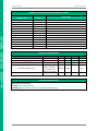
The following diagram depicts a typical 1-Wire
temperature sensor interface.
© 2012 4D SYSTEMS
+5V (Module Voltage Input)
Pin 1:
Module supply voltage input pin. This pin must be
connected to a regulated supply voltage in the
range of 4.0 Volts to 5.5 Volts DC. Nominal
operating voltage is 5.0 Volts.
RESET (Module Master Reset)
Pin 9:
Module Master Reset pin. An active low pulse of
greater than 2 micro-seconds will reset the
module. Internally pulled up to 3.3V via a 4.7K
resistor. Only use open collector type circuits to
reset the device if an external reset is required.
3.3Vout (3.3V Regulated Output)
Pin 10:
External circuitry that requires a regulated 3.3V
supply can be powered up via this pin. Maximum
available current is 50mA.
Page 7 of 17
www.4dsystems.com.au