1
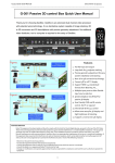
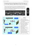
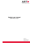
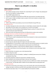
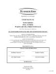
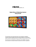
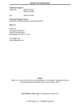
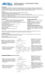
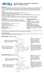
G-201 Quick User Manual
Document: G-201101
------------------------------------------------------------------------------------------------------------------------------------------------
G-201 Passive 3D Processor Quick User Manual
G-201 is an advanced dual channel passive 3D processor with 10 bits high end scaler
and Perfect Sync 3D RH/LH synchronization algorithm. It is a professional grade passive
3D demultiplexer and pure hardware video wall controller without geometry adjustment
function. User needs to use keystone or lens shift function to align the images from two
projectors. No additional video distributor, tool or computer is required for the setup.
Brief specifications
1.
2.
3.
4.
5.
Input: 1x DVI-I ( support VGA/DVI/HDM), up to 3840x1080
Output: 2x DVI-D (support DVI/HDMI), up to 2048x1080
Audio: In: HDMI, PC Jack, Out: HDMI, Analog PC Jack
Size: 303x157x36mm
Control: full function keypads, IR remote controller, RS232
Main Features
1. 3840x1080 input and 2048*1080
output
2. Support HDMI 1.4 standard 3D
formats from Blue Ray, game, PC…
3. DVI-I input port for the connection
with DVI, VGA & HDMI signals
4. Dual DVI-D output ports to support
DVI & HDMI connections
5. Embedded audio input and output
through HDMI connection
6. 10 bits scaler with high performance
de-interlace and scaling
7. 3D demultiplexer into RH/LH for
passive 3D display
8. Special algorithm for perfect RH/LH
synchronization in 3D mode
9. User friendly OSD and IR remote
control. No PC is required
10. Video wall controller function.
11.Support Sony TD-20/30V camcorder
1080i 60Hz frame packing 3D format
12. Convert 1080p 120Hz signal into
1080p 60Hz or 720p/XGA 120Hz for
passive and active 3D display.
Limited Warranty
This device is designed and tested to the highest standards and backed by a one year parts and labor warranty. Warranties are effective upon the
first delivery date to the end customer and are non-transferable. Warranty related repairs include parts and labor, but do not include repair of
faults resulting from user negligence, special modifications, abuse (mechanical damage), shipping damage, and/or other unusual damages. The
customer shall pay shipping charges when the unit is returned for repair. Manufacturer will pay shipping charges for return shipments to
customers.
Manufacturer does not assume responsibility for consequential damages, expenses or loss of revenue, inconvenience or interruption in operation
experienced by the customer. Warranty service shall not automatically extend the warranty period.
FCC/CE statement
This equipment has been tested and found to comply with the limits for a Class B digital device, pursuant to part 15 of the FCC Rules. These limits
are designed to provide reasonable protection against harmful interference when the equipment is operated in a residential / commercial
environment. This equipment generates, uses, and can radiate radio frequency energy and, if not installed and used in accordance with the
instruction manual, may cause harmful interference to radio communications. Operation of this equipment in a residential area is likely to cause
harmful interference in which case the user will be required to correct the interference at his own expense.
1
G-201 Quick User Manual
Document: G-201101
------------------------------------------------------------------------------------------------------------------------------------------------
Outlook and Functions
IR Receiver
Power Switch Audio out
OSD Menu
PC Audio in
R/L Identify
CH A/B OSD swap
Hot Keys
IR Extender
DVI-D out
(RH CH)
DVI-I IN
DVI-D out
(LH CH)
DC in 12V/2A
RS-232
Help tips
1. Toggle on CH A/B keypad will circulate the OSD control between CH-A & CH-B.
2. Toggle on 2D/3D keypad will circulate between Side By Side 3D mode and 2D (or auto 3D) mode.
3. OSD Lock / Unlock: When continuously press [MENU] key in Front Panel or IR Remote Controller for 12
seconds, the OSD function will be locked to prevent from the changes of the settings by other people. To
press MENU key for 12 seconds again, it will unlock OSD and user can manipulate the OSD again.
4. Picture menu in the OSD can only be activated while the input signal is not in color [Preset Mode]. To select
[Image Properties]
[Custom]
[Save], then user can activate [Picture] menu again.
5. [Image Setup] menu will not be activated if the input source is not from VGA.
6. Procedures to do system Reset: OSD Menu [Options] [Reset] [Reset All]
7. To set [Menu Time Out] to “0”, the OSD will appear till the OSD Menu has been turned off.
8. To set [Logo Time Out] to “0”, the splash screen logo will not be showed while G-201 is powered on.
9. Shortcut Hot Keys on the front panel are only functional while the OSD menu is not activated. Once the OSD
menu is activated, these keys will be served as OSD functional keys.
10. The audio from PC audio input Jack on the front panel will be mixed with video and output to RH/LH DVI-D
output ports through HDMI connection.
11. The embedded audio from HDMI input signal can be decoded and output to PC audio output Jack on the
front panel.
12. 3840x1080 input resolution can only be input through DualLink DVI cable and connector.
Minimum Equipment required for polarized 3D display
1. 1x G-201
5. 3D glasses (Paired with polarizer)
2. 2x Projectors (Native resolution above XGA
6. 3x DVI-HDMI cables or HDMI cables with 3x
with DVI/HDMI input connector)
DVI to HDMI adapters
3. 2x polarizers (For RH & LH eyes)
7. Video source with 3D content
4. 1x 3D screen (Silver matte)
2
G-201 Quick User Manual
Document: G-201101
------------------------------------------------------------------------------------------------------------------------------------------------
Installation process for 3D display
1. DVI to HDMI adapters or DVI to HDMI cables are required if the connection with video source or projectors
is not through DVI port.
2. Connect GeoBox with signal source, RH output to RH eye projector and LH output to LH eye projector.
3. Reset GeoBox to factory default settings via OSD [Option] menu to ensure no unexpected settings.
4. Install polarizer into RH & LH projectors before two projector image alignment. Make sure RH/LH
polarizers are set in correct projector, direction and angle with distance of 5-15cm to the lens to avoid
thermal damage.
5. Blue Ray player should be set at AUTO 3D (or 1080p@24Hz) for 1080p frame packing 3D display.
6. Turn on all devices. Some projector will search input source several times due to input timing change and
HDCP validation. GeoBox will automatically connect to input source. Then the screen will show up with
double images. If no input source is detected, GeoBox will go into power saving mode. The screen will
show [Power Saving Mode] message.
7. Select correct input source and set output resolution to match projector native resolution.
8. Make sure two projectors are in good focus and have the same settings.
9. Align two projector images overlapped together through projector keystone correction or lens shift.
10. Activate GeoBox [3D Properties] OSD to get correct input format and 3D settings.
11. Press [L/R ID] key on remote controller or front panel to confirm the right setting in RH/LH channels.
12. Test the final result and 3D performance.
Procedures for 3D display setting in GeoBox
1. After image position alignment, to activate [3D
Properties] in OSD to select 3D formats.
2. Select [Automatic] if the 3D signal is standard 3D
formats from Blue Ray player.
3. Select [Side By Side] or [Top-Bottom] based on
user’s 3D input sources.
4. Default setting is [Automatic]
1. Activate [Identify] menu to show “R & L”
characters on the screen at the same
time to verify the final 3D settings.
2. RH eye should see only “R” and LH eye
should see only “L”.
If the projector can accept 1080P@24Hz timing, please enable [1080P 24Hz output] to get better video
image, otherwise G-201 will output 1080P 60Hz signal.
3
G-201 Quick User Manual
Document: G-201101
-----------------------------------------------------------------------------------------------------------------------------------------------1. If it is not the result, then to set [Output Format] in
OSD menu is required.
2. Please swap [Left Eye Frame] and [Right Eye
Frame] in both RH/LH output channels to see the
right “R” & “L” characters in both eyes.
3. Complete system check is required if the problem
still existing.
If viewer still can’t verify “R” & “L” characters in both eyes, please check below again:
1. Is the screen for 3D display?
2. Are the Glasses and polarizers the same types and paired for the RH & LH eyes?
3. The default output setting of CH-A is for RH eye and CH-B is for LH eye. Please check from [Output Format]
menu as above OSD and make sure [Right Eye Frame] is set in CH-A and [Left Eye Frame] is set in CH-B.
4. Is the Blue Ray player set to [Auto 3D] or [1080p frame packing] mode to deliver 3D signal out?
5. If Side by Side or Top-Bottom 3D formats are used, please check the aspect ratio in video source output to
make sure GeoBox will receive full screen image.
6. Is there any HDMI or signal source compatibility issue and only one projector shows image?
After above procedures, apply 3D signal source and wear 3D glasses, user will enjoy the most
comfortable and healthy 3D system. It is the best solution for children with minimum harm to the eyes
Projector installation and setting guide for 3D display
1. G-201 doesn’t have geometry adjustment function, user needs to use keystone correction or lens shift
function in the projector to align the images. If the projectors don’t have lens shift or the lens shift range is
not enough, then the two projectors should be installed at top-bottom position for easy alignment. A side by
side position will be not possible to align two projector images together unless the projectors have lens shift,
both horizontal and vertical key stone correction or 4 corner position adjustment functions. A mounting rack
with flexible projection angle adjustments is recommended to install two projectors at Top-Bottom position.
2. The images from two projectors should be overlapped together. Good alignment will get clear image while in
2D mode and will also reduce eye fatigue for long term watching while in 3D mode.
3. GeoBox with geometry adjustment is available in G-301 & G-501 models so that user can easily get precise
image alignment between two projectors even the projectors are installed side by side.
4. Please make sure ventilation hot air will not affect each other.
5. The output brightness of the projector will differ in different Display Modes. User needs to select one with
higher brightness and enriched color. “Presentation” mode will give higher brightness but the color will differ
from original. sRGB will yield better color but the output brightness is usually comparative low. Two
projectors should have the same color settings to get the best 3D performance.
6. During the installation, the distance between the polarizer and the projector should be over 5cm to avoid
thermal damage due to high temperature from the projector. Higher lumens projector will create more heat
4
G-201 Quick User Manual
Document: G-201101
-----------------------------------------------------------------------------------------------------------------------------------------------and the distance should be larger. The polarizer can only tolerate up to about 60~70℃.
7. Pay attention to the HDMI compatibility due to different cables, equipment and connection distance. If the
distance is too long, HDMI extender shall be considered. It may extend the distance up to 50m to 100m.
Screen selection guide for 3D display
1. Silver Matte screen is required for polarized 3D display. Spectrum filter 3D system can use conventional
screen. Some factors are important in polarized 3D display screen:
i. The ability to retain polarization: higher value will have less ghost cross talk.
ii. Gain value: high value will have better brightness but may have viewing angle and hot spot issues.
iii. Flatness of the screen: Viewer may see wave screen and dis-alignment in geometry, especially in short
throw ratio projectors. It may be OK for 3D display but it will yield blurred image in 2D display.
2. The prices in different 3D screens have big range. Paint for 3D screen is available in the market.
3. If 2D & 3D display is required. User can select a screen with 2D/3D ability in the market.
4. Cheap silver paint and cloth with silver paste coating can be used as a temporary means to verify the
function of the 3D system if no 3D screen is available.
Projector selection guide for 3D display
1. It is necessary to select projectors with lens shift or keystone correction function for the image alignment.
2. A normal projector can be chosen for 3D display (no need to have 3D ready). Usually, XGA resolution will
create acceptable 3D video quality. A projector with higher native resolution, output brightness and contrast
ratio, will yield better performance similar to Movie Theater.
3. The output light from a projector with 3x LCD micro display (such as Epson) or LCOS (JVC or Sony) may
preserve polarization and the polarizer and glasses need to be carefully selected. Linear polarized system
can be used in most of Epson 3x LCD projectors. Optical spectrum type filter and glasses can be an
alternative in this case. DLP type projector is easier in polarizer and glasses selection.
4. The projector with throw ratio under 0.8 is not recommended because it will be more sensitive to the flatness
of the screen and create difficulty in image alignment.
5. DLP projector for business purpose may use different color wheel for higher brightness but degrade the
color performance. Please select video projector with HDMI or DVI input for home theater application.
6. For use in public area, the projectors with higher brightness should be considered. Projector with more than
3,000 lumens will be acceptable in limited ambient light presence. More than 4,000 lumens will create better
3D effect. Projector with full HD resolution and above 1,800 lumens will be recommended for home theater.
5
G-201 Quick User Manual
Document: G-201101
------------------------------------------------------------------------------------------------------------------------------------------------
Other Important Tips for 3D display
1. The final brightness to the eyes will be reduced due to 3D polarizer and glasses. Passive 3D brightness to
the eyes will be about 2.5x if compared with the same projector used in active (shutter) 3D system.
2. Incorrect aspect ratio adjustment of signal source may cause abnormal 3D display when the 3D format is
Side by Side or Top-Bottom.
3. Pair the glasses and polarizer is required: If viewer wears 3D glasses and sees the light from lamp through
one polarizer via RH eye with different side, direction and angle, viewer will see below conditions:
i.
If RH eye can see through the polarizer at any side, direction and angle, then this polarizer is not for RH
eye. It should belong to LH eye projector.
ii.
If viewer can’t see through or only see minor light at some angle or direction, then it can be for RH eye
projector. The side faced to the eye should be pointed out to the screen and the polarizer should be
installed at the same angle as viewer sees minimum light through.
4. GeoBox doesn’t have VGA output. Using DVI to VGA conversion box to connect projector through VGA port
is possible. However, the video quality in VGA port is not as good as digital interface. It may also have some
issue in position shift due to projector Auto Adjustment function. User needs to check above issues before
installation. To turn off projector Auto Adjustment function is one possible solution to fix this issue.
5. If 3D setting in Blue Ray is not correct, GeoBox will not be detected and 3D signal can’t be delivered to
GeoBox. Please set Blue Ray at auto 3D or 1080p@24Hz frame packing.
6. Usually front projection 3D screens will be silver (aluminum) surfaced in polarized 3D system unless optical
spectrum filter system from Dolby, Omega Optical or Infitec has been used. Optical spectrum filter system
can use normal 2D screen and minimize the ghost effect (crosstalk) but the filter and glasses will be in
higher price.
7. There are many kinds of 3D polarization system with different polarizing angles or directions. User needs to
check whether the glasses can match exactly with polarizer being used for the projectors.
8. Please note that head tilting and different viewing angles will affect crosstalk in linear polarization system.
9. In Side by Side or Top-Bottom 3D input mode, user may not see full OSD display from the video sources
(such as media player). Please set correct video source before implement 3D mode.
10. Although GeoBox is the most advanced and comfortable 3D control system, 3D screen, polarizer and
glasses are also important factors for a perfect 3D system.
Video Wall
G-201 has pure hardware video wall function. Each G-201 can handle two image channels with overlap at any
individual edge or all edges. It can do image cropping, split and assign the location of each image. The overlap
pixel between two images can also be adjusted pixel by pixel so that the video wall can meet the requirements in
different application environment. The maximum video wall can be up to 15x15 matrix display. If it works with
G-202 edge blending processor, it will provide a complete projector edge blending solution.
The purpose for Video Wall Setting is to determine the display Matrix, split the image, assign each
GeoBox/display device to the right location in the matrix and set overlap region.
6
G-201 Quick User Manual
Document: G-201101
------------------------------------------------------------------------------------------------------------------------------------------------
Press Menu Keypad on Front Panel or
remote controller to enter Video Wall OSD
menu
Use [Zoom] to split the display in horizontal
and vertical directions. GeoBox will cut the
image into different sections. Maximum
split image is 15 in both horizontal and
vertical directions.
For 1x3 displays
For 3x3 displays
Horizontal Zoom = 3
Horizontal Zoom =3
Vertical Zoom=1
Vertical Zoom = 3
Use [Pan] to determine the location of each
split image in the display in both horizontal
and vertical directions.
In the case of 3x3 matrix display as below ,
For No.
displays:
For No.
displays:
Horizontal Pan = 3
Horizontal Pan = 3
Vertical Pan = 1
Vertical Pan = 2
7
G-201 Quick User Manual
Document: G-201101
------------------------------------------------------------------------------------------------------------------------------------------------
Use [Overlap] to determine the overlapped
pixels between two adjunct displays. In
LCD video wall, it is related to the
dimension of the LCD bezel. In projector
edge blending, this overlap pixel shall be
determined based on the overlap region
between two projectors.
An Excel file can be provided for the calculation in different edge blending overlap value for projector
edge blending application.
Example for video wall with G-201 in 5x5
LCD displays. Each G-201 can control two
video wall displays.
Technical support
Please check more technical information in www.vnstw.com website:
Technical support:
Tel: +886-2-8751-2785 ext. 301
E-mail: [email protected]
Website: www.vnstw.com
8