1
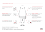
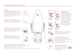
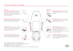
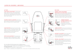
INSTALLATION MANUAL | CHAIR TO DECKRAIL
CONTENTS
ALUTECH DECKRAILS
2 SURFACE MOUNTED DECKRAIL
3 FLUSH MOUNTED DECKRAIL
4 DECKRAIL COMPONENTS
ALUTECH 200 SERIES
5 ATTACHING THE BRAKE CABLE
TO THE BRAKE MECHANISM
6 PROCEDURE
7 ATTACHING THE CHAIR TO THE DECKRAIL
8 ADJUSTING THE BRAKE CABLE
TO THE BRAKE HANDLE
ALUTECH 300/400/500 AND 600 SERIES
9 ATTACHING THE BRAKE CABLE
TO THE BRAKE MECHANISM
10 PROCEDURE
11 ROUTING THE DECKRAIL BRAKE CABLE
IN THE COLUMN
12 ATTACHING THE CHAIR TO THE DECKRAIL
13 ATTACHING THE BRAKE CABLE
TO THE BRAKE HANDLE
Store product inside in a protected environment. Handle with care.
Install as per instructions. Warranty invalid if not installed as per installation manual.
© Alu Design & Services AS | www.alu-design.no | T: +47 46 82 60 00 | [email protected]
Revision G | Specifications can be changed at any time | Please contact us for updated specifications before ordering
PAGE 1
ALUTECH SURFACE MOUNTED DECKRAILS | INSTALLATION MANUAL
PAGE 2
SURFACE MOUNTED DECKRAIL
NOTE: Alutech 200 and 300, 400, 500
and 600 series chairs are mounted on to
the surface mounted deckrails facing different
directions. Please pay special attention to the
indicator sticker.
The deckrail is fastened to the deck using
fasteners suitable to the deck material.
ALUTECH 200
SERIES
1.The deckrail needs a unobstructed flat surface
to be mounted on. There is an indicator sticker to show the front of the deckrail.
ALUTECH
300, 400, 500 and
600 SERIES
1
2.Fasten the deckrail to the deck surface using the
pre-drilled holes in the deckrail profile. Depending on the deck construction, more holes can be drilled in the deckrail profile.
3.For the Alutech 3200 / 3400 and 3300 / 3500 series:
Snap in the plastic profile to cover the
fastening screws.
2
NOTE: Fasteners from deckrail to deck not included.
NOTE: Ensure the deck rails are solidly fixed to the
deck construction.
© Alu Design & Services AS | www.alu-design.no | T: +47 46 82 60 00 | [email protected]
Revision G | Specifications can be changed at any time | Please contact us for updated specifications before ordering
3
ALUTECH FLUSH MOUNTED DECKRAILS | INSTALLATION MANUAL
PAGE 3
FLUSH MOUNTED DECKRAIL
NOTE: All Alu Design flush mounted deckrails have
the same mounting procedure.
DETAIL
4100 DECKRAIL SERIES 2
The deckrail is fastened to the deck using fasteners
suitable to the deck material.
There is an indicator sticker to show the front of
the deckrail.
1.The deckrail is mounted into a recess in the deck.
DETAIL
1
3500 DECKRAIL SERIES 2
3
4
2.The deckrail must ONLY rest on the bottom
of the cut our as indicated by the red arrows.
The deckrail must not be supported by the flanges.
3.Fasten the deckrail to the deck surface using the
pre-drilled holes in the deckrail profile. If required,
more holes can be drilled in the deckrail profile.
4.Snap in the plastic profile to cover the fastening
screws (plastic profile only for Alutech 3300 /
3500 and 3300 / 3500 series).
NOTE: Fasteners from deckrail to deck not included.
NOTE: Ensure the deck rails are solidly fixed to the
deck construction.
© Alu Design & Services AS | www.alu-design.no | T: +47 46 82 60 00 | [email protected]
Revision G | Specifications can be changed at any time | Please contact us for updated specifications before ordering
ALUTECH DECKRAILS | INSTALLATION MANUAL
PAGE 4
DECKRAIL COMPONENTS
All deckrails have the same type of components.
1 Deckrail with wagon
2 Brake cable
Alutech 200 - The brake cable is already
installed on the chair
Alutech 500 - Brake cable supplied
The locking screws need a 10 mm spanner
to adjust the brake cable
3 Connecting bolts
Alutech 200 - M8 x 35 - Flat head (hex screw)
The bolts are to be tightened with a 5 mm
Umbraco Key
4 Connecting bolts
Alutech 300, 400, 500 and 600
- M10 x 50 - Socket head (hex screw)
The bolts are to be tightened with a 8 mm
Umbraco Key
5 Snap-in plastic cover profile
NOTE: Fasteners from deckrail to deck not included.
For Alutech 4000 / 4100 use M6 Flat head (hex screw)
ALUTECH 4000 SERIES
ALUTECH 4100 SERIES
ALUTECH 3400 SERIES
ALUTECH 3500 SERIES
2
1
3
NOTE: It is advised to have two people working
together when connecting the chair to the deckrail.
© Alu Design & Services AS | www.alu-design.no | T: +47 46 82 60 00 | [email protected]
Revision G | Specifications can be changed at any time | Please contact us for updated specifications before ordering
4
5
ALUTECH 200 SERIES MOUNTED ON ALUTECH DECKRAILS
PAGE 5
PROCEDURE
The chair is mounted onto the deckrail wagon.
The movement of the wagon is controlled by
a brake mechanism.
1.The brake mechanism is controlled by a lever
mounted under the right side of the seat frame.
2.The brake cable must be connected to the
brake mechanism on the deckrail wagon before
the chair is mounted onto the wagon.
3.After the chair is mounted to the wagon, remove the seat cushion. Remove the screw underneath the front of the seat cushion. Lift up the front
of the cushion then push and lift up the back of the cushion.
4.The brake cable can then be adjusted and tightened with a 10 mm spanner.
NOTE: For instructions on using the deckrail brake,
see “User Manual 200 Series”.
1
2
1
3
2
3
NOTE: DO NOT bend the brake cable.
© Alu Design & Services AS | www.alu-design.no | T: +47 46 82 60 00 | [email protected]
Revision G | Specifications can be changed at any time | Please contact us for updated specifications before ordering
4
ALUTECH 200 SERIES MOUNTED ON ALUTECH DECKRAILS
PAGE 6
ATTACHING THE BRAKE CABLE
TO THE BRAKE MECHANISM
1.Identify the brake cable. Find the end with the
barrel nipple.
2.Identify the brake mechanism on the deckrail wagon.
3.Engage the barrel nipple in the plastic brake component. The plastic component is mounted
on an arm, this arm should be raised to allow
the barrel nipple to be fitted under the plastic
component and pulled up into its hole.
Please ensure that the nipple is inserted correctly
- some force may be necessary in order to do this.
BARREL
NIPPLE
1
BRAKE
MECHANISM
2
3
TIGHTEN TO
ENSURE NUT IS
FIXED IN PLACE
4
4.Push the end of the brake cable outer sleeve
into the aluminium bracket. Tighten the nut under
the aluminium bracket to hold the cable in place.
LIFT
3
© Alu Design & Services AS | www.alu-design.no | T: +47 46 82 60 00 | [email protected]
Revision G | Specifications can be changed at any time | Please contact us for updated specifications before ordering
ALUTECH 200 SERIES MOUNTED ON ALUTECH DECKRAILS
PAGE 7
ATTACHING THE CHAIR TO THE DECKRAIL
1.Orientate the chair relative to the deckrail.
There is an indicator sticker to show the front
of the deckrail and the chair.
FRONT OF
DECKRAIL
2.Feed the deckrail brake cable through the column foot and attach cable (see Page 5). Lift the chair above the deckrail and lower slowly down on to the deckrail wagon. Make sure that the brake cable is not bent.
2
Locate and place the chair using the bolt holes
as guides. Pull gently up on the brake cable as the chair is lowered into place.
DO NOT slide the chair on the wagon as the brake cable can become damaged.
3.Fasten the chair on to the deckrail wagon with
the bolts provided.
1
DETAIL
© Alu Design & Services AS | www.alu-design.no | T: +47 46 82 60 00 | [email protected]
Revision G | Specifications can be changed at any time | Please contact us for updated specifications before ordering
3
ALUTECH 200 SERIES MOUNTED ON ALUTECH DECKRAILS
PAGE 8
ADJUSTING THE BRAKE CABLE
TO THE BRAKE HANDLE
1.Remove the seat cushion (see Page 6, Fig 3).
Tension the brake cable using the brake cable
adjuster until the deckrail brake mechanism
releases and the chair can be moved on the
deckrail. The nuts are to be tightened with a
10 mm spanner.
BRAKE CABLE
ADJUSTER
THICK WIRE
1
2. When the brake lever is moved downwards the
deckrail brake mechanism should engage and
lock the chair in position on the deckrail.
Replace the seat cushion.
2
© Alu Design & Services AS | www.alu-design.no | T: +47 46 82 60 00 | [email protected]
Revision G | Specifications can be changed at any time | Please contact us for updated specifications before ordering
2
ALUTECH 300 / 400 / 500 AND 600 SERIES MOUNTED ON ALUTECH DECKRAILS
PAGE 9
PROCEDURE
The chair is mounted onto the deckrail wagon.
The movement of the wagon is controlled by
a brake mechanism.
1.The brake mechanism is controlled by a handle mounted on the side of the seat frame.
2.Use an Umbraco key to remove the four M6
screws. Recline the backrest. Grip the seat cushion
at the front and back edge. Lift the front edge of
the seat cushion 30 mm. Push the seat cushion back
towards the rear of the chair. Lift the back edge of the
seat cushion. Remove the seat cushion.
1
2
3
4
3. Connect the brake cable to the deckrail brake.
4. Route the cable through the column.
5. Attach the chair to the deckrail.
6. Attach the brake cable to the brake handle.
NOTE: For instructions on using the deckrail brake,
see “User Manual 300, 400, 500 and 600 Series”.
NOTE: DO NOT bend the brake cable.
© Alu Design & Services AS | www.alu-design.no | T: +47 46 82 60 00 | [email protected]
Revision G | Specifications can be changed at any time | Please contact us for updated specifications before ordering
ALUTECH 300 / 400 / 500 AND 600 SERIES MOUNTED ON ALUTECH DECKRAILS
PAGE 10
ATTACHING THE BRAKE CABLE
TO THE BRAKE MECHANISM
1.Identify the brake cable. Find the end with
the barrel nipple.
2.Identify the brake mechanism on the deckrail wagon.
3.Engage the barrel nipple in the plastic brake component. The plastic component is mounted
on an arm, this arm should be raised to allow
the barrel nipple to be fitted under the plastic
component and pulled up into its hole.
BARREL
NIPPLE
1
BRAKE
MECHANISM
2
3
TIGHTEN TO
ENSURE NUT IS
FIXED IN PLACE
4
IMPORTANT: Please ensure that the nipple is
inserted correctly - some force may be necessary in
order to do this.
4.Push the end of the brake cable outer sleeve
into the aluminium bracket. Tighten the nut under
the aluminium bracket to hold the cable in place.
LIFT
3
© Alu Design & Services AS | www.alu-design.no | T: +47 46 82 60 00 | [email protected]
Revision G | Specifications can be changed at any time | Please contact us for updated specifications before ordering
ALUTECH 300 / 400 / 500 AND 600 SERIES MOUNTED ON ALUTECH DECKRAILS
PAGE 11
ROUTING THE DECKRAIL
BRAKE CABLE IN THE COLUMN
1.Remove the seat cushion (see Page 10, Fig 2). Ensure the chair is in its lowest position.
Place the chair near the deckrail. Orientate
the chair relative to the deckrail (see Page 12).
2.Gain access to the underside of the chair column.
Feed the deckrail brake cable into the plastic tube mounted in the column. The cable will appear at
the top of the column.
1
1
Allow the cable to lie freely on the chair.
Fix the chair to the deck rail by using
the delivered bolts.
DO NOT route the brake cable under
other cables!
DO NOT remove any of the cables already
connected. These are installed and tested from
the factory and already 100% functional.
CORRECT
2
INCORRECT
© Alu Design & Services AS | www.alu-design.no | T: +47 46 82 60 00 | [email protected]
Revision G | Specifications can be changed at any time | Please contact us for updated specifications before ordering
2
ALUTECH 300 / 400 / 500 AND 600 SERIES MOUNTED ON ALUTECH DECKRAILS
PAGE 12
ATTACHING THE CHAIR TO THE DECKRAIL
1.Orientate the chair relative to the deckrail as indicated below. There is an indicator sticker
to show the front of the deckrail and the chair.
FRONT OF
DECKRAIL
2.Ensure the chair is in its lowest position.
Lift the chair above the deckrail and lower slowly
down onto the deckrail wagon. Place the chair
directly in place using the bolt holes as guides.
Pull gently up on the brake cable as the chair
is lowered into place. Make sure that the brake
cable is not bent.
2
DO NOT slide the chair on the wagon as the brake cable can become damaged.
DO NOT make sharp bends of the brake cable
as it can become damaged.
3.Fasten the chair on to the deckrail wagon
with the bolts provided.
FRO
NT
1
DETAIL
© Alu Design & Services AS | www.alu-design.no | T: +47 46 82 60 00 | [email protected]
Revision G | Specifications can be changed at any time | Please contact us for updated specifications before ordering
3
ALUTECH 300 / 400 / 500 AND 600 SERIES MOUNTED ON ALUTECH DECKRAILS
PAGE 13
ATTACHING THE BRAKE CABLE TO THE BRAKE HANDLE
1.Route the brake cable to the brake mechanism.
2.Ensure the chair is in lowest position before connecting
the release cable to the mechanism.
3. Enter the thick wire end of the brake cable into the brake lever
and enter the outer cable adjuster into the brake cable bracket.
4. To ensure the correct tension in the cable, check to see if the
deckrail can be locked and unlocked by using the lever.
If the deckrail can be locked and unlocked, tighten the nuts
with a 10 mm spanner.
1
Before installing the seat cushion, lift the chair to its highest position
to assure that the release cable moves freely.
For details on adjusting and operating the deckrail brake,
see “User Manual 300 / 400 / 500 and 600 Series”.
NOTE: Assembly shown without chair in DETAIL image.
DETAIL
DO NOT enter complete wire end through the brake lever.
Attach the brake cable to the brake mechanism ONLY as shown
(see Fig 2).
Replace the seat cushion.
© Alu Design & Services AS | www.alu-design.no | T: +47 46 82 60 00 | [email protected]
Revision G | Specifications can be changed at any time | Please contact us for updated specifications before ordering
2