1
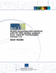
DRIVELAB KIT
USER MANUAL
www.opal-rt.com
Published by
Opal-RT Technologies, Inc. 1751 Richardson, suite 2525 Montréal (Québec) Canada H3K 1G6
www.opal-rt.com
© 03/2012 Opal-RT Technologies, Inc. All rights reserved
Printed in Canada


SYMBOL DEFINITIONS
The following table lists the symbols used in this document to denote certain conditions:
Symbol
Definition
ATTENTION: Identifies information that requires special consideration
TIP: Identifies advice or hints for the user, often in terms of performing a task
REFERENCE _ INTERNAL: Identifies an additional source of information within the bookset.
CAUTION
Indicates a situation which, if not avoided, may result in equipment or work (data) on the system being
damaged or lost, or may result in the inability to properly operate the process.
Indicates a situation where users must observe precautions for handling electrostatic sensitive devices.
!
!
iii
CAUTION: Indicates a potentially hazardous situation which, if not avoided, may result in minor or
moderate injury. It may also be used to alert against unsafe practices.
WARNING: Indicates a potentially hazardous situation which, if not avoided, could result in serious injury or
death.
Opal-RT Technologies DriveLab User Manual


CONTENTS
OVERVIEW............................................................................................................................................... 7
DRIVELAB KIT CONTENTS.................................................................................................................. 7
HOW THE KIT WORKS......................................................................................................................... 8
HOW THE DRIVELAB BOX WORKS..................................................................................................... 9
power electronics.............................................................................................................................................10
fault detection and fault clearance. ..................................................................................................................10
GETTING STARTED............................................................................................................................... 12
HOW TO CONNECT THE DRIVELAB BOX......................................................................................... 12
cabling. .............................................................................................................................................................13
powering up sequence........................................................................................................................................13
CONTROL HARDWARE......................................................................................................................... 14
REAL-TIME SIMULATOR I/O............................................................................................................... 14
analog inputs.....................................................................................................................................................14
digital inputs......................................................................................................................................................14
I/O Cables.........................................................................................................................................................15
113-0372 DIGITAL I/O CABLE....................................................................................................................................... 15
EXTERNAL POWER SUPPLY..........................................................................................................................15
MOTORS................................................................................................................................................. 16
DC MOTOR.......................................................................................................................................... 17
connections.......................................................................................................................................................17
model. ...............................................................................................................................................................17
DC GENERATOR................................................................................................................................. 18
connections.......................................................................................................................................................18
model. ...............................................................................................................................................................18
BLDC MOTOR..................................................................................................................................... 19
connections.......................................................................................................................................................19
model. ...............................................................................................................................................................19
AC INDUCTION MOTOR..................................................................................................................... 20
connections.......................................................................................................................................................20
model. ...............................................................................................................................................................20
CONTROL SOFTWARE......................................................................................................................... 21
HOW THE MODEL WORKS................................................................................................................ 21
THE MODEL.....................................................................................................................................................22
THE TESTDRIVE INTERFACE............................................................................................................ 24
testdrive workbench for drivelab......................................................................................................................24
Virtual Scope Panel........................................................................................................................................................ 26
5
Opal-RT Technologies DriveLab User Manual


SPECIFICATIONS................................................................................................................................... 27
DRIVELAB BOX . ................................................................................................................................ 27
DC MOTOR.......................................................................................................................................... 27
BLDC motor......................................................................................................................................................27
DC GENERATOR................................................................................................................................. 28
AC INDUCTION MOTOR..................................................................................................................... 28
PIN ASSIGNMENTS............................................................................................................................... 29
encoder pin assignments. ...................................................................................................................................29
BLDC Encoder............................................................................................................................................................... 29
AC Induction Encoder.................................................................................................................................................... 29
DC Generator Encoder.................................................................................................................................................. 29
DB37 AND 50-PIN CONNECTOR PIN ASSIGNMENTS..................................................................... 30
OP5142EX1 AnalogIn Simulink Block and OP5340...................................................................................................... 30
DB37 AND 40-PIN CONNECTOR PIN ASSIGNMENTS..................................................................... 31
OP5142EX1 Encoder In Simulink Block and OP5353................................................................................................... 31
OP5142EX1 Digital In Simulink Block and OP5353....................................................................................................... 32
OP5142EX1 EventGenerator Simulink Block and OP5353........................................................................................... 33
TROUBLESHOOTING............................................................................................................................ 37
APPENDIX A - SPEED, TORQUE CURVES........................................................................................... 39
Dc motor speed-torque, current-torque and power efficiency-speed curves. ....................................................39
Ac induction equivalent circuit model and torque-speed curve...........................................................................40
APPENDIX B........................................................................................................................................... 43
List and location of components on the drivelab board......................................................................................43
drivelab board chart. ........................................................................................................................................46
APPENDIX C........................................................................................................................................... 48
External power supply. .....................................................................................................................................48
LIMITED WARRANTY............................................................................................................................. 50
Limited Warranty...............................................................................................................................................50
Return Policy...................................................................................................................................................50
Exclusions. .......................................................................................................................................................50
Warranty Limitation and Exclusion....................................................................................................................51
Disclaimer of Unstated Warranties . .................................................................................................................51
Limitation of Liability .........................................................................................................................................51
DriveLab User Manual
Opal-RT Technologies
6
OVERVIEW
DriveLab kit contents
OVERVIEW
Opal-RT DriveLab kit is a fully integrated motor drive kit, designed to enable the user to perform a
variety of experiments on AC and DC machines. The system was specifically designed for teaching,
experimentation and research. The system consists of four major components: motors, power
electronics, control hardware and control software. The purpose of this document is to provide
information, instructions and details about those components.
DRIVELAB KIT CONTENTS
• 1 Real-time simulator (target computer)
• 1 TestDrive pack (model) with user interface
• 4 motors:
-- 1 PM-DC (DC motor, see ”DC Motor” on page 17)
-- 1 PM-DC Gen (DC generator with encoder, see “Dc Generator” on page 18)
-- 1 BLDC (BLDC motor with encoder, see “BLDC Motor” on page 19)
-- 1 Async (AC Induction motor with encoder, see “AC Induction Motor” on page 20)
• 1 DriveLab box
• 1 External DC power supply
• 2 I/O cables (one for digital control signals and one for analog input signals)
• 2 Encoder cables (5-pin and 8-pin)
• 8 Banana plug cables (3 for inverter #1, 3 for inverter #2 and 2 for external power supply)
• Other interface cables (power cord, ethernet cable, etc)
7
Opal-RT Technologies DriveLab User Manual
OVERVIEW
HOW the kit WORKS
HOW THE KIT WORKS
The DriveLab kit consists of two electric motors fixed on a base plate. Since the motors can be
physically coupled, this document assumes that one of the motors is used as a motor and that the other
is used as a generator (load of the motor).
Each motor is driven by a separate power converter connected to a common 36 VDC bus. This DC
bus is powered by an external power supply (provided with the kit). The power converters have all the
drivers and circuit accessories needed to be controlled by PWM logical signals. Current, voltage and
mechanical angle/speed sensors give the required feedback to the real-time control prototyping system.
36 VDC BUS
Power
Converter
Motor
Drivers &
Protection
Power
Converter
Motor
Drivers &
Protection
Sensors
RT-LAB
Real-Time Prototyping System
HOST PC
Figure 1: DriveLab solution block diagram
The image (Figure 2) shows the four major DriveLab kit components (motors, power electronics, control
hardware (real-time simulator) and control software in relation to the function diagram.
POWER
ENC_1
OPAL-RT
Technologies
MOTOR 1
FAULT
ENC_2
+5V
+12V
-12V
CLEAR
PHASES
MOTOR 2
A1
B1
Motor
Drivers &
Protection
B2
+
C2
INVERTER 2
DRIVELAB BOX
36 VDC BUS
Power
Converter
A2
INVERTER 1
MOTORS
MOTOR DC
PHASES
C1
CONTROL SIGNALS CONNECTOR
ANALOG INPUTS CONNECTOR
Motor
Sensors
Power
Converter
Drivers &
Protection
RT-LAB
Real-Time Prototyping System
HOST PC
HOST COMPUTER
SIMULATOR
Figure 2: DriveLab solution schematic with components
DriveLab User Manual
Opal-RT Technologies
8
OVERVIEW
HOW THE DRIVELAB BOX WORKS
HOW THE DRIVELAB BOX WORKS
The DriveLab box is a motor drive system in which the PWM pulses generated by the real-time
simulator dictate the modulation of a voltage-source converter, and then control the motor. It consists
of two identical, independent 3-phase PWM inverter circuits, each one with 3 MOSFETs that allow
driving two motors simultaneously. Both circuits provide current feedback for the first two phases (A &
B). A 36 VDC-bus voltage is provided to reduce electrical hazards. Feedback of this bus voltage level is
also provided. The DriveLab box passes the encoder feedback to the real-time simulator. The box also
provides fault detection and clearance.
A
B
C
POWER
ENC_1
FAULT
ENC_2
OPAL-RT
Technologies
MOTOR 1
+5V
+12V
-12V
CLEAR
PHASES
MOTOR 2
A1
B1
MOTOR DC
PHASES
A2
C1
B2
+
C2
-
CONTROL SIGNALS CONNECTOR
ANALOG INPUTS CONNECTOR
INVERTER 1
D
E
INVERTER 2
F
G
Figure 3: The DriveLab box interface
A. Encoder connectors.
Enc_1 is an 8-pin connector and Enc_2 is a 5-pin connector. See the “Motors” on page 16
section for details.
B. Fault
LEDs for each motor and a clear button (see “fault detection and fault clearance” on page 10).
Label
Display
Motor 1
A fault on motor #1 (via inverter circuit #1)
Motor 2
A fault on motor #2 (via inverter circuit #2)
C. Power
Indicator LEDs display power status for the various power supplies. If all LEDs are off, some
functions may not work.
Label
Display
+5V
The DriveLab box is properly powered with +5V
+12V
The DriveLab box is properly powered with +12V
-12V
The DriveLab box is properly powered with -12V
D. Analog inputs connector
Connects DriveLab box to simulator analog inputs.
E. Control signals connector
Connects DriveLab box to simulator digital signals (encoders, hall effects, clear fault, and gate
firing for all 3 phases for each inverter).
F. Phases
Voltage output from the three phases (A, B and C) of inverter 1 and 2
G. Power connector
36V external power supply connector to power the board’s DC bus.
9
Opal-RT Technologies DriveLab User Manual
OVERVIEW
HOW THE DRIVELAB BOX WORKS
power electronics
The DriveLab box circuit board manages inputs and outputs (see schematic in Figure 4) using
MOSFET switching devices, converters, inverters and sensors, among numerous other components.
These components are linked to interfaces provided on the DriveLab box (see Figure 3 for details).
Each interface provides a connection to another component, such as a host computer, simulator or
motors.
The PCB housed within the DriveLab box also offers additional connector components and switches
and should only be accessed by qualified technicians and, in certain cases, advanced users. Additional
details are provided in “Appendix B” on page 43.
fault detection and fault clearance
The DriveLab box is physically protected against overcurrents. When an overcurrent occurs, it
generates a fault, which is indicated in two ways:
1. The front LED lights indicate a fault status (Motor 1 or Motor 2, depending on which inverter is in
fault) status of the front associated to that inverter circuit. If the LED is on, it means a fault has
occurred on this inverter. The protection ensures the circuit is not damaged and will stop any
activity on that circuit.
2. The real-time model also offers the fault detection option using a digital input line. When a fault
occurs, the input status changes from 0 (normal operation) to 1 in the real-time model.
The DriveLab box lets users clear the fault using one of two options and continue with the activity:
1. Press the “Clear” button on the front of the DriveLab box to clear the fault.
Note: the Clear function is applied to both circuits, clearing the fault on circuit #1 and on circuit #2. If the fault
is properly cleared, the LED that indicated a fault should go off.
2. The real-time model also provides a fault clearance option, which will change the status of a
digital signal (from low to high). This signal, sent from the real-time simulator to the DriveLab box,
has the same effect as pushing the “Clear” button on the box. After clearing the fault, the fault
trigger should be returned to its initial position to ensure the “clear fault” signal does not stay on
indefinitely. The fault LED will turn off.
DriveLab User Manual
Opal-RT Technologies
10
OVERVIEW
HOW THE DRIVELAB BOX WORKS
Here is a simplified schematic to illustrate how the board (within the DriveLab box) channels signals:
A1
B1
A2
C1
B2
C2
+36V
GND
PWM Inverter 1
SD
A
B1 B2
B
C
C1 C2
FAULT
C
A1 A2
FLTCLR
B
C1 C2
FAULT
A
B1 B2
FLTCLR
A1 A2
SD
PWM Inverter 2
Figure 4: The DriveLab inverter circuits schematic
11
Opal-RT Technologies DriveLab User Manual
getting started
How To Connect the Drivelab Box
GETTING STARTED
HOW TO CONNECT THE DRIVELAB BOX
The DriveLab box has thirteen (13) connectors, one in the back and twelve in the front.
POWER
ENC_1
FAULT
ENC_2
OPAL-RT
Technologies
MOTOR 1
+5V
+12V
-12V
CLEAR
PHASES
MOTOR 2
A1
ANALOG INPUTS CONNECTOR
B1
MOTOR DC
PHASES
C1
A2
B2
+
C2
-
CONTROL SIGNALS CONNECTOR
INVERTER 1
INVERTER 2
FRONT
BACK
Figure 5: DriveLab box connectors
Location
Label
Type
Used for
Back
N/A
Power cord
Standard 120VAC power cord
Front
ENC_1
Encoder 8 pins
Encoder cable (8-pin type)
ENC_2
Encoder 5 pins
Encoder cable (5-pin type)
MOTOR DC +
Banana plug
External power supply +36V
MOTOR DC -
Banana plug
External power supply ground
Control signals
40-pin
Control signals (digital) and feedback from/to simulator
Analog Inputs
50-pin
Feedback returned to simulator through analog signals
Phase A1
Banana plug
Controlling phase A of motor on inverter circuit #1
Phase B1
Banana plug
Controlling phase B of motor on inverter circuit #1
Phase C1
Banana plug
Controlling phase C of motor on inverter circuit #1
Phase A2
Banana plug
Controlling phase A of motor on inverter circuit #2
Phase B2
Banana plug
Controlling phase B of motor on inverter circuit #2
Phase C2
Banana plug
Controlling phase C of motor on inverter circuit #2
Table 1: DriveLab box connectors
DriveLab User Manual
Opal-RT Technologies
12
getting started
How To Connect the Drivelab Box
cabling
Before turning the DriveLab box on, make sure all connections are secured (power cord, encoder
cables, external power supply cables, motor cables and I/O cables):
0-15
Simulator I/Os
OP5330 16 DA
OP5340 16 AD
B
16-31
0-15
A
16-31
0-15
B
16-31
0-15
A
16-31
0-15
B
16-31
0-15
A
A
B
16-31
0-15
B
16-31
0-15
A
PMDC MOTOR
OP5353 32 DI
OP5354 32 DO
16-31
8-pins
5-pins
POWER
ENC_1
ENC_2
OPAL-RT
Technologies
MOTOR 1
FAULT
A
B
Gr2
Gr1
PMDC GENERATOR
+5V
+12V
PHASES
MOTOR 2
B1
MOTOR DC
PHASES
C1
A2
B2
+
C2
-
CONTROL SIGNALS CONNECTOR
INVERTER 1
INVERTER 2
120
A1
ANALOG INPUTS CONNECTOR
113-0464
EXTERNAL
POWER SUPPLY
-12V
CLEAR
Power 36 V
120V/240V
Enc_1 = 8 pins for BLDC (use cable 113-0362)
Enc_2 = 5 pins for PM DC Gen or Async (use cable 113-0357)
113-0463
Figure 6: Complete cabling diagram
1. Make sure that the DriveLab box, real-time target and external power supply are off.
1. Connect the I/Os from the DriveLab box to the simulator using cables 113-0463 and 113-0464.
2. Connect the desired motor (PMDC in the illustration) to the DriveLab box banana jacks using the
cables provided, making sure to respect color coding. (shown in Figure 6
3. Connect the DriveLab encoder to the motor using either cable 113-0357 (5-pin connector) or 1130362 (8-pin connector).
4. Connect the external power supply (make sure that it is OFF and that the voltage control is set to
0) to the banana jacks on the front of the DriveLab box.
5. Connect the standard power cord to the DriveLab box and plug into an adequate wall plug.
powering up sequence
!
Before connecting any power supply to the DriveLab box, make certain that the external power supply
voltage setting is set to a maximum of 36 VDC (see “Appendix C” on page 48).
1. Put DriveLab power switch (at the back of the unit) in the ON position. The three (3) LEDs in the
front (+5V, +12V and -12V) will light.
2. Make sure that the external power supply voltage is set to 0. Turn on the power supply.
3. Turn on real-time target (simulator).
4. Slowly increase the voltage until you reach 36V.
Note: Upon powering up the DriveLab box, there may be some noise caused by the lower voltages. This
noise will disappear once the unit reaches its nominal voltage setting. This same noise may also occur due
to lowering voltages during the powering off sequence.
13
Opal-RT Technologies DriveLab User Manual
CONTROL HARDWARE
REAL-TIME SIMULATOR I/O
CONTROL HARDWARE
The control hardware is comprised of Opal-RT engineered components and some standard computer
components (such as Intel processors) to achieve very high-speed and precision real-time simulation.
The DriveLab kit includes the external power supply, the interface cables and the real-time simulator.
The real-time simulator components can be divided into two categories: PC-based and Inputs/Outputs
(I/Os). A motherboard, hard drive with RTOS, power supply and processors are the main components
of the PC-based category. An FPGA board based on Spartan-3 Xilinx’s chip with PCI Express interface,
digital I/O boards and +/-16V analog board are the main components of the I/O category. For the
DriveLab kit application, we will focus on the I/O interface.
REAL-TIME SIMULATOR I/O
analog inputs
Opal-RT’s standard analog input range is +/-20V. The DriveLab application scales the voltages in order
to comply with this specification. The analog input carrier connector on the real-time simulator is known
as a DB37F connector (see “I/O Cables” on page 15 for details).
In this configuration, analog inputs are used to read the phase currents and the DC bus voltage.
• Currents A1 and B1 of inverter circuit #1
• Currents A2 and B2 of inverter circuit #2
• +36V common DC bus voltage
Note that currents are measured and sent as voltages by the DriveLab box (see “Power electronics” section
for more details). A gain is applied during the conversion. See “Control software” section on how to retrieve
the exact current values in the model.
digital inputs
Opal-RT digital inputs are opto-isolated.
In this configuration, digital inputs are used to read encoder feedback provided by the DriveLab box and
the encoders:
•
•
•
•
Fault detection on inverter circuit #1
Fault detection on inverter circuit #2
Encoder feedback (A, B, Z) from both encoders
Hall effects (U1, V1, W1) of encoder 1 (8-pin)
Opal-RT digital outputs are opto-isolated and require an external DC voltage source as a voltage
reference level for the digital signals to be outputted. In the DriveLab application, this voltage is fed by
the DriveLab box to the real-time simulator.
In this configuration, digital outputs are used to provide signals to the DriveLab box:
• Firing of phase A1, B1 & C1 (PWMs) on inverter circuit #1
• Firing of phase A2, B2 & C2 (PWMs) on inverter circuit #2
• Fault clearance signal (common to both circuits)
DriveLab User Manual
Opal-RT Technologies
14
CONTROL HARDWARE
REAL-TIME SIMULATOR I/O
I/O Cables
Real-time simulator inputs and outputs must be properly connected to the DriveLab box to interact
with it. This is why Opal-RT provides two custom cables to connect both systems; each cable has two
different connectors at either end:
113-0371 ANALOG INPUT CABLE
• Standard DB37M connector (to connect to the simulator analog I/O slot).
• 50-pin connector (to connect to the DriveLab box “analog inputs” connector).
Refer to “pin assignments” on page 29 for the analog input DB37 pin description and for the 50-pin
“analog inputs” connector pin description.
113-0372 DIGITAL I/O CABLE
• Standard DB37M connector (to connect to the simulator digital I/O slot).
• 40-pin connector (to connect to the DriveLab box “control signals” connector).
Refer to “pin assignments” for the digital I/O DB37 pin description and for the 40-pin “control signals”
connector pin description.
CAUTION The “analog input” and the “control signal” connectors on the DriveLab box are different sizes, therefore,
there is no risk of plugging in the wrong connector.
However, the connectors on the simulator are the same size, therefore it is IMPERATIVE to plug the
“analog input” cable into the analog input slot and the “control signal” cable into the digital I/O slots.
Failure to do so may result in hardware damage of the DriveLab box, the cable and the real-time
simulator. If you are not sure, refer to the System Integration documentation found on the CD provided
with the system or refer to your project manager.
EXTERNAL POWER SUPPLY
The external power supply provided with the system is used to power the DriveLab box, which requires
an external +36VDC source to power the common DC bus. Although the power supply provided may be
able to reach higher voltages, it must be set to +36VDC. Higher voltages may result in damage to the
DriveLab box and to other hardware components.
Before connecting the external power supply to the DriveLab box, set the power supply to 0V. Then, connect
the external power supply to the DriveLab box and power them. It is important to power the DriveLab box
and the external power supply after both units are connected together.
15
Opal-RT Technologies DriveLab User Manual
Motors
REAL-TIME SIMULATOR I/O
MOTORS
The DriveLab kit includes four different motor types: DC, AC induction, BLDC and DC generator.
Motors can be coupled (as shown) or left separate. The image below shows a typical configuration.
Motors are connected to other devices using various types of cables: banana jack cables, custom 40
or 50 pin to DB37 or round 5 or 8 pin encoder cables.
Figure 7: The DriveLab motors
Note: Only the BLDC motor uses the 8-pin encoder (pins 6, 7, and 8). The DC generator and the AC Induction
motor both use the 5-pin encoder. Therefore, if the DC generator and the AC Induction motor are used in
the same experiment, it is possible to monitor only one encoder. The encoders’ resolution is 1000 pulses
per revolution.
DriveLab User Manual
Opal-RT Technologies
16
Motors
DC Motor
DC MOTOR
The DriveLab kit is equipped with a third party (COTS) DC motor that can be connected to the
DriveLab box. You must follow the connection instructions provided in Table 2 to connect this motor to
the DriveLab box inverter connectors.
connections
The DC motor has two (2) connectors: Phase 1 (red) on the DriveLab box must be connected to the
red connector on the DC motor. Phase 2 (yellow) on the DriveLab box must be connected to the black
connector on the DC motor.
DC Motor Connectors
DriveLab box connectors
Name
Location
Color
Type
Connector
Phase 1
Side
Red
Banana plug
A1 or A2
Color
Red
Type
Banana plug
Phase 2
Side
Black
Banana plug
B1 or B2
Yellow
Banana plug
Table 2: DC motor connectors
Here is an example of connections in which the DC motor is connected to inverter circuit 2.
MOTORS
DC Gen
113-0357
DC
Generator
Gr2
A
B
OP5353 32 DI
Gr1
A
B
OP5330 16 DA
OP5354 32 DO
OP5340 16 AD
8-pins
5-pins
POWER
ENC_1
ENC_2
OPAL-RT
Technologies
MOTOR 1
FAULT
OP5142 FPGA backplane
Simulator I/Os
+5V
+12V
-12V
CLEAR
PHASES
MOTOR 2
A1
ANALOG INPUTS CONNECTOR
B1
B2
+
C2
INVERTER 1
113-0464
A2
Power 36 V
120V/240V
MOTOR DC
PHASES
C1
CONTROL SIGNALS CONNECTOR
INVERTER 2
Enc_1 = 8 pins for BLDC (use cable 113-0362)
Enc_2 = 5 pins for DC Gen or Async (use cable 113-0357)
113-0463
Figure 8: DC motor setup example
model
Opal-RT provides a basic control and feedback open loop model for users who do not have their own
DC motor RT-LAB model. The DriveLab RT-LAB Simulink model contains control, I/O interface and
feedback subsystems to run the DC motor. The control is a simple DC voltage slider that offers -36V to
36V voltage range with bi-directional control. The model also provides fault clearance control. The I/O
interface allows the user to run the DC motor using inverter circuit 1 or inverter circuit 2 depending on
the desired application. The feedback returns the currents on phase 1 and phase 2, fault status and the
DC bus voltage.
17
Opal-RT Technologies DriveLab User Manual
Motors
Dc Generator
DC GENERATOR
The DriveLab kit is equipped with a third party (COTS) DC generator that can be connected to the
DriveLab box. You must follow the connection instructions provided in Table 3 to connect this generator
to the DriveLab box inverter connectors.
connections
The DC generator has three (3) connectors: Phase 1 (red) on the DriveLab box must be connected to
the red connector on the DC generator. Phase 2 (yellow) on the DriveLab box must be connected to the
black connector on the DC generator.
DC Generator Connectors
DriveLab Box Connectors
Name
Location
Color
Type
Connector
Phase 1
Side
Red
Banana plug
A1 or A2
Red
Banana plug
Phase 2
Side
Black
Banana plug
B1 or B2
Yellow
Banana plug
Encoder 2
Side
n/a
5 pin
Enc_2
n/a
5 pin
Color
Type
Table 3: DC generator connectors
Here is an example of connections in which the DC generator is connected to inverter circuit 1.
MOTORS
DC Gen
113-0357
DC
Generator
Gr2
A
B
OP5353 32 DI
Gr1
A
B
OP5330 16 DA
OP5354 32 DO
OP5340 16 AD
8-pins
5-pins
POWER
ENC_1
ENC_2
OPAL-RT
Technologies
MOTOR 1
FAULT
OP5142 FPGA backplane
Simulator I/Os
+5V
+12V
-12V
CLEAR
PHASES
MOTOR 2
A1
ANALOG INPUTS CONNECTOR
B1
A2
B2
+
C2
Power 36 V
120V/240V
INVERTER 1
113-0464
MOTOR DC
PHASES
C1
CONTROL SIGNALS CONNECTOR
INVERTER 2
Enc_1 = 8 pins for BLDC (use cable 113-0362)
Enc_2 = 5 pins for DC Gen or Async (use cable 113-0357)
113-0463
Figure 9: DC generator setup example
model
Opal-RT provides a basic control and feedback open loop model for users who do not have their own
DC generator RT-LAB model. The DriveLab RT-LAB Simulink model contains control, I/O interface and
feedback subsystems to run the DC generator. The control is a simple DC voltage slider that offers -36V
to 36V voltage range, with bi-directional control. The model/subsystem also provides fault clearance
control. The I/O interface allows the user to run the DC generator using inverter circuit 1 or inverter
circuit 2 depending on the desired application. The feedback returns encoder-based quantities (speed,
angle and direction), currents on phase 1 and phase 2, fault status and the DC bus voltage.
DriveLab User Manual
Opal-RT Technologies
18
Motors
BLDC Motor
BLDC MOTOR
The DriveLab kit is equipped with a third party (COTS) BLDC motor that must be connected to the
DriveLab box. You must follow the connection instructions provided in Table 4 to connect this motor to
the DriveLab box inverter connectors.
connections
The BLDC motor has four (3) phase connectors: Phase 1 (red) on the DriveLab box must be connected
to the red connector on the BLDC motor. Phase 2 (yellow) must be connected to the yellow connector
on the BLDC motor and Phase 3 (blue) must be connected to the blue connector of the BLDC motor.
BLDC Motor Connectors
DriveLab box connectors
Name
Location
Color
Type
Connector
Phase 1
Side
Red
Banana plug
A1 or A2
Red
Banana plug
Phase 2
Side
Yellow
Banana plug
B1 or B2
Yellow
Banana plug
Phase 3
Side
Blue
Banana plug
C1 or C2
Blue
Banana plug
Encoder 1
Side
n/a
8-pin
Enc_1
8-pin
8-pin
Color
Type
Table 4: BLDC connectors
Here is an example of connections in which the BLDC motor is connected to inverter circuit 2.
MOTORS
113-0362
DC Gen
BLDC
113-0357
Gr2
A
B
OP5353 32 DI
Gr1
A
B
OP5330 16 DA
OP5354 32 DO
OP5340 16 AD
8-pins
5-pins
POWER
ENC_1
ENC_2
OPAL-RT
Technologies
MOTOR 1
FAULT
OP5142 FPGA backplane
Simulator I/Os
+5V
+12V
-12V
CLEAR
PHASES
MOTOR 2
A1
ANALOG INPUTS CONNECTOR
B1
A2
B2
+
C2
Power 36 V
120V/240V
INVERTER 1
113-0464
MOTOR DC
PHASES
C1
CONTROL SIGNALS CONNECTOR
INVERTER 2
Enc_1 = 8 pins for BLDC (use cable 113-0362)
Enc_2 = 5 pins for DC Gen or Async (use cable 113-0357)
113-0463
Figure 10: BLDC setup example
model
Opal-RT provides a basic control and feedback open loop model for users who do not have their own
DC generator RT-LAB model. The DriveLab RT-LAB Simulink model contains control, I/O interface and
feedback subsystems to run the BDLC motor. The control is a simple slider that a 0 - 100% duty range,
with a single directional control. The model/subsystem also provides fault clearance control. The I/O
interface allows the user to run the BLDC motor using inverter circuit 1 or inverter circuit 2 depending
on the desired application. The feedback returns encoder-based quantities (speed, angle and direction),
currents on phase 1 and phase 2, fault status, Hall effects (U, V, W) and the DC bus voltage.
19
Opal-RT Technologies DriveLab User Manual
Motors
AC Induction Motor
AC INDUCTION MOTOR
The DriveLab kit is equipped with a third party (COTS) AC Induction motor that can be connected to
the DriveLab box. You must follow the connection instructions provided in Table 3 to connect this AC
Induction motor to the DriveLab box inverter connectors.
connections
The DC generator has four (3) phase connectors: Phase 1 (red) on the DriveLab box must be
connected to the red connector on the AC Induction motor. Similarly, phase 2 (yellow) must be
connected to the yellow connector on the AC Induction motor and phase 3 (blue) must be connected to
the blue connector of the AC Induction motor.
AC Induction Motor Connectors
DriveLab box connectors
Name
Location
Color
Type
Connector
Color
Type
Phase 1
Side
Red
Banana plug
A1 or A2
Red
Banana plug
Phase 2
Side
Yellow
Banana plug
B1 or B2
Yellow
Banana plug
Phase 3
Side
Blue
Banana plug
C1 or C2
Blue
Banana plug
Encoder 2
Side
n/a
5 pin
Enc_2
n/a
5 pin
Table 5: AC Induction connectors
Here is an example of connections in which the AC Induction motor is connected to inverter circuit 2.
MOTORS
Async
113-0357
Gr2
A
B
OP5353 32 DI
Gr1
A
B
OP5330 16 DA
OP5354 32 DO
OP5340 16 AD
8-pins
5-pins
POWER
ENC_1
ENC_2
OPAL-RT
Technologies
MOTOR 1
FAULT
OP5142 FPGA backplane
Simulator I/Os
+5V
+12V
-12V
CLEAR
PHASES
MOTOR 2
A1
ANALOG INPUTS CONNECTOR
B1
A2
B2
+
C2
Power 36 V
120V/240V
INVERTER 1
113-0464
MOTOR DC
PHASES
C1
CONTROL SIGNALS CONNECTOR
INVERTER 2
Enc_1 = 8 pins for BLDC (use cable 113-0362)
Enc_2 = 5 pins for PM DC Gen or Async (use cable 113-0357)
113-0463
Figure 11: AC Induction setup example
model
Opal-RT provides a basic control and feedback open loop model for users who do not have their own
AC Induction RT-LAB model. The DriveLabKit RT-LAB Simulink model contains control, I/O interface
and feedback subsystems to run the AC Induction motor. The control is a simple current frequency
slider allowing -120Hz to 120Hz frequency range with bi-directional control. The subsystem also
provides fault clearance control. The I/O interface allows the user to run the AC Induction motor using
the inverter circuit 1 or the inverter circuit 2 depending on the desired application. The feedback returns
encoder-based quantities (speed, angle and direction), the currents of phase 1 and phase 2, the fault
status and the DC bus voltage.
DriveLab User Manual
Opal-RT Technologies
20
CONTROL SOFTWARE
HOW the MODEL WORKS
CONTROL SOFTWARE
HOW THE MODEL WORKS
Opal-RT provides a complete and fully-integrated model and interface for the DriveLab kit. The kit
allows users to quickly setup a simulation to perform tests on their choice of motor and inverter circuit.
The model provided already includes all the required I/O access for such classic applications as
position control and speed control as shown in Figure 12 and Figure 13
Simulink
Model
Speed
Reference
+
+
Speed
Controller
Vdc
RT-LAB
+
Speed
Controller
Current
Controller
PWM
Generator
CurrentFeedback
DO
3-Phase Power
Stage
PWM
Ia
A/D
Ib
Vdc
Motor
Speed Feedback
A
DI
B
PositionFeedback
Z
Optical
Encoder
Figure 12: Position control schematic
Simulink
Model
Speed
Reference
+
Vdc
RT-LAB
Speed
Controller
+
Current
Controller
PWM
Generator
CurrentFeedback
DO
A/D
3-Phase Power
Stage
PWM
Ia
Controller (current & speed)
is not included in the model
provided. Everything else is
in the Simulink model
Ib
Vdc
Motor
Speed Feedback
DI
A
B
Z
Optical
Encoder
Figure 13: Speed control schematic
Note: Basic knowledge of RT-LAB is sufficient to use the DriveLab kit with its preconfigured models, however,
if users wish to modify the models or perform other tests, a more advanced knowledge is required. Refer
to the RT-LAB User Guide and to the training material for more details.
21
Opal-RT Technologies DriveLab User Manual
CONTROL SOFTWARE
HOW the MODEL WORKS
THE MODEL
The model provided with the DriveLab kit contains multiple subsystems that users may modify in order
to implement their own control and algorithms. The references, controls and feedbacks are easily
accessible and can be modified as needed. The common I/O interface subsystem should only be
modified by advanced users.
The model references are located in the console subsystem (SC) of the RT-LAB model, which includes:
frequency, voltage and duty controls that are used as references for the various motors. The reference
range and type can be modified to suit different type of controls. Motor selection and clear fault options
are also available. Make sure to select which motor is connected to which inverters before using the
references controls.
Figure 14: Model References part
DriveLab User Manual
Opal-RT Technologies
22
CONTROL SOFTWARE
HOW the MODEL WORKS
The controls model section (circled in red) is found in the master subsystem (SM) of the RT-LAB model.
It precedes the common I/O interface because the results of the control are frequency and duty sent to
digital outputs (PWM). This is the part of the model in which users can implement their control logic to
provide frequency and duty to the PWMO block. The reference is received from the console subsystem,
which can be considered the set point. If using speed or position control, feedback must be looped back
into this model part.
The model feedback section (circled in green) is also located in the master subsystem (SM) of the
RT-LAB model. Note that the final displays and graphical interfaces are found in the console (SC)
as per visual requirements but the main routing and logic addition (if needed) will be in the master
subsystem. It is connected to the common I/O interface by retrieving the information provided by analog
and digital inputs of the real-time simulator. For each motor, a specific feedback routing is implemented
to obtain the right values. For example, the BLDC motor’s encoder can only be connected to encoder
1 connection of the DriveLab box. Therefore, the routing found in the BLDC feedback subsystem is
consequent and returns encoder 1 feedback, regardless of the inverter circuit to which the BLDC is
actually connected.
Model Controls Section
Model Feedback Section
Figure 15: Control and Feedbacks model sections
23
Opal-RT Technologies DriveLab User Manual
CONTROL SOFTWARE
THE testdrive INTERFACE
THE TESTDRIVE INTERFACE
The interface provided with the DriveLab kit uses TestDrive software, Opal-RT Technologies’ solution
for clean and efficient interfacing. The TestDrive software is based on NI NI LabView panels, on which
signals can be assigned to control and display them as needed.
Three editable panels are provided for the DriveLab kit1: one for inverter circuit 1, inverter circuit 2 and
Virtual Scope. Each panel already has the appropriate signal assignments.
testdrive workbench for drivelab
The main screen provides several buttons and menus that control interaction with the model.
Figure 16: TestDrive, DriveLab main screen
The left side of the screen offers buttons to control what will be displayed:
DK_Inv1: displays the Inverter 1 page, with Motor Selection menu.
DK_Inv2: displays the Inverter 2 page, with Motor Selection menu.
VirtualScop: displays the Virtual Scope page.
1 Opal-RT packages the model with the NI LabView runtime engines that are necessary to run the Opal-RT TestDrive
interface. Therefore, users need not have NI LabView installed.
DriveLab User Manual
Opal-RT Technologies
24
CONTROL SOFTWARE
THE testdrive INTERFACE
The Motor Selection option (in center screen) lets users select the type of motor to connect to the
inverter. Motor options are:
•
•
•
•
•
No Motor
AC Induction
DC Motor
DC Generator
BLDC
Once the motor is selected, the screen automatically switches to the panel specific to that motor. AC
Induction, DC Generator and BLDC all display the following graphs:
•
•
•
•
•
Speed (RPM)
Angle (Degrees)
Current A1
Current B1
DC Bus Voltage
The DC Motor panel only displays three graphs:
• Current A1
• Current B1
• DC Bus Voltage
Two controls are available to the right of the panel at all times:
Clear Fault: Click to clear the fault on both inverters. Once pressed, it automatically reverts to its initial
position. Refer to “fault detection and fault clearance” for more details about fault clearance.
Click to come back to motor selection: Use this button to return to the main screen and to select
another motor on that particular inverter.
Figure 17: AC Induction page
25
Opal-RT Technologies DriveLab User Manual
CONTROL SOFTWARE
THE testdrive INTERFACE
Virtual Scope Panel
The Virtual Scope panel is included as an add-on for the DriveLab kit. The Virtual Scope samples
analog inputs at 2.5 µs and displays the results on graphs. It does not go through standard acquisition
process, to which both the Simulink console (SC subsystem) and the TestDrive interface are subject.
Therefore, more detailed feedback signals can be visualized. The Virtual Scope displays the five (5)
analog signals in the following order:
1.
2.
3.
4.
5.
Common 36V DC bus voltage
Phase 1A current
Phase 1B current
Phase 2A current
Phase 2B current
Triggering and recording features are available. Please refer to the Virtual Scope’s documentation for
more information about how to use it (http://www.opal-rt.com/sites/default/files/software/TestDrive%20
User%20Manual.pdf).
Figure 18: Graphical interface Virtual Scope page
DriveLab User Manual
Opal-RT Technologies
26
specifications
DC motor
SPECIFICATIONS
DRIVELAB BOX
Product name
DriveLab Connection Box
Part number
429-0001
Power supply
Universal 120/220 standard power connector
36 Vdc external
Connectors
6 banana jack (Phases A1, B1, C1 and A2, B2, C2)
2 encoder (one 5-pin, one 8-pin)
2 banana jack (power)
40-pin analog
50-pin control signals
Dimensions (HxWxD)
8.7 x 43 x 26.7cm (3.43”x 16.93” x 10.51”)
Weight
x.x Kg (x.x lb) – depending on conditioning board configuration
Operating temperature
10 to 40 ºC (50 to 104ºF)
Storage temperature
-55 to 85ºC (-67 to 185ºF)
Relative humidity
10 to 90% non-condensing
Maximum altitude
2000 m (6562 ft.)
DC MOTOR
See “Appendix A - Speed, torque curves” on page 39 for DC motor speed-torque, current-torque and
power efficiency-speed curves.
Rated volts
36 VDC
Maximum Speed
4000 RPM
Arm resistance (av. incl. brushes & leads)
0.59 ohm
Ke
7.51 V/KRPM
Kt
0.074 Nm/A
Rated output
250 W
Peak rated output
350 W for 20 seconds
Encoder type
No encoder
Dimensions (HxWxD)
12.5 x 17 x 15cm (4.92”x 6.7” x 6”)
Weight
3.0 Kg (6.61lb)
27
Opal-RT Technologies DriveLab User Manual
specifications
Motor coupling base
BLDC motor
Specifications
Value
Rated power
200 W
Rated volts
36 VDC
Maximum Speed
3000 RPM
Ke
9.5 V/KRPM
Resistance (L-L)
0.4 Ohms
Inductance (L-L)
540 µH
Encoder type
8 pins
Dimensions (HxWxD)
12.5 x 17 x 15cm (4.92”x 6.7” x 6”)
Weight
3.0 Kg (6.61lb)
DC GENERATOR
Specifications
Value
Rated power
250 W
Rated volts
36 VDC
Maximum Speed
3000 RPM
Ke
7.51 V/KRPM
No load current
0.97 Amps
Resistance (L-L)
2.9 Ohms
Encoder type
5 pins
Dimensions (HxWxD)
12.5 x 15 x 15cm (4.92”x 6” x 6”)
Weight
3.0 Kg (6.61lb)
AC INDUCTION MOTOR
See “Appendix A - Speed, torque curves” on page 39 for AC Induction equivalent circuit model and
torque-speed curve
Specifications
Value
Rated power
120 W
Rated volts
36 VAC
Maximum Speed
4000 RPM
Rated amps
6 Amps
Resistance (L-L)
0.7 Ohms
Inductance (L-L)
2.27 mH
Encoder type
8 pins
Dimensions (HxWxD)
3.7 x 17 x 15cm (4.92”x 6.7” x 6”)
Weight
3.0 Kg (6.61lb)
MOTOR COUPLING BASE
Dimensions (HxWxD)
12.5 x 50 x 16.5cm (1.45”x 19.69” x 6.5”)
Weight
3.5 Kg (7.71lb)
DriveLab User Manual
Opal-RT Technologies
28
pin assignments

PIN ASSIGNMENTS
encoder pin assignments
The BLDC, AC Induction and DC generator motor encoders are quadrature encoders with index (A, B &
Z) running 1000 pulses per revolution.
BLDC Encoder
The BLDC motor encoder has one connector with 8 pins:
Pin Number
Pin Description
1
Quadrature A
2
Quadrature B
3
Index Z
4
+5V
5
GND
6
U
7
V
8
W
2
4
5
3
1
8
6
7
AC Induction Encoder
The AC Induction motor encoder has one connector with 5 pins:
Pin Number
Description
1
A
2
B
3
Z
4
+5V
5
GND
4
5
3
1
2
The AC induction motor encoder has the following characteristic when no load is connected to it:
120Hz = 3600rpm where 120Hz represents the phase current frequency in Hertz and 3600rpm
represents the expected speed in revolution per minute when no load is connected. The relation is
linear from 0 to 120Hz.
DC Generator Encoder
The DC generator has one 5-pin connector:
Pin Number
Pin Description
1
Quadrature A
2
Quadrature B
3
29
Index Z
4
+5V
5
GND
Opal-RT Technologies 5
3
4
1
2
DriveLab User Manual
pin assignments
Db37 and 50-pin connector pin assignments
DB37 AND 50-PIN CONNECTOR PIN ASSIGNMENTS
OP5142EX1 AnalogIn Simulink Block and OP5340
Simulink block library path:
RT-LAB I/O \ Opal-RT \ OP5142 \ OP5142EX1 AnalogIn
RT-LAB I/O \ Opal-RT \ OP5142 \ OpCtrl OP5142EX1, bit. OP5142_1-EX-0000-2_1_b1-DK-02-06.bin
Pinout
Description
OP5142EX1 AnalogIn Parameters
Controller Name ‘OP5142EX1 Ctrl’
DataOut port number 1
Number of channels 5
Ch
0
1
2
3
4
5
6
7
DriveLab User Manual
Pin # DB37
Connector A
ch. 0-15
Name
1
+IN00
20
-IN00
2
+IN01
21
-IN01
3
+IN02
22
-IN02
4
+IN03
23
-IN03
5
+IN04
24
-IN04
6
+IN05
25
-IN05
7
+IN06
26
-IN06
8
+IN07
27
-IN07
Comments
Connector
Diagram
DC Bus Voltage
1
Current A1
Current B1
Current A2
Current B2
Spare
Spare
Spare
Opal-RT Technologies
20
-00
-01
-02
-03
-04
-05
-06
-07
-08
-09
-10
-11
-12
-13
-14
-15
00+
01+
02+
03+
04+
05+
06+
07+
08+
09+
10+
11+
12+
13+
14+
15+
Vrtn
Vuser
19
37
30
pin assignments
db37 and 40-pin connector pin assignments
DB37 AND 40-PIN CONNECTOR PIN ASSIGNMENTS
OP5142EX1 Encoder In Simulink Block and OP5353
Simulink block library path:
RT-LAB I/O \ Opal-RT \ OP5142 \ OP5142EX1 Encoder In
RT-LAB I/O \ Opal-RT \ OP5142 \ OpCtrl OP5142EX1, bit. OP5142_1-EX-0000-2_1_b1-DK-02-06.bin
Pinout
Description
Ch
OP5142EX1 Encoder In Parameters
0
Controller Name ‘OP5142EX1 Ctrl’
DataOut port number 2
Number of channels 8
1
2
8
9
10
Pin # DB37 Name
Connector A
ch. 0-15
1
+DIN00
20
-DIN00
2
+DIN01
21
-DIN01
3
+DIN02
22
-DIN02
9
+DIN08
28
-DIN08
10
+DIN09
29
-DIN09
11
+DIN10
30
-DIN10
Comments
Connector
Diagram
A+ Motor 1
B+ Motor 1
Z+ Motor 1
A+ Motor 2
B+ Motor 2
Z+ Motor 2
1
20
-00
-01
-02
-03
-04
-05
-06
-07
-08
-09
-10
-11
-12
-13
-14
-15
00+
01+
02+
03+
04+
05+
06+
07+
08+
09+
10+
11+
12+
13+
14+
15+
Vrtn
Vuser
19
31
Opal-RT Technologies 37
DriveLab User Manual
pin assignments
db37 and 40-pin connector pin assignments
OP5142EX1 Digital In Simulink Block and OP5353
Simulink block library path:
RT-LAB I/O \ Opal-RT \ OP5142 \ OP5142EX1 DigitalIn
RT-LAB I/O \ Opal-RT \ OP5142 \ OpCtrl OP5142EX1, bit. OP5142_1-EX-0000-2_1_b1-DK-02-06.bin
Pinout
Description
OP5142EX1 DigitalIn Parameters
Controller Name: ‘OP5142EX1 Ctrl’
DataOut port number: 3
Number of channels: 8
Ch
3
4
5
6
11
12
13
14
DriveLab User Manual
Pin # DB37 Name
Connector A
ch. 0-15
4
+DIN03
23
-DIN03
5
+DIN04
24
-DIN04
6
+DIN05
25
-DIN05
7
+DIN06
26
-DIN06
12
+DIN11
31
-DIN11
13
+DIN12
32
-DIN12
14
+DIN13
33
-DIN13
15
+DIN14
34
-DIN14
Comments
Connector
Diagram
Fault 1
1
Hall effect-U1
Hall effect-V1
Hall effect-W1
Fault 2
Hall effect-U2
Hall effect-V2
Hall effect-W2
Opal-RT Technologies
20
-00
-01
-02
-03
-04
-05
-06
-07
-08
-09
-10
-11
-12
-13
-14
-15
00+
01+
02+
03+
04+
05+
06+
07+
08+
09+
10+
11+
12+
13+
14+
15+
Vrtn
Vuser
19
37
32
pin assignments
db37 and 40-pin connector pin assignments
OP5142EX1 EventGenerator Simulink Block and OP5353
Simulink block library path:
RT-LAB I/O \ Opal-RT \ OP5142 \ OP5142EX1 Encoder In
RT-LAB I/O \ Opal-RT \ OP5142 \ OpCtrl OP5142EX1, bit. OP5142_1-EX-0000-2_1_b1-DK-02-06.bin
Pinout
Description
OP5142EX1 PWM Out Parameters
Ch
0
Controller Name ‘OP5142EX1 Ctrl’
DataIn port number: 1
1
Number of PWM signals: 6
2
3
4
5
OP5142EX1 DigitalOut Parameters
Controller Name ‘OP5142EX1 Ctrl’
6
Pin # DB37 Name
Connector A
ch. 0-15
Comments
1
+DOUT00 Inverter 1 IGBT1
control signal
20
Vrtn 1A
2
+DOUT01 Inverter 1 IGBT2
control signal
21
Vrtn 1A
3
+DOUT02 Inverter 1 IGBT3
control signal
22
Vrtn 1A
4
+DOUT03 Inverter 2 IGBT1
control signal
23
Vrtn 1A
5
+DOUT04 Inverter 2 IGBT2
control signal
24
Vrtn 1A
6
+DOUT05 Inverter 2 IGBT3
control signal
25
Vrtn 1A
7
+DOUT06 Clear Fault control
signal
26
Vrtn 1A
Connector
Diagram
1
20
-00
-01
-02
-03
-04
-05
-06
-07
-08
-09
-10
-11
-12
-13
-14
-15
00+
01+
02+
03+
04+
05+
06+
07+
08+
09+
10+
11+
12+
13+
14+
15+
Vrtn
Vuser
19
37
DataIn port number: 1
Number of PWM signals: 6
33
Opal-RT Technologies DriveLab User Manual


DriveLab User Manual
Opal-RT Technologies
34


35
Opal-RT Technologies DriveLab User Manual
Troubleshooting

DriveLab User Manual
Opal-RT Technologies
36
Troubleshooting

TROUBLESHOOTING
Here are a few troubleshooting hints regarding usual issues that a user may encounter.
Problem
Solution
The motor is running but I have no encoder feedback.
•
•
•
The model is running but the motor does not rotate
when attempting to control it from the software.
•
•
•
•
•
•
Make sure the encoder cable is properly connected at both
ends (on the motor and on the DriveLab box).
The connector on the DriveLab box side may be hard to push
all the way in to the end (for a secure connection with the
cable).
Make sure you are monitoring the right encoder. Some
tests may require running a motor on inverter circuit 1 but
it may have an encoder connection that only fits encoder
2. Therefore, you need to ensure that you are monitoring
encoder 2, not encoder 1.
Make sure the power connections are secured (+36V from
external power supply) and that the external power supply is
turned on.
Make sure the DriveLab box is turned on.
Make sure the I/O cables from the real-time simulator are
plugged into the DriveLab box.
Make sure the 3-phase (A, B & C) cables are properly
plugged from the DriveLab box to the motor and are not
inverted (see detail for each motor in this document to make
sure your connections are good).
Make sure you are driving the right inverter circuit. You may
drive inverter circuit 1 while your motor is connected to
inverter circuit 2.
Make sure there is no fault on the inverters. If you are using
your own model, try to use the model provided by Opal-RT to
run the motor first.
The BLDC motor does not rotate when using the
model provided with the kit.
•
The BLDC model is the only one that requires feedback from
the encoders (U, V and W). If the encoders are unplugged,
it will not work. Make sure the encoder cable is properly
plugged into the DriveLabKit (loose connections may cause
problems).
The fault LEDs on the DriveLab board (internal) are
ON as soon as the external power supply is powered
on and that a voltage of at least 18V is applied.
However, the fault LEDs on the DriveLab kit (external)
are OFF.
•
This is a common behavior of burned fuses on the DriveLab
board. You can check that the fuses F2, F90 and F95
are good. If not, you must replace them. Those fuses are
T1.25A250V.
Unable to make faults with the DC motor and DC
generator.
•
This is related to the fault clearance signal always being
active. Look for the models provided by Opal-RT to see how
the fault clearance signal is processed. The fault clearance
signal must be high (1) at all times, except when a clear fault
request occurs (low (0). If the signal is always low (0), the
fault is always cleared, therefore faults cannot occur in this
condition.
Note that if the DigitalOut block that gives access to fault
clearance is not in the Simulink model, the default status of
the digital output hardware line is high (1).
•
37
Opal-RT Technologies DriveLab User Manual
Appendix A - Speed, torque curves

DriveLab User Manual
Opal-RT Technologies
38
Appendix A - Speed, torque curves

APPENDIX A - SPEED, TORQUE CURVES
Dc motor speed-torque, current-torque and power efficiency-speed
curves
39
Opal-RT Technologies DriveLab User Manual
Appendix A - Speed, torque curves

Ac induction equivalent circuit model and torque-speed curve
DriveLab User Manual
Opal-RT Technologies
40
Appendix A - Speed, torque curves

41
Opal-RT Technologies DriveLab User Manual
Appendix B

DriveLab User Manual
Opal-RT Technologies
42
Appendix B

APPENDIX B
List and location of components on the drivelab board
Figure 19: The DriveLab board
Each 3-phase inverter uses MOSFETs as switching devices. The 3-phase outputs for both inverters are
identified as A1, B1 and C1 for Inverter 1 and A2, B2 and C2 for Inverter 2 (see Figure 20). The power
supply for the 3-phase bridge drivers for the inverters is derived from the DC bus through a flyback
converter (A-2). The inverters are driven by 3-phase bridge drivers (IR2133). The PWM inputs are
isolated before being fed to the drivers. See the following figure.
Figure 20: DriveLab board phase connectors
+/-12V signal supply is required for the isolated analog signals (outputs of the DriveLab box). Switch
S90 (C-2) controls the signal power to the board. The green LED D70 (C-2) indicates if the supply is
available to the board or not. Fuses F90 (C-2) and F95 (B-2) provide protection for the +12V and -12V
supplies respectively (see Figure 21).
43
Opal-RT Technologies DriveLab User Manual
Appendix B

Figure 21: Analog power LED and fuses
The board has over-current protection for each inverter. An over-current fault on inverter 1 is indicated
by the red LED labeled “MOTOR FAULT 1” and an over-current fault on inverter 2 is indicated by the red
LED labeled “MOTOR FAULT 2” (see Figure 22).
Figure 22: Motor fault LEDs
DriveLab User Manual
Opal-RT Technologies
44
Appendix B

Probe points are provided to observe the inverter quantities. BNC connector “VOLT DC” (B-4) is
provided to probe the DC bus voltage. Note that the scaling factor of the DC bus input voltage is 1/10.
See the following figure.
Figure 23: Volt DC probe connector
LEM sensors (shown in Figure 24) are used to measure the output current of the inverters. Only phase
A and phase B currents are available. The phase C current can then be calculated using the current
relationship Ia+Ib+Ic = 0, assuming that there is no neutral connection for the motors. The calibration of
the current sensor is such that for a 1A current flowing through the current sensor, the voltage output is
0.5V (scaling factor of ½). See the following figures.
Figure 24: LEM Sensors
CURR A2, CURR B2
CURR A1, CURR B1
Figure 25: Current probe BNC connectors
See Appendix G for an exhaustive list of the DriveLab board components and their location.
45
Opal-RT Technologies DriveLab User Manual
Appendix B

drivelab board chart
A
B
C
D
E
F
G
H
I
J
K
L
1
1
2
2
3
3
4
4
5
5
6
6
A
B
DriveLab User Manual
C
D
E
F
G
Opal-RT Technologies
H
I
J
K
L
46
Appendix B

Number
Component
PCB Reference
Chart Location
1
Terminal +36
J1
A-4
2
Terminal GND
J2
A-3
3
Terminal PHASE A1
J3
D-6
4
Terminal PHASE B1
J4
E-6
5
Terminal PHASE C1
J5
G-6
6
Terminal PHASE A2
J6
J-6
7
Terminal PHASE B2
J7
K-6
8
Terminal PHASE C2
J8
L-6
9
DIN connector for ±12 V signal supply
J90
B-2
10
Signal supply switch
S90
C-2
11
Signal supply +12 V fuse
F90
C-2
12
Signal supply -12 V fuse
F95
B-2
13
Signal supply LED
D70
C-2
14
Motor – Fault LED
D66
D-2
15
Motor – Fault LED
D67
L-2
16
Digital power LED
D68
I-2
17
Main power LED
D69
B-3
18
Inverter 1
D-3 to G-4
19
Inverter 1
I-3 to L-4
20
Inverter 1 DC link capacitor
C1
B-5
21
Inverter 2 DC link capacitor
C2
G-5
22
Inverter 1 Driver IC IR2133
U1
E-2
23
Inverter 2 Driver IC IR2133
U3
J-2
24
Digital supply fuse
F2
G-1
26
Reset switch
S1
L-1
27
Phase A1 current sensor (LEM)
CS2
C-5
28
Phase B1 current sensor (LEM)
CS3
D-5
29
Phase A2 current sensor (LEM)
CS5
H-5
30
Phase B2 current sensor (LEM)
CS6
J-5
31
DC link current sensor (LEM)
CS1
L-5
32
Volt DC
BNC5
B-4
33
Curr A1
BNC1
B-3
34
Curr B1
BNC2
C-3
35
Curr A2
BNC3
H-3
36
Curr B2
BNC4
I-3
25
47
Opal-RT Technologies DriveLab User Manual
Appendix C

APPENDIX C
External power supply
The external power supply provides a settable fuse to allow adjustments for specific voltage inputs: 100,
120, 220 or 240 volts. Make sure that the fuse is set to the appropriate setting for your application:
1.
2.
3.
4.
5.
Make sure that there is no power to the power supply.
Remove the fuse holder from the plug assembly
Remove the fuse from the holder and twist to desired adjustment setting
Return the fuse to the holder
Slide the holder back into the plug assembly.
Figure 26: Fuse adjustment instructions
DriveLab User Manual
Opal-RT Technologies
48
Appendix C

49
Opal-RT Technologies DriveLab User Manual
Limited Warranty

LIMITED WARRANTY
Limited Warranty
Opal-RT Technologies Inc. warrants to the original purchaser and/or ultimate customer (“Purchaser”) of
Opal-RT products (“Product”) that if any part thereof proves to be defective in material or workmanship
within one (1) year, such defective part will be repaired or replaced, free of charge, at Opal-RT
Technologies’ discretion, if shipped prepaid to Opal-RT Technologies Inc. at 1751 Richardson, suite
2525, Montreal, Quebec, Canada, H3K 3G6, in a package equal to or in the original container.
The Product will be returned freight prepaid and repaired or replaced if it is determined by OpalRT Technologies Inc. that the part failed due to defective materials or workmanship. Otherwise,
the fees will be charged to the client (see article “Warranty Limitation and Exclusion”). The repair
or replacement of any such defective part shall be Opal-RT Technologies’ sole and exclusive
responsibility and liability under this limited warranty.
Purchaser must request an RMA number before shipping any Product for repair:
1. Access the Opal-RT website (www.opal-rt.com/support/ return-merchandise-authorization-rmarequest), click on support and select Return Merchandise (RMA).
2. Fill out the online form and submit.
3. Opal-RT’s Support department will evalute the return and either issue an RMA number via email
-- If the Product is returned for repair more than 12 months after purchase, the Purchaser is
responsible for the cost of repair. Opal-RT will assess the repair and prepare a quote. The RMA
number will be sent with the quote.
4. Only when the Purchaser receives the RMA number, may they ship the Product, prepaid, to
Opal-RT.
Return Policy
The following fees will apply when customers return products for credit:
A full credit, less a 15% fee and less return fee will only be issued if the product is in perfect working
condition and if the product is returned within 1 month following the shipping date. If repairs are
required on the returned product, the cost of these repairs will be deducted from the credit to be
issued.
No credits will be issued beyond the one month period.
Exclusions
If third party products are part of the Product, Opal-RT will honor the original manufacturer’s warranty.
This limited warranty does not cover consumable items, such as batteries, or items subject to wear or
periodic replacement, including lamps, fuses or filter elements.
DriveLab User Manual
Opal-RT Technologies
50
Limited Warranty

Warranty Limitation and Exclusion
Opal-RT Technologies will have no further obligation under this limited warranty. All warranty
obligations of Opal-RT Technologies are void if the Product has been subject to abuse, misuse,
negligence, or accident or if the Purchaser fails to perform any of the duties set forth in this limited
warranty or if the Product has not been operated in accordance with instructions, or if the Product
serial number has been removed or altered.
Disclaimer of Unstated Warranties
The warranty printed above is the only warranty applicable to this purchase. All other warranties,
express or implied, including, but not limited to, the implied warranties of merchantability or fitness for a
particular purpose are hereby disclaimed.
Limitation of Liability
It is understood and agreed that Opal-RT Technologies’ liability, whether in contract, in tort, under any
warranty, in negligence or otherwise shall not exceed the amount of the purchase price paid by the
purchaser for the product and under no circumstances shall Opal-RT Technologies be liable for special,
indirect, or consequential damages. The price stated for the product is a consideration limiting Opal-RT
Technologies’ liability. No action, regardless of form, arising out of the transactions under this warranty
may be brought by the purchaser more than one year after the cause of actions has occurred.
51
Opal-RT Technologies DriveLab User Manual
CONTACT
Opal-RT Corporate Headquarters
1751 Richardson, Suite 2525
Montréal, Québec, Canada
H3K 1G6
Tel.: 514-935-2323
Toll free: 1-877-935-2323
Note:
While every effort has been made to ensure
accuracy in this publication, no responsibility
can be accepted for errors or omissions. Data
may change, as well as legislation, and you are
strongly advised to obtain copies of the most
recently issued regulations, standards, and
guidelines.
This publication is not intended to form the
basis of a contract.
Technical Services
www.opal-rt.com/support
Document ID: UG-1213079-OP1
03/2012
© Opal-RT Technologies Inc.