1
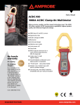
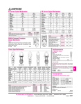
ATGC-1
Ground Coil
Users Manual
Ground Coil
Users Manual
ATGC1_Rev001
© 2008 Amprobe Test Tools.
All rights reserved.
English
ATGC-1
Limited Warranty and Limitation of Liability
Your Amprobe product will be free from defects in material and workmanship for 1 year from
the date of purchase. This warranty does not cover fuses, disposable batteries or damage from
accident, neglect, misuse, alteration, contamination, or abnormal conditions of operation or
handling. Amprobe’s warranty obligation is limited, at Amprobe’s option, to refund of the
purchase price, free of charge repair, or replacement of a defective product . Resellers are not
authorized to extend any other warranty on Amprobe’s behalf. To obtain service during the
warranty period, return the product with proof of purchase to an authorized Amprobe Test
Tools Service Center or to an Amprobe dealer or distributor. See Repair Section for details. This
warranty is your only remedy . All other warranties - whether express, implied or statutory including implied warranties of fitness for a particular purpose or merchantability, are hereby
excluded. Neither Amprobe nor its parent company or affiliates shall be liable for any special,
indirect, incidental or consequential damages or losses, arising from any cause or theory. Since
some states or countries do not allow the exclusion or limitation of an implied warranty or of
incidental or consequential damages, this limitation of liability may not apply to you.
Repair
All test tools returned for warranty or non-warranty repair or for calibration should be
accompanied by the following: your name, company’s name, address, telephone number, and
proof of purchase. Additionally, please include a brief description of the problem or the service
requested and include the test leads with the meter. Non-warranty repair or replacement charges
should be remitted in the form of a check, a money order, credit card with expiration date, or a
purchase order made payable to Amprobe® Test Tools.
In-Warranty Repairs and Replacement – All Countries
Please read the warranty statement and check your battery before requesting repair. During
the warranty period any defective test tool can be returned to your Amprobe® Test Tools
distributor for an exchange for the same or like product. Please check the “Where to Buy”
section on www.amprobe.com for a list of distributors near you. Additionally, in the United
States and Canada In-Warranty repair and replacement units can also be sent to a Amprobe®
Test Tools Service Center (see below for address).
Non-Warranty Repairs and Replacement – US and Canada
Non-warranty repairs in the United States and Canada should be sent to a Amprobe® Test
Tools Service Center. Call Amprobe® Test Tools or inquire at your point of purchase for current
repair and replacement rates.
In USA In Canada
Amprobe Test Tools Everett, WA 98203 Tel: 877-993-5853 Fax: 425-446-6390 Amprobe Test Tools
Mississauga, ON L4Z 1X9
Tel: 905-890-7600
Fax: 905-890-6866
Non-Warranty Repairs and Replacement – Europe
European non-warranty units can be replaced by your Amprobe® Test Tools distributor for a
nominal charge. Please check the “Where to Buy” section on www.amprobe.com for a list of
distributors near you.
European Correspondence Address*
Amprobe® Test Tools Europe
Beha-Amprobe GmbH
In den Engematten 14
79286 Glottertal, Germany
Tel.: +49 (0) 7684 8009 – 0
*(Correspondence only – no repair or replacement available from this address. European customers
please contact your distributor.)
2
Ground Coil for use with Advanced
Wire Tracers AT-2000 and
AT-4000CON Series
3
ATGC-1
Ground Coil
Contents
Symbols..............................................................................................................................................5
Unpacking and Inspection................................................................................................................5
Description.........................................................................................................................................5
Setup and Inductively Coupled Signals............................................................................................5
Tracing Underground Conductors, Water Pipes and Gas Pipes......................................................6
Setup.............................................................................................................................................6
Finding the Conductor(s).............................................................................................................6
Positioning Coil for best signal Induction..................................................................................6
Technical Specifications....................................................................................................................7
4
Symbols
�
Battery
�
Refer to the manual
�
Double insulated
�
Dangerous Voltage
�
Direct Current
�
Earth Ground
�
Alternating Current
�
Audible tone
�
Conforms to relevant Australian
standards.
�
Complies with EU directives
�
Do not dispose of this product as
unsorted municipal waste.
�
Underwriters Laboratories.
�
Application around and removal
from hazardous live conductors
is permitted
Unpacking and Inspection
1x ATGC-1 Ground Coil
1X User’s Manual
Description
The ATGC-1 Ground Coil (Fig. 1) allows the signal from the Transmitter in the Advanced Tracer
AT2000 and AT-4005CON series to be induced onto buried conductors, water pipes, and gas
pipes up to 6 feet deep. This allows tracing of conductors up to 300 feet in length.
Setup and Inductively Coupled Signals
The initial setup of the ATGC-1 to achieve maximum signal induction is accomplished easier
if two people participate. One person to hold the receiver and one person to adjust the coil
position.
Since the ATGC-1 creates a large field, it is possible that the field may be induced onto
other known or unknown conductors in the area. By rewinding or recoiling the ATGC-1 so
the overall diameter of the coil is smaller, the field will become smaller and may eliminate
coupling to adjacent conductors in the area.
The conductor with the lowest resistance, has the most current flowing through it or has the
largest mass, will carry the greatest signal. Underground conductors must be grounded on
both ends or have current flowing through them in order for a signal current to flow. The
Receiver must be set to the “Short” mode in order to sense this signal.
The Receiver should only be set to the “OPEN” MODE if the conductor is not grounded on
both ends and no earth shield is present between the conductor and receiver.
5
� WARNING
If the Receiver does not pick up a signal it does not necessarily mean that the area is safe
for excavating. It is possible that live conductors that do not have current flowing through
them or are not grounded at both ends, do not effectively couple the signal. Extra measures
should be taken to insure that a safety hazard does not exist before any excavating begins.
It is advisable to use the Rechargeable Battery Pack Model B2024 when using the Ground Coil
as it allows a deeper and three times more signal to be induced for longer tracing distances.
Placing the coil directly over the conductor is not recommended, as minimal signal induction
will occur.
Tracing Underground Conductors, Water Pipes and Gas Pipes
Setup
1. Look around and observe your surroundings. Setup the coil in the area that the conductor
most likely would be buried, approximately 30’ away from where you want to start
identifying the location of the conductor.
2. Arrange the ATGC-1 Ground Coil in a circle on the ground approximately 3’ from the top
center of the conductor or pipe (Fig. 2). Note: Placing the coil directly over the conductor
will not induce any signal.
3. Plug the ATGC-1 Ground Coil (A) and B2024 Battery Pack (D) into the Transmitter (E).
4. Set the Transmitter to the “HIGH” MODE and turn the unit “ON”.
5. At a distance of 25–30 ft from the coil, point the Receiver (C) perpendicular to the ground
with the front label and Signal Strength Indicator facing the coil. If you do not get far
enough away from the coil, the receiver will only pick up the signal radiating through the
air off the coil itself.
6. Set the Receiver to the “SHORT” MODE and set the Range selector switch to X100
(AT-2000 series only).
7. Turn the Receiver on by rotating the thumbwheel and set it to 5 (AT-2000 series only).
Finding the Conductor(s)
8. While maintaining a 25–30 ft radius from the coil, trace the area in a circular pattern,
remembering to keep the Receiver perpendicular to the ground with the front label and
Signal Strength Indicator facing the coils as you are circling the coil (Fig. 3). Individual
short “ghost” signals may be received while moving in this circular direction. This is
normal and due to stray signal current. If you stop moving you will realize that there is
no real signal present. The real signal radiating off the conductor will continually pulse.
Multiple signals may indicate multiple conductors. Locate the area in which the maximum
signal strength is displayed on the conductor you wish to trace
Positioning Coil for best signal Induction
9. When the area of the maximum signal is located, place the Receiver (E) probe tip against
the ground on the centerline (D) of the conductor (F). With the Receiver held in place,
have your partner incrementally adjust the position of the ground coil to the left or right
of its original position to further increase the signal strength displayed on the Receiver.
Adjust the sensitivity down if the Receiver full scale deflects.
10.Once the coil is positioned to induce the absolute maximum signal. You may turn from
the coil and begin tracing the conductor away from the calibration point, by moving the
receiver back and forth in a pendulum motion, adjusting the sensitivity as necessary. Mark
the ground with paint or chalk where the maximum signal is received.
6
Remember to keep the receiver tip straight down, perpendicular to the ground with
the front label and signal strength indictor facing the direction of the conductor run. To
trace pipes or conductors over long distances, move the coil to the place where the signal
dropped off and repeat the procedure.
Technical Specifications
Coil Diameter
1m (3.28 ft)
Operating Frequency
32.758 kHz
Field Radius (air)
7.62–9.14m (25–30 ft) With B2024
Termination
Shrouded Male Banana Plugs (Integrated)
Operating Temperature 32˚–120˚F (0˚–48.8˚C)
Weight
0.68 kg (1.5 lbs)
7
A ATGC-1 Ground Coil
D B2024 Battery Pack
B Conductor or Pipe
E Transmitter
C Receiver
F Top Center of conductor
or pipe
Fig. 2 – Proper distance for initial setup.
A ATGC-1 Ground Coil
C Maximum Signal Strength
B Conductor or Pipe
D Little or no signal strength
Fig. 3 – Locating the area of maximum signal strength
8
A Maximum induction
D Conductor Centerline
B Less induction
E Face Receiver towards coil
C Calibration Point
F Conductor
Fig. 4 – Conductor centerline and Coil position adjustment
9
10
Visit www.Amprobe.com for
•Catalog
•Application notes
•Product specifications
•User manuals
Please Recycle