1
- 69 -
LEON2 XST User’s Manual
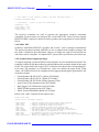
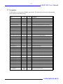
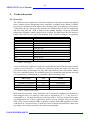
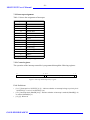
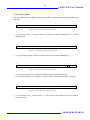
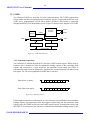
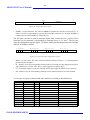
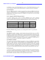
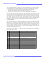
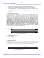
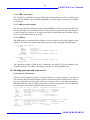
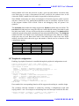
• 2: Transmitter hold register empty (TH) - indicates that the transmitter hold register is empty.
• 4: Overrun (OV) - indicates that one or more character have been lost due to overrun.
• 6: Framing error (FE) - indicates that a framing error was detected.
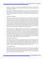
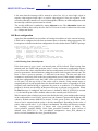
11.3.4 Baud rate generation
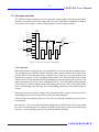
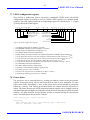
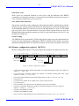
The UART contains a 18-bit down-counting scaler to generate the desired baud-rate. The
scaler is clocked by the system clock and generates a UART tick each time it underflows. The
scaler is reloaded with the value of the UART scaler reload register after each underflow. The
resulting UART tick frequency should be 8 times the desired baud-rate.
If not programmed by software, the baud rate will be automatically be discovered. This is
done by searching for the shortest period between two falling edges of the received data
(corresponding to two bit periods). When three identical two-bit periods has been found, the
corresponding scaler reload value is latched into the reload register, and the BL bit is set in
the UART control register. If the BL bit is reset by software, the baud rate discovery process
is restarted. The baud-rate discovery is also restarted when a ‘break’ or framing error is
detected by the receiver, allowing to change to baudrate from the external transmitter. For
proper baudrate detection, the value 0x55 should be transmitted to the receiver after reset or
after sending break.
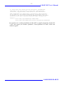
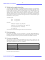
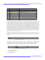
The best scaler value for manually programming the baudrate can be calculated as follows:
scaler = (((system_clk*10)/(baudrate*8))-5)/10
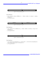
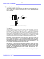
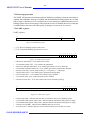
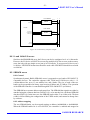
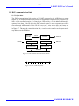
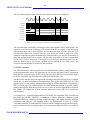
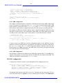
31
14 13
RESERVED
0
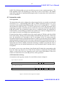
SCALER RELOAD VALUE
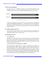
Figure 60: DSU UART scaler reload register
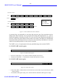
11.4 Common operations
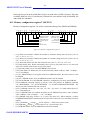
11.4.1 Instruction breakpoints
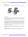
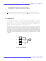
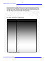
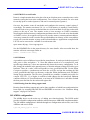
Instruction breakpoints can be inserted by writing the breakpoint instruction (ta 1) to the
desired memory address (software breakpoint) or using any of the four integer unit hardware
breakpoints. Since cache snooping is only done on the data cache, the instruction cache must
be flushed after the insertion or removal of software breakpoints. To minimize the influence
on execution, it is enough to clear the corresponding instruction cache tag valid bit (which is
accessible through the DSU).
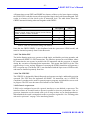
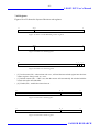
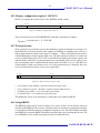
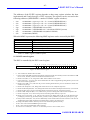
The two DSU hardware breakpoints should only be used to freeze the trace buffer, and not
for software debugging since there is a 4-instruction delay from the breakpoint hit before the
processor enters the debug mode.
GAISLER RESEARCH