1
Perigee Power Solutions
Solar Power Kit User Manual
Step 3
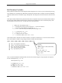
Checking Battery Condition
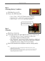
With Main Power to ON.
Observe the LED Status Bar.
o Low (1-3 bars = 10.0V-10.5V, Batteries must be charged)
o Normal (4-7 bars = 10.6V-12.5V, normal operating range)
o Max (8-10 bars = 12.6V-14.5V, max battery capacity)
“Solar In” LED shows quality of charge
(brighter the LED the higher the charge
rate). The black \ red connector on the panel
to kit cable is called an Anderson connector.
Step 4
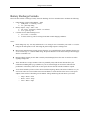
Charging
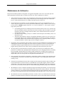
Main Power Switch On.
Connect the panel to kit cable Anderson side to the “Solar In” port.
o All Perigee kits use “keyed” connectors so that cross
connections cannot be mistakenly made.
o The “Multi-port” may be used to daisy chain kits or additional
battery packs to your kit. It may also be used with a voltmeter
to obtain the precise voltage level of your battery.
Solar LED illuminates Red (brightness indicates charge quality).
Notes:
1. Always turn the power switch on when applying a charge from any source. See the
maintenance section for details.
2. When not using your kit, switch off the main power. This will increase the lifespan of the
battery and prevent potential cell damage from over drain. You may remove the fuse to
facilitate a hard disconnect if so desired.
-4-