1
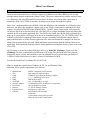
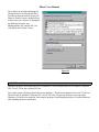
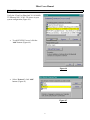
Orion FBoot Software
Users Manual
Document # 98-35783-00 Rev 1.1 02/25/2002
FBoot Users Manual
This page is intentionally left blank.
2
FBoot Users Manual
Table of Contents
1.0
2.0
2.1
2.1.1
2.1.2
2.2
2.2.1
2.2.2
2.2.3
2.2.4
2.3
2.4
2.4.1
2.4.2
2.5
3.0
Introduction
FBoot Installation
Ethernet Card Installation
Check Current NIC Configuration
NIC Installation
Windows Network Configuration Procedure
Add Protocols
Remove TCP/IP From FlexStar Client NIC
Check Bindings of the FlexStar Client NIC
Remove IPX/SPX and 32-bit DLC From Building / Public NIC
Copy Client Image Files to FBoot Service Folder
FBoot Operation
The Following Procedure Sets Up FBoot For Identically…
The Following Procedure Sets Up FBoot For Differently…
Connecting the Server to the Clients
Orion Host Application Settings
3
4
5
6
6
7
8
9
11
12
14
16
18
18
21
24
25
FBoot Users Manual
1.0 Introduction
The Flexstar Remote Boot Service (FBoot) consists of a Windows-based host (RPL File Server) and
multiple remote diskless workstations (Orion Clients). The Server communicates with the remote Clients
via a Ethernet LAN using RPL and IPX protocol stacks. In theory, this scheme allows the clients to
download a DOS, OS/2, UNIX or any other operating system image that might be required.
Each client’s motherboard has special BIOS, which has RPL Boot code embedded in it. When the client
first boots, the Boot code attempts to connect to the server. When a connection is established, the client
requests a download of the RPL loader (RBOOT.RPL). The RPL loader, when loaded, will request the
OS specific files from a specified Image file. The Image file is a single monolithic floppy disk image that
contains the OS and various application files. The OS files are loaded into a RAM drive (solid state drive
made up of system RAM), which appears to the OS as a standard hard drive. The ‘AUTOEXEC.BAT’ file
is then executed which contains an instruction to execute a secondary batch file that contains the file
names and directories of all the Flexstar application files. After this download is complete, the Flexstar
client software application is executed which establishes communication with the Flexstar Orion server
application. Each connected client logs into the Orion application and displays an active status icon on the
server GUI.
The OS image is created by using a third-party utility (e.g. DOSGEN, WinImage). Some tools like
WinImage will allow creation and/or modification of the image file without the need for a physical
floppy disk, and as a result, the has ability to use non-standard sizes of a pseudo-disk (not limited of
1.44M or 2.88M). Notice however, there is a finite OS limitation of 4 M/B.
See also the Orion Host User Manual P/N 98-36391-00.
FBoot is designed to operate under Windows 98, NT 4.0, and Windows 2000.
Minimum Server system requirements are as follows:
•
•
•
•
•
•
•
•
•
•
•
Motherboard:
CPU:
RAM:
FDD:
HDD:
CD-ROM:
Network Adapter:
Key Board:
Monitor:
Pointing Device:
Software:
IBM PC compatible w/PCI interface.
Intel Pentium 1GigHz or higher.
128MB-PC100 compliant memory or higher.
3”½ - 1.44MB floppy disk drive.
IDE-20GB or larger.
48x - CD-ROM drive or better.
3COM Ethernet PCI 10/100BaseT, or equivalent.
101/105 English key board.
15” SVGA monitor or better.
MS-Mouse or equivalent.
MS-Windows OS (98, 2000).
Orion Host.
Client software image files up to date.
FBoot files up to date, image loader.
4
FBoot Users Manual
2.0 FBoot Installation
FBoot software is distributed on a CD-ROM along with the Orion server software. Consult with Technical
Support for latest version and or special instructions. Use the following steps to install FBoot:
•
•
•
•
•
•
If FBoot was previously installed, uninstall it. Delete the Boot Services directory. If you wish to
save any files in this directory move them to another location. NOTE: If you don’t do this step you
will have two Boot Service directories. This will cause problems later on.
Insert the FlexStar Software installation disk into the CD-ROM drive.
Run D:\FBoot\Setup.exe, by double clicking on its icon. D is the drive designator for the CDROM.
Follow the prompt to finish installation. The default installation directory is C:\Program
Files\FlexStar\BootService. See figure #12.
Make a shortcut to ‘FBoot.exe’ by right clicking on its icon then select ‘Create Shortcut’. A new
shortcut will be created in the same directory.
Click on the new icon just created, hold down the mouse button and drag it to the desktop and let
go. Double click this shortcut icon anytime you want to run FBoot application.
5
FBoot Users Manual
2.1 Ethernet Card Installation
NOTE:
This shows a typical system that has a “3Com EtherLink XL COMBO 10Mb Ethernet NIC”. Your server
may have a different brand or model NIC to communicate with other systems in your building and
beyond. We will refer to this NIC as the Building/public NIC. In the steps here a “3Com Fast EtherLink
XL 10/100Mb TX Ethernet NIC (3C905-TX)” is being added to the server for the Flexstar Client’s NIC.
2.1.1 Check Current NIC Configuration
•
To help understand the installation
process, go to Start, Settings, and
Control Panel. The following
window should appear. Double
click on Networks (Figure #1).
Figure #1
6
FBoot Users Manual
The window on the right should appear.
The hardware devices listed will likely
be different than shown here (Figure #2).
Observe what devices are displayed here.
In later steps you will have to distinguish
the difference between your
Building\Public NIC and the NIC you
will add for the FlexStar Clients.
Figure #2
2.1.2 NIC Installation
Shutdown Windows and turn off the server. Install the 3Com Fast EtherLink XL 10/100Mb TX Ethernet
NIC (3C905-TX) in any available PCI slot.
Turn on the system. Windows should detect new hardware. This detection should occur to the 3Com Fast
EtherLink XL 10/100Mb TX Ethernet NIC (3C905-TX) only. If required, Windows may request the
Windows CD-ROM to be installed. Following the prompt to finish installing the driver. Restart Windows
after finishing the driver installation.
7
FBoot Users Manual
2.2 Windows Network Configuration Procedure
This process will be adding Protocols to the Network Interface Card used by the Flexstar Client as follows:
1. Add IPX/SPX-compatible Protocol to the Flexstar Client’s NIC and Microsoft 32-bit DLC to the
FlexStar Client’s NIC.
2. Remove TCP/IP from FlexStar Client NIC
3. Check Binding of the FlexStar Client’s NIC.
4. Remove IPX/SPX and 32 Bit DLC Protocols from Building/public NIC.
Use the following steps to configure Windows networking and to connect the network cards to the
Flexstar clients:
•
•
Click on “Start” button on the
Windows tool bar. Select
“Settings” and then “Control
Panel” and click once.
Double click on ‘Network’ icon
under “Control Panel” (Figure #3).
Figure #3
8
FBoot Users Manual
2.2.1 Add Protocols
Verify the 3Com Fast EtherLink XL 10/100Mb
TX Ethernet NIC (3C905-TX) shows in your
system configuration (Figure #4).
•
To add IPX/SPX Protocol click the
‘Add’ button. (Figure #4)
Figure #4
•
Select ‘Protocol’, click ‘Add’
button. (Figure #5)
Figure #5
9
FBoot Users Manual
•
•
Select ‘Microsoft’,
highlight ‘IPX/SPXcompatible Protocol’
Click ‘OK’ button. (Figure
#6)
Figure #6
•
•
•
Add Microsoft 32-bit DLC
protocol by clicking on
‘Add’ button (Figure # 4)
Select ‘Protocol’, click
‘Add’ (Figure # 5),
Select ‘Microsoft’,
highlight ‘Microsoft 32-bit
DLC’ then click ‘OK’
button (Figure #7).
Figure #7
If you are using Windows 95, make sure the OS has the latest DLC upgrade (you can get the upgrade
from the Microsoft web site)
10
FBoot Users Manual
2.2.2 Remove TCP/IP From FlexStar Client NIC
•
•
On the Configuration window scroll
down to locate and Select TCP/IP ->
3Com Fast EtherLink XL 10/100 Mb
TX Ethernet NIC (3C905-TX).
Click the Remove button (Figure #8).
Figure #8
11
FBoot Users Manual
2.2.3 Check Bindings of the FlexStar Client NIC
•
•
Check the bindings the 3Com Fast EtherLink XL 10/100Mb TX Ethernet NIC (3C905-TX) by
highlighting the Host Bus Adapter.
Click on ‘Properties’ button (Figure #9).
Figure #9
12
FBoot Users Manual
•
Click on the ‘Binding’ tab, verify a check mark on ‘IPX/SPX-compatible Protocol’ and
‘Microsoft 32-bit DLC’. All these protocols are required for the FlexStar Client NIC card (Figure
#10).
Figure #10
13
FBoot Users Manual
2.2.4 Remove IPX/SPX and 32-bit DLC From Building/Public NIC
Check the Building/public Network Configuration card (Figure #11). The Building/public NIC is the
3Com EtherLink XL COMBO 10Mb Ethernet NIC. Notice the IPX/SPX compatible Protocol is shown for
both NIC cards.
• Highlight the “IPX/SPX-compatible Protocol -> 3Com EtherLink XL COMBO” card
• Click Remove.
Figure #11
14
FBoot Users Manual
•
•
Highlight Microsoft 32-bit DLC -> 3Com EtherLink XL COMBO 10Mb Ethernet NIC
Click Remove (Figure #12).
Figure #12
15
FBoot Users Manual
2.3 Copy Client Image Files to FBoot Service Folder
•
•
Insert the Flexstar Software CD-ROM disk that contains client image file(s) into the CD-ROM
drive.
Copy image file(s) to C:\Program Files\Flexstar\BootService\. See figure #13.
Figure #13
Note: Although there are over 30 possible configurations, your CD will only contain the files you need for your
system. The name of the image file describes the port’s configuration. Below is an explanation of the Client
image file naming convention.
16
FBoot Users Manual
Client Image File Naming Convention
With the release of the Pegasus SBC, it was necessary to create individualized Client configuration image
files.
We now support many different hardware configurations, two different SBC, multiple host bus adapters,
both single and multiple drives under test (DUT’s), multiple Power Margin boards, and different sources
to drive the LEDs.
The Pegasus requires a different communication protocol because of the LAN hardware differences. This
is backwards compatible for Orion single board computers (SBCs), however it means removing the
NE2000 from your system or disabling it.
The file naming convention is a description of the Orion hardware configuration of the system, and an
abbreviated version of the client code. This applies to all systems, regardless of the number of test ports.
The full convention will be as follows:
SBC, HBA(# of DUT), REV, Protocol, PwrType, LED sources.
Example
P-ATA4-148-O-NPM4-P.ima
Example
O-SCSI-1113-N-2450-R.ima
SBC
O=Orion
P=Pegasus
PS=Pegasus with on-board SCSI
PSA=Pegasus with on-board SCSI & ATA
HBA
SCSI= SCSI2, SCSI3 or SCSI4
ATA= UDMA66, UDMA100, UDMA133, or SATA
FC=FCAL
# of DUTs
none =1
2=2 supported (applies to Pegasus)
Revision #
O=ODI
N=NonODI
NPM
PC104
2450
R=Riser
P=Power card.
REV
Protocol
PwrType
LED source
17
FBoot Users Manual
2.4 FBoot Operation
FBoot can be set up to download one image file to all Clients without concern of the MAC address.
As in the case where all ports in the system are identical.
FBoot can also be setup to download a specific image file to a particular MAC address. This condition
is required where the system is using more than one type of HBA at the same time.
2.4.1 The following procedure sets up FBoot for identically configured ports.
•
Double click on the icon ‘Shortcut to FBoot.exe’ to open the Flexstar FBoot service. Figure #14.
Figure #14
18
FBoot Users Manual
•
Click on ‘Options’ menu. Select ‘User Settings’. See figure #15.
Figure #15
•
•
•
•
Slide the Needle to adjust the number of ports/clients to the required system size.
Make a check mark in ‘User Override Image File’ box.
Click on the Down arrow button to select the appropriate image to be downloaded to the clients.
Click the ‘OK’ button. See figures #16 & 17.
Figure #16
19
FBoot Users Manual
The FBoot GUI now shows Override ACTIVE and the name of the image file that will be used to
download to the Clients (Figure #17).
Figure #17
20
FBoot Users Manual
2.4.2 The following procedure sets up FBoot for differently configured ports.
•
•
•
•
•
Open FBoot and click on the Clear All Button. Refer to figure 15 and 16.
Click on Options, select User Settings,
Slide the Needle to adjust the number of ports/clients to the required system size.
Turn power on to the system and wait about two minutes.
Click the Refresh Button. The clients should (register) show on the main window (Figure #18).
Figure #18
21
FBoot Users Manual
Find the MAC address that matches the Client tray or pallet for Port 0. Go to the Node Address window
and click on the down arrow button. Select the MAC address for Port 0. Click on the Slot window and
enter “000” for Port 0. Move the mouse to the Image File Name window and Click on the down arrow
button and select the image file which matches the hardware configuration of Port 0. Click the Add
Button (Figure #19).
Figure #19
22
FBoot Users Manual
•
•
•
Repeat the step above for each of the remaining ports, incrementing the Slot number to match the
Port number.
Reset each port in the system or power down the entire system for 60 seconds and power up
again.
The Clients should now boot with the proper image file (Figure #20).
NOTE: The order in which the MAC address appear is random and takes a slot number starting at one
greater than system size set in the options window. When slot number is assigned, the MAC addresses
will appear in the assigned order. When FBoot is closed and re-opened, only the assigned slots will
appear.
Figure #20
23
FBoot Users Manual
2.5 Connecting the Server to the Clients
The server network cards are connected to the client Ethernet hubs using CAT 5 cable. Use the following
instructions to connect these cables:
•
Connect a CAT 5 cable to the FlexStar client Ethernet card (into the RJ45 connector).
•
Connect the other end into the RJ45 connector on the FlexStar system.
Note: When connecting a Solo directly to a server, use the reversing cable (supplied). The reversing
cable is distinguished by having a tape marker on both ends.
•
Turn the test system power switch to OFF, wait for about 60 seconds then turn the power switch
back ON. This will cause all clients to re-boot and will download the new image file. An alternate
method is to manually reset each test port by depressing the RESET button on the back of each
SBC tray in the rear area of the system.
The Image File specified in the FBoot User Settings will be downloaded to each Client.
24
FBoot Users Manual
3.0 Orion Host Application Settings
The following instructions refer to the process where the host software is setup to recognize the location
of each MAC address.
•
A floppy is supplied in the ship kit with each system. It contains a file named “O25Host.ini”.
Copy this file into the Orion directory after installing the host software (Figure #21).
Figure #21
Refer to Orion Host user’s manual for host operations.
25