1
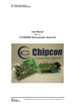
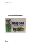
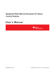
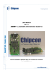
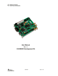
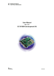
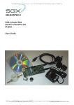
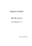
User Manual
Rev. 1.2
CC2400DBK Demonstration Board Kit
SWRU048
Page 1 of 30
Table of contents
INTRODUCTION ....................................................................................................................... 3
PCB ........................................................................................................................................... 4
RF SECTION ............................................................................................................................ 4
ANTENNA ................................................................................................................................. 4
POWER SUPPLY SECTION .......................................................................................................... 7
RS-232 INTERFACE .................................................................................................................. 8
MICROCONTROLLER AND USER INTERFACE ................................................................................ 8
PCB LAYOUT ......................................................................................................................... 11
USING THE CC2400DB DEMONSTRATION BOARD .......................................................... 22
CC2400 SOFTWARE DOWNLOAD AND EVALUATION USING AVR STUDIO 4 ................................. 22
RC OSCILLATOR ..................................................................................................................... 23
MICROCONTROLLER EEPROM MAPPING ................................................................................. 23
IN SYSTEM PROGRAMMING ..................................................................................................... 24
BOOTLOADER ......................................................................................................................... 25
INTRODUCTION TO EXAMPLES PROVIDED WITH CC2400DB ...................................................... 26
SETTING UP A SOFTWARE PROJECT FOR CC2400 .................................................................... 27
HARDWARE DEFINITION FILES (HDF) ...................................................................................... 27
HARDWARE LIBRARY FILES (HLF)........................................................................................... 27
CONFIGURE OUTPUT PROFILE.................................................................................................. 28
DATA PACKET DESCRIPTION .................................................................................................... 28
DATA TRANSMISSION PROTOCOL ............................................................................................. 28
TROUBLESHOOTING ............................................................................................................ 29
IT DOES NOT WORK ................................................................................................................. 29
I CANNOT PROGRAM THE AVR USING THE SERIAL PORT ............................................................ 29
REFERENCES ........................................................................................................................ 29
SWRU048
Page 2 of 30
Introduction
The CC2400 single-chip RF transceiver provides a highly integrated, flexible low-cost solution
for applications using the world wide unlicensed 2.4 GHz frequency band. The CC2400DBK
demonstration board kit is a complement to the development kit (DK) as the hardware is
representative of an actual application, and it is well suited as a prototyping platform for
application code.
The CC2400DBK Demonstration Board Kit includes two CC2400DB Demonstration Boards.
These boards contain a CC2400 with necessary support components, an Atmel mega8 AVR
microcontroller, a PCB antenna, as well as a joystick, buttons and LEDs that can be used to
implement a visual user application interface. The demonstration board is also furnished with
connectors where all of the internal signals on the PCB are available.
This User Manual describes how to use the CC2400DBK Demonstration Board Kit. Atmel’s
AVR Studio and associated software is used to program and debug software. Please see the
reference section of this document for links to Atmel’s documentation on how to use their
tools.
Your CC2400DBK Demonstration Board Kit should contain the following items:
Kit contents
Item
Number of articles
Demonstration Board (CC2400DB)
2
Quick Start instructions
1
CC2400 sample kit
1
RS-232 cables
2
Important:
Contact your local telecommunication authorities before transmitting an RF signal to ensure
that there are no local restrictions on the use of the 2400 –2483.5 MHz ISM band. The
CC2400 operates in the 2.4 GHz frequency band. Although this frequency band is usually
described as “world-wide”, some countries do not allow unlicensed operation in this band.
SWRU048
Page 3 of 30
PCB
Figure 1 depicts an overview of the CC2400DB with description of the various components
embedded on the PCB.
Joystick
MCU
section
RS-232
port
PCB
antenna
4-10 V
DC-jack
CC2400 RF
section
buttons
3.3V voltage
regulator
1.8V voltage
regulator
Optional 9V
battery
Leds
Temp. sensor
Figure 1: CC2400DB overview
RF Section
The CC2400DB RF section includes all the necessary components for correct operation. The
CC2400 is connected to a 16 MHz crystal. A small 2.4 GHz PCB antenna is also included. RF
test and measurement equipment can be mounted the PCB by the use of an SMA connector,
by swapping capacitor placement of C63 and C62. See schematics for details. The RF layout
is identical to the CC2400EM, which is part of the CC2400DK Development Kit.
Important:
The CC2400DB demonstration board output power must be reduced for a 100% transmission
nd
duty cycle to be compliant with the FCC 15 2 harmonics regulation requirement. At the
moment the design is 1 dB above the limit.
Antenna
The PCB antenna is a so-called Inverted-F type. The Inverted-F antenna is a wire monopole
where the top section is folded down to be parallel with the ground plane. By folding the
antenna down you will reduce the height and maintain a resonant wire length. A capacitance
will be introduced to the input impedance of the antenna due to the parallel section. However,
as a rule of thumb design guide, the length + height (L+H) will be approximately equal to a
SWRU048
Page 4 of 30
quarter wavelength (λ/4). A reduction of the antenna height (H) will in general decrease the
antenna bandwidth. Please see figure 3 for the antenna dimensions.
Figure 2: Antenna dimensions
The height of the antenna is defined as the distance from the ground plane to the parallel
section, and the length is from the end of the antenna parallel section to the feed point.
Length: L = (26.19 mm – 9.19 mm + 1.22 mm x ½) = 17.61 mm
Height: H = (6.17 mm + 0.97 mm - 1.19 mm x ½) = 6.55 mm
Quarter wavelength: λ/4 = (L + H) = 17.61 mm + 6.55 mm = 24.16 mm
The physical size of the antenna is decreased somewhat compared to the theoretical length,
(λ = c/4*f = 3x10⁸ / 4x2.45x109) = 30.61 mm
SWRU048
Page 5 of 30
The radiated pattern for the PCB antenna was measured with the horizontal polarization
direction for the CC2400DB by measuring with vertical and horizontal mounting of the
demonstration board.
Important:
In practical range testing outdoors with line-of-sight (LOS) and use of the rfBlinkLed
application example, the following range has been verified at Chipcon Norway with optimal
SmartRF Studio settings for the respective data rates:
1. Data rate settings 1 Mbps, range measured: 140 meters
2. Data rate settings 250 kbps, range measured: 240 meters
Please note that these range tests were performed at 0° C with a simple packet protocol, no
link margin, no robust protocol, close to the sensitivity limit of CC2400, and no retransmission.
0 degr.
Antenna
CC2400DB
Top view
Figure 3: Radiated pattern horizontal mounting
SWRU048
Page 6 of 30
Figure 3 depicts the antenna pattern while the CC2400DB is mounted horizontally with the
antennas parallel section aligned to the 0 degree direction.
0 degr.
Antenna
CC2400DB
Top view
Figure 4: Radiated antenna pattern vertical mounting
Figure 4 depicts the antenna pattern while the CC2400DB is mounted vertically with the
antennas parallel section aligned to the 0 degree direction.
Power supply section
The power supply section contains two voltage regulators: a 3.3 V regulator for use by the
microcontroller and the I/O pins of the CC2400, and a 1.8 V regulator for powering the
CC2400 core.
A diode prevents permanent damage if wrong polarity is applied to the board. There are two
power connectors; a 2.5mm DC jack-type connector allows you to connect an unregulated
battery eliminator easily (the positive supply is on the center pin), and a connector for a 9V
battery on the bottoms side of the PCB. It is also possible to use 3 or 4 AA or AAA alkaline
cells to power the CC2400DB if a suitable battery pack is used.
SWRU048
Page 7 of 30
RS-232 interface
A serial port is included on the CC2400DB. This port is used when software is programmed
into the AVR MCU using the boot loader, and is also used by several of the example
programs. The port includes support for RTS/CTS-type hardware flow control (handshaking).
Important:
It is important to be aware that maximum data rate for the Atmega8 RS-232 interface on
CC2400DB is 38.4 Kbps due to the use of the internal RC oscillator. Please see the Atmega8
datasheet for a baud rate error overview with the respect to a selected oscillator frequency.
Microcontroller and user interface
The microcontroller used is an AVR Atmega8L from Atmel. This controller has 8 KB of Flash
program memory, 1 KB of SRAM data memory and 512 bytes of non-volatile EEPROM data
memory. The controller runs on its internal oscillator, and is interfaced to the CC2400 via its
built-in SPI interface as well as some general I/O pins.
The MCU is also connected to three LEDs, a joystick and an extra button for user interface
purposes. The different examples use these peripherals differently. An analog temperature
sensor is also included.
An ISP connector is provided for programming the AVR without using the serial port. In this
case an Atmel AVR programmer should be connected to this connector.
All of the I/O pins are connected to footprints for 2 x 10 pin-row connectors. These connectors
are compatible with Agilent logic analyzer probes, and can be used either for testing or for
prototyping. For instance, it is possible to add a daughter board with additional circuitry using
these connectors.
AVR Pin
Number
AVR pin name
Pin usage
I/O connector
1
PD3/INT1
CC2400 DIO/DKT
P4 pin 14
2
PD4/XCK/T0
Yellow LED
P4 pin 7
7
PB6/XTAL1/TOSC
1
Joystick up
P3 pin 9
8
PB7/XTAL2/TOSC
2
Joystick right
P3 pin 7
9
PD5/T1
Joystick down
P3 pin 6
10
PD6/AIN0
Joystick left
P3 pin 3
11
PD7/AIN1
Joystick center push
P3 pin 5
12
PB0/ICP
RS-232 handshaking RTS, push
button
P3 pin 13
13
PB1/OC1A
RS-232 handshaking CTS, Red LED
P3 pin 17
14
PB2/SS/OC1B
CC2400 chip select
P4 pin 13
15
PB3/MOSI/OC2
CC2400 SI, AVR ISP
P4 pin 8
16
PB4/MISO
CC2400 SO, AVR ISP
P4 pin 6
17
PB5/SCK
CC2400 SCK, AVR ISP
P4 pin 4
19
ADC6
Not used
P4 pin 11
22
ADC7
Temperature sensor
P4 pin 9
23
PC0/ADC0
CC2400 GIO6
P4 pin 10
SWRU048
Page 8 of 30
24
PC1/ADC1
CC2400 GIO1
P4 pin 19
25
PC2/ADC2
CC2400 TX
P4 pin 16
26
PC3/ADC3
CC2400 RX
P4 pin 18
27
PC4/ADC4/SDA
RS-232 on/off
P3 pin 11
28
PC5/ADC5/SCL
Green LED
P4 pin 5
29
PC6/RESET
Reset button, AVR ISP
P4 pin 3
30
PD0/RXD
RS-232 receive data from PC
P3 pin 15
31
PD1/TXD
RS-232 transmit data to PC
P3 pin 19
32
PD2/INT0
CC2400 DCLK/FIFO
P4 pin 12
Table 1: AVR I/O pins
SWRU048
Page 9 of 30
Pin
number
Signal name in
schematic
Pin usage
CC2400
pin
AVR pin
1
2
3
Unregulated supply
voltage
PD6
Joystick left
10 (PD6/AIN0)
5
PD7
Joystick center push
11 (PD7/AIN1)
6
PD5
Joystick down
9 (PD5/T1)
7
PB7
Joystick right
8
(PB7/XTAL2/TOSC2)
PB6
Joystick up
7
(PB6/XTAL1/TOSC1)
FORCE_ON
RS-232 on/off
27 (PC4/ADC4/SDA)
RTS
RS-232 handshaking,
push button
12 (PB0/ICP)
RXD0
RS-232 data from PC
30 (PD0/RXD)
CTS
RS-232 handshaking,
Red LED
13 (PB1/OC1A)
19
TXD0
RS-232 data to PC
31 (PD1/TXD)
20
GND
Ground
4
8
9
10
11
12
13
14
15
16
17
18
Table 2: P3 pinout
SWRU048
Page 10 of 30
Pin
number
Signal name in
schematic
Pin usage
CC2400
pin
AVR pin
3
RESET
Reset
4
SCLK
CC2400 serial clock,
AVR ISP
5
PC5
Green LED
6
SO
CC2400 SPI out, AVR
ISP
7
PD4
Yellow LED
8
SI
CC2400 SPI in, AVR
ISP
9
ADC7
Temperature sensor
10
GIO6
CC2400 GIO6
11
ADC6
Not used
12
DCLK/FIFO
CC2400 DCLK/FIFO
30
(DCLK/FIF
O)
32 (PD2/INT0)
13
CSn
CC2400 chip select
31 (CSn)
14 (PB2/SS/OC1B)
14
DIO/PKT
CC2400 DIO/PKT
29
(DIO/PKT)
1 (PD3/INT1)
15
3.3V
3.3V regulated supply
16
TX
CC2400 TX
28 (TX)
25 (PC2/ADC2)
17
1.8V
1.8V regulated supply
18
RX
CC2400 RX
27 (RX)
26 (PC3/ADC3)
19
GIO1
CC2400 GIO1
21 (GIO1)
24 (OC1/ADC1)
20
GND
Ground
1
2
29 (PC6/RESET)
32 (SCLK)
17 (PB5/SCK)
28 (PC5/ADC5/SCL)
34 (SO)
16 (PB4/MISO)
2 (PD4/XCK/T0)
33 (SI)
15 (PB3/MOSI/OC2)
22 (ADC7)
35 (GIO6)
23 (PC0/ADC0)
19 (ADC6)
Table 3: P4 pinout
PCB layout
RF circuits operating at high frequencies are normally sensitive to the physical layout of the
PCB. Chipcon has carefully optimized the layout of the CC2400DB Demonstration Board and
we therefore recommend that our customer copy, at least the RF parts and the decoupling
around the CC2400 when making their own PCB designs.
The PCB is of a 4-layer type in order to provide a well-defined ground plane as well as
adequate routing space. The laminate used is standard FR-4 board material. The PCB is
1.0mm thick, with layer 1 on the topside, layers 2 and 3 are internal layers and layer 4 is on
the bottom side. Layers 1 and 4 are used for routing, while layer 2 is a ground plane and layer
3 is used for power routing. All areas in the RF section that are not utilized for routing are
filled with copper connected to ground to provide RF shielding. The ground planes on all
layers are stitched together with closely spaced vias.
SWRU048
Page 11 of 30
Layer 1
Layer 2
Layer 3
Layer 4
Figure 5: CC2400DB PCB layout
SWRU048
Page 12 of 30
Top Assembly
Bottom Assembly
Figure 6: CC2400DB PCB layout silkscreen
SWRU048
Page 13 of 30
Schematic
Figure 7: CC2400DB schematic page 1
SWRU048
Page 14 of 30
Figure 8: CC2400DB schematic page 2
SWRU048
Page 15 of 30
Figure 9: CC2400DB schematic page 3
SWRU048
Page 16 of 30
Figure 10: CC2400DB schematic page 4
SWRU048
Page 17 of 30
Figure 11: CC2400DB schematic page 5
SWRU048
Page 18 of 30
Bill of materials
Bill of materials, CC2400DB Top-level section
Reference
Description
Value
Part
P1
DC jack, 2.5mm
center pin
DC_JACK_2.5
P2
D-Sub, 9 pin, female
DSUB_9F
P3
PINROW_2X10
Pin row, 2x10
P3
PINROW_2X10
Pin row, 2x10
R101
Resistor 0603
0Ω
Not Mounted
Bill of materials, CC2400DB RF Section
Reference
Description
Value
Part
C1
Capacitor 0603
2.2 uF, 10%
C_2U2_0603_X5R_K_10
C11
Capacitor 0402
100 nF, 10%
C_100N_0402_X5R_K_10
C61
Capacitor 0402
0.5 pF, ± 0.25 pF
C_0P5_0402_NP0_C_50
C62
Capacitor 0402
5.6 pF, ± 0.25 pF
Not Mounted
C63
Capacitor 0402
5.6 pF, ± 0.25 pF
C_5P6_0402_NP0_C_50
C71
Capacitor 0402
100 nF, 10%
C_100N_0402_X5R_K_10
C81
Capacitor 0402
0.5 pF, ± 0.25 pF
C_0P5_0402_NP0_C_50
C101
Capacitor 0402
10 nF, 10%
C_10N_0402_X7R_K_25
C161
Capacitor 0402
68 pF, 5%
C_68P_0402_NP0_J_50
C251
Capacitor 0402
100 nF, 10%
C_100N_0402_X5R_K_10
C261
Capacitor 0402
100 nF, 10%
C_100N_0402_X5R_K_10
C411
Capacitor 0402
68 pF, 5%
C_68P_0402_NP0_J_50
C421
Capacitor 0402
27 pF, 5%
C_27P_0402_NP0_J_50
C431
Capacitor 0402
27 pF, 5%
C_27P_0402_NP0_J_50
C481
Capacitor 0402
68 pF, 5%
C_68P_0402_NP0_J_50
L61
Inductor 0402
7.5 nH, 5%
L_7N5_0402_J
L62
Inductor 0402
5.6 nH, 5%
L_5N6_0402_J
L71
Inductor 0402
27 nH, 5%
L_27N_0402_J
L81
Inductor 0402
7.5 nH, 5%
L_7N5_0402_J
P5
Surface-mount SMA,
straight
R4
Resistor 0402
2.2 Ω, 5%
R2R2_0402_J
R451
Resistor 0402
43 kΩ, 1%
R_43K_0402_F
SMA_SMD
SWRU048
Page 19 of 30
Bill of materials, CC2400DB RF Section
Reference
Description
Value
Part
U1
Single-chip
transceiver
CC2400
X1
Crystal, ceramic
SMD 4x25mm
X_16.000/10/10/10/16 (Toyocom
TSX-10A 16M 16pF)
Note: The crystal X1 mounted on the EM board is a 16.000 MHz crystal, with ±10 ppm initial
tolerance, ± 10 ppm drift over temperature and a temperature range of –10˚ C to +60˚ C. The
crystal is designed for 16 pF load capacitance. In an actual application, the tolerance, drift
and temperature range of the crystal must be considered with application requirements in
mind. Please consult the data sheet and SmartRF® Studio for more information. It is possible
to choose a larger crystal package to save cost. The crystal should have an ESR of 60 Ω or
less.
Bill of materials, CC2400DB MCU section
Reference
Description
Value
Part
C201
Capacitor 0603
100 nF, 10%
C_100N_0603_X7R_K_50
C202
Capacitor 0603
100 nF, 10%
C_100N_0603_X7R_K_50
C203
Capacitor 0603
100 nF, 10%
C_100N_0603_X7R_K_50
C204
Capacitor 0603
33 nF, 10%
C_33N_0603_X7R_K_25
C205
Capacitor 0603
100 nF, 10%
C_100N_0603_X7R_K_50
D2
LED, red, SMD
Red
LED_CL150URCD
D3
LED, yellow, SMD
Yellow
LED_CL150YCD
D4
LED, green, SMD
Green
LED_CL150GCD
L201
EMI filter bead
BLM18AG102SN1D
P6
ISP connector
PINROW_2X3
R201
Resistor 0603
0 Ω, 1%
R_0_0603
R202
Resistor 0603
0 Ω, 1%
R_0_0603
R203
Resistor 0603
0 Ω, 1%
R_0_0603
R204
Resistor 0603
270 Ω, 1%
R_270_0603_J
R205
Resistor 0603
270 Ω, 1%
R_270_0603_J
R206
Resistor 0603
270 Ω, 1%
R_270_0603_J
R207
Resistor 0603
10 kΩ, 1%
R_10K_0603_G
R208
Resistor 0603
10 kΩ, 1%
R_10K_0603_G
S1
Push button, SMD
ALPS-SKHUAF
S2
Push button, SMD
ALPS-SKHUAF
U2
Temperature sensor,
SOT23
LM61
U3
Atmel microcontroller,
MLF32
Atmega8
SWRU048
Page 20 of 30
Bill of materials, CC2400DB MCU section
Reference
Description
U5
4-directional switch
with a center push
Value
Part
skrhab_e010
Bill of materials, CC2400DB Voltage regulator section
Reference
Description
Value
Part
C401
Capacitor 1206
2.2 uF, 10%
C_2U2_1206_X7R_K_10
C402
Capacitor 1206
2.2 uF, 10%
C_2U2_1206_X7R_K_10
C403
Capacitor 0603
33 nF, 10%
C_33N_0603_X7R_K_25
C404
Capacitor 0603
100 nF, 10%
C_100N_0603_X7R_K_50
C405
Capacitor 1206
2.2 uF, 10%
C_2U2_1206_X7R_K_10
D1
Schottkey diode, 2A
20BQ030
P7
9V battery connector
(positive)
CONN_9V_POS
P8
9V battery connector
(negative)
CONN_9V_NEG
U4
3.3V low drop-out
regulator
LP2981IM5-3.3
U6
1.8V low drop-out
regulator
XC6204B182MR
Bill of materials, CC2400DB RS-232 section
Reference
Description
Value
Part
C501
Capacitor 0603
100 nF, 10%
C_100N_0603_X7R_K_50
C502
Capacitor 0603
100 nF, 10%
C_100N_0603_X7R_K_50
C503
Capacitor 0603
100 nF, 10%
C_100N_0603_X7R_K_50
C504
Capacitor 0603
33 nF, 10%
C_33N_0603_X7R_K_25
C505
Capacitor Low
Impedance
470 uF
C_470U_8_CVAX
C506
Capacitor 1206
2.2 uF, 10%
C_2U2_1206_X7R_K_10
C507
Capacitor 0603
100 nF, 10%
C_100N_0603_X7R_K_50
U101
RS-232 Transceiver,
3-5V
MAX3243CWI
Table 4: Bill of materials
SWRU048
Page 21 of 30
Using the CC2400DB Demonstration Board
The CC2400DB Demonstration Board is designed to be useful for quick prototyping, and also
for quick practical evaluation such as range testing.
Software can be programmed into the AVR microcontroller either using an external
programmer such as the AVRISP programmer or using the serial port to communicate with
the boot loader that is programmed into the MCU when the CC2400DB is shipped from the
factory. If the boot loader is overwritten when using an external programmer, the AVR must
be re-programmed with the boot loader before it is possible to program the AVR via the serial
port again.
When shipped from the factory, the CC2400DB contains the boot loader and a simple
example that will transmit a packet when a button is pressed, and blink a LED when a packet
is received. This example is ideal for range testing, for instance.
CC2400 Software download and evaluation using AVR Studio 4
Use a serial cable connecting the serial interface of the CC2400DB to the serial port of a PC
running AVR Studio and SmartRF® Studio. You can then use SmartRF® Studio to find all the
RF parameters for the CC2400 and AVR Studio 4 to control the CC2400DB, development
board.
Power
supply
220V
PC running
AVRStudio
Serial cable
4-10V
Serial cable
CC2400DB
AVRISP
Programmer
Figure 12: Software download using AVR Studio 4
The CC2400DB demonstration board can be used for application software development. To
download new application examples a PC must be communicating with CC2400DB running
AVR Studio. AVR Studio can be downloaded free of charge from the world-wide-web.
The configuration of the processor fuses is only performed through the SPI interface using
the AVRISP programmer and AVR Studio 4. The AVRISP fuse window is depicted in figure
13. The CC2400DB is configured with the following fuses enabled:
1. Boot Flash section size = 512 words Boot start address=$0E00;[BOOTSZ=01]
2. Brown out detection level at VCC = 2.7 V
3. Internal RC oscillator at 8 MHz Start up time 6CK + 0 ms
4. Preserve EEPROM memory through the Chip Erase Cycle
5. Boot vector enabled (default address = $0000)
SWRU048
Page 22 of 30
Figure 13: AVR Studio AVRISP Fuses Window
RC oscillator
The internal RC oscillator is used as reference time base. The oscillator frequency is
relatively independent of temperature and operating voltage. Its nominal frequency is 8 MHz.
A calibration feature utilising a calibration word programmed into the microcontroller at the
factory ensures that the oscillator frequency is equal from unit to unit. The calibration value is
stored at a fixed location in the EEPROM of the processor.
Microcontroller EEPROM mapping
The following map shows the data location. To customize the CC2400DB for a different
frequency, the EEPROM data can be replaced by new values found using the calibration
software. Please contact Chipcon Technical Support.
Note:
If a different RC oscillator frequency is used, a new calibration must be performed for the
desired frequency and stored at the correct location in EEPROM. The bootloader uses the
RS-232, so by changing the frequency the bootloader must be reprogrammed with the correct
baud setting for the frequency of choice. Please contact Chipcon Technical Support
EEPROM
Data
Reference
Comment
Address (hex)
0x01FF
Calibration Value
Calibration value is
only for 8 MHz
SWRU048
Page 23 of 30
Table 5: EEPROM memory map
In System Programming
Using the AVRISP in-circuit programmer or similar devices, the microcontroller can be
reprogrammed. The program code memory (flash) and the EEPROM can be reprogrammed.
AVRISP
Figure 14: AVRISP Program Window used to program flash or EEPROM
The device used for programming must be connected to the CC2400DB programming socket.
The programming interface uses 4 signal lines. These four lines can be accessed at the 6-pin
connector, P6. The pin out and description is listed in the table 5.
Signal/pin
MISO
SCK
MOSI
RESET
VCC
GND
AVR
programming
socket, pin
1
3
4
5
2
6
SWRU048
Page 24 of 30
Table 6: ISP header connector
Bootloader
The CC2400DB is shipped with a bootloader. This loader communicates with AVR Studio.
After reset the bootloader must have a way to determine to start program mode or to run the
application software residing in the application code section of the flash. To start the
bootloader the Joystick center push on CC2400DB is used to enter program mode. This
button his held low after reset while starting the AVR Prog from the Tools menu in AVR
Studio until the bootloader program window is loaded. See figure 15 and 16.
Step-by-Step procedure:
1. Connect the CC2400DB serial port to your PC COM port
2. Connect power to CC2400DB
3. Start AVR Studio
4. Select Tools from the menu (See figure 15)
5. Reset CC2400DB and hold the Joystick Center push button down after reset and
start AVR Prog, bootloader will start (See figure 16)
6. Browse to find your application program *.hex file
7. Click on the Flash Program to program the flash
Important note:
If you should program the EEPROM please contact Chipcon Technical Support
8.
Disconnect serial port
9. Reset CC2400DB
10. Start your application program
Figure 15: Starting AVR Prog in AVR Studio
SWRU048
Page 25 of 30
Figure 16: AVRprog bootloader Window
In the bootloader window the user can browse to the location of his application program and
program the application code section of the flash with the new application. After programming
is successful, reset the processor and the application code will start.
Important:
If the AVRISP programmer is used to program examples, the bootloader will be deleted if no
protection mode is applied to this section of the processor flash. The bootloader is modified
source code from ATMEL AVR application note AVR109, Self programming and compiled
with IAR Embedded Workbench.
Introduction to examples provided with CC2400DB
The CC2400 Development Environment for the development of CC2400 software
applications is a combination of three tools, a text editor of choice e.g. (UltraEdit-32), a
compiler/assembler/linker and software platform provided by the processor manufacturer.
The CC2400 Development Environment is based on the “WinAVR”, which is a software
development tool. The WinAVR (pronounced “whenever”) is a suite of open source software
development tools for the Atmel AVR series of RISC microprocessors for the Windows
platform. It includes the GCC compiler for C and C++. This tool provides a framework for
most of the features supported by the Atmega8 microcontroller used with the CC2400DB
Demonstration Board.
The text editor of choice is primarily a tool for editing C source, assembler and make files.
However, it also provides syntax highlighting and other helpful functionality, such as a GUI
with possibility of project management, and C function highlighting.
Since the compiler/assembler/linker is integrated into another tool the text editor must be
configured with macros to support the make file provide with the for GCC compiler. More
SWRU048
Page 26 of 30
specifically the compiler converts one or more C source files into assembly code, which,
together with any handwritten assembler files are fed to the assembler. The assembler then
produces object files (machine code and binary data), which in turn are fed into the linker
together with the libraries and include files. Finally, the linker isolates functions and variables
that are actually used and produces an executable file in Intel HEX format that can be
downloaded into the FLASH memory of the Atmega8 microcontroller
Setting up a software project for CC2400
Before the CC2400 Development Environment can generate any target software it needs a
software project with consistent references to the actual target platform files is needed. These
references can be specified in the target project workspace of your text editor. See figure 17.
Figure 17: Software project workspace
Hardware Definition Files (HDF)
The hardware definition files (include files) define the hardware registers, interrupt vector
mapping and other hardware constants. They also include useful macros for the CC2400DB,
and all definitions generally support the C language.
The following files are included as hardware definition files,
•
atmega.h
•
CC2400.h
•
devboard.h
•
Utility.h
Hardware Library Files (HLF)
To support quick and easy program development Chipcon provides a library of macros and
functions that simplify hardware access to the CC2400 and the processor on the CC2400DB.
The files implement a hardware abstraction interface for the user program. As a result the
user program can access the e.g. microcontroller peripherals via function/macro calls without
specific knowledge about the hardware details
The following files are included as hardware library files,
•
atmega.c
•
CC2400.c
SWRU048
Page 27 of 30
•
Utility.c
Configure output profile
The CC2400 Development Environment “build process” generates an executable file
according to the settings specified in the make file provided with the application examples
and by using the macros configured in the text editor. To support the processor target the
output file must be in the correct format.
With CC2400DB an RF link example is provided in the application code section of the
processor flash. The example is called rfBlinkLed. The application program is controlled by
the same push button as the bootloader, S2. See schematic layout for location of the button
on the PCB. Instead of powering up the board with the bootloader the board should be
powered up with the application code. The CC2400 is configured with default settings,
buffered mode, and a data rate of 1 Mbps.
Use the S2 push button to start the application. You will see that if you have no receiver up
and running the red LED will start to toggle. This means that you are not receiving
acknowledge form the receiver and thus have no link.
Data packet description
The data packet consists of a preamble, synchronization word, length byte, flag byte and a
data field. The length byte, flag byte and a fixed 10-byte payload are inserted by the
application.
The preamble, synchronization word and CRC is generated and inserted in the package by
CC2400. The data packet is shown in the figure 18.
SOF
Preamble
LENGTH
FLAGS
PAYLOAD
CRC
Inserted by CC2400
Figure 18 The data packet used in the rfBlinkLed example
Data transmission protocol
The data transmission protocol is very simple, only using packet acknowledgement (ACK).
When the receiver receives a data package, the packet type is checked for CRC. If the
message is OK, it is shown on the green receiver LED, and an acknowledgement is sent as a
reply. However, if an acknowledgement packet that is received by the transceiver originally
transmitting, receival of the ACK is indicated on the yellow LED without any further reply. If no
acknowledgement is received the red LED will toggle.
Receiver polling
Initial
trans mission
Message
shown on
receiver LED
Ack.
trans mission
Acknowledge
shown on
Transceiver LED
Device is active as
long as S2 push
button is held down
LED
DEVICE 1
DEVICE 2
RX
TX
LED
TX ACK
RX
LED (ACK)
Figure 19 Data Transmission Protocol
SWRU048
Page 28 of 30
Troubleshooting
It does not work
•
Make sure that the power supply is connected to the correct pins on the power
connector.
•
Is the supply voltage correctly polarized? If not, the protection diode will prevent any
current from flowing. + and – are indicated on the PCB. On the DC jack, the tip is +
and the ring is –.
I cannot program the AVR using the serial port
•
If you have programmed the AVR using an external programmer, you must use an
external programmer to program the AVR with the bootloader before you can use the
serial port to program the AVR again.
References
CC2400 Datasheet
Atmel Application note: AVR109 Self-programming (Bootloader for CC2400DBK is based on
this application note)
http://www.atmel.com/dyn/general/tech_doc.asp?doc_id=8053
AVR Studio:
http://www.avrfreaks.net/Home/News/article.php?NewsID=457
Or
http://www.atmel.com/dyn/products/tools.asp?family_id=607
WINAVR / AVR GCC:
http://www.avrfreaks.net/AVRGCC/index.php
Document History
Revision
Date
Description/Changes
1.0
08.01.2004
Initial release.
1.1
28.01.2004
Cosmetic and bootloader section changes
1.2
13.02.2004
Minor BOM and layout change on CC2400DB
SWRU048
Page 29 of 30
Address Information
Web site:
http://www.chipcon.com
E-mail:
[email protected]
Technical Support E-mail:
[email protected]
Technical Support Hotline:
+47 22 95 85 45
Headquarters:
Chipcon AS
Gaustadalléen 21
NO-0349 Oslo
NORWAY
Tel: +47 22 95 85 44
Fax: +47 22 95 85 46
E-mail: [email protected]
US Offices:
Chipcon Inc., Western US Sales Office
19925 Stevens Creek Blvd.
Cupertino, CA 95014-2358
USA
Tel: +1 408 973 7845
Fax: +1 408 973 7257
Email: [email protected]
Chipcon Inc., Eastern US Sales Office
35 Pinehurst Avenue
Nashua, New Hampshire, 03062
USA
Tel: +1 603 888 1326
Fax: +1 603 888 4239
Email: [email protected]
Sales Office Germany:
Chipcon AS
Riedberghof 3
D-74379 Ingersheim
GERMANY
Tel: +49 7142 9156815
Fax: +49 7142 9156818
Email: [email protected]
Chipcon AS (Strategic Automotive Center)
Hechtseestrasse 16
D-83022 Rosenheim
Germany
Tel: +49 8031 2227 660
Mobile: +49 172 8540 132
Fax: +49 8031 2227 661
Email: [email protected]
Sales Office Asia :
Chipcon Asia Pasific
37F, Asem Tower
159-1 Samsung-dong, Kangnam-ku
Seoul 135-798 Korea
Tel: +82 2 6001 3888
Fax: +82 2 6001 3711
Email: [email protected]
SWRU048
Page 30 of 30