1
Eurotest 61557 MI 2086 User Manual Version 4.2, Code no. 20 750 719 Distributor: Manufacturer: METREL d.d. Ljubljanska cesta 77 1354 Horjul Slovenia web site: http://www.metrel.si e-mail: [email protected] © 2004..2008 METREL Mark on your equipment certifies that this equipment meets the requirements of the EU (European Union) concerning safety and interference causing equipment regulations. No part of this publication may be reproduced or utilized in any form or by any means without permission in writing from METREL. 2 MI 2086 Eurotest Table of contents 1. Introduction.............................................................................................................5 1.1. General description ............................................................................................5 1.2. Warnings ............................................................................................................5 1.3. List of parameters measurable by the Eurotest 61557.......................................6 1.4. Standards applied ..............................................................................................7 2. Instrument description...........................................................................................8 2.1. Front panel .........................................................................................................8 2.2 Connector panel................................................................................................10 2.3. Bottom side ......................................................................................................11 2.4. Standard accessories.......................................................................................12 2.5. Optional accessories ........................................................................................12 2.6. Ways of carrying the instrument.......................................................................12 2.7. Accessories required for specific measurement...............................................13 3. Measurement instructions ...................................................................................14 3.1. Insulation resistance ........................................................................................14 3.2. Varistor Over-voltage Protection Devices ........................................................17 3.3. Continuity of Protective Conductors .................................................................20 3.4. Continuity .........................................................................................................24 3.5. Earth Resistance (internal generator) ..............................................................27 3.6. Specific Earth Resistance ................................................................................34 3.7. PE terminal test................................................................................................37 3.8. RCD - Contact Voltage and Earth / Fault Loop Resistance..............................39 3.9. RCD – Trip-Out Time .......................................................................................43 3.10. RCD – Trip-Out Current .................................................................................46 3.11. RCD – Automatic Test ...................................................................................48 3.12 Fault Loop Impedance and Prospective Short-circuit Current .........................52 3.13. Contact Voltage at Prospective Short-circuit Current .....................................55 3.14. Line Impedance and Prospective Short-circuit Current ..................................57 3.15. N-PE Loop Resistance and Prospective Short-circuit Current .......................59 3.16. Phase rotation ................................................................................................61 3.17. Current ...........................................................................................................63 3.18. Illumination .....................................................................................................66 3.19. Tracing of electric installation .........................................................................68 3.20. Power .............................................................................................................71 3.21. Energy............................................................................................................73 3.22. Harmonics ......................................................................................................75 4. Other operations...................................................................................................78 4.1. Set-up functions ...............................................................................................78 4.2. Creating Installation structure on PC................................................................79 4.3. Storing test results ...........................................................................................81 4.4. Recalling stored test results .............................................................................83 4.5. Erasing stored test results................................................................................84 4.6. Reset of the instrument ....................................................................................86 3 MI 2086 Eurotest Table of contents 5. Maintenance ..........................................................................................................87 5.1. Batteries ...........................................................................................................87 5.2. Fuses ...............................................................................................................88 5.3. Cleaning ...........................................................................................................89 5.4. Periodic calibration...........................................................................................89 5.5. Service .............................................................................................................89 6. Technical specification ........................................................................................90 6.1. Functions..........................................................................................................90 6.2. General characteristics ....................................................................................95 4 MI 2086 Eurotest Introduction 1. Introduction Congratulations on your purchase of the Eurotest 61557 test instrument and it's accessories, produced by METREL d.d. We are glad, to be able to offer high professional test equipment, for carrying out absolute inspection of electric installations in buildings as well as Earth Resistances. The equipment was designed and produced on basis of rich experiences, acquired through more-years long period of dealing with electric installation test equipment. 1.1. General description The Eurotest 61557 is high professional, multifunctional, portable test instrument, intended for carrying out all measurements, according to European standard EN 61557, as well as various other tests and measurements. The instrument is equipped with all accessories, necessary for comfortable carrying out the tests. It is kept in a soft carrying bag, together with all the enclosed accessories. Electronic part of the Eurotest 61557 is produced in SMD technology, which demands practically no service interventions. Wide matrix display with backlight offers easy to read main results as well as wide range of subresults, parameters and messages. Operation is simple and clear; operator does not need any special training (except to read this Instruction Manual) to operate the instrument. In order, the operator to be familiar enough with measurements in general, it is advisable to read the enclosed handbook Measurements on electric installations in theory and practice. Built in a unique system for storing test results is important feature of the Eurotest 61557. Professional PC SW enables simple transfer of test results and other parameters in both directions between the test instrument and PC, as well as automatic forming of final protocols. That way, complete measurement procedure can be reasonably quick and thus, the operator competitive to other operators, who need to create the protocols manually. 1.2. Warnings In order to reach high operator’s safety, while carrying out various measurements and tests using the Eurotest 61557, as well as to keep the test equipment undamaged, it is necessary to consider the following general warnings: If the test equipment is used in manner not specified in this InstructionManual, the protection provided by the equipment may be impaired! 5 MI 2086 Eurotest Introduction Do not use the instrument and accessories, if any damage is noticed! In case of blown any fuse, follow the instructions in this Instruction Manual, to replace it! Service intervention or calibration procedure is allowed to be carried out only by a competent, authorised person! Consider all generally known precautions, in order to avoid risk of electric shock, while dealing with electric installations! Use only standard or optional test cables, supplied by your distributor! 1.3. List of parameters measurable by the Eurotest 61557 Parameter Earth Resistance RE (classic four-lead method) Earth Resistance RE (classic four-lead method + one test clamp) Earth Resistance RE (two test clamps) Earth Resistivity ρ Continuity R of protective conductors Continuity Rx Insulation Resistance Ri Illumination Varistor Breakdown Voltage Ub Leakage Current IL Load Current I Voltage and Current Harmonics up to 21-th Power P, Q, PA, cosϕ Energy W Function switch position R,ρ EARTH R,ρ EARTH R,ρ EARTH R,ρ EARTH R ±200 mA CONTINUITY R ±200 mA CONTINUITY RISO Description - Four test terminals Two test rods Four test terminals Two test rods One test clamp Two test clamps - Four test terminals Four test rods Test current > 200 mAd.c. Single measurement Auto polarity reverse Test current < 7 mA Continuous measurement Test voltages: 50,100,250,500,1000 V SENSOR TEST CURRENT CURRENT HARMONICS POWER ENERGY POWER ENERGY Installation tracing phase rotation / LOCATOR 6 Test voltage 0 ÷ 1000 V Threshold current 1 mA Test clamp Test clamp One phase system Test clamp (current har.) Test tips (voltage har.) One-phase system Current clamp One-phase system Current clamp In combination with hand-held indicator - Line voltage loading or imposing of test signal - MI 2086 Eurotest Phase rotation RCD - Contact Voltage Uc RCD - Trip out Time t RCD - Tripping Current RCD - Earth Resistance RE (external source) RCD - Fault Loop Res. RL Line Impedance ZL-N, ZL-L Line Prospective Short-circuit Current Ipsc Fault Loop Impedance ZL-PE Fault Loop Prospective Short-circuit Current Ipsc Contact Voltage at Prospective Short-circuit Current Uc/Ipsc N-PE Loop Resistance RN-PE Fault Loop Prospective Short-circuit Current Ipsc (without tripping out RCD) Introduction phase rotation / LOCATOR RCD RCD RCD RCD RCD ZLINE ZLINE ZLOOP ZLOOP ZLOOP RLOOP N-PE RLOOP N-PE - With or without test rod - Test rod - No trip out RCD - No trip out RCD - Between L and N or L and L - Between L and N or L and L - Between L and PE - Between L and PE - Test probe - With aux. test probe - No trip out RCD Internal source Between L and PE No trip out RCD 1.4. Standards applied The Eurotest 61557 is designed according to European safety standard ♦ EN 61010 - 1 EMC (noise and immunity) according to European standards ♦ EN 50081 – 1 ♦ EN 50082 – 1 Measurements according to European standard EN 61557: ♦ Insulation Resistance ...................................................................... Part 2 ♦ Loop Impedance ............................................................................. Part 3 ♦ Resistance of earth connection and equipotential bonding ............. Part 4 ♦ Earth Resistance ............................................................................. Part 5 ♦ Residual Current Devices (RCD) in TT and TN systems................. Part 6 ♦ Phase Sequence ............................................................................. Part 7 Illumination measurement accroding to standard DIN 5032 ...........……..Part 7 7 MI 2086 Eurotest Instrument description 2. Instrument description 2.1. Front panel Fig. 1. Front panel 8 MI 2086 Eurotest Instrument description Legend: 1 ON/OFF key, to switch ON or OFF the instrument. Auto OFF will occur automatically 10 minutes after last strike to any key or function switchrotation. 2 HELP key, to display help menu (connection of test leads and other data). 3 Light key, to turn ON or OFF display backlight. Auto OFF will occur automatically 20 seconds after last strike to any key or function switch rotation. 4 RCL key, to recall stored results. 5 SAVE key, to store test results. 6 PE touching electrode, to test PE terminal (presence of phase voltage by mistake). 7 START key, to start any measurement. 8 SETUP key to: ♦ ♦ ♦ ♦ Set display contrast. Set Time and Date. Set communication parameters. Erase all memory locations. 9 ESC key, to escape any started procedure (storing/recalling test results, erasing memory locations etc.). 10 Matrix LCD with backlight. 11 Function switch, to select appropriate parameter to be tested. Even two or more parameters can be tested at the same position. 12 Belt slot, to fix carrying belt. 13 Function keys, to set/select various parameters in each function. Function of a certain key in each function is marked on display. 9 MI 2086 Eurotest Instrument description 2.2 Connector panel Fig. 2. Connector panel Legend: 1 2 3 4 5 Main test connector Protective connector cover (protects simultaneous connection of test and RS232 cable) Clamp/Probe (C2/P) test terminal Clamp (C1) test terminal RS 232 connector (to connect Eurotest 61557 to PC) 10 MI 2086 Eurotest Instrument description 2.3. Bottom side Fig. 3. Bottom side Legend: 1 2 3 4 5 6 7 8 Nylon strip (it serves the operator to carry the instrument hung on his neck). Auxiliary nylon strip (it serves the operator to fix the instrument along his body). Plastic cover (it fixes nylon strip to the instrument). There is a screw under the cover, which is to be unscrewed, when opening the instrument for service or calibration purpose. Screw (unscrew it, to remove carrying strip or to open the instrument). Label with measurement ranges. Battery/fuse compartment cover. Screw (unscrew it to replace batteries or blown fuse. Rubber foot. 11 MI 2086 Eurotest Instrument description 2.4. Standard accessories See attached sheet, to compare received set of accessories with listed one. 2.5. Optional accessories See attached sheet, to check the list of possible optional accessories, which may be supplied upon request. 2.6. Ways of carrying the instrument The instrument is hung around operator's neck only - quick placing and displacing. The instrument can be used even placed in soft carrying bag - test cable connected to the instrument throught the side aperture. 12 The instrument is hung around operator's neck and fixed to his body with back belt - stable position. The instrument is fixed to operator's body with back belt only - it can be simply moved from side to front position for measurement purpose and back again. MI 2086 Eurotest Instrument description 2.7. Accessories required for specific measurement The table below presents accessories (standard or optional) required for specific measurement. The accessories marked as optional may also be standard ones in some set configurations; Please see attached list of standard accessories for your set configuration or contact your dealer for further information. FUNCTION Insulation Resistance Continuity of Protective Conductor Continuity Earth Resistance (Four-terminal method) Earth Resistance (Four-terminal method + clamp) Earth Resistance (Two-clamp method) Specific Earth Resistance Fault Loop Impedance, Ipsc Line Impedance, Ipsc Contact Voltage at Ipsc (SEV 3569) RCD – Contact Voltage at IΔN RCD – Trip-out Time RCD – Trip-out Current RCD – Fault Loop Resistance RCD – Earth Resistance RCD – Automatic Test Phase Rotation Fuse, Fault, Conductor Tracing Power, Cosϕ, Energy Harmonics True RMS Current Varistor Overvoltage Device – Breakdown Voltage Illumination REQUIRED ACCESSORIES - Universal Test Cable or Tip Commander (Option – Order No. A 1002) - Universal Test Cable or Tip Commander (Option – Order No. A 1002) - Universal Test Cable or Tip Commander (Option – Order No. A 1002) - Earth Test Set – 20 m (Option – Order No. S 2001) or Earth Test Set – 50 m (Option – Order No. S 2002) - Earth Test Set – 20 m (Option – Order No. S 2001) or Earth Test Set – 50 m (Option – Order No. S 2002) - Low-range Current Clamp (Option – Order No. A 1018) - Universal Test Cable - Low-range Current Clamp (Option – Order No. A 1018) - Standard-range Current Clamp (Option – Order No. A 1019) - Earth Test Set – 20 m (Option – Order No. S 2001) or Earth Test Set – 50 m (Option – Order No. S 2002) - Universal Test Cable or Plug Commander (Option – Order No. A 1001) - Universal Test Cable or Plug Commander (Option – Order No. A 1001) - Universal Test Cable - Probe Test Lead 4m (Option – Order No. A 1012) - Universal Test Cable or Plug Commander (Option – Order No. A 1001) - Universal Test Cable or Three-phase Cable (Option – Order No. A 1110) or Three-phase Adapter (Option – Order No. A 1111) - Universal Test Cable - Fuse / Fault / Conductor Locator (Option – Order No. A 1005) - Universal Test Cable - Low-range Current Clamp (Option – Order No. A 1018) or Standard-range Current Clamp (Option – Order No. A 1019) - Universal Test Cable - LUXmeter probe type B (Option – Order No. A 1102) - LUXmeter probe type C (Option – Order No. A 1119) 13 MI 2086 Eurotest Measurement instructions 3. Measurement instructions 3.1. Insulation resistance There are different objects, where insulation resistance is to be measured, in order to assure safety against electric shock. Let’s list a few examples: • Insulation resistance between installation conductors (all combinations). • Insulation resistance of non-conductive rooms (walls and floors). • Insulation resistance of ground cables. • Resistance of semiconductive (antistatic) floors. For additional general information concerning Insulation resistance measurement, refer to enclosed handbook Measurements on electric installations in practice and theory. Warnings! • Make sure, tested object to be deenergised (mains voltage disconnected) before starting the measurement! • When measuring Insulation Resistance between conductors, all loads must be disconnected and all switches closed! • Do not touch tested object while testing it, risk of electric shock! • Do not connect test terminals to external voltage higher than 600 V a.c. or d.c., in order not to damage the test instrument! • In case of capacitive test object (capacitive compensation of reactive power, long tested cable etc.), automatic discharge of the object may not be done immediately after finishing the measurement. Falling voltage will be displayed in that case – do not disconnect test leads until the voltage drops below 50 V or discharge the tested object manually! How to carry out the measurement? Step 1 ♦ Connect test cable (Universal test cable or Tip commander) to Eurotest 61557. ♦ Set function switch to RISO position, the following menu will be displayed: Um 50 V .............Latest set nominal test voltage. 1 MΩ............Latest set low limit insulation resistance value. Um ...............Actual test voltage. 18 : 35 : 27...Real time clock. V 18 : 35 : 27 Fig. 4. Insulation resistance initial menu 14 MI 2086 Eurotest Measurement instructions Step 2 ♦ Select Test voltage by using the Uiso (F2) key. The voltage can be set to 50, 100, 250, 500 or 1000 V and it is currently displayed on top display line. Step 3 ♦ Set Low limit insulation resistance value. Later will test results be compared with the set limit value and, if lower, they will be equipped with “!” mark and Result under limit message. How to set the Low limit value? ♦ Press the Llim (F3) key, to enter “Limit value adjustment menu”; see the figure below: Range (MΩ) 0,01 – 0,25 0,25 – 1 1 – 10 10 – 200 Step (MΩ) 0,01 0,05 1 10 Fig. 5. Limit value adjustment menu and table of settable limit values ♦ Value between 0,00 MΩ and 200 MΩ, according to above table, may be set by using the ↑ (F2) and ↓ (F3) keys. If test result is not to be compared with set limit value at all, then press the Off (F4) key. Set limit value (displayed on top display line) will be substituted with ∗ MΩ mark. The Off key will alter to On, enabling the operator to turn the limit value ON again and vice versa. ♦ Press the Back (F1) key, after setting limit value, to return to “Insulation Resistance initial menu” (see the figure 4.). Step 4 ♦ Connect test cable to tested object, according to the figure below (press the HELP key for basic connection information). 15 closed switches disconnected loads N/L2 PE/L3 switched off mains voltage Option A 1002 L1 L2 L3 N PE Measurement instructions L/L1 MI 2086 Eurotest Fig. 6. Connection of Universal Test Cable and optional Tip Commander (Order No. A 1002) Step 5 ♦ Press the START key and keep it pressed, until result is stabilised, then release the key. Test result is displayed; see an example of the result on figure below. 6.07 Um 535 V Fig. 7. Example of Insulation resistance test result ♦ Store displayed result for documentation purpose; see instructions how to store it in chapter 4.3. Storing test results. Notes! ♦ In case of present voltage higher than 30 V a.c./d.c. between test terminals, the insulation resistance measurement will not be carried out after pressing START key, but the voltage will be displayed, equipped with “!” mark and Input voltage > 30 V message! Beep warning sound will be affected too. ♦ Tested object is discharged automatically after finishing the measurement, actual voltage is displayed during discharging, until the voltage drops below 30 V! ♦ If test result is out of measurement range (open test leads or good isolation), >1000 MΩ message will be displayed (test voltage is set to 250,500 or 1000 V) or >200 MΩ message (test voltage is set to 50 or 100 V)! ♦ Positive pole of test voltage is attached to L/L1 test terminal (Universal test cable) or to commander test tip (Tip commander)! 16 MI 2086 Eurotest Measurement instructions 3.2. Varistor Over-voltage Protection Devices For general information concerning the measurement, refer to enclosed handbook Measurements on electric installations in practice and theory. How to carry out the Breakdown voltage test? Step 1 ♦ Connect Universal test cable to Eurotest 61557. Note! Set function switch to Riso position and press the FUNC (F1), the following menu will be displayed. Uac = Ubreakdown / 1,6 V Uac V It 1.00 mA It ......... Varistor's treshold current. 18 : 35 : 27 Fig. 8. Varistor test initial menu Meaning of the Uac voltage: Protection devices intended for a.c. network are usually dimensioned approx. 20% of nominal mains voltage above peak value of the nominal mains voltage. Example: Nominal mains voltage Un = 230V Upeak = 230V⋅1,41 = 324V Ubreakdown = (Upeak + 0,2⋅Un) ≅ Un⋅1,6 = 368V Uac voltage may be directly compared with the voltage declared on tested protection device. Step 2 ♦ Set Low limit Breakdown voltage. Later will test results be compared with the set limit value and, if lower, they will be equipped with “!” mark and Result out of limits message. 17 MI 2086 Eurotest Measurement instructions How to set the Low limit value? ♦ Press the Llim (F2) key, to enter Limit value adjustment mode, the following menu will be displayed: Fig. 9. Limit adjustment menu ♦ Value between 0 and 1000 V in steps of 5 V may be selected by using the ↑ (F2) and ↓ (F3) keys. If test result is not to be compared with set limit value at all, then press the Off (F4) key. Set limit value (displayed on top display line) will be substituted with ∗V mark. The Off key will alter to On, enabling the operator to turn the limit value ON again and vice versa. ♦ Press the Back (F1) key after setting the limit value, to return to Varistor test initial menu. Step 3 ♦ Set High limit Breakdown voltage. Later will test results be compared with the set limit value and, if higher, they will be equipped with “!” mark and Result out of limits message. How to set the High limit value? ♦ Press the Hlim (F3) key, to enter Limit value adjustment mode. ♦ Value between 0 and 1000 V in steps of 5 V may be selected by using the ↑ (F2) and ↓ (F3) keys. If test result is not to be compared with set limit value at all, then press the Off (F4) key. Set limit value (displayed on top display line) will be substituted with ∗V mark. The Off key will alter to On, enabling the operator to turn the limit value ON again and vice versa. ♦ Press the Back (F1) key after setting the limit value, to return to Varistor test initial menu. Step 4 ♦ Connect test leads to tested varistor over-voltage protection device, according to the figure below (press the HELP key for basic connection information). 18 MI 2086 Eurotest Measurement instructions Fig. 10. Connection of tested device Step 5 ♦ Press the START key and release it. Test voltage starts to rise (500 V/s) and as soon as varistor’s forward current reaches the value of 1 mA (breakdown voltage is defined at that current), test voltage will be displayed. Generator will stop to generate test voltage. See an example of test result on the figure below. 413 V Uac 258V It 1.00 mA Fig. 11. Breakdown voltage displayed ♦ Store displayed result for documentation purpose; see instructions how to store it in chapter 4.3. Storing test results. Notes! ♦ In order test result not to be influenced by connected loads, tested Over-voltage Device must be removed from installation, before testing it. If the Over-voltage Protection Device to be tested cannot be removed from installation (permanent connection), make sure to disconnect all other elements connected to installation, which may influence the test result. 19 MI 2086 Eurotest Measurement instructions 3.3. Continuity of Protective Conductors Continuity of protective conductors is to be measured, before mains voltage is connected to tested installation (new or adapted installations). Max. allowed resistance value depends on power of connected loads, used installation system (TN, TT) etc. For additional general information concerning Continuity measurement, refer to enclosed handbook Measurements on electric installations in practice and theory. Warning! • Make sure, tested object to be deenergised (mains voltage disconnected) before starting the measurement! How to carry out the measurement? Step 1 ♦ Connect test cable (Universal test cable or Tip commander) to Eurotest 61557. ♦ Set function switch to R±200mA / CONTINUITY position, “Continuity of protective conductors” or “Continuity” menu will be displayed. Select Continuity of protective conductors function by using the FUNC (F1) key. The function is selected, when R ± 200 mA is displayed; see the figure below. 10.0 Ω....Latest set high resistance value. R+..........Partial result (blue test lead connected to positive terminal of test voltage). R- ..........Partial result (blue test lead connected to negative terminal of test voltage). Fig. 12. Continuity initial menu Step 2 ♦ Set buzzer mode by using the buzzer (F3) key. The buzzer can be set to active mode (buzzer sign present on top display line) or passive mode (buzzer sign not present on top display line). In case of active buzzer, each displayed result, lower than set High limit value (good result), will be accompanied with approx. 2s long sound signal. 20 MI 2086 Eurotest Measurement instructions Step 3 ♦ Set High limit resistance value. Later will test results be compared with the set limit value and, if higher, they will be equipped with “!” mark and Result over limit message, while, if lower, they will be accompanied with sound signal (in case of active buzzer only). How to set the High limit value? ♦ Press the Hlim (F2) key, to enter “Limit value adjustment menu”; see the figure below. Fig. 13. Limit value adjustment menu ♦ ♦ Value between 0,1 Ω and 20,0 Ω in steps of 0,1 Ω may be selected by using the ↑ (F2) and ↓ (F3) keys. If test result is not to be compared with set limit value at all, then press the Off (F4) key. Set limit value (displayed on top display line) will be substituted with ∗ Ω mark. The Off key will alter to On, enabling the operator to turn the limit value ON again and vice versa. Press the Back (F1) key, after setting limit value, to return to “Continuity of protective conductors initial menu” (see the figure 8.). Step 4 ♦ Compensate test leads (if they have not been compensated yet or, if already compensated test leads have been exchanged). How to carry out the compensation? ♦ Short test leads; see the figure below. N/L2 PE/L3 N/L2 PE/L3 i on Opt L/L1 A1 002 L/L1 Fig. 14. Shorted test leads ♦ Press the START key and release it, in order to carry out regular measurement. 21 MI 2086 Eurotest ♦ Measurement instructions Press the Comp (F4) key and release it, Compensating t. leads message will appear for a while, then displayed result will alter to 0,00 Ω and Co mark will appear on top display line, indicating the compensation was successfully accomplished. Test instrument is thus ready to be used. In order to annul potential compensation, follow the procedure, described in this step at open test leads. Co mark will disappear after finishing the procedure, indicating the compensation has been annulled. Compensation, effected in this function, will be considered in CONTINUITY function too. Step 5 ♦ Connect test cable to tested object according to the figures below (press the HELP key for basic connection information). MPEC..........Main Potential Equilizing Collector PCC.............Protection Conductor Collector PCC3 L/L1 PCC1 PCC2 PE/L3 N/L2 MPEC Option A 1012 Fig. 15. Connection of Universal Test Cable and optional Probe Test Lead (Order No. A 1012) PCC3 PCC1 Option A 1002 PCC2 MPEC Option A 1012 Fig. 16. Connection of optional Tip Commander (Order No. A 1002) and optional Probe Test Lead (Order No. A 1012) 22 MI 2086 Eurotest Measurement instructions Step 6 ♦ Press the START key and release it. Measurement will be carried out and result displayed afterwards. Each measurement is accomplished in two steps (polarity is reversed between the two steps automatically). See an example of displayed test result on figure below. Co....... Resistance of test leads has already been compensated. Main result is equal to the average value between the highest and lowest partial ones! Fig. 17. Example of Continuity test result ♦ Store displayed result for documentation purpose; see instructions how to store it in chapter 4.3. Storing test results. Notes! ♦ In case of present external voltage higher than 10 V a.c./d.c. between test terminals, the continuity measurement will not be carried out after pressing START key, but the voltage will be displayed, equipped with “!” mark and Input voltage > 10 V message! Beep warning sound will be affected too. ♦ If resistance value higher than 5 Ω (measured with not compensated instrument) is displayed, compensation will not be carried out after pressing Comp key, but potential, already effected compensation will be neglected and Wire resistance > 5 Ω message will be displayed! ♦ If test result is out of measurement range (open test leads), >2000 Ω message will be displayed! 23 MI 2086 Eurotest Measurement instructions 3.4. Continuity The function is intended to be used especially when arranging terminal-to-terminal connections, maintaining and repairing electric equipment, carrying out auxiliary measurements etc. In general the function serves as ordinary Ω-meter. For additional information concerning general Continuity measurement, refer to enclosed handbook Measurements on electric installations in practice and theory. Warning! • Make sure, tested object to be deenergised (mains voltage disconnected) before starting the measurement! If test tips are connected to mains voltage during the measurement is running, fuse M 0,315A/250V (placed in vertical plastic cylinder under battery cover) will blow (see the chapter 5.2. Fuses). How to carry out the measurement? Step 1 ♦ Connect test cable (Universal test cable or Tip commander) to Eurotest 61557. ♦ Set function switch to R±200mA / CONTINUITY position, “Continuity of protective conductors” or “Resistance” menu will be displayed. ♦ Select Resistance function by using the FUNC (F1) key. General Continuity function is selected, when CONTINUITY is displayed; see the figure below. 10.0 Ω....Latest set high limit value. Co..........Resistance of test leads has already been compensated in R±200mA function. Fig. 18. Continuity initial menu Step 2 ♦ Set High limit resistance value. Later will test results be compared with the set limit value and, if lower, they will be equipped with bip sound signal while if higher, sound signal will not be present. 24 MI 2086 Eurotest Measurement instructions How to set the high limit value? ♦ Press the Hlim (F2) key, to enter “Limit value adjustment menu”; see the figure below: Fig. 19. Limit adjustment menu ♦ Value between 0,1 Ω and 20,0 Ω in steps of 0,1Ω may be set by using the ↑ (F2) and ↓ (F3) keys. If test result is not to be compared with set limit value at all, then press the Off (F4) key. Set limit value (displayed on top display line) will be substituted with ∗Ω mark. The Off key will alter to On, enabling the operator to turn the limit value ON again and vice versa. ♦ Press the Back (F1) key after setting limit value, to return to “Continuity initial menu” (see the figure 14.). Step 3 ♦ Press the START key and release it. Measurement starts to run (continuous measurement), results are currently displayed. Step 4 ♦ Connect test cable to tested object according to the figures below and follow displayed result or sound information (press the HELP key for basic connection information). Fig. 20. Connection of Universal Test Cable 25 MI 2086 Eurotest Measurement instructions Option A 1002 R y S z T x 3 ph. M Fig. 21. Connection of optional Tip Commander (Order No. A 1002) ♦ Press the START key again, to stop the measurement. Last current result will be displayed; see an example of displayed test result on figure below. ......Displayed result is equiped with buzzer sign in case, if it is lower than set high limit value. Fig. 22. Example of Resistance test result ♦ The result cannot be stored (it is just auxiliary test result). Notes! ♦ In case of present voltage higher than 10 V a.c./d.c. between test terminals, the continuity measurement will not start after pressing START key, but the voltage will be displayed, equipped with “!” mark and Input voltage > 10 V message! Beep warning sound will be affected too. ♦ If test result is out of measurement range (open test leads), >2000 Ω message will be displayed! ♦ Positive pole of test voltage is attached to L/L1 test terminal (Universal test cable) or to commander test tip (Tip commander)! ♦ Compensation of test leads, affected in Continuity of Protective Conductors function, will be considered in this function too. 26 MI 2086 Eurotest Measurement instructions 3.5. Earth Resistance (internal generator) The Eurotest 61557 test instrument is able to carry out Earth Resistance measurement using tree different methods. The appropriate one is to be selected by the operator on basis of concrete earthing system to be tested. For additional general information concerning Earth Resistance measurement, refer to enclosed handbook Measurements on electric installations in practice and theory. How to carry out Earth Resistance measurement using standard four-lead test method? Step 1 ♦ Set function switch to ρ RE position, “Earth Resistance” or “Earth Resistivity” menu will be displayed. ♦ Select Earth Resistance function (standard four-lead method) by using the FUNC (F1) key. Earth Resistance function (standard four-lead method) is selected, when R EARTH is displayed; see the figure below. Rc... Resistance of current probe. Rp... Resistance of potential probe. Fig. 23. Earth Resistance initial menu Step 2 ♦ Set High limit Earth Resistance value. Later will test results be compared with the set limit value and, if higher, they will be equipped with “!” mark and Result over limit message. How to set the high limit value? ♦ Press the Hlim (F2) key, to enter “Limit value adjustment mode”, the following menu will be displayed: 27 MI 2086 Eurotest Measurement instructions Range / discrete Step (Ω) value (Ω) 1 – 100 1 166, 250, 500, 833, 1666, ⁄ 2500, 5000 Fig. 24. Limit adjustment menu and table of presettable limit values ♦ Value between 1 Ω and 5000 Ω, according to the table above may be selected by using the ↑ (F2) and ↓ (F3) keys. If test result is not to be compared with set limit value at all, then press the Off (F4) key. Set limit value (displayed on top display line) will be substituted with ∗Ω mark. The Off key will alter to On, enabling the operator to turn the limit value ON again and vice versa. ♦ Press the Back (F1) key after setting limit value, to return to “Earth Resistance initial menu” (see the figure 19.). Step 3 Option S 2001 H Rc S Rp g reen black Connect test leads to the instrument and to tested object according to the figures below (press the HELP key for basic connection information). b lue re d ♦ E ES MPEC RE >5d d Fig. 25. Connection of optional Earth Test Set – 20 m (Order No. S 2001) 28 Option S 2002 green black Measurement instructions b lue re d MI 2086 Eurotest E ES H S d R E4 MPEC RE3 Rc Rp RE 2 RE1 >5d Fig. 26. Connection of optional Earth Test Set – 50 m (Order No. S 2002) Step 4 ♦ Press the START key and keep it pressed, until result is stabilised, then release the key. Test result is displayed; see an example of the result on figure below. 64.8 Rc 1.52 k Rp 2.63 k Both resistances, Rc and Rp are measured and displayed continuously. Fig. 27. Example of Earth Resistance test result ♦ Store displayed result for documentation purpose; see instructions how to store it in chapter 4.3. Storing test results. Notes! ♦ In case of present external voltage higher than 20 V a.c./d.c. between H and E or ES and S test terminals, the Earth Resistance measurement will not be carried out after pressing START key, but the voltage will be displayed, equipped with “!” mark and Input voltage > 20 V message! Beep warning sound will be affected too! ♦ If resistance of current or potential probe is too high (>(4 k Ω + 100 RE) or >50 kΩ, whichever is lower), test result will be equipped with “!” mark and Pote. spike Rp > xxx Ω / Curr. spike Rc > xxx Ω message. The value xxx is currently calculated (for each displayed result) on basis of displayed result! ♦ If test result is out of measurement range (open test leads), >20 k Ω message will be displayed! 29 MI 2086 Eurotest Measurement instructions How to carry out Earth Resistance measurement using standard four-lead test method in combination with test clamp? Step 1 ♦ ♦ Set function switch to ρ RE position, “Earth Resistance” or “Earth Resistivity” menu will be displayed. Select Earth Resistance function (standard four-lead method in combination with test clamp) by using the FUNC (F1) key. Earth Resistance function (standard four-lead method in combination with test clamp) is selected when R EARTH clamp is displayed; see the figure below. Re Rc Rp 18 : 35 : 27 Re... Total Earth Resistance (clamp current not considered). Rc... Resistance of current probe. Rp... Resistance of potential probe. k k k Fig. 28. Earth Resistance initial menu Step 2 ♦ Set High limit Earth Resistance value; follow Step 2 on page 21. Total resistance (not partial) will be compared with set Limit value. Step 3 Connect test leads and test clamp to the instrument and to tested object, according to the figure below (press the HELP key for basic connection inf.). Option S 2001 S H green black Option A 1018 blue re d ♦ ES E !? d R E4 MPEC RE3 Rc Rp RE2 >5d Fig. 29. Connection of optional Earth Test Set – 20 m (Order No. S 2001) and optional Low-range Current Clamp (Order No. A 1018) 30 RE1 MI 2086 Eurotest Measurement instructions !? ........... Make sure to connect test clamp under the E test terminal, otherwise parallel resistance of all other electrodes (RE1 up to RE3) will be measured! Step 4 ♦ Press the START key and keep it pressed, until result is stabilised, then release the key. Test result is displayed; see an example of the result on figure below. Fig. 30. Example of Earth Resistance test result ♦ Store displayed result for documentation purpose; see instructions how to store it in chapter 4.3. Storing test results. Notes! ♦ In case of present external voltage higher than 20 V a.c./d.c. between H and E or ES and S test terminals, the Earth Resistance measurement will not be carried out after pressing START key, but the voltage will be displayed, equipped with “!” mark and Input voltage > 20 V message! Beep warning sound will be affected! ♦ If resistance of current or potential probe is too high (>(4 k Ω + 100 RE) or >50 kΩ, whichever is lower), test result will be equipped with “!” mark and Pote. spike Rp > xxx Ω / Curr. spike Rc > xxx Ω message. The value xxx is currently calculated (for each displayed result) on basis of displayed result! ♦ If test result is out of measurement range (open test leads), >20 k Ω message will be displayed! ♦ If the current measured with clamp is lower than 0,5 mA, Clamp current < 0,5 mA message will be displayed, indicating test result may not be correct (the result is still correct, if Rtot./Rpart. < 100). ♦ In case of present current noise higher than 3 A in clamp loop, Noise current > 3 A message will be displayed, indicating test result may not be correct! 31 MI 2086 Eurotest Measurement instructions How to carry out Earth Resistance measurement using two test clamps? Step 1 ♦ ♦ Set function switch to ρ RE position, “Earth Resistance” or “Earth Resistivity” menu will be displayed. Select Earth Resistance function using two test clamps by using the FUNC (F1) key. Earth Resistance using two-clamp method is selected when R EARTH two clamps is displayed; see the figure below. 50 Ω ... Latest set high limit value. Fig. 31. Earth Resistance initial menu Step 2 ♦ Set High limit Earth Resistance value; follow Step 2 on page 21. The limit value can be set to 1 up to 100 Ω in steps of 1 Ω. Step 3 Connect test clamps to the instrument and to tested object according to the figure below (press the HELP key for basic connection information). g e cla mp 3 /L E P Option A 1018 standard clamp r an low r N/L2 L/L1 ♦ I3 I1 I2 Option A 1019 I4 d RE4 MPEC RE3 RE2 RE1 Fig. 32. Connection of optional Standard-range Current Clamp (Order No. A 1019) using Universal Test Cable and opt. Low-range Current Clamp (Order No. A 1018) 32 MI 2086 Eurotest Measurement instructions Step 4 ♦ Press the START key and release it. The measurement starts to run (continuous measurement). Test results are currently displayed. ♦ Press the START key again after finishing the measurement, last result will stay displayed; see an example of the result on the figure below. Fig. 33. Example of Earth Resistance test result ♦ Store displayed result for documentation purpose; see instructions how to store it in chapter 4.3. Storing test results. Notes! ♦ If test result is out of measurement range (open test leads), >99,9 Ω message will be displayed! ♦ In case of present noise current higher than 3 A, Noise current > 3 A message will be present, indicating test result may not be correct! 33 MI 2086 Eurotest Measurement instructions 3.6. Specific Earth Resistance It is advisable to measure Earth Resistivity, when calculating parameters of earthing system (required length and surface of earth electrodes, most appropriate depth of installing earthing system etc.) in order to reach more accurate calculations. For additional general information concerning Earth Resistivity measurement, refer to enclosed handbook Measurements on electric installations in practice and theory. How to carry out the measurement? Step 1 ♦ Set function switch to ρ RE position, “Earth Resistance” or “Earth Resistivity” menu will be displayed. ♦ Select Earth Resistivity function by using the FUNC (F1) key. Earth Resistivity function is selected, when ρ EARTH is displayed; see the figure below. Rc... Resistance of current probe. Rp... Resistance of potential probe. Fig. 34. Earth Resistivity initial menu Step 2 ♦ Set distance “a” between test rods. Set distance must be the same as it will be used later during the measurement (test rods must be dispositioned from each other at the set distance). How to set the distance? ♦ Press the DIST (F2) key, to enter “Distance value adjustment mode”, the following menu will be displayed: 34 MI 2086 Eurotest Measurement instructions m Rc Rp Set distance value k k Fig. 35. Distance value adjustment menu ♦ Value between 1m and 30 m in steps of 1 m may be selected by using the DIST (F2) key. The value is currently displayed on top display line. ♦ Press the Back (F1) key after setting the distance value, to return to “Earth Resistivity initial menu” (see the figure 30.). Step 3 ♦ Connect test leads to the instrument and to test probes according to the figure below (press the HELP key for basic connection information). green blue red Option S 2001 E a H S ES a a/20 max. black a Fig. 36. Connection of optional Earth Test Set – 20 m (Order No. S 2001) Step 4 ♦ Press the START key and keep it pressed, until result is stabilised, then release the key. Test result is displayed; see an example of the result on figure below. 35 MI 2086 Eurotest Measurement instructions Fig. 37. Example of Earth Resistivity test result ♦ Store displayed result for documentation purpose; see instructions how to store it in chapter 4.3. Storing test results. Notes! ♦ In case of present voltage higher than 20 V a.c./d.c. between H and E test terminals, the Earth Resistivity measurement will not be carried out after pressing START key, but the voltage will be displayed, equipped with “!” mark and Input voltage > 20 V message! Beep warning sound will be affected too! ♦ If resistance of current or potential probe is too high (>(4 k Ω + 100 RE) or >50 kΩ, whichever is lower), test result will be equipped with “!” mark and Pote. spike Rp > xxx Ω / Curr. spike Rc > xxx Ω message. The value xxx is currently calculated (for each displayed result) on basis of displayed result! ♦ If test result is out of measurement range (open test leads), >2000 k Ωm message will be displayed! 36 MI 2086 Eurotest Measurement instructions 3.7. PE terminal test While carrying out measurements, which require presence of mains voltage (RLOOP, ZLOOP or RCD parameters), the Eurotest 61557 automatically tests presence of phase voltage on PE protection terminal. The test is actual to be done on all mains outlets (one-phase as well as three-phase) on new or adapted installations, where phase and protective conductors might be reversed by mistake. Such a situation could be highly dangerous. For additional general information concerning the PE terminal test, refer to enclosed handbook Measurements on electric installations in practice and theory. When is the test automatically done? The test is automatically done always, when operator’s finger touches PE test probe, located close to the START key (see position 6 on the figure 1). Function switch must be in RLOOP, ZLOOP or RCD position. Step 1 ♦ Connect appropriate test cable (Plug commander or Universal test cable) to Eurotest 61557. ♦ Set function switch to RLOOP, ZLOOP or RCD position. In these positions only will PE terminal be tested. Step 2 ♦ Connect test cable to mains one-phase or three-phase outlet or other object to be tested, according to the figures below. L1 N PE Reversed phase and protection conductors ! Option A 1001 Fig. 38. Connection of optional Plug Commander (Order No A 1001) to mains outlet with reversed L and PE conductors 37 MI 2086 Eurotest Measurement instructions Fig. 39. Connection of Universal Test Cable to load connection terminals with reversed L and PE conductors Step 3 ♦ Touch PE test probe (operator touches it automatically, when pressing the START key, in order to carry out a measurement). If PE terminal is connected to phase voltage, warning message Dangerous PE voltage will appear on display, continuous bip bip…. sound signal will be present and no measurement will be done, after pressing START key. Warning! ♦ If phase voltage is detected on tested PE terminal, stop all the measurements immediately and take care the fault to be eliminated, before proceeding any activity! Note! ♦ Make sure to stand on non-isolated floor, while carrying out the test, otherwise test result may be wrong! 38 MI 2086 Eurotest Measurement instructions 3.8. RCD - Contact Voltage and Earth / Fault Loop Resistance Both parameters are measured simultaneously without causing trip-out involved RCD. Select Fault Loop Resistance (Rs) function for better accuracy of Fault Loop Resistance result. For additional general information concerning Contact Voltage / Earth Resistance measurement (mains test voltage), refer to enclosed handbook Measurements on electric installations in practice and theory. How to carry out the Contact Voltage measurement? Step 1 ♦ Connect test cable (Plug commander or Universal test cable) to Eurotest 61557. ♦ Set function switch to RCD position, one of RCD initial menus will be displayed. ♦ Select Contact Voltage function by using the FUNC (F1) key. The function is selected when RCD Uc is displayed; see the figure below. Ulim .... Set limit Contact Voltage. Rl........ Fault loop resistance (subresult). Ulpe.... Mains voltage between phase L and protective PE conductors. Fig. 40. Contact Voltage initial menu Step 2 ♦ Select Limit Contact Voltage value Ulim by using the Ulim (F4) key. The voltage can be set to either 25 or 50 V and it is currently displayed. Later will test results be compared with the set limit value and if higher, they will be equipped with “!” mark as well as with Voltage Uc/IΔn > Ulim (standard type is selected) or with Voltage Uc/2IΔn > Ulim (selective type is selected) message. Step 3 ♦ Select Nominal differential current IΔn by using the IΔn (F2) key. The current can be set to 10, 30, 100, 300, 500 or 1000* mA and it is currently displayed on top display line. * 650 mA on some versions 39 MI 2086 Eurotest Measurement instructions Step 4 ♦ Select Type of involved RCD by using the TYPE (F3) key. The following types can be selected: General, Selective, S AC or A AC or A Selection is displayed on the top line. G G General pulsed, A S Selective pulsed, A Step 5 ♦ Connect test cable to tested object (mains outlet or other test terminals), according to one of the figures below (press the HELP key for basic connection information). L1 L2 L3 N PE Option A 1012 auxiliary test probe Ro Option A 1001 RE Fig. 41. Connection of optional Plug Commander (Order No. A 1001), measurement with or without auxiliary test probe connected via optional Probe Test Lead (Order No. A 1012) L1 L2 L3 N PE Option A 1012 auxiliary test probe PE/L3 L/L 1 N/L2 N Ro PE L RE Fig. 42. Connection of Universal Test Cable, measurement with or without auxiliary test probe connected via optional Probe Test Lead (Order No. A 1012) The instrument will automatically recognise potentially connected auxiliary test probe and on that basis will measure either Earth Resistance (auxiliary test probe is used) or Fault Loop resistance (auxiliary test probe is not used). 40 MI 2086 Eurotest Measurement instructions Step 6 ♦ Press the START key and release it. Measurement will be carried out and result displayed afterwards. See an example of the result on the figure below. RE (Earth Resistance) is displayed meaning auxiliary test probe has been used. In that case Uc is measured with respect to auxiliary test probe (real ground). If RL (Loop Resistance) is displayed meaning auxiliary test probe has not been used, then Contact Voltage is measured with respect to phase terminal. Fig. 43. Example of Contact Voltage test result and Earth / Fault Loop Resistance subresult Measured Contact voltage is scaled to Nominal differential current (Standard RCD) or to double Nominal differential current (Selective RCD) and multiplied by 1,05 (because of safety reason) and then displayed. Displayed resistance RE/Rl is calculated as Uc (displayed) / IΔn. ♦ Store displayed result for documentation purpose; see instructions how to store it in chapter 4.3. Storing test results. How to measure the Earth / Loop Resistance? For more accurate Earth / Loop Resistance result (in comparison with RE/RL subresult in Contact Voltage function) the following procedure is advised to be carried out: Step 1 ♦ ♦ ♦ Connect test cable (Plug commander or Universal test cable) to Eurotest 61557. Set function switch to RCD position, one of RCD initial menus will be displayed. Select Earth / Loop Resistance function by using the FUNC (F1) key. The function is selected when RCD Rs is displayed; see the figure below. Ω 18 : 35 : 27 Ulim Uc Ulpe Ulim .... Set limit Contact Voltage. Uc ....... Measured Contact Voltage (subresult). Ulpe .... Mains voltage between phase L and protective PE conductors. 50 V V 0V Fig. 44. Earth / Loop Resistance initial menu 41 MI 2086 Eurotest Measurement instructions Step 2 up to Step 5 refer to Contact Voltage function. Step 6 ♦ Press the START key and release it (if there are only L and PE terminals connected to the instrument then press the START key twice successively). Wait for the measurement to be carried out and result displayed afterwards. The measurement may last longer (up to 1 min approx.) in order accurate result to be achieved. See an example of the result on the figure below. 497 Ω UE is displayed meaning auxiliary test probe has been used. In that case Uc is measured with respect to auxiliary test probe (real ground) and present Rs result is equal to Earth Resistance value. If Uc value is displayed meaning auxiliary test probe has not been used, then Contact Voltage is measured with respect to phase terminal. Ulim 50 V UE 4.97 V Fig. 45. Example of Earth / Loop Resistance test result ♦ Store displayed result for documentation purpose; see instructions how to store it in chapter 4.3. Storing test results. Notes! ♦ Nominal input voltage range is 100 ÷ 264 V, if voltage is out of the range, “!” mark and Voltage Ulpe < 100 V / Voltage Ulpe > 264 message will be displayed after pressing the START key. Warning sound signal will be affected too. ♦ Limit Contact Voltage Ulim can be set in Contact Voltage or Earth / Loop Resistance function only! ♦ RCD type (S or G) and Nominal differential current once set, will be offered in all other RCD functions (wherever actual)! ♦ Current, flowing to PE protective conductor, caused by faulty appliances or capacitive connection between L and PE terminals will influence the test result. Disconnect such appliances before measurement! ♦ Valid for GB version of the Eurotest 61557: If N/L2 and L/L1 test leads are connected reversed way (Universal test cable) or terminals on tested wall plug are reversed, L-N crossed message marked with “!” symbol will be displayed and no measurement will be carried out after pressing the START key. Valid for other versions of the Eurotest 61557: The instrument will exchange L and N terminals automatically if N/L2 and L/L1 test leads are connected reversed way (Universal test cable) or Plug Commander is turned around or terminals on tested wall outlet are reversed. The note is valid for all mains socket measurements! ♦ Specified accuracy of Uc or Rs measurement is valid only if earthing system connected to PE terminal is free of interfering voltages! 42 MI 2086 Eurotest Measurement instructions 3.9. RCD – Trip-Out Time In order to assure safe conditions, RCD device must trip out within a certain time, in case of present fault on connected electric appliance. See allowed trip out time ranges in the following table. Type of RCD protection switch Standard IΔ n 2IΔn 5IΔn* 0,3 s 0,15 s 0,04 s 0,5 s 0,2 s 0,15 s 0,13 s 0,06 s 0,05 s Selective Remark max. allowed tripout time max. allowed tripout time min. allowed tripout time Table 1. Allowed trip out times according to EN 61009 standard For additional general information concerning the measurement, refer to enclosed handbook Measurements on electric installations in practice and theory. How to carry out the measurement? Step 1 ♦ Follow Step 1, described under paragraph 3.7. Contact Voltage, except selecting RCD function; see the next step. Step 2 ♦ Select Trip out time function by using the FUNC (F1) key. Trip-out time function is selected when RCD t is displayed; see the figure below. ms 18 : 35 : 27 Ulim Uc Ulpe Ulim .... Latest set limit Contact Voltage. Uc....... Contact Voltage at nominal current (standard type of RCD) or at double nominal current (selective type of RCD). Ulpe.... Mains voltage between phase L and protective PE conductors. 50 V V 0V Fig. 46. Trip out time function initial menu 43 MI 2086 Eurotest Measurement instructions Step 3 ♦ Select Nominal differential current IΔn by using the IΔn (F2) key. The current can be set to 10, 30, 100, 300, 500 or 1000* mA and it is currently displayed on top display line. Step 4 ♦ Select Multiplier of nominal differential current by using the MUL (F3) key. The multiplier defines test current value, for example IΔn = 100 mA, multiplier = 5, then test current Itest = 500 mA. The multiplier can be ½, 1, 2 or 5 and it is currently displayed on top display line. Value × 5 is not available, if IΔn = 1000 mA is selected. In case of selected test for RCD A type (see step 5), the value x 2 is not available for IΔn = 1000* mA and the value x 5 is not available for IΔn = 300 mA, 500 mA, and 1000* mA. * 650 mA on some versions Step 5 ♦ Select Type of tested RCD and start polarity of test current by using the TYPE (F4) key. The following possibilities can be selected: General, General, Selective, Selective, G G S S AC or A AC or A AC or A AC or A General General Selective Selective G G S S pulsed, A pulsed, A pulsed, A pulsed, A Selection is displayed on the top line. positive start polarity (0°) negative start polarity (180°) Fig. 47. Start polarity of test current Step 6 ♦ Connect test cable to tested object. Follow Step 5 described under paragraph 3.7. Contact Voltage. Step 7 ♦ Press the START key and release it. Measurement will be carried out and result displayed afterwards. See an example of the result on the figure below. 44 MI 2086 Eurotest Measurement instructions Fig. 48. Example of Trip out time test result ♦ Store displayed result for documentation purpose; see instructions how to store it in chapter 4.3. Storing test results. Test of Selective RCD For safety reason, Contact voltage measurement is carried out (regardless of RCD type) before Trip out Time measurement is realised. As the Selective type of RCD (delayed trip out) operates on basis of integration of fault current, it is necessary to relax it, before Trip out Time measurement is carried out, otherwise the test is not relevant. That is why waiting time of 30s is involved before Trip out Time measurement. The waiting time is presented on display as countdown from 30 to 0. Notes! ♦ Nominal input voltage range is 100 ÷ 264 V, if voltage is out of the range, “!” mark and Voltage Ulpe < 100 V / Voltage Ulpe > 264 message will be displayed after pressing START key. Warning sound signal will be effected too. ♦ Limit Contact Voltage Ulim can be set in Contact voltage function only! ♦ RCD type (S or G) and Nominal differential current, set in any RCD function, will be offered in all other RCD functions (wherever actual)! ♦ For safety reason will Trip out Time measurement be carried out only, if Contact voltage at nominal differential current is lower than set Limit Contact voltage. ♦ Current, flowing to PE protective conductor, caused by faulty appliances or capacitive connection between L and PE terminals, will influence the test result. Disconnect such appliances, before measurement is started! ♦ Specified accuracy of Uc measurement is valid only, if earthing system connected to PE terminal is free of interfering voltages! 45 MI 2086 Eurotest Measurement instructions 3.10. RCD – Trip-Out Current For general information concerning Tripping current measurement, refer to enclosed handbook Measurements on electric installations in practice and theory. How to carry out the measurement? Step 1 ♦ Follow Step 1, described under paragraph 3.7. Contact Voltage, except selecting RCD function; see the next step. Step 2 ♦ Select Tripping current function by using the FUNC (F1) key. Tripping current function is selected when RCD rising current is displayed; see the figure below. Ulim..... Latest set limit Contact Voltage. Uci....... Contact Voltage at tripping current IΔ. t........... Trip out time at tripping current IΔ. Ulpe .... Mains voltage between phase L and protective PE conductors. Fig. 49. Tripping current function initial menu Step 3 ♦ Select Nominal differential current IΔn by using the IΔn (F2) key. The current can be set to 10, 30, 100, 300, 500 or 1000* mA and it is currently displayed on top display line. * 650 mA on some versions. Step 4 ♦ Select Type and Start polarity of test current by using the TYPE (F3) key. The following possibilities can be selected: General, General, G AC or A AC or A Selection is displayed on the top line. G G 46 General pulsed, A G General pulsed, A MI 2086 Eurotest Measurement instructions Step 5 ♦ Connect test cable to tested object. Follow Step 5 described under paragraph 3.7. Contact Voltage. Step 6 ♦ Press the START key and release it. Wait for the measurement to be accomplished (stepping up current is displayed during measurement), final result will be displayed afterwards. See an example of the result on figure below. Fig. 50. Example of Tripping current test result ♦ Store displayed result for documentation purpose; see instructions how to store it in chapter 4.3. Storing test results. Notes! ♦ Nominal input voltage range is 100 ÷ 264 V, if voltage is out of the range, “!” mark and Voltage Ulpe < 100 V / Voltage Ulpe > 264 message will be displayed after pressing START key. Warning sound signal will be effected too. ♦ Limit Contact Voltage Ulim can be set in Contact voltage function only! ♦ Nominal differential current, set in any RCD function, will be offered in all other functions! ♦ For safety reason will Trip out Time measurement be carried out only, if Contact voltage at nominal differential current is lower than set Limit Contact voltage. ♦ Current, flowing to PE protective conductor, caused by faulty appliances or capacitive connection between L and PE terminals, will influence the test result. Disconnect such appliances, before measurement is started! ♦ Specified accuracy of Uc measurement is valid only, if earthing system connected to PE terminal is free of interfering voltages! 47 MI 2086 Eurotest Measurement instructions 3.11. RCD – Automatic Test Purpose of the function is to carry out complete test of RCD and measurement of belonging parameters (Contact Voltage, Earth / Fault loop resistance and Trip out time at different fault currents) in one set of automatic tests, led by the instrument. If any false parameter is noticed during this automatic test, individual parameter test is to be used for further investigation. How to carry out the automatic measurement? Step 1 ♦ Follow Step 1, described under paragraph 3.7. RCD - Contact Voltage, except selecting RCD function; see the next step. Step 2 ♦ Select Automatic test function by using the FUNC (F1) key. Automatic test function is selected when AUTO is displayed; see the figure below. t1 to t6 ...Trip out time of each partial test. Ulpe.......Mains voltage between phase (L) and protective (PE) terminals. Fig. 51. Auto function initial menu Step 3 ♦ ♦ Select Nominal differential current IΔn by using the IΔn (F2) key. The current can be set to 10, 30, 100, 300 or 500 mA and it is currently displayed on top display line. Step 5 Select Type of tested RCD by using the TYPE (F3) key. The following types can be selected: General, Selective, General Selective G S G S AC or A AC or A pulsed, A pulsed, A Selection is displayed on the top line. Step 6 ♦ Connect test cable to tested object. Follow Step 5 described under paragraph 3.7. RCD - Contact Voltage. 48 MI 2086 Eurotest Measurement instructions Step 7 ♦ Press the START key and release it. Measurement will start to run, partial tests will be followed by partial results as follows: The next presentation is valid for standard type of RCD. 1st test Trip out time test, using test current Itest = IΔn/2, at positive start polarity of test current (0°). Tested RCD should not trip, the following result will appear after a while: Fig. 52. Example of the first partial result Successfully ended first test (no trip-out of RCD) will automatically be followed by the second one. 2nd test Trip out time test, using test current Itest = IΔn/2, at negative start polarity of test current (180°). Tested RCD should not trip, the following result will appear after a while: Fig. 53. Example of the second partial result Successfully ended second test (no trip-out of RCD) will automatically be followed by the third one. 3rd test Trip out time test, using test current Itest = IΔn, at positive start polarity of test current (0°). Tested RCD should trip, the following result will appear after a while: 49 MI 2086 Eurotest Measurement instructions Fig. 54. Example of the third partial result Reswitch RCD, fourth test will follow automatically. 4th test Trip out time test, using test current Itest = IΔn, at negative start polarity of test current (180°). Tested RCD should trip, the following result will appear after a while: Fig. 55. Example of the fourth partial result Reswitch RCD, fifth test will follow automatically. 5th test Trip out time test, using test current Itest = 5IΔn, at positive start polarity of test current (0°). Tested RCD should trip; the following result will appear after a while: Fig. 56. Example of the fifth partial result Reswitch RCD, sixth test will follow automatically. 6th test Trip out test, using test current Itest = 5IΔn, at negative start polarity of test current (180°). Tested RCD should trip, the following final result will appear after a while: 50 MI 2086 Eurotest Measurement instructions RCD O.K. mark indicates that all partial results are within Limit values. Uc ....... Contact voltage at IΔn (standard RCD) or at 2IΔn (selective type). Fig. 57. Example of the sixth partial result ♦ Store displayed result for documentation purpose; see instructions how to store it in chapter 4.3. Storing test results. If trip out time in any step is out of allowed range (see the table 1), automatic test will be stopped and Time out of limit message will be displayed. If RCD trips during Contact voltage measurement (some leakage current is already flowing to PE conductor or tested RCD is too sensitive), RCD tripped out message will be displayed. Test of Selective RCD For safety reason, Contact voltage measurement is carried out in each step (regardless of RCD type) before Trip out Time measurement is realised. As the Selective type of RCD (delayed trip out) operates on bases of integration of fault current, it is necessary to relax it, before Trip out Time measurement is carried out, otherwise the test is not relevant. That is why waiting time of 30s is involved in some tests namely: Test 3, Test 4, Test 5 and Test 6. The waiting time is presented on display as Wait message and countdown from 30 to 0. Notes! ♦ Nominal input voltage range is 100 ÷ 264 V, if voltage is out of the range, “!” mark and Voltage Ulpe < 100 V / Voltage Ulpe > 264 message will be displayed after pressing START key. Warning sound signal will be effected too. ♦ Limit Contact Voltage Ulim can be set in Contact voltage function only! ♦ RCD type (S or G) and Nominal differential current and its type, set in any RCD function, will be offered in all other RCD functions (wherever actual)! ♦ Auto test is finished with t4 test in case of testing the RCD type A with rated residual currents of IΔn = 300 mA, 500 mA, and 1000* mA. Auto test result passes in this case if t1 to t4 results pass. ♦ For safety reason will Trip out Time measurement be carried out only, if Contact voltage at nominal differential current is lower than set Limit Contact voltage. ♦ Current, flowing to PE protective conductor, caused by faulty appliances or capacitive connection between L and PE terminals, will influence the test result. Disconnect such appliances before measurement is started! ♦ Specified accuracy of Uc measurement is valid only, if earthing system connected to PE terminal is free of interfering voltages! * 650 mA on some versions 51 MI 2086 Eurotest Measurement instructions 3.12 Fault Loop Impedance and Prospective Short-circuit Current For general information concerning the measurement, refer to enclosed handbook Measurements on electric installations in practice and theory. How to carry out the measurement? Step 1 ♦ Connect test cable (Plug commander or Universal test cable) to Eurotest 61557. ♦ Set function switch to ZLOOP position, the following menu will be displayed: 18 : 35 : 27 Isc R Xl Ulpe Isc..... Prospective short-circuit current. R....... Resistive part of impedance. Xl ...... Inductive part of impedance. Ulpe.. Mains voltage between phase (L) and protective (PE) terminals. A 0V Fig. 58. Fault loop impedance initial menu Note! To change the displayed parameter value between Ulpe (mains voltage between phase (L) and protective (PE) terminals) and mains frequency f, press the U/f (F4) key. Step 2 ♦ Select Test Current Start Polarity by using the POL (F1) key. The polarity can be either positive or negative (see the figure 43). Selected polarity is currently displayed on top display line. Why to select the polarity? If RCD device protects tested loop, it may happen the device to trip out during the test, disabling the test to be accomplished. Some of RCD devices are sensitive to one polarity only. As the test current, in fault loop impedance measurement, flows only within a half of a period, trip out of RCD may be avoided, selecting appropriate polarity. Step 3 ♦ Connect test cable to tested object (mains outlet or other test terminals), according to the figures below (press the HELP key for basic connection information). 52 MI 2086 Eurotest Measurement instructions L1 L2 L3 N PE Option A 1001 Ro RE Fig. 59. Connection of optional Plug Commander (Order No. A 1001) Fig. 60. Connection of Universal Test Cable Step 4 ♦ Press the START key and release it. Measurement will be carried out and result displayed afterwards. See an example of the result on the figure below. Ipsc (Isc marked on display) = = Un ⋅1,06 / ZLOOP Un..... 115V (100 V ≤ Uinp < 160 V) 230V (160 V ≤ Uinp ≤ 264 V) Fig. 61. Example of Loop Impedance / Prospective Short-circuit Current result 53 MI 2086 Eurotest ♦ Measurement instructions Store displayed result for documentation purpose; see instructions how to store it in chapter 4.3. Storing test results. Notes! ♦ Nominal input voltage range is 100 ÷ 264 V, if voltage is out of the range, “!” mark and Voltage Ulpe < 100 V / Voltage Ulpe > 264 message will be displayed after pressing START key. Warning sound signal will be effected too. ♦ In case of too hot instrument Overheated message will be displayed – wait and try again later! ♦ The instrument will exchange L and N terminals automatically, if N/L2 and L/L1 test leads (Universal test cable) are connected reversed way or terminals on tested wall plug are reversed or Plug commander is turned around! ♦ If test result is out of measurement range, >2 k Ω message will be displayed! ♦ Specified accuracy of test parameters is valid only, if mains voltage is stabile during the measurement! 54 MI 2086 Eurotest Measurement instructions 3.13. Contact Voltage at Prospective Short-circuit Current For general information concerning the measurement, refer to enclosed handbook Measurements on electric installations in practice and theory. How to carry out the measurement? All the operation is equal to the one for Loop Impedance / Prospective Short-circuit Current measurement, while connection of test leads must be realised according to the figure 58. Step 1 ♦ Connect Universal test cable to main test connector and auxiliary test lead to C2/P test terminal of the Eurotest 61557. ♦ Set function switch to ZLOOP position, the menu according to the figure 54. will be displayed. Step 2 ♦ Select Start polarity of test current; see Step 2 on page 46. Step 3 Connect test cable to tested object, according to the figure below (press the HELP key for basic connection information). L3 L2 L1 N PE MPEC Aux. test probe Option A 1012 L/L1 PE/L3 N/L2 M Fig. 62. Connection of Universal Test Cable and auxiliary test probe via optional Probe Test Lead (Order No. A 1012) 55 MI 2086 Eurotest Measurement instructions Step 4 ♦ Press the START key and release it. The Eurotest 61557 will automatically recognise connection of auxiliary test probe, measurement will be carried out and result displayed afterwards. See an example of the result on the figure below. Uc..... Contact Voltage scaled to Prospective Short-circuit Current. Fig. 63. Example of Contact Voltage at short-circuit current result ♦ Store displayed result for documentation purpose; see instructions how to store it in chapter 4.3. Storing test results. Notes! ♦ Nominal voltage range is 100 ÷ 264 V, if voltage is out of the range, “!” mark and Voltage Ulpe < 100 V / Voltage Ulpe > 264 message will be displayed after pressing START key. Warning sound signal will be effected too. ♦ In case of too hot instrument Overheated message will be displayed – wait and try again later! ♦ The instrument will exchange L and N terminals automatically, if N/L2 and L/L1 test leads (Universal test cable) are connected reversed way or terminals on tested wall plug are reversed or Plug commander is turned around! ♦ Specified accuracy of test parameters is valid only, if mains voltage is stabile during the measurement! 56 MI 2086 Eurotest Measurement instructions 3.14. Line Impedance and Prospective Short-circuit Current For general information concerning the measurement, refer to enclosed handbook Measurements on electric installations in practice and theory. How to carry out the measurement? Step 1 ♦ Connect test cable (Plug commander or Universal test cable) to Eurotest 61557. ♦ Set function switch to ZLINE position, the following menu will be displayed: Isc R Xl Uln 18 : 35 : 27 Isc ... Prospective chort-circuit current. R ..... Resistive part of impedance. XL ... Inductive part of impedance. Uln .. Mains voltage between the phase (L) and neutral (N) terminals. A 0V Fig. 64. Line impedance initial menu Note! To change the displayed parameter value between Uln (mains voltage between phase (L) and neutral (N) terminals) and mains frequency f, press the U/f (F4) key. Step 2 ♦ Connect test cable to tested object (mains outlet or other test terminals), according to the figures below (press the HELP key for basic connection information). L1 L2 L3 N PE Option A 1001 Ro RE Fig. 65. Connection of optional Plug Commander (Order No. A 1001) 57 MI 2086 Eurotest Measurement instructions Fig. 66. Connection of Universal Test Cable Step 3 ♦ Press the START key and release it. Measurement will be carried out and result displayed afterwards. See an example of the result on the figure below. Ipsc (Isc marked on display) = = Un ⋅1,06 / ZLINE Un..... 115 V (100 V ≤ Uinp < 160 V) 230 V (160 V ≤ Uinp ≤ 315 V) 400 V (315 V < Uinp ≤ 440 V) Fig. 67. Example of Line Impedance / Prospective Short-circuit Current result ♦ Store displayed result for documentation purpose; see instructions how to store it in chapter 4.3. Storing test results. Notes! ♦ Nominal voltage range is 100 ÷ 440 V, if input voltage is out of the range, “!” mark and Voltage Uln < 100 V / Voltage Uln > 440 V message will be displayed after pressing START key. Warning sound signal will be effected too. ♦ In case of too hot instrument Overheated message will be displayed – wait and try again later! ♦ If test result is out of measurement range, >2 k Ω message will be displayed! ♦ Specified accuracy of test parameters is valid only, if mains voltage is stabile during the measurement! 58 MI 2086 Eurotest Measurement instructions 3.15. N-PE Loop Resistance and Prospective Short-circuit Current For general information concerning the measurement, refer to enclosed handbook Measurements on electric installations in practice and theory. How to carry out the measurement? Step 1 ♦ Connect test cable (Plug commander or Universal test cable) to Eurotest 61557. ♦ Set function switch to RLOOP N-PE position, the following menu will be displayed: Isc 18 : 35 : 27 Ulpe Isc .....Prospective short-circuit current in fault loop, between phase and protective terminals. Ulpe...Mains voltage between phase (L) and protective (PE) terminals. A 0 V Fig. 68. N-PE Loop Resistance / Prospective Short-circuit Current initial menu Note! To change the displayed parameter value between Ulpe (mains voltage between phase (L) and protective (PE) terminals) and mains frequency f, press the U/f (F4) key. Step 2 ♦ Connect test cable to tested object (mains outlet or other test terminals), according to the figures below (press the HELP key for basic connection information). L1 L2 L3 N PE Option A 1001 Ro RE Fig. 69. Connection of optional Plug Commander (Order No. A 1001) 59 MI 2086 Eurotest Measurement instructions Fig. 70. Connection of Universal Test Cable Step 3 ♦ Press the START key and release it, the measurement will be carried out and result displayed afterwards; see an example of the result on the figure below. Ipsc (Isc marked on display) = = Un ⋅1,06 / RLOOP N-PE Un..... 115 V (100 V ≤ Uinp < 160 V) 230 V (160 V ≤ Uinp ≤ 264 V) Fig. 71. Example of N-PE Loop Resistance / Prospective Short-circuit Current test result ♦ Store displayed result for documentation purpose; see instructions how to store it in chapter 4.3. Storing test results. Notes! ♦ Nominal input voltage range is 100 ÷ 264 V, if voltage is out of the range, “!” mark and Voltage Ulpe < 100 V / Voltage Ulpe > 264 V message will be displayed after pressing START key. Warning sound signal will be effected too. ♦ The instrument will exchange L and N terminals automatically, if N/L2 and L/L1 test leads (Universal test cable) are connected reversed way or terminals on tested wall plug are reversed or Plug commander is turned around! ♦ Even the method uses internal test voltage, phase voltage is required to be present between L/L1 and PE/L3 test leads, for instrument’s protection reason namely, phase and neutral conductors at tested outlet may be reversed. Also Prospective short-circuit current is calculated on basis of the voltage. ♦ Earth Resistance internal generator is used, to carry out the measurement (safety a.c. test voltage). ♦ If test result is out of measurement range, >2 k Ω message will be displayed! 60 MI 2086 Eurotest Measurement instructions 3.16. Phase rotation For general information concerning the test, refer to enclosed handbook Measurements on electric installations in practice and theory. How to carry out the measurement? Step 1 ♦ Connect test cable (Three phase cable or Universal test cable) to Eurotest 61557. ♦ Set function switch to phase rotation / LOCATOR position, “Phase rotation” or “Installation tracing” menu will be displayed. ♦ Select Phase rotation function by using the FUNC (F1) key. U12..... Mains voltage between phases L1 and L2. U13..... Mains voltage between phases L1 and L3. U23..... Mains voltage between phases L2 and L3. Fig. 72. Phase rotation initial menu Step 2 L/L1 N/L2 PE/L3 L/L1 L3 L2 L1 N PE N/L2 Connect test cable to tested object (three-phase mains outlet or other test terminals), according to the figure below (press the HELP key for basic connection information). PE/L3 ♦ Option A 1110 result 1.2.3 result 2.1.3 result ?.?.? Fig. 73. Connection of Universal Test Cable and optional Three-phase Cable (Order No. A 1110) 61 MI 2086 Eurotest Measurement instructions Step 3 ♦ Press the START key and release it. Measurement starts to run (continuous measurement), result is currently displayed; see an example of the result on the figure below. 1.2.3 2.1.3 _ ._._ Phase rotation at tested object is in accordance with test leads' marks (figure 67. left connection). Phase rotation at tested object not is in accordance with test leads' marks (fig. 67. middle connection). No three-phase system present. Fig. 74. Test result ♦ Press the START key again, to stop the measurement. Last result will stay displayed. ♦ Store displayed result for documentation purpose; see instructions how to store it in chapter 4.3. Storing test results. Note! ♦ Nominal input voltage range is 100 V ÷ 440 V. 62 MI 2086 Eurotest Measurement instructions 3.17. Current For general information concerning the measurement, refer to enclosed handbook Measurements on electric installations in practice and theory. How to carry out the measurement? Step 1 ♦ Connect 1A/1mA test clamp (green one) to Eurotest 61557; see the figure 72. ♦ Set function switch to CURRENT clamp position, “Current” or “Peak current” menu will be displayed. ♦ Select Current function by using the FUNC (F1) key. Fig. 75. CURRENT function initial menu Step 2 ♦ Connect test clamp to tested object according to the figure below (press the HELP key for basic connection information). L1 L2 L3 N PE IL IL.....Leakage current. I.......Phase current. I Option A 1018 c c Fig. 76. Connection of optional Low-range Current Clamp (Order No. A 1018) 63 MI 2086 Eurotest Measurement instructions Step 3 ♦ ♦ Press the START key and release it. Measurement starts to run (continuous measurement), result is currently displayed. Press the START key again after finishing the current measurement. Last current result will stay displayed; see an example of the result on the figure below. Fig. 77. Current measurement result ♦ Store displayed result for documentation purpose; see instructions how to store it in chapter 4.3. Storing test results. Note! ♦ Use test clamp supplied by Metrel or other with similar characteristics (Current/Current, 1000:1, appropriate measurement range, consider error of test clamp at final result)! How to carry out the measurement of Maximal peak current value? If maximal peak current value is to be measured, it can be done selecting the Peak current function. The function is actual, when testing for example motor’s start up current; see the figure below. Fig. 78. Motor’s start up current The measurement can be done as follows: 64 MI 2086 Eurotest Measurement instructions Step 1 ♦ Follow Step 1, described on page 58 except selecting Current function; see the next step. Step 2 Select Peak Current function by using the FUNC (F1) key. Fig. 79. Maximal Peak Current function initial menu Step 3 ♦ Connect test clamp to tested object; follow Step 2 on page 58. Step 4 ♦ ♦ Press the START key and release it. Measurement starts to run (continuous measurement) maximal peak value is currently displayed. As soon as measured value is higher than previous maximal value displayed, the displayed value will be exchanged with the new one. Press the START key again, to stop the measurement. Last result will stay 4 Fig. 80. Maximal Peak Current value displayed ♦ Store displayed result for documentation purpose; see instructions how to store it in chapter 4.3. Storing test results. Note! ♦ Use test clamp supplied by Metrel or other with similar characteristics (Current/Current, 1000:1, appropriate measurement range, consider error of test clamp at final result)! 65 MI 2086 Eurotest Measurement instructions 3.18. Illumination How to carry out the illumination measurement? Step 1 ♦ ♦ Connect LUXmeter probe to Eurotest 61557. Set function switch to SENSOR position, the following menu will be displayed. lux 18 : 35 : 27 Fig. 81. Illumination measurement initial menu Step 2 ♦ Set Low limit Illumination value. Later will measured results be compared with the set limit value and, if lower, they will be equipped with “!” mark and Result out of limits message. How to set the Low limit value? ♦ Press the Llim (F1) key, to enter Limit value adjustment mode, the following menu will be displayed: lux Set low limit value Fig. 82. Limit adjustment menu ♦ Value between 0.1 lux and 20 klux in steps of 0.1 lux, 1 lux, 10 lux, 100 lux and 1 klux may be selected by using the (F2) and (F3) keys. If test result is not to be compared with set limit value at all, then press the Off (F4) key. Set limit value (displayed on top display line) will be substituted with *lux mark. The Off key will alter to On, enabling the operator to turn the limit value ON again and vice versa. Press the Back (F1) key after setting the limit value, to return to illumination measurement initial menu. 66 MI 2086 Eurotest Measurement instructions Step 3 ♦ Turn on the LUXmeter probe pressing ON/OFF key. Green lamp should light. Position LUXmeter probe parallel to the surface to be evaluated (press the HELP key for basic connection information). Fig. 83. LUXmeter probe positioning Step 4 Press the START key and release it. Instrument will start measuring illumination. Press the START key to stop the measurement. Last measured result will be shown on display. See an example of test result on the figure below. 337 lux Fig. 84. Illumination value displayed ♦ Store displayed result for documentation purpose; see instructions how to store it in chapter 4.3. Storing test results. Notes! ♦ In order measured value not to be influenced by shadows and nonuniform surface illumination one has to be careful when positioning LUXmeter probe. 67 MI 2086 Eurotest Measurement instructions 3.19. Tracing of electric installation There are two possible manners to trace installation by using the Eurotest 61557 namely: ♦ ♦ Eurotest 61557 loads installation under mains voltage in a pulsed manner. In that case, hand-held indicator follows electro-magnetic field, generated around the loaded conductor. The Eurotest 61557 imposes it’s own test signal to voltage-free installation. In that case, hand-held indicator follows radiated signal around connected conductor. For additional general information concerning the operation, refer to enclosed handbook Measurements on electric installations in practice and theory. Let’s see the procedure. Step 1 ♦ Connect test cable (Universal test cable or Plug commander) to Eurotest 61557. ♦ Set function switch to phase rotation / LOCATOR position, “Phase rotation” or “Insulation tracing” menu will be displayed. ♦ Select Installation tracing function by using the FUNC (F1) key. Installation tracing function is selected when LOCATOR is displayed; see the figure below. Fig. 85. Installation tracing initial menu Step 2 ♦ Connect test cable to tested object, according to the figure below (press the HELP key for basic connection information). 68 MI 2086 Eurotest Measurement instructions PE/L3 N/L2 L/L1 OFF Option A 1005 N PE L Fig. 86. Connection of Universal Test Cable to a voltage-free conductor Traced conductor shall be disconnected from load (motor), enabling the test signal to spread along phase conductor. Option A 1001 ON PE/L3 N/L2 L/L1 Option A 1005 N PE L Fig. 87. Connection of Universal Test Cable or optional Plug Commander (Order No. A 1001) to energised installation Step 3 ♦ Press the START key and release it. Signal generating starts to run (continuous function). The Eurotest 61557 will recognise automatically, whether there is a free-voltage or energised installation. On that basis will instrument start to impose it’s own signal (free-voltage installation) or to load mains voltage (mains voltage present). The following message will be displayed: 69 MI 2086 Eurotest Measurement instructions Fig. 88. Display menu, while tracing function is running - installation under mains voltage (left figure) and voltage-free installation (right figure) Step 4 ♦ Set the same test signal-receiving mode on hand-held indicator, as written on display of the instrument (see the figure above). ♦ Press the START key on hand-held indicator and keep it pressed, while tracing test signal. Note! ♦ When dealing with complex installations (long conductors or more current loops connected in parallel), it is advisable to disconnect for the measurement not actual parts of installation. In the opposite case will test signal be spread all over the installation and thus selective test will be unsuccessful. 70 MI 2086 Eurotest Measurement instructions 3.20. Power For general information concerning the measurement, refer to enclosed handbook Measurements on electric installations in practice and theory. How to carry out the measurement? Step 1 ♦ Connect 1A/1mA test clamp and Universal test cable to Eurotest 61557; see the figure 90. ♦ Set function switch to POWER/ENERGY position, “Power” or “Energy” menu will be displayed. ♦ Select Power function by using the FUNC (F1) key. W.........Active power VA .......Apparent power. Var ......Reactive power. PF .......Power Factor. Fig. 89. POWER function initial menu Step 2 Connect current test clamp and voltage test leads to tested object, according to the figure below (press the HELP key for basic connection information). L1 ZL L/L1 Option A 1018 Option A 1002 N PE/L3 N/L2 ♦ Fig. 90. Connection of optional Low-range Current Clamp (Order No. A 1018) in combination with Universal Test Cable or opt. Tip Commander (Order No. A 1002) 71 MI 2086 Eurotest Measurement instructions Step 3 ♦ Press the START key and release it. Measurement starts to run (continuous measurement), result is currently displayed. ♦ Press the START key again after finishing the measurement, last current result will stay displayed; see an example of the result on figure below. Fig. 91. Power measurement result ♦ Store displayed result for documentation purpose; see instructions how to store it in chapter 4.3. Storing test results. Notes! ♦ Take care, to connect voltage test tips and current clamp correctly (polarity and direction of test clamp – arrow on test clamp should be oriented towards connected load), otherwise result will be negative! ♦ Nominal input voltage range is 10 ÷ 440 V. ♦ Nominal current range is 10 mA ÷ 200 A. 72 MI 2086 Eurotest Measurement instructions 3.21. Energy For general information concerning the measurement, refer to enclosed handbook Measurements on electric installations in practice and theory. How to carry out the measurement? Step 1 ♦ Follow Step 1, described under the paragraph 3. 19. Power, except selecting measurement function; see the next step. Step 2 ♦ Select Energy function by using the FUNC (F1) key. Fig. 92. Energy function initial menu Step 3 ♦ Set Time period by using the hr (F2) key to set hours and the min (F3) key to set minutes. Hours can be set to 0 up to 24 and minutes to 0 up to 59. Step 4 ♦ Connect current test clamp and voltage test leads to tested object, according to the figure 86. (press the HELP key for basic connection information). Step 5 ♦ Press the START key and release it. Measurement starts to run (continuous measurement), result is currently refreshed (each 2 s). The measurement will run, until set time period is elapsed. After elapsing set time, measurement will stop automatically and final result will stay displayed; see the figure below. 73 MI 2086 Eurotest Measurement instructions Fig. 93. Example of final energy result ♦ Store displayed result for documentation purpose; see instructions how to store it in chapter 4.3. Storing test results. Notes! ♦ Take care, to connect voltage test tips and current clamp correctly (polarity and direction of test clamp – arrow on test clamp should be oriented towards connected load), otherwise result will be negative! ♦ Nominal input voltage range is 10 ÷ 440 V. ♦ Nominal current range is 10 mA ÷ 200 A. ♦ Make sure inserted batteries are in good enough condition to support the energy measurement, especially long-term one. The batteries shall be absolutely new for 25 h long measurement! ♦ Take care to be near the instrument on elapsing measurement time, in order to read displayed result and store it if needed for further analysis, otherwise the instrument will be automatically switched off after 10 min and result will thus be lost! 74 MI 2086 Eurotest Measurement instructions 3.22. Harmonics For general information concerning Harmonics measurement, refer to enclosed handbook Measurements on electric installations in practice and theory. How to carry out the measurement? Step 1 ♦ Connect 1A/1mA test clamp to Eurotest 61557; see the figure 91. (only if current harmonics are to be measured). ♦ Connect appropriate test cable (Universal test cable or Plug commander) to Eurotest 61557; see the figure 91. (only if voltage harmonics are to be measured). ♦ Set function switch to HARMONICS position, ”Voltage” or “Current” harmonics menu will be displayed, as follows: Fig. 94. Current Harmonics initial menu (left side) and Voltage Harmonics menu (right side) ♦ Select Voltage or Current harmonics by using the FUNC (F1) key. Step 2 ♦ Connect Current test clamp (current analysis) and/or Voltage test cable (voltage analysis) to tested object according to the figure below (press the HELP key for basic connection information). 75 MI 2086 Eurotest Measurement instructions ZL L/L1 Option A 1018 L1 Option A 1002 PE/L3 N/L2 N Fig. 95. Connection of optional Low-range Current Clamp (Order No. A 1018) in combination with Universal Test Cable or opt. Tip Commander (Order No. A 1002) Step 3 ♦ Press the START key and release it. Measurement starts to run (continuous measurement), result is currently displayed. Total harmonic distortion (THD) can be displayed or values of individual harmonic components. Select result mode by using the DISP (F2) key; see the following figures. Fig. 96. Example of displayed result (THD and effective value of tested Voltage / Current) Fig. 97. Example of displayed result (individual harmonics from 1-st up to 11-th component) 76 MI 2086 Eurotest Measurement instructions Fig. 98. Example of displayed result (individual harmonics from 13-th up to 21-th component) ♦ Press the START key again, to stop the measurement. Last current result will stay displayed. ♦ Store displayed result for documentation purpose; see instructions how to store it in chapter 4.3. Storing test results. Notes! ♦ Nominal input voltage range is 10 ÷ 440 V. ♦ Nominal current range is 10 mA ÷ 200 A. 77 MI 2086 Eurotest Other operations 4. Other operations 4.1. Set-up functions The following actions can be done in the Set-up menu: ♦ ♦ ♦ ♦ Display contrast adjustment (within 0 and 100 %) Real time & Date setting Communication parameter – Baud rate selection (2400, 4800, 9600 or 19200) Erasing of all stored results Press the SETUP key in order to enter Set-up menu; see the figure below. The Init key is production and service key only intended for inserting initial constants. Do not use the key! Fig. 99. Set-up menu How to adjust display contrast? ♦ ♦ ♦ ♦ Set cursor to Contrast line using the ↓ (F2) key. Press the → (F3) key in order to enter Contrast adjustment menu. Adjust appropriate contrast by using the ↑ (F2) and ↓ (F3) keys. Press the Back (F1) key in order to exit Contrast adjustment menu. How to set real time and Date? ♦ ♦ ♦ ♦ Set cursor to Time & Date line using the ↓ (F2) key. Press the → (F3) key in order to enter Time and Date setting menu. Set current Time and Date by using the ↑ (F2) and ↓ (F3) keys, move cursor under figures using the → (F4) key. Press the Back (F1) key in order to exit Time and Date setting menu. Displayed time is not running, set time starts to run on pressing the Back (F1) key. 78 MI 2086 Eurotest Other operations How to set Communication Baud Rate? ♦ ♦ ♦ ♦ Set cursor to Communication line using the ↓ (F2) key. Press the → (F3) key in order to enter Communication menu. Set Baud Rate using the ↑ (F2) and ↓ (F3) keys. Press the Back (F1) key in order to exit Communication menu. How to erase all stored results? See the instructions in chapter 4.5. Erasing stored test results under “How to erase all stored results?” 4.2. Creating Installation structure on PC In order to assure clear information on which measurement place certain stored result belongs to, memory locations can be organised and named in accordance with actual measured installation and its individual parts. The organisation is called Installation structure and may be created by a measurer either directly on the Eurotest 61557 simultaneously with storing test results, or prepared in advance by means of PC with installed PC SW Euro Link. The Installation structure created on PC is then transferred to the Eurotest 61557. Transferred structure may be later freely adapted directly through instrument's keyboard, if needed. Read the chapter 6. TECHNOLOGY OF CARRYING OUT MEASUREMENTS USING TEST EQUIPMENT PRODUCED BY METREL d.d. in enclosed booklet MEASUREMENTS ON ELECTRIC INSTALLATIONS in theory and practice, in order to understand the meaning of Installation structure. Producer of the Eurotest 61557 have already installed Basic installation structure, intended for further extension by means of instrument's keyboard. The Basic installation structure is presented on the figure below. OBJECT1 BLOCK1 FUSE1 RCD1 LIGHTNING SYSTEM1 ELECTRODE1 CONNECTION1 MPE1 CONNECTION1 EARTHING1 Fig. 100. Basic installation structure already installed by the producer 79 MI 2086 Eurotest Other operations How to create Installation structure on PC Step 1 Install enclosed PC SW Euro Link – Lite to your PC (printing out final protocols and test reports is possible using the Euro Link – Pro version only). Step 2 Create the Installation structure on basis of actual installation plan (use HELP menu). PC SW Euro Link will interactively lead the operator through the procedure of creating installation structure. Measurements required to be done at a certain measurement place can be attached to appropriate parts of created structure. Thus will the measurer be able to verify anytime during carrying out measurements, which measurements and where are still required to be carried out. Let's see the set of measurements, which can be attached to a certain measurement place: Meas. place (second level) Meas. place (third level) Measurement dividing Description BLOCK FUSE RPE Connections between PCC* and PE terminals Connections of additional equalizing Insulation resistance between phase conductors Insulation resistance between phase and protective conductors Insulation resistance between primary and secundary of power transformer Fault loop impedance between phase and protective conductors Line impedance between phase conductors or phase and neutral conductors Contact voltage at active accessible conductive parts Trip out time at IΔN Tripping current Connections between earthing electrodes realized above ground RAPE ISOL ISOPE ISOIT RCD LIGHTNING SYSTEM ELECTRODE EARTHABOVE EARTHUNDER Connections between earthing electrodes realized under ground EARTH Earth resistance of earthing electrode 80 Function at the Eurotest 61557 R±200mA R±200mA Riso Riso Riso ZLOOP ZLINE RCD Uc RCD t RCD I REARTH (two wire system) REARTH (two clamp system) REARTH (two wire system) REARTH (two clamp system) REARTH MI 2086 Eurotest Other operations CONNECTION MPE Connections between lightning system and other objects (water installation etc.) Connections between MPEC* and other objects (PCC*, water installation etc.) Insulation resistance between e.g. local and main gas installation Earth resistance of earthing electrode CONNECTION EARTHING R±200mA R±200mA Riso REARTH PCC* Protective Conductor Collector, MPEC* Main Potential Equalizing Collector Table 2. List of the measurements, that can be attached to a certain meas. place Step 3 Connect the Eurotest 61557 to PC via enclosed RS 232 cable and transfer created structure to the Eurotest 61557. Now the Eurotest 61557 is ready for carrying out measurements and storing test results into prepared installation structure. 4.3. Storing test results All test results can be stored except the U L-PE or U L-N voltage (in RLOOP N-PE, ZLOOP, ZLINE and RCD functions) as well as Continuity. How to store test result? Once test result is displayed, the following procedure is to be used. Step 1 ♦ Press the SAVE key, last used part of installation structure will be offered; see the figure below. 9 .... All measurements attached (by means of PC SW only) to the measurement place are already carried out and results stored. Measurer can thus verify any time which measurements have not been done yet and where. Note! The 9 mark is automatically attached to any added new item by means of instrument’s keyboard. Fig. 101. Example of latest used part of installation structure, offered for storing the test result 81 MI 2086 Eurotest Other operations Step 2 ♦ Set cursor to the top line using the ↓ (F1) key and select appropriate measurement Object using the ← (F2) and → (F3) keys. The object may be selected among the ones created on PC and transferred to the test instrument or added by means of instrument's keyboard. New object can be added pressing the add (F4) key. ♦ Set cursor to the second line using the ↓ (F1) key and select appropriate measurement Block, Lightning system or MPEC using the ← (F2) and → (F3) keys. The item may be selected among the ones created on PC and transferred to the test instrument or added by means of instrument's keyboard. New item can be added pressing the add (F4) key. ♦ Set cursor to the third line using the ↓ (F1) key and select appropriate measurement Fuse or RCD (»Block« has been selected on the second line), Electrode or Connection (»Lightning system« has been selected on the second line) or Connection or Earthing (»MPEC« has been selected on the second line) by using the ← (F2) and → (F3) keys. The item may be selected among the ones created on PC and transferred to the test instrument or already added by means of instrument's keyboard. New item can be added pressing the add (F4) key. If no structure has been transferred to Eurotest 61557 from PC, then appropriate one can be created using the add key. The Eurotest 61557 will offer only standard names in this case, which cannot be renamed through instrument's keyboard. This can be done later on PC after transferring stored results back to PC again for final protocol purpose. In case R±200mA, Riso or REARTH result is to be stored, additional addressing is offered; see the Table 2. in column »Measurement dividing«. Set cursor to the fourth line in that case and select appropriate measurement using the ← (F2) and → (F3) keys. Step 3 ♦ Press the SAVE key again to confirm storing. Result is thus stored, display will return to function menu again. Notes! ♦ Each result can be stored only once. ♦ In case the measurer does not care installation structure, then all results can be stored to the same location simply double clicking to the SAVE key. ♦ All potential subresults and function parameters will be stored together with main result too. 82 MI 2086 Eurotest Other operations ♦ Already started storing procedure can be interrupted pressing the ESC key. ♦ Installation structure once installed to the Eurotest 61557 (either by PC or through instrument's keyboard) cannot be erased any longer, except when performing erasing of all stored results in SETUP menu. Only basic structure (installed by the producer of test instrument; see the figure 96) will stay installed. ♦ Out of memory message will be displayed in case all memory locations are occupied. 4.4. Recalling stored test results Each stored result may be recalled (displayed) again by using the following procedure: Step 1 ♦ Press the RCL key, last used part of installation structure will be offered; see the figure below. 9 .... All measurements attached (by means of PC SW only) to the measurement place are already carried out and results stored. Measurer can thus verify any time which measurements have not been done yet and where. Note! The 9 mark is automatically attached to any added new item by means of instrument’s keyboard. Fig. 102. Example of latest used part of installation structure, offered for recalling stored test result Step 2 ♦ Set appropriate measurement place inside installed structure, follow Step 2 in chapter 4.3. Storing test results Step 3 ♦ Press the RCL key again to confirm recalling. Last stored result under selected measurement place will be displayed; see an example below: 83 MI 2086 Eurotest Other operations Fig. 103. Example of recalled last stored test result Step 4 ♦ Use the ↑ (F1) and ↓ (F2) keys to recall other results stored under the same measurement place. Notes! ♦ All potential subresults and function parameters will be recalled too. ♦ The recalling procedure can be interrupted pressing the ESC key. 4.5. Erasing stored test results There are three ways to erase stored test results namely: ♦ ♦ ♦ Individual stored result is to be erased. Results stored under the same structure item like Object, Block/Lightning system/MPEC, Fuse/RCD, Electrode/Connection, Connection/Earthing are to be erased. All stored results are to be erased. How to erase individual stored result? Step 1 ♦ Recall stored test result to be erased, follow the procedure described in chapter 4.3. Recalling stored test results. Step 2 ♦ Press the Clr (F4) key to erase displayed test result. Result stored before already erased one will be displayed and thus offered to be erased. 84 MI 2086 Eurotest Other operations How to erase results stored under the same structure item? Step 1 ♦ Press the RCL key, last used part of installation structure will be offered; see the figure 96. Step 2 ♦ Use the ↓ (F1) key to set cursor to appropriate line of installation structure as well as ← (F2) and → (F3) keys to select appropriate structure address. Step 3 ♦ Press the Clr (F4) key in order to erase all results stored under selected structure address. Wait … message will be displayed until all results are erased. How to erase all stored results? Step 1 ♦ Press the SETUP key to enter Set-up menu. Step 2 ♦ Set cursor to Memory Clear line using the ↓ (F2) key, then press the → (F3) key to enter Memory Clear menu. Step 3 ♦ Press the Clr (F4) key to erase all stored results, Wait… will be displayed until all results are erased, then Set-up menu will be displayed again. Notes! ♦ All belonging subresults and function parameters will be erased together with main results too. ♦ Installation structure installed to the Eurotest 61557 (either by PC or through instrument's keyboard) will be erased together with results too. Only basic structure (installed by the producer of test instrument; see the figure 96) will stay installed. ♦ Entered erasing procedure can be interrupted pressing the ESC key. 85 MI 2086 Eurotest Other operations 4.6. Reset of the instrument If any malfunction is noticed when dealing with the Eurotest 61557, RESET function is advised to be effected. In that case all settable parameters will be set to their initial values; see the table below. Stored results will not be erased. How to reset the instrument? ♦ Switch OFF the instrument. ♦ Press the F1 key and keep it pressed, while switching ON the instrument. Hard Reset message will be displayed for a while meaning RESET function has been completed and then initial function menu of selected function will be displayed. All settable parameters will be set to their initial values; see the table below. Parameter Compensation of test leads High limit value Buzzer High limit value Test voltage Low limit value High limit value of Breakdown voltage Low limit value of Breakdown voltage Low limit value of illumination Time interval “hr” Time interval “min” Nominal differential current Type of RCD Limit Contact voltage Multiplier of Nominal differential current Test current start polarity Test current polarity High limit value of Earth Resistance Distance “a” Contrast Baud Rate Memory locations Function R±200mA R±200mA R±200mA CONTINUITY R ISO R ISO Initial value Annulled no limit on no limit 50 V no limit varistor TEST no limit varistor TEST no limit SENSOR no limit ENERGY ENERGY All RCD functions RCD Uc/RE, tΔN, AUTO All RCD functions 1hr 1min 10 mA G (general), AC 50 V RCD tΔN ×½ RCD tΔN, IΔN ZLOOP REARTH, REARTH (clamp) REARTH (two clamps) ρ EARTH Set-up Set-up positive (0°) positive no limit 2m approx. 50% 9600 Baud no effect Table 3. Initial values of settable parameters 86 MI 2086 Eurotest Maintenance 5. Maintenance 5.1. Batteries - Disconnect test cable and switch off the instrument, before removing battery compartment cover! - Hazardous voltage under the battery compartment cover! Battery condition is currently displayed; see the battery condition mark in the right upper corner of display. Fully dark battery frame presents full-capacity batteries. Follow the battery condition even during carrying out measurements. Results obtained with low battery voltage (the results may be incorrect) will be marked with Low battery during m. warning, after finishing the measurement. Replace all four batteries, when the battery frame is empty in static mode (no measurement is running) or when the battery mark trips to empty frame just temporarily, while a measurement is running (result marked with “Low battery during m.” message)! Nominal power supply voltage is 6 Vd.c. Use four 1,5 V alkaline batteries, type IEC LR14 (dimensions: diameter = 26 mm, height = 50 mm). Fig. 104. Correct polarity of inserted batteries 87 MI 2086 Eurotest Maintenance One set of full-capacity batteries can supply the instrument approx. 50 hours at the ratio measurement / pause = 5s / 25s Commander and Locator batteries: Red lamp ON means low battery condition. Unscrew two screws on backside of the device in order to remove battery cover. Use 9V battery type 6 LR 61! LUXmeter batteries: Blinking green lamp means low battery condition. Unscrew two screws on backside of the device in order to remove battery cover. Use 9V battery type 6 LR 61 Notes! ♦ Insert batteries correctly, otherwise test instrument will not operate and batteries may be discharged; see the figure above for correct battery polarity! ♦ Low battery message, displayed during or after finishing the measurement means, batteries are too weak to guarantee correct result. Replace the batteries. 5.2. Fuses There are three fuses under battery compartment cover (see the figure 100.). ♦ ♦ F1 = M 0,315A/250V, 20 × 5 mm (It protects internal circuitry of the test instrument, if test tips are connected to mains voltage during R±200 mA or CONTINUITY measurement by mistake). F2 = F3 = T 4A/500V, 38 × 10 mm, Breaking capacity 10kA/500V, type FLQ4, produced by Littelfuse (General fuse on input of measurement terminals L/L1 and N/L2). Check the fuses F2 and F3, if one of the following malfunctions is noticed: ♦ RCD tripped out message is displayed after pressing the START key in all RCD functions as well as in ZLINE and ZLOOP functions. ♦ >1999Ω message is displayed in R±200 mA / CONTINUITY functions in spite of shorted test leads. ♦ >200 MΩ or >1000 MΩ message is displayed in R ISO function in spite of shorted test leads. ♦ >1000 V message is displayed in varistor TEST function in spite of shorted test leads. Check the fuse F1, if Replace FUSE M315mA message is displayed in R±200 mA / CONTINUITY functions. Warning! ♦ Replace blown fuse with original one only, otherwise the instrument may be damaged and/or operator’s safety impaired! 88 MI 2086 Eurotest Maintenance 5.3. Cleaning Use soft patch, slightly moistened with soap water or alcohol, to clean the surface of Eurotest 61557 and leave the instrument to dry totally, before using it. Notes! ♦ Do not use liquids based on petrol or hydrocarbons! ♦ Do not spill cleaning liquid over the instrument! 5.4. Periodic calibration It is essential, that all measurement instruments are regularly calibrated. For occasional daily use, we recommend an annual calibration to be carried out. When the instrument is used continuously every day, we recommend that calibration is carried out every sixth months. 5.5. Service Repairs under or out of warranty time: Please contact your distributor for further information. Distributor’s address: Producer’s address: METREL d.d. Ljubljanska 77 SI-1354 Horjul Tel.: +386 1 75 58 200 Fax.: +386 1 75 49 226 E-mail: [email protected] http://www.metrel.si Unauthorised person is not allowed to open the Eurotest 61557. There are no user replaceable components inside the instrument, except three fuses, refer to paragraph 5.2. Fuses. 89 MI 2086 Eurotest Technical specification 6. Technical specification 6.1. Functions Insulation resistance Continuity Meas. range Riso (Un ≥ 250V) .. (0.008 ÷ 1000)MΩ Display range Resolution Accuracy* Riso (MΩ) (MΩ) Un ≥ 250V 0.001 0.000 ÷ 1.999 ±(2% of r. + 2D) 0.01 2.00 ÷ 19.99 0.1 20.0 ÷ 199.9 1 200 ÷ 1000 ±(10% of r.) Display range R (Ω) 0.0 ÷ 199.9 200 ÷ 2000 Resolution (Ω) 0.1 1 Accuracy ±(3% of r. + 3D) Open-terminal test voltage.......................4 - 7 Vd.c. Short-circuit test current................................< 7 mA Sound signal ...................................................... yes Measurement mode........ continuous measurement *Specified accuracy is valid if Universal test cable is used, while it is valid up to 200 MΩ if Tip Commander is used. Earth Resistance, four-lead method Meas. range Riso (Un < 250V) . (0.012 ÷ 199.9)MΩ Display range Resolution Accuracy Riso (MΩ) (MΩ) Un < 250V 0.001 0.000 ÷ 1.999 ±(5% of r. + 3D) 0.01 2.00 ÷ 19.99 0.1 20.0 ÷ 199.9 Meas. range RE ............................ (0.11 ÷ 19.99k)Ω Display range Resolution Accuracy (Ω) (Ω) 0.01 0.00 ÷ 19.99 ±(2% of r. + 3D) 0.1 20.0 ÷ 199.9 1 200 ÷ 1999 2.00k ÷ 19.99k 10 ±(5% of r.) Display range Test voltage (V) 0 ÷ 1200 Resolution (V) Accuracy 1 ±(2% of r. + 3D) Nom. test voltage ...... 50, 100, 250, 500, 1000Vd.c. Current capability of test generator (at Utest. > UN) .............................................. >1mA Short-circuit test current ................................ <3 mA Automatic discharge of tested object ................. yes Continuity of Protective Conductors Meas. range R................................. (0.08 ÷ 1999)Ω Display range Resolution Accuracy R (Ω) (Ω) 0.01 0.00 ÷ 19.99 ±(2% of r. + 2D) 0.1 ±(3% of r.) 20.0 ÷ 199.9 1 200 ÷ 1999 Open-terminal test voltage ...................... 4 - 7 Vd.c. Short-circuit test current ........................... > 200 mA Compensation of test leads (up to 5 Ω) ............. yes Sound signal ...................................................... yes Automatic polarity exchange .............................. yes Measurement mode ................ single measurement 90 Additional spike resistance error at Rc max. or Rp max. ................. ±(3% of r. + 10D) Rc max..........(4kΩ + 100RE) or 50kΩ (lower value) Rc = Rc1 +Rc2 (Earth Resistivity) Rp max..........(4kΩ + 100RE) or 50kΩ (lower value) Rp = Rp1 +Rp2 (Earth Resistivity) Additional error at 10 V voltage noise (50 Hz) ....... ±(5% of r. +10D) Open-terminal test voltage..........................40 Va.c. Test voltage shape .................................. sine wave Test voltage frequency .................................125 Hz Short-circuit test current..............................< 20 mA Automatic test of current and potential test probe resistance........................... yes Automatic test of voltage noise.......................... yes Earth Resistance using one clamp in combination with four-lead method All technical data listed under four-lead method are valid, additional ones are listed below: Additional error at 3A/50Hz noise current (valid at max. ratio Rtot/Rpart = ½) ..... ±(10% of r. + 10D) Additional error of resistance ratio ..................... Rpartial/Rtotal ⋅ 1% Rpartial = resistance measured with clamp Rtotal = resistance of total earthig system MI 2086 Eurotest Technical specification Indication in case of low clamp current .... < 0.5 mA Automatic test of noise current .......................... yes Additional clamp error is to be considered. Earth Resistance using two clamps Meas. range RE ................................. (0.08 ÷ 100)Ω Display range Resolution Accuracy* RE (Ω) (Ω) 0.01 0.00 ÷ 19.99 ±(10% of r. +2D) 0.1 20.0 ÷ 100.0 ±(20% of r.) * ............. distance between test clamps >25 cm Additional error at 3A/50Hz noise current ............................. ±(10% of r. + 10D) Automatic test of noise current .......................... yes Additional clamp error is to be considered. Specific Earth Resistance (resistivity) All technical data listed under four-lead method are valid, except display range table; see adapted one below. Display range ρ (Ωm) 0.00 ÷ 19.99 20.0 ÷ 199.9 200 ÷ 1999 2.00k ÷ 19.99k 20.0k ÷ 199.9k 200k ÷ 2000k Resolution (Ωm) 0.01 0.1 1 10 0.1k 1k Accuracy Consider accuracy of RE measurement ρ = 2πaRE Distance between test rods ................. 1 up to 30 m RCD – General data Nominal differential currents: 10, 30, 100, 300, 500, 1000 mA Accuracy of actual differential currents: -0 / +0.1⋅IΔ; IΔ = IΔN, 2⋅IΔN, 5⋅IΔN -0.1⋅IΔN / +0; IΔ = 0.5⋅IΔN Test current shape ...................... sine wave, pulsed Test current start at ..................................0° or 180° RCD type............................... Standard or Selective Nominal input voltage.............230/115V/ 45 - 65 Hz RCD test current selection (r.m.s. value calculated to 20ms) according to IEC 61009: IΔN × 1/2 IΔN × 1 IΔN × 2 IΔN × 5 RCD IΔ AC A AC A AC A AC A AC A IΔN (mA) 9 9 10 5 3.5 10 20 20 40 50 100 9 9 30 15 10.5 30 42 60 84 150 212 9 9 100 50 35 100 141 200 282 500 707 9 9 300 150 105 300 424 600 848 1500 n.a. 9 9 500 250 175 500 707 1000 1410 2500 n.a. 9 9 1000* 500 350 1000 1410 2000 n.a. n.a. n.a. 9 9 650* 325 227 650 919 1300 n.a. n.a. n.a. * 650 mA instead of 1000 mA in some versions AC type .................................sine wave test current n.a. ............................................... not applicable A type……......................................... pulsed current RCD – Contact Voltage Uc Meas. range Uc.....................................(10 ÷ 100)V Display range Resolution Accuracy* Uc (V) (V) 0.01 (-0 / + 10)% of r. 0.00 ÷ 9.99 ± 0.2V 0.1 (-0 / + 10)% of r. 10.0 ÷ 100.0 *The accuracy is valid if: Mains voltage is stabile during the meas. PE terminal is free of interfering voltages Measurement principle... with or without aux. probe Test current ................................................< 0.5 IΔN 91 Limit contact voltage ............................... 25 or 50 V The Contact Voltage is calculated to IΔN (standard type) or to 2IΔN (selective type). RCD – Earth (Fault Loop) Resistance (RCD Rs function) Display range RE (RL) (Ω) 0.00 ÷ 19.99 20.0 ÷ 199.9 200 ÷ 1999 2.00k ÷ 10.00k Resolution (Ω) 0.01 0.1 1 0.01k Accuracy ±(5% of r. + 0.05V/ IΔN + 0.2Ω) MI 2086 Eurotest Technical specification Calculation .................................. RE (RL) = Uc / IΔN Measurement principle......with auxiliary probe (RE) without auxiliary probe (RL) Test current ................................................< 0.5 IΔN RCD – Trip out time Test current ........................ 0.5 IΔN, IΔN, 2 IΔN, 5 IΔN (multiplier 5 is not available if IΔN = 1000mA) Meas. range t (G type) .... (0ms ÷ upper disp. value) Display range t Resolution Accuracy (ms) G type (ms) 1 0 ÷ 300 (1/2IΔN, IΔN) ±3ms 1 0 ÷ 150 ΔN ) (2I 1 0 ÷ 40 (5IΔN) Meas. range t (S type)..... (0ms ÷ upper disp. value) Display range Resolution Accuracy t (ms) S type (ms) 1 0 ÷ 500 (1/2IΔN, IΔN) ±3ms 1 0 ÷ 200 (2IΔN) 1 0 ÷ 150 (5IΔN) RCD – Tripping current Fault Loop Impedance and Prospective Short-circuit Current Meas. range ZL-PE, R, Xl .................(0.11 ÷ 1999)Ω Resolution Accuracy Display range ZL-PE, R, Xl (Ω) (Ω) 0.01 0.00 ÷ 19.99 ±(2% of r. + 3D) 0.1 20.0 ÷ 199.9 1 200 ÷ 2000 Display range Ipsc (A) 0.06 ÷ 19.99 20.0 ÷ 199.9 200 ÷ 1999 2.00k ÷ 19.99k 20.0k ÷ 24.4k Meas. range IΔ: (0.2 ÷ 1.5) IΔN – pulsed current Resolution Accuracy Display range IΔ 0.2IΔN ÷ 1.5IΔN 0.05IΔN ±0.1IΔN Accuracy Consider accuracy of ZL-PE Ipsc calculation: .................... Ipsc = UN⋅1.06 / ZL-PE UN = 115 V; (100 V ≤ Uinp < 160 V) UN = 230 V; (160 V ≤ Uinp ≤ 264 V) Max. test current (at 230 V) ................. 23 A (10ms) Nominal input voltage ............115/230V, 45 - 65 Hz Contact Voltage at Short-circuit Current Display range Uc (V) 0.00 ÷ 9.99 10.0 ÷ 99.9 100 ÷ 264 Meas. range IΔ: (0.2 ÷ 1.1) IΔN – sine wave current Resolution Accuracy Display range IΔ 0.2IΔN ÷ 1.1IΔN 0.05IΔN ±0.1IΔN Resolution (A) 0.01 0.1 1 10 100 Resolution (V) 0.01 0.1 1 Accuracy ±(3% of r. + 0.02Ω ⋅ Ipsc) Max. test current (at 230 V) ..............................23 A Nominal input voltage ............115/230V, 45 - 65 Hz Meas. range tΔ ..................................... (0 ÷ 300)ms Resolution Accuracy Display range (ms) tΔ (ms) 1 0 ÷ 300 ±3ms Meas. range Uci ....................................(10 ÷ 100)V Display range Resolution Accuracy* Uci (V) (V) 0.01 0.00 ÷ 9.99 (0 ÷ 10)% of r. ± 0.2V 0.1 10.0 ÷ 100.0 (0 ÷ 10)% of r. *The accuracy is valid if: Mains voltage is stabile during the meas. PE terminal is free of interfering voltages Uci voltage is calculated to Tripping current IΔ 92 Line Impedance and Prospective Short-circuit current Meas. range ZL-N(L), R, Xl................(0.11 ÷ 1999)Ω Resolution Accuracy Display range ZL-N(L), R, Xl (Ω) (Ω) 0.01 0.00 ÷ 19.99 ±(2% of r. + 3D) 0.1 20.0 ÷ 199.9 1 200 ÷ 2000 MI 2086 Eurotest Display range Ipsc (A) 0.06 ÷ 19.99 20.0 ÷ 199.9 200 ÷ 1999 2.00k ÷ 19.99k 20.0k ÷ 42.4k Resolution (A) 0.01 0.1 1 10 100 Technical specification Accuracy Current (True RMS) Consider acc. of ZL-N(L) Ipsc calculation:................... Ipsc = UN⋅1.06 / ZL-N(L) UN = 115 V; (100 V ≤ Uinp < 160 V) UN = 230 V; (160 V ≤ Uinp ≤ 315 V) UN = 400 V; (315 V < Uinp ≤ 440 V) Max. test current (at 400 V).................. 40 A (10ms) Nominal input voltage.....115/230/400V, 45 – 65 Hz Resistance of N-PE Loop and Prospective Short-circuit Current Resolution (A) 0.01 0.1 1 10 100 Resolution (A) 0.1m 1m 0.01 0.1 1 Accuracy ±(5% of r. + 3D) ±(5% of r.) Input resistance .................................. 10Ω/1Wmax. Measurement principle ........ current clamp 1A/1mA Nominal frequency.....................................50/60 Hz Additional clamp error is to be considered. Peak Current Meas. range RN-PE .......................... (0.11 ÷ 1999)Ω Resolution Accuracy Display range (Ω) RN-PE (Ω) 0.01 0.00 ÷ 19.99 ±(2% of r. + 3D) 0.1 20.0 ÷ 199.9 1 200 ÷ 1999 Display range Ipsc (A) 0.06 ÷ 19.99 20.0 ÷ 199.9 200 ÷ 1999 2.00k ÷ 19.99k 20.0k ÷ 24.4k Display range I (A) 0.0m ÷ 99.9m 100m ÷ 999m 1.00 ÷ 9.99 10.0 ÷ 99.9 100 ÷ 200 Display range I (A) 5 ÷ 280 Resolution (A) 1 Accuracy ±(5% of r.) Sampling rate........................ 2 measurements / ms Measurement principle ...................... current clamp Nominal frequency.....................................50/60 Hz Additional clamp error is to be considered. Accuracy Varistor Over-voltage Protection Devices (Breakdown voltage) Consider acc. of RL-PE Display range U (V) 0 ÷ 1000 Ipsc calculation:........... Ipsc = UN⋅1.06 / RLOOP N-PE UN = 115 V; (100 V ≤ UL-PE < 160 V) UN = 230 V; (160 V ≤ UL-PE ≤ 264 V) Technical data for generator see under Earth Resistance, four-lead method. Resolution (V) 1 Accuracy ±(5% of r. + 10V) Measurement principle ................. d.c.voltage ramp Test voltage slope........................................500 V/s Threshold current.............................................1 mA Illumination (LUX meter type B) Phase rotation Nominal mains voltage range ............... 100 ÷ 440V Result displayed................................. 1.2.3 or 2.1.3 Voltage (except in harmonic function) Display range U (V) 0 ÷ 440 Resolution (V) 1 Accuracy ±(2% of r. + 2D) Nominal frequency range ............... d.c., 45 – 65 Hz 93 Display range E (Lux) 0.00 ÷ 19.99 20.0 ÷ 199.9 200 ÷ 1999 2.00 ÷ 19.99 k Resolution (Lux) 0.01 0.1 1 10 Accuracy ±(5 % of r. + 2D) Measurement principle ............................................ ............................ silicion photodiode with V(λ) filter Spectral response error ........................................... ...................less than 3.8 % according to CIE curve Cosine error.......................................................... .less than 2.5 % up to an incident angle of +/- 85 degress Overall accuracy match to DIN 5032 Class B standard MI 2086 Eurotest Technical specification Illumination (LUX meter type C) Display range E (Lux) 0.0 ÷ 19.99 20.0 ÷ 199.9 200 ÷ 1999 2.00 ÷ 19.99 k Resolution (Lux) 0.01 0.1 1 10 Energy Accuracy ±(10 % of r. + 3D) Measurement principle............... silicion photodiode Cosine error ............................................................. .less than 3.0 % up to an incident angle of +/- 85 degress Overall accuracy ......... match to DIN 5032 Class C standard Display range W (Wh) 0.000 ÷ 1.999 2.00 ÷ 19.99 20.0 ÷ 199.9 200 ÷ 1999 2.00k ÷ 19.99k 20.0k ÷ 199.9k 200k ÷ 1999k Resolution (Wh) 0.001 0.01 0.1 1 0.01k 0.1k 1k Accuracy ±(7% of r. + 1D) Calculation ............................................ W = ∑ P⋅ Δt Time interval ............... presettable 1min up to 25 hr Nominal input voltage ...... 400/230/115V / 50/60 Hz Fault/Fuse/Conductor locator Principle....... Line loading or Imposing of test signal Loading (mains voltage range 30÷264V/45÷65Hz): Is < 1A pulsed fs = 3600 Hz Imposing (voltage free installation): Us < 7V pulsed fs = 3600 Hz Isc < 50mA pulsed Harmonic Analysis (voltage and current) Voltage measurement (True RMS): Display range Resolution Accuracy U (V) (V) 1 10 ÷ 440 ±(5% of r. + 3D) Current measurement (True RMS): Display range Resolution Accuracy I (A) (A) 10.0m ÷ 99.9m 0.1m ±(5% of r. + 3D) 1m 100m ÷ 999m ±(5% of r.) 0.01 1.00 ÷ 9.99 0.1 10.0 ÷ 99.9 1 100 ÷ 200 Power Display range Resolution Accuracy* (W/VAr/VA) (W/VAr/VA) 0.01 0.00 ÷ 9.99 0.1 10.0 ÷ 99.9 ±(7% of r. + 1D) 1 100 ÷ 999 0.01k 1.00k ÷ 9.99k 0.1k 10.0k ÷ 88.0k *(U: 10 ÷ 440V, I: 10mA ÷ 200A) Principle...........................one-phase, clamp current Power type ............................................ W, VAr, VA Nominal input voltage......400/230/115 V / 50/60 Hz Display range (PF) .................................0.00 – 1.00 Additional clamp error is to be considered. Display range THD (%) 0.0 ÷ 100.0 Resolution (%) 0.1 Accuracy Display range Harmonics up to 21-th (%) 0.0 ÷ 100.0 Resolution (%) Accuracy 0.1 ±(5% of r. + 5D) ±(5% of r. + 5D) Display of result ............ in % of total effective value Nominal frequency ....................................50/60 Hz Clamp error is to be considered additionally. 94 MI 2086 Eurotest Technical specification 6.2. General characteristics Power supply....6Vd.c. (4 × 1.5V battery IEC LR14) Automatic comparation of test result with set high and low limit value.............................................. yes Visual and sound warnings ................................ yes Dimensions (w × h × d) ............26.5 × 11 × 18.5 cm Weight (without accessories, with batteries).. 2.1 kg Display.... matrix LCD with backlight, 128 × 64 dots Memories ....................approx.3000 measurements Computer connection ...................................RS 232 95 Protection classification................ double insulation Over-voltage cat. . . CATIII / 300 V or CAT II /600 V Pollution degree .....................................................2 Degree of protection........................................ IP 44 Working temp. range.................................0 ÷ 40 °C Nominal (reference) temp. range ............10 ÷ 30 °C Max. humidity ..........................85 % RH (0 ÷ 40°C) Nominal (reference) hum. range ....... 40 ÷ 60 % RH Auto power off .................................................... yes


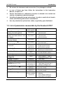

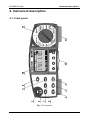
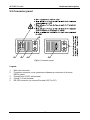
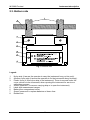
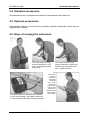
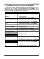
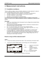

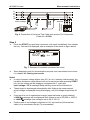
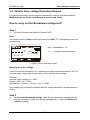

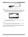


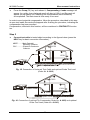
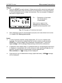
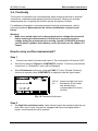
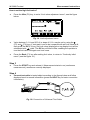
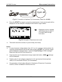
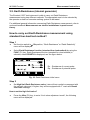
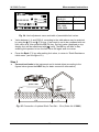
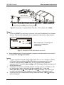
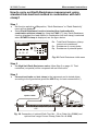
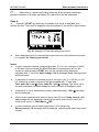
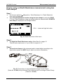
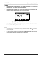


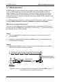

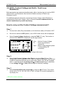

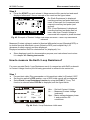

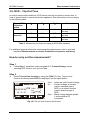

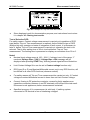
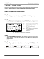
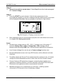
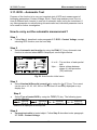
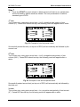


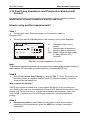
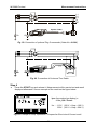

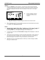

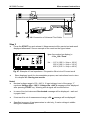
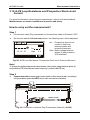
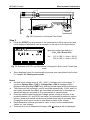
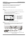

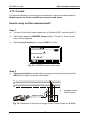
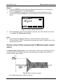
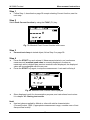
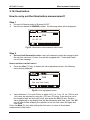
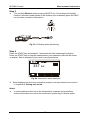
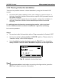
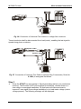


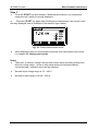
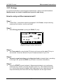
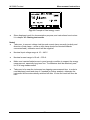
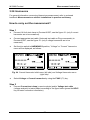
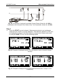
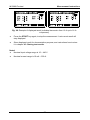
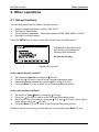
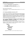


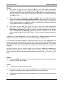
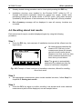
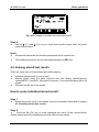

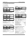
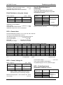


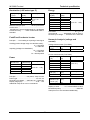
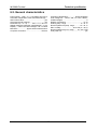


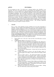


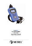
![Overview cPR67 and cPR84 [v00]](http://vs1.manualzilla.com/store/data/005648847_1-d158a5d3d4b92d14c7a3179652b88ffd-150x150.png)