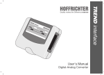
1
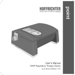
TREND interface User's Manual Digital-Analog Converter SERIAL NUMBER Every HOFFRICHTER GmbH device is supplied with a serial number for traceability purposes. Please enter your device‘s serial number here. You will find the serial number on the rating plate on the back of the device. Serial number: ..................................... Please always quote the serial number for all queries and complaints. CONFORMITY The device complies with the requirements of Directive 93/42/EEC. 2 Info CONTENTS Serial Number .............................................. 2 Conformity ................................................... 2 Symbols on the Rating Plate ........................ 4 Safety Information ........................................ 5 Intended Use ............................................... 6 Scope of Delivery ......................................... 6 Description of Device ................................... 7 Connections ............................................. 8 Indication of the LED ................................ 8 Output of SubD 15-pin connector ............. 9 Change of the voltage level ....................... 9 Cleaning and Disinfection ........................... 20 Safety Information ................................... 20 Device Surface ....................................... 20 Technical Data ........................................... 21 Disclaimer .................................................. 22 Contents 3 SYMBOLS ON THE RATING PLATE Observe the warning and safety instructions in the user‘s manual. CE conformity declaration Manufacturer Follow the user‘s manual. Do not dispose of the device in the household waste. Please contact the relevant customer services department to find out how to dispose of the device properly. 4 Symbols on the Rating Plate SAFETY INFORMATION Please read this user‘s manual through carefully before using your TREND interface for the first time. • The housing of the device does not provide any protection against ingress of water. • Never try to open the housing of TREND interface. • Never expose the device to rain, moisture or humidity. Malfunctions, damage and electric shocks can occure as a result. • Never place the TREND interface in the vicinity of other equipment or devices, such as defibrillators, diathermy equipment, mobile phones, microwave equipment, remote controlled toys, etc. Keep the manual in a safe place close to the device so that you can refer to it immediately if necessary. • If temperatures fall below - 5 °C or rise above + 50 °C, proper functioning of TREND interface may be impaired. The system must not be exposed to direct solar radiation. • Do not use the device if there is visible damage to it. Accidents, fires and electric shocks can occure as a result. • Make sure that no objects or fluids can penetrate into the device trough openings. This could lead to short circuits, damage, electric shocks and fires. Safety Information 5 INTENDED USE SCOPE OF DELIVERY TREND interface is intended for conversion of digital signals from the respiration therapy devices of HOFFRICHTER GmbH into analog signals and their transfer to polysomnography systems. Included in delivery: Additional the communication between the respiratory therapy device and a PC with evaluation software or a remote control shall be warranted. TREND interface is exclusively used in sleep laboratories by medical qualified personnel. 6 Intended Use and Scope of Delivery • TREND interface • Adaptor RS232/PC or TRENDremote • RS232 interface cable (connection between TREND interface and CPAPdevice) • Interface cable to the PSG-device e.g.: – Compumedics E-Serie – Embla S/N 7000 – Alice – Comlab 44 – Crystal – Sapphire / SleepScout Further on request. DESCRIPTION OF DEVICE To connect the TREND interface to a PSG device an interface cable is required. Then connect the PSG device to the TREND interface. The device converts the digital signals from the respiratory therapy device into analog signals for the PSG system. For this you first have to connect the TREND interface with the CPAP device. Use the interface cable. To show the data in the software of the PSG device, some adjustments in the PSG device may be necessary. Optional a remote control or a PC can be connected to the device. For this, use the delivered adaptor. CPAP device Patient TREND interface Remote control or PC PSG Description of Device 7 CONNECTIONS INDICATION OF THE LED The following connectors are available on the TREND interface: The LED indicates the following operation conditions: • RJ45 jack for connection with the respiratory therapy device (Port: CPAP) 1 Quick flashing Initialization phase On Device ready • SubD 15-Pin for connection with the PSG system (Interface: PSG) Flashing Error while running • RJ45 jack for connection with a remote control / PC (Port: PC) 1 Port: CPAP 1 8 galvanically isolated Description of Device Port: PC OUTPUT OF SUBD 15-PIN CONNECTOR PIN Signal 1 Ground 2 Channel 5 3 Channel 4 4 Channel 3 5 Channel 2 6 Channel 1 7 Channel 0 8 Ground 9 Ground 10 Amplification Channel 5 11 Amplification Channel 4 12 Amplification Channel 3 13 Amplification Channel 2 14 Amplification Channel 1 15 Amplification Channel 0 CHANGE OF THE VOLTAGE LEVEL The output voltage level of the channels zero to five is 0 V to 1 V. This level can be changed to 0 to 5 V by connecting ground and the accordant amplification channel. Interface PSG Description of Device 9 Signals from devices in the modes APAP and CPAP: AutoTREND (from V 1.5xx) Range 1 V Channel 0 10 Name Mask pressure Range (1 V) 0 V = 0 Pa 1 V = 5000 Pa Description Therapy pressure in the mask 1 Breathing flow 0 V = - 2.5 l/s 1 V = 2.5 l/s Breathing flow of the patient 2 Relative breathing volumen 0V = 0% 1 V = 100 % 3 Snoring 0 V = inactive 1 V = active Relative breathing volume is defined as breathing volume measured over 10 s, reductions in the signal are hypopnea or apnea Active, when snoring is detected 4 Airway constriction 0 V = inactive 1 V = active Active when raised airway constriction occurs 5 Internal signal 0 - 1023 Signal for the detailed internal evaluation Description of Device Signals from devices in the modes APAP and CPAP: AutoTREND (from V 1.5xx) Range 5 V Channel 0 Name Mask pressure Range (5 V) 0 V = 0 Pa 5 V = 5000 Pa Description Therapy pressure in the mask 1 Breathing flow 0 V = - 2.5 l/s 5 V = 2.5 l/s Breathing flow of the patient 2 Relative breathing volumen 0V = 0% 5 V = 100 % 3 Snoring 0 V = inactive 5 V = active Relative breathing volume is defined as breathing volume measured over 10 s, reductions in the signal are hypopnea or apnea Active, when snoring is detected 4 Airway constriction 0 V = inactive 5 V = active Active when raised airway constriction occurs 5 Internal signal 0 - 1023 Signal for the detailed internal evaluation Description of Device 11 Signals from devices in the modes APAP and CPAP: AutoTREND (from V 1.700), TRENDevent, TREND II AUTO, (i)CARAT et AUTO, VECTOR et / ET AUTO, VIVA II AUTO Range 1 V Channel 0 12 Name Mask pressure Range (1 V) 0 V = 0 Pa 1 V = 5000 Pa Description Therapy pressure in the mask 1 Breathing flow 0 V = - 2,5 l/s 1 V = 2.5 l/s Breathing flow of the patient 2 Relative breathing volumen 0V = 0% 1 V = 100 % 3 Snoring 0 V = inactive 1 V = active Relative breathing volume is defined as breathing volume measured over 10 s, reductions in the signal are hypopnea or apnea Active, when snoring is detected 4 Airway constriction 0 V = inactive 1 V = active Active when raised airway constriction occurs 5 Status APAP 0 V to 1 V 0 V = no status active 0.06 V = Adaptation phase 0.13 V = Leakage detected 0.25 V = Hyperventilation detected 0.50 V = Mouth expiration detected Description of Device Signals from devices in the modes APAP and CPAP: AutoTREND (from V 1.700), TRENDevent, TREND II AUTO, (i)CARAT et AUTO, VECTOR et / ET AUTO, VIVA II AUTO Range 5 V Channel 0 Name Mask pressure Range (5 V) 0 V = 0 Pa 5 V = 5000 Pa Description Therapy pressure in the mask 1 Breathing flow 0 V = - 2.5 l/s 5 V = 2.5 l/s Breathing flow of the patient 2 Relative breathing volumen 0V = 0% 5 V = 100 % 3 Snoring 0 V = inactive 5 V = active Relative breathing volume is defined as breathing volume measured over 10 s, reductions in the signal are hypopnea or apnea Active, when snoring is detected 4 Airway constriction 0 V = inactive 5 V = active Active when raised airway constriction occurs 5 Status APAP 0 V to 5 V 0 V = no status active 0.30 V = Adaptation phase 0.60 V = Leakage detected 1.25 V = Hyperventilation detected 2.50 V = Mouth expiration detected Description of Device 13 Signals from devices in the modes APAP and CPAP: TREND II AUTO, (i)CARAT et AUTO, VECTOR et / ET AUTO, VIVA II AUTO (each from V 2.120) Range 1 V Channel 0 14 Name Mask pressure Range (1 V) 0 V = 0 Pa 1 V = 5000 Pa Description Therapy pressure in the mask 1 Breathing flow 0 V = - 2,5 l/s 1 V = 2.5 l/s Breathing flow of the patient 2 Leakage flow 0 V = 0 ml/min 1 V = 5000 ml/s Display of leakage flow 3 Snoring 0 V = inactive 1 V = active Active, when snoring is detected 4 Airway constriction 0 V = inactive 1 V = active Active when raised airway constriction occurs 5 Status APAP 0 V to 1 V 0 V = no status active 0.06 V = Adaptation phase 0.13 V = Leakage detected 0.25 V = Hyperventilation detected 0.50 V = Mouth expiration detected Description of Device Signals from devices in the modes APAP and CPAP: TREND II AUTO, (i)CARAT et AUTO, VECTOR et / ET AUTO, VIVA II AUTO (each from V 2.120) Range 5 V Channel 0 Name Mask pressure Range (5 V) 0 V = 0 Pa 5 V = 5000 Pa Description Therapy pressure in the mask 1 Breathing flow 0 V = - 2.5 l/s 5 V = 2.5 l/s Breathing flow of the patient 2 Leckage-Flow 0 V = 0 ml/min 5 V = 5000 ml/s Display of leakage flow 3 Snoring 0 V = inactive 5 V = active Active, when snoring is detected 4 Airway constriction 0 V = inactive 5 V = active Active when raised airway constriction occurs 5 Status APAP 0 V to 5 V 0 V = no status active 0.30 V = Adaptation phase 0.60 V = Leakage detected 1.25 V = Hyperventilation detected 2.50 V = Mouth expiration detected Description of Device 15 Signals from devices in the mode FLEXLINE: AutoTREND (from V. 1.700), TRENDevent, TREND II AUTO, (i)CARAT et AUTO, VECTOR et / ET AUTO, VIVA II AUTO Signals from devices in the modes FLEXLINE and CPAP: TREND 210, TREND II CPAP, VECTOR et / ET CPAP, VIVA II CPAP Range 1 V Channel 0 16 Name Mask pressure Range (1 V) 0 V = 0 Pa 1 V = 5000 Pa Description Therapy pressure in the mask 1 Breathing flow 0 V = - 2.5 l/s 1 V = 2.5 l/s Breathing flow of the patient 2 Leakage flow 0 V = 0 ml/min 1 V = 5000 ml/s Display of leakage flow 3 4 Not used Status FLEXLINE Leakage detected 0 V = inactive 0.5 V = active Active, when leakage is detected 5 Status FLEXLINE Basic pressure Hyperventilation detected 0 V to 1 V 0 V = no status active 0.25 V = Basic pressure 0.50 V = Hyperventilation detected Description of Device Signals from devices in the mode FLEXLINE: AutoTREND (from V. 1.700), TRENDevent, TREND II AUTO, (i)CARAT et AUTO, VECTOR et / ET AUTO, VIVA II AUTO Signals from devices in the modes FLEXLINE and CPAP: TREND 210, TREND II CPAP, VECTOR et / ET CPAP, VIVA II CPAP Range 5 V Channel 0 Name Mask pressure Range (5 V) 0 V = 0 Pa 5 V = 5000 Pa Description Therapy pressure in the mask 1 Breathing flow 0 V = - 2.5 l/s 5 V = 2.5 l/s Breathing flow of the patient 2 Leckage-Flow 0 V = 0 ml/min 5 V = 5000 ml/s Display of leakage flow 3 4 Not used Status FLEXLINE Leakage detected 0 V = inactive 2.5 V = active Active, when leakage is detected 5 Status FLEXLINE Basic pressure Hyperventilation detected 0 V to 5 V 0 V = no status active 1.25 V = Basic pressure 2.50 V = Hyperventilation detected Description of Device 17 Signals from devices in all modes: TREND II BILEVEL, TREND II BILEVEL ST20, TREND II BILEVEL ST30, VECTOR et / ET BILEVEL, VECTOR et / ET BILEVEL ST20, VECTOR et BILEVEL ST30, (i)CARAT et BILEVEL, (i)CARAT et BILEVEL ST20, iCARAT et BILEVEL ST30, PRISMA II, MELODY II, MELODY II ST30 Range 1 V Channel 0 18 Name Mask pressure Range (1 V) 0 V = 0 Pa 1 V = 5000 Pa Description Therapy pressure in the mask 1 Breathing flow 0 V = - 2.5 l/s 1 V = 2.5 l/s Breathing flow of the patient 2 Leakage flow 0 V = 0 ml/min 1 V = 5000 ml/s Display of leakage flow 3 Not used 4 Not used 5 Not used Description of Device Signals from devices in all modes: TREND II BILEVEL, TREND II BILEVEL ST20, TREND II BILEVEL ST30, VECTOR et / ET BILEVEL, VECTOR et / ET BILEVEL ST20, VECTOR et BILEVEL ST30, (i)CARAT et BILEVEL, (i)CARAT et BILEVEL ST20, iCARAT et BILEVEL ST30, PRISMA II, MELODY II, MELODY II ST30 Range 5 V Channel 0 Name Mask pressure Range (5 V) 0 V = 0 Pa 5 V = 5000 Pa Description Therapy pressure in the mask 1 Breathing flow 0 V = - 2.5 l/s 5 V = 2.5 l/s Breathing flow of the patient 2 Leakage flow 0 V = 0 ml/min 5 V = 5000 ml/s Display of leakage flow 3 Not used 4 Not used 5 Not used Description of Device 19 Signals from point Range 1 V Channel 0 20 Name Mask pressure 1 Not used 2 Not used 3 Not used 4 Not used 5 Not used Description of Device Range (1 V) 0 V = 0 Pa 1 V = 5000 Pa Description Therapy pressure in the mask Signals from point Range 5 V Channel 0 Name Mask pressure 1 Not used 2 Not used 3 Not used 4 Not used 5 Not used Range (5 V) 0 V = 0 Pa 5 V = 5000 Pa Description Therapy pressure in the mask Description of Device 21 Signals from point 2 Range 1 V Channel 0 22 Name Mask pressure Range (1 V) 0 V = 0 Pa 1 V = 5000 Pa Description Therapy pressure in the mask 1 Breathing flow 0 V = - 2.5 l/s 1 V = 2.5 l/s Breathing flow of the patient 2 Leakage flow 0 V = 0 ml/min 1 V = 5 l/s Display of leakage flow 3 Snoring 0 V = inactive 1 V = active Active, when snoring is detected 4 Airway constriction 0 V = inactive 1 V = active 5 Internal signal Active when raised airway constriction occurs (incl. flattening) Signal for the detailed internal evaluation Description of Device 0 V = no status active 0.063 V = Adaptation phase 0.125 V = Leakage detected 0.25 V = Hyperventilation detected 0.50 V = Basic pressure detected Signals from point 2 Range 5 V Channel 0 Name Mask pressure Range (5 V) 0 V = 0 Pa 5 V = 5000 Pa Description Therapy pressure in the mask 1 Breathing flow 0 V = - 2.5 l/s 5 V = 2.5 l/s Breathing flow of the patient 2 Leakage flow 0 V = 0 ml/min 5 V = 5 l/s Display of leakage flow 3 Snoring 0 V = inactive 5 V = active Active, when snoring is detected 4 Airway constriction 0 V = inactive 5 V = active 5 Internal signal Active when raised airway constriction occurs (incl. flattening) Signal for the detailed internal evaluation 0 V = no status active 0.313 V = Adaptation phase 0.625 V = Leakage detected 1.25 V = Hyperventilation detected 2.50 V = Basic pressure detected Description of Device 23 CLEANING AND DISINFECTION SAFETY INFORMATION • Do not use any volatile substances, such as solvents, to aviod damaging of the surface. Clean the device only using a soft, dry cloth. • Do not immerse the device in water or solvent. • Make sure that no water or other fluids can penetrate into the device trough opening or venting slots. This could lead to short circuits, damage, electric shocks and fires. 24 Cleaning and Disinfection DEVICE SURFACE Use a cloth moistened with soap water to clean the external surfaces of the device. Then wipe the device with clear water to remove residual cleaning agent. The devices surfaces should be disinfected at regular intervals and in case of suspected contamination. We recommend Mikrozid® Liquid for disinfecting the external surfaces of the device. Disinfectants which are recognized according to the RKI Guideline can also be used. Before being put into operation, the device should be completely dry. TECHNICAL DATA Specifications and Performance Dimensions (W x H x D): 115 x 84 x 25 mm Weight: 110 g Operating conditions Operating temperature: 0 °C to + 40 °C Relative humidity: 10 % to 95 % Air pressure: 700 to 1060 hPa Storage conditions: - 10 °C to + 50 °C (Store in a dry, vibration free position; store device and accessories in their original packing) Standards The system complies with the following standards and guidelines: • • • • • • • EC directive 93/42/EEC DIN EN ISO 14971:2000 DIN EN ISO 14971:A1 2003 IEC / TR 6051 UL 1577 Component Recognition Program: 2500 V rms Isolationsspannung DIN EN 60747-5-2; VDE 0884-2:2003-01 DIN EN 60950; VDE 0805:2001-12 The manufacturer reserves the right to make technical changes without notice. Technical Data 25 DISCLAIMER HOFFRICHTER GmbH is not liable for consequences in terms of safety, reliability and performance of the product where: • interventions, modifi cations, extensions, calibration, repairs and maintenance are carried out by persons not authorized by us, • other manufacturers’ accessories and spare parts are used that have not been approved by us for use on the product, • the product is used other than as described in the user’s manual or • the hygiene and cleaning instructions described in the user’s manual have not been complied with. Statutory guarantee rights remain unaffected by this. 26 Disclaimer NOTES .................................................................................................................................................. .................................................................................................................................................. .................................................................................................................................................. .................................................................................................................................................. .................................................................................................................................................. .................................................................................................................................................. .................................................................................................................................................. .................................................................................................................................................. .................................................................................................................................................. .................................................................................................................................................. Notes 27 HOFFRICHTER GmbH Mettenheimer Straße 12 / 14 19061 Schwerin Germany Phone: +49 385 39925 - 0 Fax: +49 385 39925 - 25 E-Mail: [email protected] www.hoffrichter.de TRENDinterface ENG_2012-08-17_08 Art. no.: 0000 5805