1
FLEXALARM 620
CONVENTIONAL
FIRE ALARM CONTROL PANEL
Installation & Operation Manual
The Gamewell Company
60 Pleasant Street
Ashland, MA 01721
UL, FM, CSFM, MEA Listed
Technical Manuals Online! - http://www.tech-man.com
P/N 71217
Revision 5
11-22-01
This page intentionally blank
Technical Manuals Online! - http://www.tech-man.com
PROPRIETARY MATERIAL
The information contained in this manual is proprietary to The Gamewell Company. Such information
and technical drawings may not be copied or reproduced in any manner, or disclosed to organizations
that might be competitive to Gamewell, without the express prior written consent of The Gamewell
Company.
Technical Manuals Online! - http://www.tech-man.com
This page intentionally blank
Technical Manuals Online! - http://www.tech-man.com
GENERAL INFORMATION
The Gamewell Company thanks you for choosing the FLEXALARM 620 Conventional Control Panel to
serve your monitor and control signaling needs. As with all our products we have taken great care to insure
that we have provided a quality alarm control panel. To receive maximum benefit and many years of
reliable service we would like to make the following recommendations:
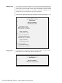
1.
Read this manual carefully and in it's entirety before proceeding with the installation of the Flex 620
Control Panel.
2.
Never make any connections or perform any system programming with the power connected.
3.
Gamewell spends many hours testing devices that are supplied by Gamewell to be used with it's control
panels to verify compatibility. To maximize system performance, and minimize risk of damage to the
equipment, we suggest using all Gamewell Components.
4.
There is no substitute for proper maintenance and testing of this or any Life Safety product. Gamewell
recommends testing and maintenance of your FLEX 620 system in accordance with the guidelines set
forth by the National Fire Protection Association, be done on a regular basis, as a minimum.
5.
This manual should be stored with the FLEX 620 Control Panel for future reference, and should not be
removed.
Thank you again for choosing Gamewell. If you have any comments regarding your FLEX 620 Conventional
Control Panel, or other Gamewell products, please feel free to write us at:
The Gamewell Company
Product Marketing Department
60 Pleasant Street
Ashland, MA 01721
Phone:
Fax:
(508) 231-1400
(508) 231-0900
Technical Manuals Online! - http://www.tech-man.com
This page intentionally blank
Technical Manuals Online! - http://www.tech-man.com
Technical Manuals Online! - http://www.tech-man.com
This page intentionally blank
Technical Manuals Online! - http://www.tech-man.com
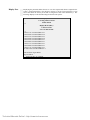
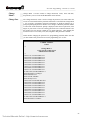
TABLE OF CONTENTS
SYSTEM OVERVIEW ..................................................................................................................................................... 2
FLEX 620 Control Panel ..................................................................................................................................... 3
Modular Construction.......................................................................................................................................... 3
Common Control Module.................................................................................................................................... 4
SYSTEM I/O COMPONENTS (600 SERIES).................................................................................................................... 6
Initiating Module ................................................................................................................................................. 6
Indicating Module................................................................................................................................................ 6
600 Series Modules ............................................................................................................................................. 7
SYSTEM OPERATION ............................................................................................................................................... 9
COMMON CONTROL DISPLAY - FUNCTIONAL DESCRIPTION ................................................................................... 10
CONTROLS ...................................................................................................................................................... 10
INDICATORS ................................................................................................................................................... 11
Standard Operating Display - (Legend Key Designators).................................................................................. 12
Module Displays................................................................................................................................................ 13
SYSTEM OPERATING CHARACTERISTICS .................................................................................................................. 14
Overview ........................................................................................................................................................... 14
Alarm Verification............................................................................................................................................. 15
And Initiating Circuit......................................................................................................................................... 16
SYSTEM OPERATING CONDITIONS ............................................................................................................................ 17
Default Mode..................................................................................................................................................... 17
Normal Quiescent Condition ............................................................................................................................. 17
(default) ............................................................................................................................................................. 17
Alarm Condition (default) ................................................................................................................................. 18
OPERATING PROCEDURES ......................................................................................................................................... 19
INSTALLATION........................................................................................................................................................ 24
Flex 620 System Housing .................................................................................................................................. 25
Hardware Assembly........................................................................................................................................... 26
Module Identification and Placement ................................................................................................................ 28
Main Power Supply ........................................................................................................................................... 30
Specifications..................................................................................................................................................... 30
Interconnects...................................................................................................................................................... 30
Auxiliary Power Supply..................................................................................................................................... 31
Interconnects...................................................................................................................................................... 31
Common Control Specifications........................................................................................................................ 32
Bus Driver Module ............................................................................................................................................ 35
CPU Module...................................................................................................................................................... 36
SYSTEM I/O COMPONENTS (600 SERIES).................................................................................................................. 38
Conventional Input Module .............................................................................................................................. 38
Conventional Input Module Terminal Description ............................................................................................ 39
Class "A" Adapter -Conventional Input Module - Terminal Description .......................................................... 39
Universal Signal Circuit Module ....................................................................................................................... 40
Universal Signal Circuit Module Terminal Description .................................................................................... 41
Class "A" Adapter - Universal Signal Module - Terminal Description ............................................................. 41
Technical Manuals Online! - http://www.tech-man.com
Relay Module .................................................................................................................................................... 42
Relay Module ................................................................................................................................................... 43
Relay Expansion Module................................................................................................................................... 43
Building Control Module................................................................................................................................... 44
Building Control Module................................................................................................................................... 45
City Tie Extender Module ................................................................................................................................. 46
Initial System Startup......................................................................................................................................... 47
FLEX 600 CONTROL PANEL......................................................................................................................... 48
COMPATIBLE SMOKE DETECTORS & BASES ......................................................................................... 48
FLEX 600 CONTROL PANEL......................................................................................................................... 48
COMPATIBLE AUXILIARY DEVICES ......................................................................................................... 48
FLEX 600 CONTROL PANEL......................................................................................................................... 48
COMPATIBLE INITIATING DEVICES FOR “AND“ ZONES...................................................................... 48
FLEX 600 .......................................................................................................................................................... 49
COMPATIBLE INDICATING APPLIANCES ................................................................................................ 49
FLEX 600 .......................................................................................................................................................... 50
COMPATIBLE INDICATING APPLIANCES (Cont.) .................................................................................... 50
PROGRAMMING ...................................................................................................................................................... 53
PROGRAMMING OVERVIEW - FLEXALARM 620 ...................................................................................................... 54
Programming Options........................................................................................................................................ 55
Control By Event ............................................................................................................................................... 59
Access Levels .................................................................................................................................................... 60
Figure 4.1 Common Control Display - Operating Mode ................................................................................. 60
Password Entry .................................................................................................................................................. 60
Input Circuit - Programming.............................................................................................................................. 63
Output Circuit - Programming ........................................................................................................................... 64
Restoring Output Circuits .................................................................................................................................. 65
Programming Signal Circuit Special Functions ................................................................................................. 66
Control-By-Event - Programming...................................................................................................................... 67
COMPUTER/LAPTOP PROGRAMMING OVERVIEW .................................................................................................... 68
Overviewof Computer Programming................................................................................................................. 68
Interconnect ....................................................................................................................................................... 68
Communication Protocol ................................................................................................................................... 68
PROCOMM SOFTWARE ............................................................................................................................................... 68
Configuration..................................................................................................................................................... 68
Line Settings ..................................................................................................................................................... 68
Setup Menu........................................................................................................................................................ 68
Terminal Setup ................................................................................................................................................. 69
General Setup ................................................................................................................................................... 69
ASCII Transfer ................................................................................................................................................. 70
SYSTEM MONITORING & CONTROL.......................................................................................................................... 70
Status Monitoring .............................................................................................................................................. 70
Access Levels .................................................................................................................................................... 70
Control Strings................................................................................................................................................... 70
SYSTEM PROGRAMMING VIA COMPUTER ................................................................................................................. 71
System Menu ..................................................................................................................................................... 71
Display Menu .................................................................................................................................................... 71
Config Menu..................................................................................................................................................... 71
Display Config................................................................................................................................................... 72
Technical Manuals Online! - http://www.tech-man.com
System Configuration ........................................................................................................................................ 73
Codes Defined ................................................................................................................................................... 73
Modular Placement............................................................................................................................................ 73
Card Locations................................................................................................................................................... 73
0 through 7......................................................................................................................................................... 73
Cards # 8 - 39 .................................................................................................................................................... 73
Module Bus ....................................................................................................................................................... 73
Card ID # ........................................................................................................................................................... 73
Download Config.............................................................................................................................................. 75
Display Dict. Menu............................................................................................................................................ 75
Display Dict....................................................................................................................................................... 76
Download Dict................................................................................................................................................... 76
Display Events ................................................................................................................................................... 77
Display, Misc..................................................................................................................................................... 77
Display Pass....................................................................................................................................................... 78
Display Codes.................................................................................................................................................... 79
Display Ver........................................................................................................................................................ 80
Display Zone...................................................................................................................................................... 80
Change Menu..................................................................................................................................................... 81
Change Config ................................................................................................................................................... 81
Change Dictionary ............................................................................................................................................. 81
Change Dict.Words ........................................................................................................................................... 82
Upload Dictionary ............................................................................................................................................. 82
Dictionary File................................................................................................................................................... 83
Change Card ...................................................................................................................................................... 84
Change Misc ...................................................................................................................................................... 84
Change Menu 1.................................................................................................................................................. 85
Change Pass....................................................................................................................................................... 85
Change Code...................................................................................................................................................... 86
Change Date ...................................................................................................................................................... 87
Change Seq ........................................................................................................................................................ 87
Change Baud...................................................................................................................................................... 88
Baud Rate Switch Settings................................................................................................................................. 88
Change Words ................................................................................................................................................... 89
Change Menu 2.................................................................................................................................................. 91
Change City ....................................................................................................................................................... 91
Change Sig Sil ................................................................................................................................................... 91
Change Ann ....................................................................................................................................................... 91
Change Trbl ....................................................................................................................................................... 92
Change Dialer .................................................................................................................................................... 92
Change Prefix .................................................................................................................................................... 92
Test Menu.......................................................................................................................................................... 93
Test Input........................................................................................................................................................... 93
Test Output ........................................................................................................................................................ 94
Test ID............................................................................................................................................................... 94
Test Gnd ............................................................................................................................................................ 95
Test Lamp .......................................................................................................................................................... 95
IDENTIFLEX 620 BATTERY CALCULATION CHART ............................................................................. 96
Technical Manuals Online! - http://www.tech-man.com
Technical Manuals Online! - http://www.tech-man.com
This page intentionally blank
Technical Manuals Online! - http://www.tech-man.com
Flex 620 System Description - Revision 5, 11/22/01
Section 1
FLEXALARM 620
System Description
System Overview
2
Technical Manuals Online! - http://www.tech-man.com
Flex 620 System Description - Revision 5, 11/22/01
FLEX 620
Control Panel
The Gamewell FlexAlarm 620 Conventional Alarm Control Panel is a limited energy
fire, supervisory, alarm system consisting of a cabinet, I/O circuits, power supplies,
and front panel displays. The Flex 620 is expandable to monitor, control and display
up to 128 input/output circuits. It is available in two cabinet sizes, four bay and eight
bay. The four bay cabinet (F624) will accommodate 4 of the 620 series modules in
addition to the common control, power supply and batteries. The eight bay cabinet
(F628) will accommodate 8 of the 620 series modules in addition to the common
control, power supply and batteries.
The design of the system utilizes a modular building block approach. Through
selection of individual I/O modules (i.e. initiating, indicating and relay control
modules, etc.) the user can customize the control panel for specific applications.
The Flex 620 control panel utilizes a unique initialization programming process,
SmartStart.
This initialization process stores the project specific system
configuration in memory. Then a control-by-event table is automatically created that
allows any system input to activate the system outputs. Upon completion of the
initialization process the system is completely operable in a general alarm situation
with the control-by-event data tables protected in non-volatile memory.
___________________________________________________________________________________________
Modular
Construction
The Flex 620 modular control panel consists of the common control section,
conventional input module(s), universal signal module(s), relay module(s), building
control module(s), city tie module(s), and power supplies. Other devices that can be
used in conjunction with the Flex 620 system include the remote annunciators, printer
interfaces and alphanumeric displays. These devices operate by means of the serial
communications port which is isolated via an optional communications isolator
module.
The cabinet utilizes dead front construction in either a four or eight bay arrangement.
The modules will conform to numerous system configurations that accommodate
simple and complex systems.
____________________________________________________________________________________________
3
Technical Manuals Online! - http://www.tech-man.com
Flex 620 System Description - Revision 5, 11/22/01
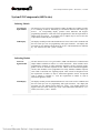
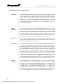
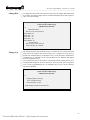
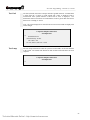
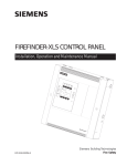
Common
Control Module
The common control module (CCM) or section consists of four modules; the common
control display, the bus driver module, a relay expansion module, and the main CPU
module.
Common
Control
Display
The Common Control Display (CCD) is divided into two sections, the left and right
displays. It provides the user with visual indicators (LED's) for status indication and
guided prompts. The sixteen tactile switches are used to operate the system as well as
enter data during system programming. All alarm, fault, supervisory and security
status changes are annunciated by means of LED indication and the user is prompted
with the proper sequence of operation. The "Power On" LED indicator is green,
alarms or activated signal and city tie circuits are indicated by red LED's and faults are
indicated by yellow LED's.
CPU Module
The CPU module (or micro processor module) contains the system operating firmware
and non-volatile memory. It provides all the processing functions and system memory
as well as providing the local/remote communications interface.
Relay
Expansion
Module
The Relay Expansion Module (REM) provides 4 common relay circuits. When
connected to the bus driver module this module provides Common Alarm, Common
Trouble and Supervisory Form C relay contacts. Each relay has a fused common rated
at ten (10) amps. The expansion module mounts (via standoffs) to the right side of the
bus driver module.
Bus
Driver
Module
The Bus Driver Module (BDM) contains the circuitry that interfaces with the CPU
module and the system modules. The bus driver module is equipped with two Style Y
or Z, limited energy signaling circuits, a ground fault detection circuit and a city tie
circuit. It has three power limited outputs, 24 Vdc auxiliary power, 12 Vdc, and
resetable 24 Vdc smoke detector power. Circuitry to monitor the status of the CPU
and set the system in a default mode of operation is also incorporated in the bus driver
module.
___________________________________________________________________________________________
Common Control
Display
Bus Driver
Module
Relay Expansion
Module
CPU Module
620 Common Control Module
4
Technical Manuals Online! - http://www.tech-man.com
Flex 620 System Description - Revision 5, 11/22/01
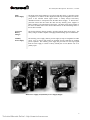
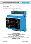
Main
Power Supply
The main power supply (MPS-8) is an eight (8) amp DC supply. It provides 4 amps
of regulated 5, 12, and 24 volt DC outputs and four amps of unregulated 24 volt DC
power to the common control signal circuits. A battery charger and battery
distribution block are incorporated into the Main Power Supply. A "Brown Out"
protection circuit that will switch the main and any auxiliary power supplies to
battery standby is also integrated into the supply. The main power supply mounts in
the lower left hand corner of the cabinet and connects via interconnecting cables to
the bus driver module.
Lead Acid
Battery
Charger
The lead acid battery charger module is provided with the main power supply. The
battery charger module is capable of charging and maintaining up to 60 AH batteries.
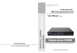
Auxiliary
Power Supply
The auxiliary power supply (APS-8) provides eight (8) amps of unregulated 24 VDC
power. Two (2), four (4) amp circuits are available from its connectors for signaling
power expansion. The auxiliary power supply has provisions for receiving a signal
from the main supply to switch to battery standby due to low (Brown out) or no
primary input.
Main Power Supply (Left)Auxiliary Power Supply (Right)
5
Technical Manuals Online! - http://www.tech-man.com
Flex 620 System Description - Revision 5, 11/22/01
System I/O Components (600 Series)
___________________________________________________________________________________________
Initiating Module
Conventional
Input Module
The 600 series Conventional Input Modules (CIM-4 & CIM-8) are available in either
4 or 8 initiating circuits for monitoring of conventional detectors and contact type
devices.
Its corresponding display provides status indication and Bypass/
programming capabilities. Each zone can be programmed to meet the requirements of
NFPA Styles B (Class B). An optional Class A adapter may be used to meet the
requirements of NFPA Style D if required.
CIM Display
The display module provides LED annunciation of Alarm and Trouble conditions and
has one switch per zone for programming and bypass functions. The display has
provisions for user defined custom labels per circuit. LED annunciation is indicated
by - red - Alarm (active) and - yellow - Trouble.
___________________________________________________________________________________________
Indicating Module
Universal
Signal Module
The Flex 600 series universal signal modules (USM-4 & USM-8) are a multi-function
output modules available in either 4 or 8 circuit increments. These modules can be
programmed to function as either notification appliance circuits, releasing circuits,
speaker circuits or fireman's telephone circuits. When used as notification appliance
circuits, these modules can be programmed for steady, 60PPM, 120PPM, temporal,
zone coded or California UFC signaling outputs. These circuits are designed to meet
the requirements of NFPA 72, Style Y notification appliance circuits. An optional
Class A adapter is available to meet the requirements of NFPA 72, Style Z
notification appliance circuits.
USM Display
The display module provides LED annunciation of Alarm and Trouble conditions and
has one switch per zone for programming and bypass functions. The display has
provisions for user defined custom labels per circuit. The module displays are
supplied with user tactile switches per circuit. LED annunciation indication is - red Alarm (active) and - yellow - Trouble.
___________________________________________________________________________________________
6
Technical Manuals Online! - http://www.tech-man.com
Flex 620 System Description - Revision 5, 11/22/01
600 Series Modules
Relay Modules
The 600 series relay modules (RM-4 and RM-8) have been designed to supply 4 or 8
Form C relays for control of auxiliary functions. The relays are controlled by the
main CPU and are fully field programmable. A feedback point for positive
confirmation of activation has been supplied with each set of contacts. The relays are
rated at 10 amps with a fused common to protect the internal circuitry.
The relay module display is provided with green (inactive) and red (active) LED's.
The tactile switches (per relay point) can be used to program, bypass or test the relay
circuits.
___________________________________________________________________________________________
Relay Display
Building
Control
Module
The 600 series building control modules, (BC-4 & BC-8) along with their
On/Off/Auto switch display, are designed to provide an interface between the control
panel and HVAC systems. The building control module is available in 4 or 8 circuit
modules that are monitored and controlled by the MPU bus. Their relays are rated at
10 Amps with supervised feedback points for positive confirmation of the
programmed action. Each Form A/B relay pair is programmable independently and
fused on the relay common to protect the internal circuitry.
The building control module display provides LED annunciation (green - inactive,
and red - active) indicating relay state or feedback. The display comes with tactile
switches per circuit and a three position On/Off/Auto switch for manual override.
___________________________________________________________________________________________
BCM Display
City Tie
Module
The 600 series City Tie Module and its associated display provide 4 additional,
limited energy, polarity reversal/city tie circuits to a system. Each circuit has
independently programmable operation.
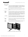
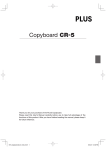
Module
Displays
The city tie module displays are supplied with red Alarm (active) and yellow Trouble
LED's with user tactile switches for programming, bypass and test per circuit.
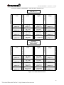
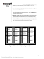
Representative Inner Cabinet Module Assembly (USM, CIM, RM)
7
Technical Manuals Online! - http://www.tech-man.com
Technical Manuals Online! - http://www.tech-man.com
Section 2
FLEXALARM 620
System Operation
Technical Manuals Online! - http://www.tech-man.com
Flex 620 System Operation - Revision 5, 11/22/01
_______________________________________________________________________________________________
Common Control Display - Functional Description
CONTROLS
Acknowledge Switch
The Acknowledge tactile switch (ACK), silences the internal buzzer of the
panel. Any signal circuit, building control or relay programmed to return to the
normal condition, when the "ACK" switch is depressed, will return to normal.
Should a second alarm occur, the circuits which had returned to normal will reactivate.
∆ WARNING !
Do not RESET the system until the Authority having
Jurisdiction has authorized reset.
Reset Switch
The Reset tactile switch (RESET) removes power from the initiating circuits for
a period of four (4) seconds. Power is temporarily removed from the S+ Sterminals, any devices latched into alarm should return to the normal condition
(provided the cause of alarm has been eliminated). The signal circuits, city tie,
alarm relay and/or supervisory relay will restore and the panel will return to the
normal quiescent condition.
Signal Silence
The Signal Silence tactile switch (SIGNAL SILENCE ) will silence (i.e. return
to normal), any signal circuit, building control point or relay that is
programmed to restore on signal silence. The signal silence switch is
alternating action switch. Pressing the signal silence switch will return the
silenced circuits to an active state.
Drill
The Drill tactile switch (DRILL) will activate all circuits that have been
programmed to sound when the Drill switch is pressed. The Drill switch is
alternate acting, pressing the Drill switch again will deactivate the test.
∆ WARNING !
All circuits selected for WALKTEST become disable and
will not Alarm the system should a real emergency occur.
WalkTest
The Walktest tactile switch (WALKTEST) will provide a means for one man to
test the devices in the system both silently and audibly. Walktest can only be
completed in the security access level 3 mode. The access of the Walktest
function is activated by depressing the Walktest switch and depressing the
"Enter" key. Any circuits may be selected for WalkTest. When the user has
completed selecting the circuits (Initiation or Indicating i.e. signal), depress the
"Enter" key. If indicating signals were selected, these circuits will annunciate
the alarm and troubles created on the initiation circuits. Should the circuit be
placed in alarm, the signals will sound 2 short signals. Should the circuit be
placed in trouble, the signals will sound 1 short signal. Should no signals be
selected, the test will be silent. When an actual alarm occurs on a circuit not
selected for WalkTest circuits, the system will go into full alarm sequence.
10
Technical Manuals Online! - http://www.tech-man.com
Flex 620 System Operation - Revision 5, 11/22/01
_______________________________________________________________________________________________
Bypass
The Bypass tactile switch is used to disconnect a circuit that is damaged and
cannot be cleared. Bypassing a circuit should only be a temporary solution to a
problem and not a long term solution. Your service company should be advised
immediately so full system operation may continue as soon as possible. When
the Bypass switch is depressed it will illuminate the bypassed circuits LED's.
The bypass switch is an alternating action switch. Depressing the switch again
will enable the bypassed circuit. Press "Enter" at the completion of the Bypass
actions.
Enter
The "Enter" tactile key is used to request password access or system
programming and enter data while in the programming mode. It also provides
the means to access system functions during WalkTest and bypass operations.
___________________________________________________________________________________________
INDICATORS
POWER ON
The green "Power On" LED indicates AC line operation. When pulsing, this
indicates a problem with the incoming AC line voltage, main or backup power
supplies.
BATTERY FAULT
The yellow "Battery Fault" LED indicates a problem with the battery, or battery
connections.
COMMON ALARM
The common "Alarm" LED (red) indicates a common fire alarm has been
activated in the system.
PRE-ALARM
The common "PreAlarm" LED (red) indicates the system in a first stage alarm
process.
ANNUNCIATOR
FAULT
The yellow "Annunciator" LED indicates a problem with a remote annunciator.
WALKTEST
The yellow "WalkTest" LED indicates that part of the system is in the WalkTest
mode. All zones that flash at the same rate as the WalkTest LED are in the
WalkTest mode.
EARTH FAULT
The yellow "Earth Fault" LED indicates that the system's wiring is not adequately
isolated from earth ground.
DRILL
The Drill LED (yellow) indicates the Drill feature has been activated.
ACKNOWLEDGE
The Acknowledge LED's (yellow) illuminate to indicate the next action is to
press the "ACK" switch.
SUPERVISORY
ALARM
The common Supervisory LED (yellow) indicates a supervisory zone has
activated (alarmed).
BYPASS / ENABLE
The yellow "Bypass/Enable" LED indicates that part of the system is bypassed.
All points that flash at the same rate as the bypass/enable LED are bypassed.
11
Technical Manuals Online! - http://www.tech-man.com
Flex 620 System Operation - Revision 5, 11/22/01
_______________________________________________________________________________________________
(Indicators - continued)
CITY TIE
The City Tie LED's are red for alarm, flashing yellow for trouble and steady
yellow to indicate transmission of trouble conditions.
SIGNAL CIRCUIT 1
The "Signal CIR 1" LED's are red for alarmed, yellow for trouble.
SIGNAL CIRCUIT 2
The "Signal CIR 2" LED's are red for alarmed, yellow for trouble.
RESET
The "Reset" LED (yellow) flashes when the reset switch is available for use.
TROUBLE
The "Trouble" LED (yellow) indicates the system is not in the normal
condition, or a fault is detected.
TROUBLE/SIL
The yellow "Trouble/Sil" LED indicates that the system trouble has been
acknowledged.
SIGNAL SILENCE
The yellow "Signal Silence" LED indicates the audible signals connected to
the system are not sounding.
SIGNAL
SILENCE
SOUNDING
The yellow "Signal Silence" LED indicates the audible signals connected to
the system are sounding.
PASSWORD
REQUIRED
The yellow "Password Required" LED indicates that the user must enter a
password for further action.
PASSWORD
ACCEPTED
The yellow "Password Accepted" indicates the password was accepted.
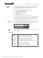
Standard Operating Display - (Legend Key Designators)
POWER ON
PRE-ALARM
ANNUN. FAULT
EARTH FAULT
FIRE
BATTERY FAULT
COMMON ALARM
WALKTEST
DRILL
1
SUPERVISORY
BYPASS/
ENABLE
ACKNOWLEDGE
5
ALARM
CITY TIE
SECURITY
TROUBLE
6
2
RESET
COMMON TRBL.
ALARM
TROUBLE
SIG CKT
TRBL. SILENCED
TROUBLE
3
PASSWORD REQD.
SIGNAL
SILENCE
ENTER
SIG CKT
PASSWORD ACCEPT
TROUBLE
4
Figure P-1, Standard Operating Legend
12
Technical Manuals Online! - http://www.tech-man.com
7
ALARM
8
Flex 620 System Operation - Revision 5, 11/22/01
_______________________________________________________________________________________________
Module Displays
Alarm Display
(Standard)
The alarm display is a multi-purpose display module. The display module provides
LED annunciation of alarm conditions for input circuits, signal circuits, and the city tie.
The display layout is as follows; circuits 1 through 4 are fixed on the left side of the
display (top to bottom). Circuits 5 through 8 are fixed on the right side of the display
(top to bottom). The display is complete with eight tactile switches, eight red LED's
and eight yellow LED's. The eight "point" tactile switches, governing individual
circuits, are used for programming, bypassing, and WalkTest (only zone and signal
circuits can utilize the WalkTest function).
The red LED indicates the circuit is;
! alarm/alarmed,
! activate/enabled.
The yellow LED (on steady) indicates;
! trouble/fault,
! off normal indication
! or service is required
! problem exists
! check for open
! short or ground
Relay Module
Display
The relay module display is used as a display module. The display is configured with
relays 1 through 4 are fixed on the left side of the display (top to bottom). Relays 5
through 8 are fixed on the right side of the display (top to bottom). The display is
complete with eight tactile switches, eight red LED's and eight green LED's. The eight
"point" tactile switches, governing individual circuits, are used for programming and
bypassing the selected circuit.
The red LED (on steady) indicates;
! alarm/alarmed,
! activate/enabled
The green LED indicates;
! normal
! not energized
! feedback point normal
In the programming mode, the green LED (on steady) indicates the relay is selected. If
the green LED is flashing indicates the relay is bypassed.
Building
Control
Display
The building control display is used as a control display module. Rotary switches
provide for manual control of the relays. The switch is a three position
ON/OFF/AUTO. The normal position is (AUTO) and the system controls the
operation of building control circuits. The other two positions are for manual
control. The (ON) position activates the ON relay and (OFF) position activates the
OFF relay. The ON relays and/or OFF relays are unable to be active simultaneously
on the same circuit.
The red LED (on steady) indicates;
! alarm/alarmed,
! activate/enabled.
The green LED indicates;
! normal
! not energized
! feedback point normal
In the programming mode, the green LED (on steady) indicates the relay is selected.
If the green LED is flashing indicates the relay is bypassed.
13
Technical Manuals Online! - http://www.tech-man.com
Flex 620 System Operation - Revision 5, 11/22/01
_______________________________________________________________________________________________
System Operating Characteristics
Overview
The following sections briefly describe the Flex 620's operating characteristics under
different general conditions. The system operation descriptions are intended as an
overview to help familiarize users with the Flex 620. Careful review of this section of
the manual will assist the user to understand many of the concepts and functions
discussed later in this manual.
The section's titled Fire Alarm Condition and Trouble Condition describe the default
operation of the Flex 620 in the Alarm and Trouble Modes. The Supervisory
Condition section describe general system operation for specific functions which must
be programmed into your system.
Û Note: The following descriptions are not intended to provide
detail operating information about your system. Detailed
information about your Flex 620 system should be obtained
from your system installer or authorized Gamewell distributor.
____________________________________________________________________________________________
Normal
Quiescent
Condition
When the system is in the normal quiescent condition (also referred as the Idle
Condition) the green power on LED is illuminated, indicating the system is operating
from normal AC line power. All relay and building controls programmed with
feedback will have the associated LED lit indicating either an active or inactive relay
position. All other LEDs are extinguished, the system internal buzzer is silent, all
switches are inactive (with the exception of the "Enter" button), and all indicating
devices are inactive.
____________________________________________________________________________________________
Alarm
Condition
The Flex 620 will go into an Alarm condition when an initiation device activates on
any alarm circuit. The associated circuit's red Alarm LED will light in a fast flash
condition indicating the circuit where the initiation device is located. The form C
common alarm relay will transfer, and the city tie circuit will be energized and will
turn on its red Alarm LED. The common system internal buzzer will activate and can
be silenced by depressing the Acknowledge switch. All auxiliary relay circuits will
activate and illuminate the red active LED. All building control off relays will
activate and illuminate the red "Off" LED. If feedback is connected for either the
relay circuits or the building control the active LED to be lit during an Alarm state
will be the reverse of the one that is lit during normal quiescent condition.
The Alarm LED(s) (slow flash for first alarm and steady for subsequent alarms) and
the Alarm relay will remain energized, until the initiating device(s) have been cleared
and the momentary reset switch is depressed. If there are multiple alarms the 1st alarm
LED will slow pulse after acknowledge, all others will go steady. The panel will
remain in an alarm condition until all initiating devices are cleared and reset. At that
time the panel will return to normal quiescent condition. Should the city tie be
programmed for local energy master box trip, the city tie will be in trouble and box
should be reset at this time.
14
Technical Manuals Online! - http://www.tech-man.com
Flex 620 System Operation - Revision 5, 11/22/01
_______________________________________________________________________________________________
Trouble
Condition
A trouble condition occurs when a fault or potential problem develops within the
system, system components or system wiring connections. If a fault is detected, the
system trouble LED will be illuminated on the display board with the associated fault
LED and the system trouble audible will be sounded. When the Acknowledge button
is depressed, the system trouble audible is silenced and the system trouble LED
remains illuminated. Should another trouble occur the panel will return the trouble
audible. When the trouble condition has been corrected the panel will extinguish the
common trouble LED, returning the system to the normal quiescent condition.
Supervisory
Condition
A supervisory alarm condition occurs when a supervisory device activates on any
supervisory alarm circuit. The associated circuit supervisory red alarm LED
illuminates indicating the circuit where the supervisory device is located. The
common system buzzer will sound, and the form C common supervisory alarm relay
will transfer. Any signal, relay, city tie or building control circuit programmed to the
supervisory circuit will activate. Any supervisory alarms that are cleared before the
circuit is acknowledged will not latch in or need to be reset. The information will still
be placed into the history log.
When the momentary Acknowledge switch is pressed, the common system buzzer will
be silenced. If a subsequent supervisory alarm should occur in a different supervisory
alarm circuit, the supervisory alarm LED for the new zone will illuminate, and the
system trouble signal will reactivate.
Acknowledged
Supervisory
Alarm
The acknowledged supervisory alarm LED(s) will remain lit until the device(s) has
been cleared and the momentary reset switch has been depressed. If no further
supervisory alarms exist in the system the panel will return to normal quiescent
condition, otherwise the panel will return to supervisory alarm condition.
Should the supervisory alarm circuit be programmed to the city tie circuit, the city tie
circuit that was programmed will transmit the alarm or trouble to the central station.
____________________________________________________________________________________________
Alarm
Verification
Alarm verification is used to reduce the occurrence of nuisance alarm conditions
(transient smoke etc.). Careful consideration should be taken before enabling the
Alarm Verification feature on any zone. Programming the Alarm Verification
feature may delay the reporting of an actual emergency. Only those zones that are
subject to conditions that require verification should be programmed with this
feature.
Individual zones within the Flex 620 system may be programmed as verification
zones. When this feature is enabled, all two wire automatic devices connected to the
zone are subject to the alarm verification cycle.
Any two wire automatic device reporting an alarm condition, on a zone programmed
for Alarm Verification., will start the pre-set verification timer (see Programming
section), and the event will be recorded in the verification history log. At the
expiration of the Verification Timer, the zone is automatically reset for a period of
four seconds and the devices are allowed a stabilization period. After the device
stabilization period a monitor cycle begins. If an alarm condition is detected during
any portion of the monitor cycle the system will activate all of the associated control
functions. If no other alarm conditions are reported during this period the system
resumes normal operation. A short on the circuit will initiate an alarm immediately.
___________________________________________________________________________________________
15
Technical Manuals Online! - http://www.tech-man.com
Flex 620 System Operation - Revision 5, 11/22/01
_______________________________________________________________________________________________
This circuit is a two-stage automatic detection zone that will operate as an
Automatic Alarm Initiating Circuit for the first two-wire smoke detector alarm
reported to the panel. Should another two wire smoke detector go into alarm on
the same AND circuit, a second alarm output will occur. This circuit is useful
for a simple cross zone of two detectors. An example of typical application
would be in an elevator lobby, where elevator capture doesn't occur until both
detectors have alarmed. However, other normal alarm responses occur when the
first detector activates. A short on the circuit will initiate a second stage alarm
immediately.
___________________________________________________________________________________________
And Initiating
Circuit
16
Technical Manuals Online! - http://www.tech-man.com
Flex 620 System Operation - Revision 5, 11/22/01
_______________________________________________________________________________________________
System Operating Conditions
____________________________________________________________________________________________
Default Mode
When shipped from the factory, the FlexAlarm 620 system has been initialized to
a "default" configuration. In this default configuration:
1.
All (input) initiating points are configured to be "Automatic Alarm" points
2.
The system defaults to Security Level #2 (all features EXCEPT - programming
enabled).
3.
Whenever any input point(s) goes into alarm:
A.
All output signaling circuits activate and produce a steady output.
B.
All output relays are activated.
C.
All building control "OFF" relays are activated.
D.
The city-tie and common alarm relays activated.
___________________________________________________________________________________________
Normal
Quiescent
Condition
(default)
When the system is in the normal quiescent condition the green "Power On" LED is
illuminated indicating the system is operating from normal AC line power. All
input and output circuits are "normal" (no alarm or trouble conditions). All other
LED's and alphanumeric display are extinguished, the system internal buzzer is
silent. Relay modules without feedback will indicate normal green LED “ON”.
In the normal condition, the green AC "Power-On" LED will be 'ON' - steady (upper
left hand corner of the bus driver module display). Only the following keys will be
active:
Enter
Password
The membrane push button switches on the building control module will be inactive.
The default for the rotary On/Off/Auto switch(es) is "AUTO". The Flex 620 system
operating program controls the output.
17
Technical Manuals Online! - http://www.tech-man.com
Flex 620 System Operation - Revision 5, 11/22/01
_______________________________________________________________________________________________
Alarm
Condition
(default)
The Flex 620 will go into an ALARM state when any automatic alarm initiating
points goes into an alarm condition. By default the following actions will occur:
1. The red "Alarm" LED on the bus driver module display will begin pulsing at
an accelerated rate. The pulse rate is as a continuously repeating sequence of
1/4 second 'On' followed by 1/4 second 'Off'. The internal system buzzer will
sound.
2. The red "Alarm" LED at the initiating point which reported the alarm will
pulse at the accelerated rate. Alarm information is logged into the History
Buffer to provide a time stamped record of the event's occurrence.
3. The red Alarm LED on the bus driver module display for "City Tie" will be
continually 'On' (steady) to indicate that the line-reversal city tie relay has been
energized.
4. Signaling Circuits indication will be as follows;
A. The red alarm LED's on the bus driver module display for (Signal Circuit 1 and
Signal Circuit 2) will be 'On' (steady) to indicate that the signaling circuits
have been energized.
B. If there are additional signal circuits in the system, each circuit's red Alarm
LED will be 'On' steady to indicate that the circuit has been energized.
5. Building Control Relay Circuits (if utilized):
A. If a building control circuit's feedback point is NOT connected, the circuit's red
LED will be 'On' steady to indicate that the "OFF" relay has been energized.
B. If a building control circuit's feedback point IS connected, the green LED is
used to indicate normal (feedback point normal) and the RED active LED used
to indicate an Alarm condition (feedback contacts shorted).
6. Relay Circuits:
A. If a relay circuit's feedback point is NOT connected, the circuit's red LED will
be 'On' steady for each active relay point to indicate that the relay has been
energized.
B. If the relay circuit's feedback point IS connected, the green LED is used to
indicate normal (feedback point normal) and the RED active LED used to
indicate an Alarm condition (feedback contacts shorted).
7. Both yellow LED's on the bus driver module display "acknowledge" switch
will pulse at the accelerated rate. This guided prompt feature shows the user
that the next expected action is to press "ACK", acknowledging the alarm
condition.
___________________________________________________________________________________________
18
Technical Manuals Online! - http://www.tech-man.com
Flex 620 System Operation - Revision 5, 11/22/01
_______________________________________________________________________________________________
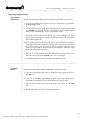
Operating Procedures
Acknowledging
the Alarm
Condition
When the user presses the "ACK" switch to acknowledge an alarm condition, the
following actions will occur:
1.
The control panel's internal audible buzzer will (always) silence.
2.
The acknowledge key's activation is logged into the History Buffer to provide
a time stamped record of the event's occurrence.
3.
The red Alarm LED on the first initiating point reporting an alarm will
change from pulsing at the accelerated rate to a slower rate. The slower rate
is defined as a continuously repeating sequence of 1/2 second 'On' followed
by 1/2 second 'Off'.
!
If there are subsequent initiating points in alarm, the associated red Alarm
LED(s) will change from pulsing at an accelerated rate to "On' steady. All
previously acknowledged point-in-alarm continue to have their red Alarm
LED's 'On' steady.
4.
The two yellow LED's on the bus driver module display acknowledge "ACK"
switch will stop pulsing and extinguish. Any outputs programmed to return
to the normal condition upon pressing the "ACK" switch will return to
normal at this time.
5.
Both yellow LED's on the bus driver module display for the RESET and
signal silence switches will pulse at the accelerated rate. This "guided
prompt" feature notifies the user that the next expected action is to Reset the
system or silence the signals.
___________________________________________________________________________________________
Signal Silence
If Signal Silence option is programmed, the yellow LED for the signal silence
switch will pulse at an accelerated rate. This guided prompt feature notifies the
user that it is possible, but not necessary, to press the SIGNAL SILENCE switch
In the default mode, all signal circuits will silence.
If the user presses the SIGNAL SILENCE switch, the following actions will
occur:
1.
The yellow LED for the SIGNAL SILENCE switch will be pulsing,.
2.
All output signal circuits which have been programmed to silence when the
SIGNAL SILENCE switch is activated (which is all output circuits in the
"default" case) will silence.
19
Technical Manuals Online! - http://www.tech-man.com
Flex 620 System Operation - Revision 5, 11/22/01
_______________________________________________________________________________________________
Resound or
Return of
Signals
The signal silence switch is alternating action switch. If the user subsequently
presses the SIGNAL SILENCE switch again, the signal circuits will activate.
1. The lower yellow LED for the SIGNAL SILENCE switch will extinguish.
2. The yellow LED for the SIGNAL SILENCE switch will pulse.
3. All the output signal circuits which had de-activated will re-activate returning
the system status to the original alarm condition.
___________________________________________________________________________________________
Reset
After the initiating device(s) have been restored (i.e. cleared to normal condition),
the momentary Reset switch should be depressed. When the user presses the
RESET switch the following actions will occur:
1. All signal circuits will deactivate.
2. All output relays circuits programmed for "immediate reset" will deactivate
without delay (** System default **). The control panel will return to the
normal condition.
3. If any output relay circuits are programmed for sequential reset, the highest
circuit so programmed will de-activate first. Four seconds later the next
highest addressed programmed will de-activate. This pattern will continue
until all of the sequentially reset relays have been de-activated.
4. Power will be removed from all initiating input points for four (4) seconds to
restore any latched devices.
5. The RESET key's activation is logged into the History Buffer to provide a
time stamped record of the event's occurrence.
6. The control panel will re-enter into the normal quiescent condition.
20
Technical Manuals Online! - http://www.tech-man.com
Flex 620 System Operation - Revision 5, 11/22/01
_______________________________________________________________________________________________
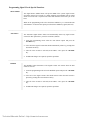
BYPASS
Programming
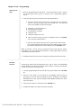
Bypass is used to disable input and output circuits. To use the Bypass option, enter
the proper Access level and press the Bypass key. The LED will flash at a fast rate
indicating that you are in the Bypass circuit selection mode. Select the desired input
and output circuits to be Bypassed and press the Bypass key again. The selected
circuit(s) and Bypass LEDs should flash at the same rate indicating the circuits are
Bypassed. To deselect circuits, press the Bypass switch (Bypass LED Flashes fast)
Deselect circuits and press the Bypass switch again. Circuits deselected will
extinguish.
A. Input Points Bypassed
When the Bypass is utilized it will disable an input circuit that is damaged
and cannot be cleared.
B. Output Signal Circuit Bypassed
Programming any output signal circuit to Bypass will disable the circuit from
activating.
C. Output Relay Circuits bypassed
Programming any output relay circuit to Bypass will disable the circuit from
activating.
D. Building Control Circuits bypassed
Programming any building control circuit to Bypass will disable the circuit
from activating.
E. City Tie(s) bypassed
Programming any City Tie circuit to Bypass will disable the circuit from the
transmitting alarm.
WALKTEST
Programming
WalkTest is designed to allow 1 man to test the fire alarm system. To WalkTest the
system select the WalkTest switch (WalkTest LED flashes fast), select the circuits to
be tested and press the WalkTest switch again. The circuits in WalkTest mode will
flash at the same rate as the WalkTest LED. To deselect circuits, press the WalkTest
switch (WalkTest LED Flashes fast) Deselect circuits and press the WalkTest switch
again. Circuits deselected will extinguish.
A. Input Points Assigned To WalkTest
Any initiating circuits (Conventional Input Modules) may be selected for
WalkTest. Any selected Input circuits will not activate any outputs that are
not selected for WalkTest. When the user has completed selecting the
circuits press the "ENTER" key. Then select the output circuits or press
enter again.
B. Output Signal Circuits Activated During WalkTest
Any indicating circuits (Universal Signal Modules) may be selected for
WalkTest. When the user has completed selecting the circuits press the
"Enter" key. The selected indicating signals will annunciate any alarm with
two short outputs and troubles created will sound one short output.
21
Technical Manuals Online! - http://www.tech-man.com
Technical Manuals Online! - http://www.tech-man.com
This page intentionally blank
Technical Manuals Online! - http://www.tech-man.com
Flex 620 System Operation - Revision 5, 11/22/01
_______________________________________________________________________________________________
Section 3
FlexAlarm 620
Installation
24
Technical Manuals Online! - http://www.tech-man.com
Flex 620 Installation - Revision 5, 11/22/01
___________________________________________________________________________________________
Flex 620 System
Housing
The base Flex 620 system control panel comes complete in two different size
housings. The F624 model is a four bay cabinet enclosure and the F628 is an eight
bay cabinet enclosure. The F624 model holds 4 of the 600 series modules in addition
to the common control, power supply and batteries. When the cabinet used as an
expansion unit, the cabinet accommodates 4 additional modules, an additional power
supply with a battery storage area. The F628 model holds 8 of the 600 series modules
in addition to the common control, power supply and battery storage. As an
expansion cabinet, it can house an additional 8 modules plus a power supply with
available area for battery storage.
The housings are designed with ample field wiring space and conduit knockouts
mounting options. The control panel's main power supply with transformer
independently mounts to the chassis. The unit's dead front design allows all
operation, programming and user interface to take place without exposure of the
system modules or field wiring. Field wiring terminals which the modules plug into
are mounted directly to the backbox for ease of installation and servicing. Modules
can be removed for servicing without disturbing field wiring. Systems are all factory
assembled.
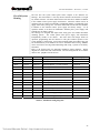
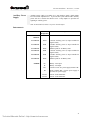
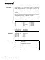
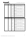
Refer to the flowing table for applicable installation wiring diagrams. Wiring
diagrams are found at the end of this manual. All field wiring must be in accordance
with N.F.P.A. pamphlet #70 article #760.
Drawing #
D-W1142
Issue Date
3/29/94
Part No.
Title
Wiring, Minimum System Flex 620
Module Display P/N
C-W847
3/29/94
30879
Bus Driver Module
C-W845
3/28/94
30868-01
Initiating Module 4 Circuit (CIM-4)
30870-02
C-W845
3/28/94
30868
Initiating Module 8 Circuit (CIM-8)
30870-02
C-W846
3/29/94
30878-01
Indicating Module 4 Circuit (USM-4)
30870-02
C-W846
3/29/94
30878
Indicating Module 8 Circuit (USM-8)
30870-02
C-W848
3/29/94
30873
Relay Module 4 Circuit (RM-4)
30870-03
C-W848
3/29/94
30874
Relay Expander Module (RM-4E)
C-W849
7/7/94
30871
Building Control Module (BC-4)
C-W849
7/7/94
30872
Building Control Expander (BC-4E)
C-W845
3/28/94
30869
Class "A" Adapter
(CIM-SDA)
C-W846
3/29/94
30940
Class "A" Adapter
(USM-SZA)
C-W861
3/31/94
30875
City Tie Extender Module (CTX-4)
C-W856
3/28/94
30889
Main Power Supply 8 Amp (MPS-8)
C-W857
3/28/94
30890
Aux. Power Supply 8 Amps (APS-8)
30870-04
30870-02
Table I-1, Installation Wiring Diagrams
25
Technical Manuals Online! - http://www.tech-man.com
Flex 620 System Operation - Revision 5, 11/22/01
_______________________________________________________________________________________________
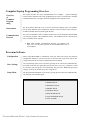
Hardware
Assembly
Systems are all factory assembled. The 600 series modules will be positioned
within a cabinet (reading left to right, top to bottom) in the following order.
Blank dress plates will be supplied for any unused module bays.
1.
2.
3.
4.
5.
6.
CIM(Conventional Input Module - Initiating Module)
USM (Universal Signal Module - Indicating Module)
RM (Relay Module)
BC (Building Control Module)
CTX (City Tie Expander)
APS (Auxiliary Power Supply)
Û Note: Upon receiving control panel, remove all packaging
materials. Inspect for any damage that may have occurred
during shipment. Notify the manufacturer immediately if
damage is detected.
Flex 620
Control Panel
Mounting
Complete the following instructions to mount the Flex 620 control panel. The
instructions are applicable for either the F624 or F628 housings. All control
panel displays as well as the power supply are not installed and are shipped
separately. Refer to drawing D-W1142, Wiring, Minimum System Flex 620.
___________________________________________________________________________________________
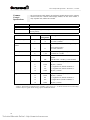
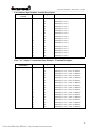
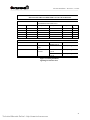
Cabinet Dimensions
F624 (4) Bay Cabinet
Dimensions
Battery Storage
Weight
37.2"H x 24"W x 6"D
8"H x 14.25" x 6"D
approx. 65 lbs
F628 (8) Bay Cabinet
Dimensions
Battery Storage
Weight
52.25"H x 24"W x 6"D
8"H x 14.25" x 6"D
approx. 75 lbs
Table I-2, Cabinet Dimensions
___________________________________________________________________________________________
26
Technical Manuals Online! - http://www.tech-man.com
Flex 620 Installation - Revision 5, 11/22/01
___________________________________________________________________________________________
Cabinet Mounting and Assembly Procedure
1. Unlock the front panel door. Lift up and remove.
2. Remove the mounting screws securing the three horizontal cross rails.
CAUTION !
Protect all cabinet components when mounting the control
panel to the foundation. Failure to cover enclosed circuit
boards from debris (metal shavings, dust etc.) may damage
components.
3.
4.
Secure the cabinet to the mounting foundation. Connect all conduit and secure.
Connect all field wiring. Reference all installation wiring diagrams as required. (All
field wiring must be in accordance with N.F.P.A. pamphlet #70 article #760.) Ensure
the cabinet is clean.
5. Secure the main power supply module (MPS-8 p/n 30889) to the main chassis. Plug in
the battery charger card. If applicable, connect the auxiliary power supply (APS-8) in
accordance with drawings D-W1142, C-W856 and C-W857.
6. Mount the three cross rails and secure (if disassembled).
7. Mount the common control display into the alignment pins of the top cross rail. Mount
the two display (for initiating, indicating, building control module etc.) into alignment
pins of cross rails.
8. Connect the following interconnecting cables (ribbon and power cables). Reference
drawing D-W1142 all applicable wiring diagrams shown in above Table 1.
A. Ribbon cable (p/n 71157) interconnecting the bus driver module (J11) to the common
control display.
B. Ribbon cable (p/n 71158) interconnecting CPU module (ISBX1) and bus driver module
(P1).
C. 4 conductor interconnecting cable (p/n 30881) from CPU module (P3) to the bus driver
module (J13 - CPU power).
Note: All dual part numbers listed below refer to the correct cables for 4 and 8 bay
cabinets respectively
D. Ribbon cable (p/n 71156/71161) interconnecting left display bus and the bus driver
module (J6).
E. Ribbon cable (p/n 71155/71160) interconnecting left I/O module bus with the bus driver
module (J5).
F. Ribbon cable (p/n 71156/71161) interconnecting right display bus and the bus driver
module (J7).
G. Ribbon cable (p/n 77154/71159) interconnecting right I/O module bus with the bus
driver module (J8).
H. Power cable (p/n 30883) from the power supply (J3) to bus driver module (J16).
I.
Power cable (p/n 30882-01) from the power supply (J2) to bus driver module (J12).
9. Plug in battery charger card.
___________________________________________________________________________________________
27
Technical Manuals Online! - http://www.tech-man.com
Flex 620 System Operation - Revision 5, 11/22/01
_______________________________________________________________________________________________
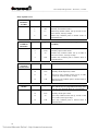
Module Identification and Placement
Module Bus
The Module bus interconnects the I/O modules and the display modules with the
bus driver module. The left I/O modules are linked (via ribbon cable) with the bus
driver module at the J5 connector (labeled I/O Left). The left display modules are
linked (via ribbon cable) with the bus driver module at the J6 connector (labeled
Display Left). The right I/O modules are interconnected at the J8 connector
(labeled I/O Right), and the right display modules are linked at the J6 connector
(labeled Display Right). Each I/O module and its associated display occupies one
bay of the system cabinet.
___________________________________________________________________________________________
Module
Addressing
The Flex 620 system utilizes a unique addressing scheme that allows it to monitor
card locations and supervise the card types within the locations. There are 40 card
locations within the Flex 620 system. Upon initialization, each card location
returns a card type code when polled by the main CPU. Card type codes are fixed
codes that are pre-assigned to each type of module. When a valid card type
response from a card location is detected, a data base is created for it. The specific
card type codes are defined in the programming section of this manual.
Cards # 0 - 7
Card locations 0 through 7 are pre-assigned to the common control section of the
system . These locations define the circuits present in the common control section
(operating display signal circuits, city tie, etc.).
Cards # 8 - 39
Card locations 8 through 39 are the optional modules installed in the cabinet bays
see Figure I-1. Each module (I/O module or display module) has a programmable
addressing jumper which is designated as S1. This jumper must be set according to
the physical placement of the module within its I/O or display bus. If the module
is the first module (vertically top to bottom) within its bus, the S1 jumper should
be located in position 1. If the module is the second module within the bus, its S1
jumpers should be located in position 2, and so on. This jumper placement
determines the card location of the module. Each bus has four card locations preassigned to it. The left I/O bus has card locations 8-11 assigned to it. The left
display bus has card locations 12 - 15, the right I/O bus has card locations 16 - 19
and the right display bus has card locations 20 - 23 assigned to them. This same
sequence is repeated in the expander cabinet accounting for card locations 24 - 39.
Circuit #
Assignments
Circuit assignments are also predefined within the system. Each cabinet bay has 8
circuits reserved for it. From Left to right, top to bottom the circuits are allocated
to each bay in 8 circuit increments. Beginning with the top left bay the circuit
assignments are 1 - 8. The top right bay is assigned circuits 9 - 16, and so on. The
expansion cabinet’s top right bay would have circuits 65 - 72 assigned to it
regardless of the main cabinet‘s size, module placement or the card types installed.
If a card does not require all 8 of the circuit assignments allocated to its bay, the
lowest circuit numbers associated with that bay will be assigned to its circuits.
28
Technical Manuals Online! - http://www.tech-man.com
Flex 620 Installation - Revision 5, 11/22/01
___________________________________________________________________________________________
FLEX 620 CABINET ASSEMBLIES - (4 Bay & 8 Bay Cabinets Shown)
Common Control Section
Cards ID# 0 - 7
D
I
S
P
L
A
Y
Display Module
(Left)
M
O
D
U
L
E
I/O Modules
(Left)
I/O Modules
(Right)
B
U
S
B
U
S
12
8
Ckt. 1-8
jumper to 1
9
Ckt. 17-24
jumper to 2
10
Ckt. 33-40
jumper to 3
11
Ckt. 49-56
jumper to 4
jumper to 1
13
jumper to 2
14
jumper to 3
15
jumper to 4
M
O
D
U
L
E
B
U
S
16
Ckt. 9-16
jumper to 1
17
Ckt. 25-32
jumper to 2
18
Ckt. 41-48
jumper to 3
19
Ckt. 57-64 jumper
to 4
Display Module
(Right)
D
I
S
P
L
A
Y
B
U
S
20
jumper to 1
21
jumper to 2
22
jumper to 3
23
jumper to 4
FLEX 620
Expansion Cabinets
w/Bus Extender
D
I
S
P
L
A
Y
Display Module
(Left)
M
O
D
U
L
E
I/O Modules
(Left)
I/O Modules
(Right)
B
U
S
B
U
S
28
jumper to 1
29
jumper to 2
30
jumper to 3
31
jumper to 4
24
Ckt. 65-72
jumper to 1
25
Ckt. 81-88
jumper to 2
26
Ckt. 97-104
jumper to 3
27
Ckt. 113-120
jumper to 4
M
O
D
U
L
E
B
U
S
32
Ckt. 73-80
jumper to 1
33
Ckt. 89-96
jumper to 2
34
Ckt. 105-112
jumper to 3
35
Ckt. 121-128
jumper to 4
Display Module
(Right)
D
I
S
P
L
A
Y
B
U
S
36
jumper to 1
37
jumper to 2
38
jumper to 3
39
jumper to 4
Figure 3-1, Cabinet Module Locations
29
Technical Manuals Online! - http://www.tech-man.com
Flex 620 System Operation - Revision 5, 11/22/01
_______________________________________________________________________________________________
Main Power
Supply
The main power supply (p/n 30889) is a combination 8 amp system power supply
and battery charger. It provides the system with five supplies (a 24Vdc regulated,
24Vdc unregulated, 12Vdc, 5Vdc and the battery charger). The standard battery
charger is sized to maintain up to 60 AH batteries. The battery charger is designed
to operate during set intervals extending the battery life of the lead acid batteries.
When installing 5 - 20 AH batteries remove R17 (both resistors) from the battery
charger card (P/N 30843). When installing 21 - 40 AH batteries remove R1.
Installation
Diagram
Refer to drawings C-W856 Main Power Supply and D-W1142 Wiring, Minimum
System Flex 620 for installation and cable connections. When applicable, refer to
C-W857 Aux. Power Supply.
___________________________________________________________________________________________
Specifications
Input Voltage
120 VAC 50/60 Hz 3 amps Max. (Optional 220V AC
available)
Output Voltage
24 Volt DC regulated @ 4 Amps - system power, S+ Sand A+ A-{XE "\"Smart Start\""}
24 Volt DC filtered @ 4 Amps - for signal circuit power
5 Volt DC regulated - supply for logic circuits
12 Volt DC regulated @ 2 Amps
Operating Temperature
0 to +49 degrees C
Humidity
85% non-condensing
Interconnects
24 VAC
C+, CBO
(Brown-out Output)
B+, B-
(2) secondary transformer connection
Connection (Red, Black) to Filter Capacitor
Brown Out - connects to auxiliary power supply BI
(Brown-out Input) terminal
(Red, Black) connections to Battery Distribution Block
J4 connector
Not used on F620 System
J3 connector
Interconnects to J16 on bus driver module
J2 connector
Interconnects to J12 on bus driver module (5V, 12V, and
24V supervision)
___________________________________________________________________________________________
30
Technical Manuals Online! - http://www.tech-man.com
Flex 620 Installation - Revision 5, 11/22/01
___________________________________________________________________________________________
Auxiliary Power
Supply
Auxiliary Power supply (p/n 30890) is a 8 amp auxiliary supply, which mounts
into one module expansion slot. It provides the system with 24 VDC auxiliary
power full wave rectified and filtered. Two 4 amp outputs are provided for
signaling or auxiliary power.
Note: Terminals Black, Red are not power limited outputs.
Interconnects
Card APS-8
Terminal
Designation
Description
OUTPUT
J1 connector
RED
J1 connector
BLK
J1 connector
J2 connector
WHT
RED
J2 connector
BLK
J2 connector
WHT
POWER
B+
BBO
BI
24VAC
24VAC
+24VDC auxiliary power (4 amps
signal circuits)
-24VDC auxiliary power (4 amps
signal circuits)
Monitor point for AC/Battery fault
+24VDC auxiliary power (4 amps
signal circuits)
-24VDC auxiliary power (4 amps
signal circuits)
Monitor point for AC/Battery fault
available for
available for
available for
available for
Battery +24V Input
Battery -24V Input
Connect to next aux. power supply terminal “BI”
From terminal "BO” of main power supply or
previous aux. power supply
24VAC from transformer
24VAC from transformer
31
Technical Manuals Online! - http://www.tech-man.com
Flex 620 System Operation - Revision 5, 11/22/01
_______________________________________________________________________________________________
Common
Control
Specifications
Common Control
Input Power
Quiescent Current
Alarm Current
The specifications listed identify the interfacing modules housed in the common
control section; the common control display module, the bus driver module, a
relay expander card, and the CPU module.
24VDC
275 mA
407 mA plus Signal Circuit power plus 2mA for master box or 22 mA for
reverse polarity
Terminal #
Auxiliary Output
1
2
Terminal
Designation
A+
A-
Smoke Detector
Power
3
S+
4
S-
Security Power
5
6
(+)12
(-)12
City Tie
7
M1
8
M2
Description
21 VDC, 2 Amps regulated auxiliary power*
21 VDC Common*
21 VDC @ 125mA, resetable regulated power
*
(4 second reset time)
21 VDC common *
12VDC, 2 Amps regulated power
common for +12VDC
Connections for master box or line reversal
option.
Line Reversal - 24VDC @ 15mA nominal
9
10
11
12
1L1R
1L1
1L2
1L2R
Signal CCT#1, 24V@2A, Style Y or Z
Style Z (+) Return
(+) Signal Power (normal condition) **
(-) Signal Power (normal condition) **
Style Z (-) Return
13
14
15
16
2L1R
2L1
2L2
2L2R
Signal CCT#2, 24V@2A, Style Y or Z
Style Z (+) Return
(+) Signal Power (normal condition) **
(-) Signal Power (normal condition) **
Style Z (-) Return
Signal Circuit 1
Signal Circuit 2
* Note 1: Total load of regulated power including system power, A+ A- and S+S- must not exceed 4 amps.
**Note 2: Style Y signal circuit wiring requires 3.9K EOL resistor.
32
Technical Manuals Online! - http://www.tech-man.com
Flex 620 Installation - Revision 5, 11/22/01
___________________________________________________________________________________________
Relay Expander
Card
The relay expansion module provides four programmable relay circuits with Form
C (normally open) contacts. When connected to the bus driver module this
module provides for Common Alarm, Common Trouble, and Supervisory Alarm
relay. Each relay has a fused common rated at ten (10) amps and provides
positive feedback for status indication. Each relay on the bus driver module
draws 22mA when activated. In normal operation only the trouble relay is
activated. The system initialization determines if the feedback loop is
utilized. A feedback circuit must have less than 50 ohms in loop
resistance. The function of relays (K1 - K4):
•
•
•
•
Installation
Diagram
Relay K1
Common Alarm
Relay K2
Common Trouble (Relay is normally energized)
Relay K3
Common Supervisory
Relay K4
AC failure when dialer is enabled or city tie trouble when
Chicago mode is enabled.
Refer to (drawing # D-W1143) for wiring the Relay Expander Card. No switch
settings are required. Card location identification number is "5".
Cable Connection & Notes
J2 Connector
F1 fuse
F2 fuse
F3 fuse
F4 fuse
Interconnection (ribbon cable) to J17 connector on the
bus driver module
10 Amp overload protection K1 relay
10 Amp overload protection K2 relay
10 Amp overload protection K3 relay
10 Amp overload protection K4 relay
___________________________________________________________________________________________
33
Technical Manuals Online! - http://www.tech-man.com
Flex 620 System Operation - Revision 5, 11/22/01
_______________________________________________________________________________________________
Relay Expander Card
RELAY 1
COMMON
ALARM
RELAY 2
COMMON
TROUBLE
RELAY 3
Terminal #
Designation
Description
1
2
3
1 NO
1 NC
1C
4
1M
Normally open Alarm contact
Normally closed Alarm contact
Alarm relay common contact 10A @ 30 VDC or 220
VAC resistive, fused @ 10 amps.
Alarm relay feedback point to monitor status of
controlled device
Terminal #
Designation
* Relay is shown normally energized (normal
condition)
5
6
7
2 NC
2 NO
2C
8
2M
Normally closed Trouble contact
Normally open Trouble contact
Trouble relay common contact 10A @ 30 VDC or
220 VAC resistive, fused @ 10 amps.
Trouble relay feedback point to monitor status of
controlled device
Terminal #
Designation
Description
9
10
11
3 NO
3 NC
3C
12
3M
Normally open Supervisory contact
Normally closed Supervisory contact
Supervisory relay common contact 10A @ 30 VDC
or 220 VAC resistive, fused @ 10 amps.
Supervisory relay feedback point to monitor status of
controlled device
Terminal #
Designation
COMMON
SUPERVISORY
RELAY 4
SPARE
Description
Note: When the City Tie is programmed in the Chicago mode
the spare relay will transfer during City Tie circuit faults.
13
14
15
4 NO
4 NC
4C
16
4M
Normally open spare contact
Normally closed spare contact
Spare relay common contact 10A @ 30 VDC or 220
VAC resistive, fused @ 10 amps.
Spare relay feedback point to monitor status of
controlled device
34
Technical Manuals Online! - http://www.tech-man.com
Flex 620 Installation - Revision 5, 11/22/01
___________________________________________________________________________________________
The bus driver module contains the circuitry that interfaces with the CPU module
and the system modules. The bus driver module is equipped with two Style Y or
Z, limited energy signaling circuits and a city tie circuit.
Bus Driver
Module
The bus driver module provides the system with the following :
• Controls default alarm bus if the CPU fails
• Monitors system modules for placement
• Monitors system for ground faults
• Watchdog circuit
• Programmable Signal Circuits (1 & 2)
• Auxiliary Power Outputs (A+/A-, S+/S-, +/- 12VDC)
The internal circuitry draws about 18mA from the +24V power supply with both
signal circuits terminated with a 3.9K ohm resistor (with no current draw on the
city tie circuit). Each relay on the bus driver module draws 22mA when activated.
In normal operation only the trouble relay is energized.
The bus driver module contains three jumpers for city tie programming (J1, J2, &
J3) located in the center of the board. These three jumpers are used to select the
reverse polarity or the master box option for the city tie connection.
City Tie
Programming
City Tie Programming Set jumpers as follows:
J1
Reverse Polarity
X
Master Box
X = jumper installed
J2
J3
X
X
Refer to drawings D-W1142, Wiring Minimum System Flex 620 and C-W847,
Bus Driver Module.
Installation
Diagram
Cable Connections
P1 Connector
J5 Connector
J6 Connector
J7 Connector
J8 Connector
J9 Connector
J11 Connector
J12 Connector
J13 Connector
J16 connector
J17 Connector
Interconnect (ribbon cable) to IBX1 on the CPU module
Interconnect (ribbon cable) to Left I/O modules
Interconnect (ribbon cable) to Left Display modules
Interconnect (ribbon cable) to Right Display modules
Interconnect (ribbon cable) to Right I/O modules
Interconnect (ribbon Cable) to Cabinet Expander
Interconnect (ribbon cable) to P1 on the common control display
Cable connector to J2 - Power Supply
Cable connector to P3 - CPU module
Three conductor cable to J3 power supply
Interconnect (ribbon cable) to J2 on the Relay Expander Card
35
Technical Manuals Online! - http://www.tech-man.com
Flex 620 System Operation - Revision 5, 11/22/01
_______________________________________________________________________________________________
CPU Module
The CPU module (or micro processor module) contains the system operating
firmware and non-volatile memory. It provides all the system memory and
processing functions as well as providing the local/remote communications and
supervision. System field programming, via a laptop PC link, is accomplished
utilizing the P2 interface. The CPU module jumper settings are preset at the
factory and do not require any field programming. Do not place any jumpers on
the module.
The settings of DIP switch SW1 regulates the system's baud rate. The switch
settings are preset at the factory; see SW1 default settings table.
The module contains a serial communications port for serial device interface
(Isolated RS-232 Card). To install, the U18 IC must be removed from its socket
and replaced with the interconnecting cable from the Isolated RS-232 Card.
SW1 - Default Settings
S1
S2
S3
S4
S5
S6
S7, S8 Open
S7, S8 Closed
S7 Open, S8 Closed
S7 Closed, S8 Open
LED Indication
All four LED's "On"
D1 "On" only
D2 "On" only
D3 "On" only
D4 "On" only
Open
Do Not Change
Open
Do Not Change
Always Closed
Do Not Change
Open
Do Not Change
Open
Do Not Change
Open
Do Not Change
9600 Baud Rate
4800 Baud Rate
2400 Baud Rate
1200 Baud Rate
DIP Switch SW1 Table
Hardware Reset
not used
not used
not used
not used
Cable Connections:
IBX1 connector
Interconnection (ribbon cable) to P1 connection on the bus
driver module
P2 connector
Interconnection (ribbon cable)
programming link, via laptop PC
P3 connector
Interconnecting cable for CPU power via J13 connector on
the bus driver module
P4 (pins 3 & 4)
System Hardware Reset (momentary short) jumper pins
U18 socket
Interface socket for the 16 pin ribbon cable provided for the
Isolated RS232 Card
36
Technical Manuals Online! - http://www.tech-man.com
for
system
field
Flex 620 Installation - Revision 5, 11/22/01
___________________________________________________________________________________________
Common
Control
Display
The common control display (CCD) is the main interface to the system. The display
(i.e. left bus driver display and right bus driver display) provides the user with all
necessary switches and annunciation points to maintain and monitor the system.
Alarm, supervisory and trouble conditions are indicated by dedicated LED's and the
internal sounder. LED annunciation is also provided for AC power, PreAlarm, (2)
signal circuits, City Tie connection and Bypass.
Installation
Diagram
Refer to (drawing # D-W1142) Wiring, F620 Minimum System. The 34 pin ribbon
cable (p/n 71157) interconnects the CCD to the bus driver module (J11 connector).
Power Requirements
•
•
•
2mA operating current
1mA for each Red LED (ON)
6mA for each Yellow or Green LED (ON)
Note: When the CIM-4 and CIM-8 circuits are programmed as AND zones types
use only Gamewell 70133,70134 and 70135 detectors.
___________________________________________________________________________________________
37
Technical Manuals Online! - http://www.tech-man.com
Flex 620 System Operation - Revision 5, 11/22/01
_______________________________________________________________________________________________
System I/O Components (600 Series)
Conventional
Input Module
The conventional input module (CIM) consists of up to 3 assemblies. The I/O
Circuit module, the Style D (Class A) adapter, and the Alarm Display. To view a
comprehensive listing of compatible devices with the Flex 620 control panel, refer to
Figure 3-3, Compatible Initiation Devices found at the end of this section. Also refer
to Figure 3-4, Compatible Auxiliary Devices for comprehensive listing of auxiliary
devices.
Circuit
Module
The circuit module provides four (CIM-4) or eight (CIM-8) conventional circuits.
All circuits operate on the Style B (Class B) mode of operation. The End of Line
Resistor (EOLR) required is 3.9k ohms with a maximum of 25 ohms line resistance.
Programming jumper (S1) is provided on each board for setting the vertical
position/address of the card (S1-1 through S1-4). The I/O circuit module uses the
lower terminal block and connects via cables to the bus driver module. The
conventional input module and its display require one bay of the F620 system.
Note: When the CIM-4 and CIM-8 circuits are programmed as AND zone types use
only Gamewell model 70133,70134 and 70135 detectors.
Style "D"
Adapter
The style D adapter card (CIM-SDA) provides 4 or 8 Style D (Class A) circuits to
the I/O circuit module. When the Style D adapter is used the EOLR's are not
required. The style D adapter uses the upper terminal block, and is cabled to the I/O
circuit module.
Display
Module
The display module provides eight (8) red circuit alarm LED's, eight (8) yellow
circuit trouble LED's.
Eight (8) circuit tactile switches are provided for
programming, Bypass and WalkTest functions. The display module connects (via
the display bus) to the bus driver module. The physical location of the display is set
by the addressing jumper S1. Ensure addressing jumper is set according to its
physical location in the cabinet and matches associated I/O module address jumper
setting. Refer to Figure I-1, Cabinet Module Locations.
38
Technical Manuals Online! - http://www.tech-man.com
Flex 620 Installation - Revision 5, 11/22/01
___________________________________________________________________________________________
Conventional Input Module Terminal Description
Bottom card (30868)
CIM-8
Terminal #
1
2
3
4
5
6
7
8
9
10
11
12
13
14
15
16
Designation
1L1
1L2
2L1
2L2
3L1
3L2
4L1
4L2
5L1
5L2
6L1
6L2
7L1
7L2
8L1
8L2
Description
Initiating CCT # 1 (-)
Initiating CCT #1 (+)
Initiating CCT # 2 (-)
Initiating CCT #2 (+)
Initiating CCT # 3 (-)
Initiating CCT #3 (+)
Initiating CCT # 4 (-)
Initiating CCT #4 (+)
Initiating CCT # 5 (-)
Initiating CCT #5 (+)
Initiating CCT # 6 (-)
Initiating CCT #6 (+)
Initiating CCT # 7 (-)
Initiating CCT #7 (+)
Initiating CCT # 8 (-)
Initiating CCT #8 (+)
Class "A" Adapter -Conventional Input Module - Terminal Description
Top Card (30869)
(CIM-SDA)
Terminal #
1
2
3
4
5
6
7
8
9
10
11
12
13
14
15
16
Designation
1L1
1L2
2L1
2L2
3L1
3L2
4L1
4L2
5L1
5L2
6L1
6L2
7L1
7L2
8L1
8L2
Description
Initiating CCT #1 (-) Class "A" Return
Initiating CCT #1 (+) Class "A" Return
Initiating CCT #2 (-) Class "A" Return
Initiating CCT #2 (+) Class "A" Return
Initiating CCT #3 (-) Class "A" Return
Initiating CCT #3 (+) Class "A" Return
Initiating CCT #4 (-) Class "A" Return
Initiating CCT #4 (+) Class "A" Return
Initiating CCT #5 (-) Class "A" Return
Initiating CCT #5 (+) Class "A" Return
Initiating CCT #6 (-) Class "A" Return
Initiating CCT #6 (+) Class "A" Return
Initiating CCT #7 (-) Class "A" Return
Initiating CCT #7 (+) Class "A" Return
Initiating CCT #8 (-) Class "A" Return
Initiating CCT #8 (+) Class "A" Return
39
Technical Manuals Online! - http://www.tech-man.com
Flex 620 System Operation - Revision 5, 11/22/01
_______________________________________________________________________________________________
Universal
Signal Circuit
Module
The indicating signal circuit modules (USM-4, USM-8) consists of up to three (3)
assemblies. The I/O Signal Module, Style "Z" Adapter, and the Alarm Display Card.
To view a comprehensive listing of compatible devices with the Flex 620 control
panel, refer to Figure I-4, Compatible Indicating Appliances found at the end of this
section. Also reference to Figure I-5, Wiring Guidelines Signaling Circuit Wire Sizes.
Signal Circuit
Module
The signal circuit module provides four (4) or eight (8), 2 amp DC, current limited
analog signaling circuits. All circuits operate on the Style Y (Class B) mode of
operation. The end of line resistor (EOLR) is 3.9K ohm. Programming jumper (S1)
is provided on each board for setting the vertical position/address of the card (J1
through J4). The I/O signal module uses the lower terminal block and connects via
cable to the bus driver module. Each universal signal module communicates via the
Module bus and requires one bay position each.
The SIGNAL I/O board has an option that allows programming of the signal circuits
to be operable under Default Alarm Mode. A DIP switch (S2) is provided on the
module to select which signaling circuits operate under default alarm mode. To set
the circuits that are active, close their respective switch on S2. I.E.: Switch 1 for
circuit 1, Switch 2 for circuit 2, through Switch 8 for circuit 8.
Style "Z"
Adapter
The Style D adapter (USM-SZA) card provides four (4) or eight (8) Style Z (Class A)
circuits to the I/O signal card. When the Style Z adapter is used the EOLR's are not
required. The Style Z adapter uses the upper terminal block, and is cabled to the I/O
signal module.
Display
Module
The alarm display module provides eight (8) red zone alarmed LED's, eight (8) yellow
zone trouble LED's. Eight (8) zone tactile switches are provided for programming,
Bypass and WalkTest functions. Card slots are furnished for zone description,
comments. The display module connects (via the display bus) to the bus driver
module. The physical location of the display is set by the addressing jumper S1.
Ensure addressing jumper is set according to its physical location in the cabinet and
matches associated I/O module address jumper setting. Refer to Figure I-1, Cabinet
Module Locations.
40
Technical Manuals Online! - http://www.tech-man.com
Flex 620 Installation - Revision 5, 11/22/01
___________________________________________________________________________________________
Universal Signal Circuit Module Terminal Description
Bottom card (30878)
USM-8
Terminal #
Designation
1
2
3
4
5
6
7
8
9
10
11
12
13
14
15
16
1AL1
1AL2
2AL1
2AL2
3AL1
3AL2
4AL1
4AL2
5AL1
5AL2
6AL1
6AL2
7AL1
7AL2
8AL1
8AL2
Description
Indicating CCT #1 (+) output
Indicating CCT #1 (-) output
Indicating CCT #2 (+) output
Indicating CCT #2 (-) output
Indicating CCT #3 (+) output
Indicating CCT #3 (-) output
Indicating CCT #4 (+) output
Indicating CCT #4 (-) output
Indicating CCT #5 (+) output
Indicating CCT #5 (-) output
Indicating CCT #6 (+) output
Indicating CCT #6 (-) output
Indicating CCT #7 (+) output
Indicating CCT #7 (-) output
Indicating CCT #8 (+) output
Indicating CCT #8 (-) output
Class "A" Adapter - Universal Signal Module - Terminal Description
Top Card (30940)
(USM-SZA)
Terminal #
Designation
1
2
3
4
5
6
7
8
9
10
11
12
13
14
15
16
1AL1
1AL2
2AL1
2AL2
3AL1
3AL2
4AL1
4AL2
5AL1
5AL2
6AL1
6AL2
7AL1
7AL2
8AL1
8AL2
Description
Indicating CCT #1 (+) output Class "A" return
Indicating CCT #1 (-) output Class "A" return
Indicating CCT #2 (+) output Class "A" return
Indicating CCT #2 (-) output Class "A" return
Indicating CCT #3 (+) output Class "A" return
Indicating CCT #3 (-) output Class "A" return
Indicating CCT #4 (+) output Class "A" return
Indicating CCT #4 (-) output Class "A" return
Indicating CCT #5 (+) output Class "A" return
Indicating CCT #5 (-) output Class "A" return
Indicating CCT #6 (+) output Class "A" return
Indicating CCT #6 (-) output Class "A" return
Indicating CCT #7 (+) output Class "A" return
Indicating CCT #7 (-) output Class "A" return
Indicating CCT #8 (+) output Class "A" return
Indicating CCT #8 (-) output Class "A" return
41
Technical Manuals Online! - http://www.tech-man.com
Flex 620 System Operation - Revision 5, 11/22/01
_______________________________________________________________________________________________
Relay Module
The relay module (RM-4, RM-8) consists of three (3) assemblies. The I/O Relay
Module, the Relay Expander, and the Control Display.
Relay Circuit
Module
The relay module consists of four (4) form "C" 10 amp fused relay contacts. The
module also provides four (4) feedback input points (switched negative) using 3.9K
ohm resistors in parallel with an open feedback contact. If the feedback points are
connected the LED's on the control display will follow the status of the feedback input
point. A (-) connected directly to the feedback point will actuate the Red LED and a
(-) through the 3.9k resistor will actuate the Green LED. Otherwise the LED's on the
display will follow the status of the relay. Programming jumper (S1) is provided on
each board for setting the vertical position/address of the card (S1-1 through S1-4).
The relay module uses the lower terminal block and cables to the bus driver module.
Each position on the Module bus can accommodate an expanded relay module.
Relay
Expander
Module
The relay expander provides the addition of four (4) supplementary form "C" 10 amp
fused relay contacts. The module also provides four (4) feedback input points
(switched negative) using 3.9K ohm resistors in parallel with an open feedback
contact. If the feedback points are connected (when the system is initialized) the
LED's on the control display will follow the status of the feedback input point.
Otherwise the LED's on the display will follow the status of the relay. The relay
expander module uses the upper terminal block and cables to the I/O relay module.
Relay Display
Module
The control display module provides eight (8) red relay activated LED's, eight (8)
green relay normal LED's. Eight (8) circuit tactile switches are provided for
programming and Bypass functions. Card slots are furnished for relay descriptions
and comments. The display module connects (via the display bus) to the bus driver
module. The physical location of the display is set by the addressing jumper S1.
Ensure addressing jumper is set according to its physical location in the cabinet and
matches associated I/O module address jumper setting. Refer to Figure I-1, Cabinet
Module Locations.
___________________________________________________________________________________________
42
Technical Manuals Online! - http://www.tech-man.com
Flex 620 Installation - Revision 5, 11/22/01
___________________________________________________________________________________________
Relay Module
RM-4
(30873)
Terminal
Number
Designator
1
2
3
4
5
6
7
8
9
10
11
12
13
14
15
16
1 NO
1 NC
1C
1M
2 NO
2 NC
2C
2M
3 NO
3 NC
3C
3M
4 NO
4 NC
4C
4M
Description
Form C normally open contact
Form C normally closed contact
Form C common contact 10A @ 30VDC or 220VAC resistive, fused @ 10A.
CCT #1 Relay feedback point to monitor status of controlled device
Form C normally open contact
Form C normally closed contact
Form C common contact 10A @ 30VDC or 220VAC resistive, fused @ 10A.
CCT #2 Relay feedback point to monitor status of controlled device
Form C normally open contact
Form C normally closed contact
Form C common contact 10A @ 30VDC or 220VAC resistive, fused @ 10A.
CCT #3 Relay feedback point to monitor status of controlled device
Form C normally open contact
Form C normally closed contact
Form C common contact 10A @ 30VDC or 220VAC resistive, fused @ 10A.
CCT #4 Relay feedback point to monitor status of controlled device
Relay Expansion Module
RM-4E
(30874)
Terminal
#
Designator
1
2
3
4
5
6
7
8
9
10
11
12
13
14
15
16
5 NO
5 NC
5C
5M
6 NO
6 NC
6C
6M
7 NO
7 NC
7C
7M
8 NO
8 NC
8C
8M
Description
Form C normally open contact
Form C normally closed contact
Form C common contact 10A @ 30VDC or 220VAC resistive, fused @ 10A .
CCT #5 Relay feedback point to monitor status of controlled device
Form C normally open contact
Form C normally closed contact
Form C common contact 10A @ 30VDC or 220VAC resistive, fused @ 10A.
CCT #6 Relay feedback point to monitor status of controlled device
Form C normally open contact
Form C normally closed contact
Form C common contact 10A @ 30VDC or 220VAC resistive, fused @ 10A.
CCT #7 Relay feedback point to monitor status of controlled device
Form C normally open contact
Form C normally closed contact
Form C common contact 10A @ 30VDC or 220VAC resistive, fused @ 10A.
CCT #8 Relay feedback point to monitor status of controlled device
43
Technical Manuals Online! - http://www.tech-man.com
Flex 620 System Operation - Revision 5, 11/22/01
_______________________________________________________________________________________________
Building
Control Module
The building control module (BC) consists of three (3) assemblies. The I/O Building
Control Module, the Building Control Expander, and the Building Control
Display/Switch Module.
Building
Control
Circuit
Module
The building control module consists of eight (8) form A/B (jumper programmable)
10 amp relays set up in four (4) "ON" relays and four (4) "OFF" relays, with a 10 amp
fused common. Each relay (ON and OFF) is programmable for N/O or N/C contacts
by removing the A or B jumper. Remove the A jumper for N/C contacts or the B
jumper for N/O contacts. The module also provides four (4) feedback input points
(switched negative) using 3.9K ohm resistors in parallel with an open feedback
contact. A (-) connected directly to the feedback point will actuate the Red LED and a
(-) through the 3.9k resistor will actuate the Green LED. Should the feedback points
be connected the LED's on the building control display will follow the status of the
feedback input point. Otherwise the LED's on the display will follow the status of the
active relay. Programming jumper (S1) is provided on each board for setting the
vertical position/address of the card (S1-1 through S1-4). The building control
module uses the lower terminal block and cables to the bus driver module. The
building control module uses one slot in the Module bus.
Building
Control
Expander
The building control expander module provides an additional eight (8) form A/B
(jumper programmable) 10 amp relays set up in four (4) "ON" relays and four (4)
"OFF" relays, with a 10 amp fused common. The module functions identically as the
building control module - providing four (4) feedback input points (switched negative)
using 3.9k ohm resistors in parallel with an open feedback contact. The expander
module mounts to the building control module (via standoffs) and uses the upper
terminal block and cables to the I/O building control module.
Building
Control
Display/Switch
Module
The control display module provides eight (8) red "OFF" relay activated LED's, eight
(8) green "ON" relay activated LED's. Eight (8) three (3) position (AUTO,ON,OFF)
rotary switches are provided for manual control of the I/O building control module
and building control expander. Eight (8) circuit tactile switches are provided for
programming and Bypass functions. Card slots are provided for building control
description, comments. The building control display module mounts to the display
door and is cabled to the bus driver module. The physical location of the display is
set by the addressing jumper S1. Ensure addressing jumper is set according to its
physical location in the cabinet and matches associated I/O module address jumper
setting. Refer to Figure I-1, Cabinet Module Locations.
___________________________________________________________________________________________
A
ON
B
ON relay
COM
A
OFF
B
OFF relay
Figure 3.2 Typical building control circuit relay configuration
44
Technical Manuals Online! - http://www.tech-man.com
Flex 620 Installation - Revision 5, 11/22/01
___________________________________________________________________________________________
Building Control Module
BC-4 (30871)
BC-4E (30872)
Terminal #
Designation
Description
1
2
3
4
1 ON
1 COM
1 OFF
1 MON
5
6
7
8
2 ON
2 COM
2 OFF
2 MON
9
10
11
12
3 ON
3 COM
3 OFF
3 MON
13
14
15
16
4 ON
4 COM
4 OFF
4 MON
CCT 1 relay N/O contact - remove the W2 B Jumper
Common for CCT1 relays (terminals 1 & 3)
CCT 1 relay N/C contact - remove the W3 A Jumper
Monitor point for CCT1 (requires 3.9K resistor to (-)
when used)
CCT 2 relay N/O contact - remove the W6 B Jumper
Common for CCT2 relays (terminals 5 & 7)
CCT 2 relay N/C contact - remove the W7 A Jumper
Monitor point for CCT2 (requires 3.9K resistor to (-)
when used)
CCT 3 relay N/O contact - remove the W10 B Jumper
Common for CCT 3 relays (terminals 9 & 11)
CCT 3 relay N/C contact - remove the W11 A Jumper
Monitor point for CCT 3 (requires 3.9K resistor to (-)
when used)
CCT 4 relay N/O contact - remove the W14 B Jumper
Common for CCT 4 relays (terminals 13 & 15)
CCT 4 relay N/C contact - remove the W15 A Jumper
Monitor point for CCT 4 (use 3.9K to (-) when req.)
Terminal #
Designation
Description
1
2
3
4
5 ON
5 COM
5 OFF
5 MON
5
6
7
8
6 ON
6 COM
6 OFF
6 MON
9
10
11
12
7 ON
7 COM
7 OFF
7 MON
13
14
15
16
8 ON
8 COM
8 OFF
8 MON
CCT 5 relay N/O contact - remove the W2 B Jumper
Common for CCT 5 relays (terminals 1 & 3)
CCT 5 relay N/C contact - remove the W3 A Jumper
Monitor point for CCT 5 (requires 3.9K resistor to (-)
when used)
CCT 6 relay N/O contact - remove the W6 B Jumper
Common for CCT6 relays (terminals 5 & 7)
CCT 6 relay N/C contact - remove the W7 A Jumper
Monitor point for CCT6 (requires 3.9K resistor to (-)
when used)
CCT 7 relay N/O contact - remove the W10 B Jumper
Common for CCT 7 relays (terminals 9 & 11)
CCT 7 relay N/C contact - remove the W11 A Jumper
Monitor point for CCT 7 (requires 3.9K resistor to (-)
when used)
CCT 8 relay N/O contact - remove the W14 B Jumper
Common for CCT 8 relays (terminals 13 & 15)
CCT 8 relay N/C contact - remove the W15 A Jumper
Monitor point for CCT 8 (use 3.9K to (-) when req.)
45
Technical Manuals Online! - http://www.tech-man.com
Flex 620 System Operation - Revision 5, 11/22/01
_______________________________________________________________________________________________
City Tie
Extender
Module
The city tie extender module (CTX) consists of two (2) assemblies. These include the
I/O City Tie Extender Module and Alarm Display Module.
City Tie
Extender
Circuit
Module
The I/O city tie extender module provides for four (4) additional reverse polarity city
tie circuits. These circuits can be programmed for multiple buildings being controlled
by one panel, multiple entrances, or different types of alarms including supervisory or
building notification. Each circuit transmits trouble for the zones associated to its
circuit. Programming jumper (S1) is provided on each board for setting the vertical
position/address of the card (S1-1 through S1-4). The city tie extender module uses
the lower terminal block and cables to the bus driver module. This module uses one
slot in the Module bus.
Display
Module
The display module provides eight (8) red circuit alarm LED's, eight (8) yellow circuit
trouble LED's. Eight (8) circuit tactile switches are provided for programming and
Bypass functions. A card slot is furnished for circuit description and comments. The
display module mounts to the display door and is cabled to the bus driver module.
The physical location of the display is set by the addressing jumper S1. Ensure
addressing jumper is set according to its physical location in the cabinet and matches
associated I/O module address jumper setting. Refer to Figure I-1, Cabinet Module
Locations.
City Tie Expander Module
4 Circuits (30875)
CTX-4
Terminal #
Designation
1
2
3
4
5
6
7
8
9
10
11
12
13
14
15
16
1M1
1M2
2M1
2M2
3M1
3M2
4M1
4M2
5M1
5M2
6M1
6M2
7M1
7M2
8M1
8M2
46
Technical Manuals Online! - http://www.tech-man.com
Description
Circuit 1 (+) line connection
Circuit 1 (-) line connection
Circuit 2 (+) line connection
Circuit 2 (-) line connection
Circuit 3 (+) line connection
Circuit 3 (-) line connection
Circuit 4 (+) line connection
Circuit 4 (-) line connection
not used
not used
not used
not used
not used
not used
not used
not used
Flex 620 Installation - Revision 5, 11/22/01
___________________________________________________________________________________________
Initial System Startup
CAUTION !
Connect primary AC power to the system before
connecting the battery/standby power source.
1.
Connect primary AC supply (120VAC 50/60 Hz 3 amps).
2.
Activate main power. Press the "Power On" tactile switch.
3.
The "Power ON" green LED starts to pulse (15 second duration).
4.
"Battery Fault" LED flashes. Connect the battery positive and negative
leads.
5.
At the completion of the "Power On" process, each conventional
zone circuit LED will come 'On' for a four second period confirming
circuit is reset during the power up sequence.
6.
System is at idle, the normal quiescent condition. The "Power On"
is illuminated.
___________________________________________________________________________________________
SmartStart
1.
Activate main power. The "Power ON" green LED starts to pulse
(15 second duration). During this time press the "Power On" tactile
switch.
2.
System will commence an initialization process (i.e. SmartStart).
The "Enter" key will begin to flash. Press "Enter" again confirming
the SmartStart initialization.
Û
Note: If the "Enter" key is not pressed, the system will not initialize.
3.
At the completion of the initialization process, each conventional
zone circuit LED will come 'On' for a four second period confirming
circuit is reset during the power up sequence.
4.
System is initialized. "Power ON" green LED illuminated.
47
Technical Manuals Online! - http://www.tech-man.com
Flex 620 System Operation - Revision 5, 11/22/01
_______________________________________________________________________________________________
FLEX 600 CONTROL PANEL
COMPATIBLE SMOKE DETECTORS & BASES
PART#/IDENTIFIER
DEVICE
DESCRIPTION
DETECTOR
QTY/CCT
30780-01/30780-01
Z77B
STANDARD BASE
F7, D9, R7, RT7
25
30780-02/30780-02
Z77D
STANDARD BASE W/ REMOTE
F7, D9, R7, RT7
25
30780-03/30780-03
Z77R
STANDARD BASE W/ REMOTE &
RELAY
F7, D9, R7, RT7
25
30780-04/30780-04
Z77F
STANDARD BASE
STANDBY, REMOTE
W/FLASH
F7, D9, R7, RT7
25
30780-05/30780-05
Z77FR
STANDARD BASE W/FLASH
STANDBY, REMOTE & RELAY
F7, D9, R7 RT7
25
71036
SERIES 60 - 4“ DETECTOR BASE
71033, 71034, 71035
25
71086
SERIES 60 - 6“ DETECTOR BASE
71033, 71034, 71035
25
70891 / (HB-4)
STANDARD BASE (SMOKE)
70884,70885
25
70886/(HD-3)
70892 /(HB-13)
STANDARD BASE W/RELAY (SMOKE)
70884,70885
70886/(HD-3)
25
70893
STANDARD BASE (HEAT DETECTOR)
70887,70888,
70889,70890
MAX
AL.
CURRENT
100 MA
70894 /(HB-18)
STANDARD BASE W/LATCHING LED (HEAT
DETECTOR)
70887,70888,
70889,70890
MAX
AL.
CURRENT
100 MA
69121/69124
LINEAR BEAM SMOKE DETECTOR
1 SET
Figure 3-3, Compatible Smoke Detectors
FLEX 600 CONTROL PANEL
COMPATIBLE AUXILIARY DEVICES
PART NUMBER
DESCRIPTION
30954
4 WIRE IONIZATION DUCT DETECTOR, APOLLO
30955
4 WIRE, PHOTOELECTRIC DUCT DETECTOR< APOLLO
30069
END OF LINE SUPERVISORY RELAY
30844
4 WIRE, DUCT SMOKE DETECTOR
30845
4 WIRE, DUCT SMOKE DETECTOR
Figure 3-4, Compatible Auxiliary Devices
FLEX 600 CONTROL PANEL
COMPATIBLE INITIATING DEVICES FOR “AND“ ZONES
71036
SERIES 60 - 4“ DETECTOR BASE
71033, 71034, 71035
25
71086
SERIES 60 - 6“ DETECTOR BASE
71033, 71034, 71035
25
48
Technical Manuals Online! - http://www.tech-man.com
Flex 620 Installation - Revision 5, 11/22/01
___________________________________________________________________________________________
FLEX 600
COMPATIBLE INDICATING APPLIANCES
PART
NUMBER
MODEL NUMBER
DESCRIPTION
CURRENT
70874
MB-G6-24-R
MOTORBELL 6"
.030
70875
MB-G10-24-R
MOTORBELL 10"
.030
71557
RSP-2430-VFR
30 Cd Strobe Adapter Red
.124
71631
SRP-2475-VFR
75 Cd Strobe Adapter Red, Sync.
.215
71558
RSP-2475-VFR
75 Cd Strobe Adapter Red
.200
71561
SRP-24110-HFR
110 Cd Strobe Adapter Red
.250
71586
CSX10-24-DC-R
10” SS Exp indoor Red..
.500
71587
CSXG10-24DC-R
10” SS Exp outdoor Red..
.500
71581
CH-BF1-R
Chime SS/Vib Red
.020
71585
CH-CF1-W
Chime SS/Vib ceiling white
.020
68460-01
CH-DF1-R
Chime Vibrating
.020
71583
CH-CF1-LS-24-VFR
Chime SS/Vib Red
.100
71300
CH-DF1-LS-24-VFR
Chime SS/Vib Red
.100
71301
CH-DF1-LSM-24-VFR
Chime SS/Vib Red
.135
71584
CH-CF1-MS-24-CFW
Chime SS/Vib White
.155
71302
CH-DF1-MS-24-VFR
Chime SS/Vib Red
.155
71582
CH-CF1-IS-24-CFW
Chime SS/Vib White
.245
71303
CH-DF1-IS-24-VFR
Chime SS/Vib Red
.245
71548
SM-12/24-R
Single Circuit Sync Module
.025
71549
DSM-12/24-R
Dual or Class A Sync Module
.038
70871
MIZ-24-R
Mini Horn Red
.017
70873
MIZ-24-W
Mini Horn White
.017
71287
MIZ-24-LS-VFR
Mini Horn/Strobe 15 Cd
.092
71288
MIZ-24-LSM-VFR
Mini Horn/Strobe 15/75 Cd
.127
71289
MIZ-24-MS-VFR
Mini Horn/Strobe 30 Cd
.147
71290
MIZ-24-IS-VFR
Mini Horn/Strobe 75 Cd
.237
71138
MT-12/24-R
Multi-tone Horn Red
See DS851
71573
AMT-12/24-R
Multi-tone Horn Red 3 Input
See DS851
71614
MT4-12/24-R
Multi-tone Horn Red Surface
See DS851
71292
MT-24-LS-VFR
Multi-tone Horn/Strobe Red 15 Cd
See DS851
71574
AMT-24-LS-VFR
Multi-tone Horn/Strobe Red 15 Cd 3 input
See DS851
71295
MT-24-IS-VFR
Multi-tone Horn/Strobe Red 75 Cd
See DS851
71575
AMT-24-IS-VFR
Multi-tone Horn/Strobe Red 75 Cd 3 input
See DS851
71293
MT-24-LSM-VFR
Multi-tone Horn/Strobe Red 15/75 Cd
See DS851
71576
AMT-24-LSM-VFR
Multi-tone Horn/Strobe Red 15/75 Cd 3 input
See DS851
71294
MT-24-MS-VFR
Multi-tone Horn/Strobe Red 30 Cd
See DS851
49
Technical Manuals Online! - http://www.tech-man.com
Flex 620 System Operation - Revision 5, 11/22/01
_______________________________________________________________________________________________
FLEX 600
COMPATIBLE INDICATING APPLIANCES (Cont.)
PART
NUMBER
MODEL NUMBER
DESCRIPTION
CURRENT
71140
MT-24-WM-VFR
Multi-tone Horn/Strobe Red 110 Cd
See DS851
71426
MT-24-SL-VFR
Multi-tone Horn/Strobe Red 15 Cd Sync
See DS851
71427
MT-24-SLM-VFR
Multi-tone Horn/Strobe Red 15/75 Cd Sync
See DS851
71550
RS-2415-VFR
Strobe 15 Cd
.074
71553
RS-241575-VFR
Strobe 15/75 Cd
.100
71552
SRP-2415-VFR
Strobe 15 Cd Plate mount Sync
.096
71551
SR-2415-VFR
Strobe 15 Cd Sync
.096
71569
RSP-241575-VFR
Strobe 15/75 Cd Plate Mount
.100
71554
SRP-241575-VFR
Strobe 15/75 Cd Plate Mount Sync
.138
71555
SR-241575-VFR
Strobe 15/75 Cd Sync
.138
71557
RSP-2430-VFR
Strobe 30 Cd Plate mount
.124
71556
RS-2430-VFR
Strobe 30 Cd
.124
71558
RSP-2475-VFR
Strobe 75 Cd Plate mount
.200
71559
RS-2475-VFR
Strobe 75 Cd
.200
71616
SR-2475-VFR
Strobe 75 Cd Sync
.200
71560
RS-24110-HFR
Strobe 110 Cd
.200
71561
SRP-24110-HFR
Strobe 110 Cd Plate mount Sync
.200
71562
SR-24110-HFR
Strobe 110 Cd Sync
.200
71543
AS-2415-VFR
Horn/Strobe 15 Cd
.093
71544
AS-241575-VFR
Horn/Strobe 15/75 Cd
.121
71545
AS-2430-VFR
Horn/Strobe 30 Cd
.126
71546
AS-2475-VFR
Horn/Strobe 75 Cd
.239
71547
AS-24110-HFR
Horn/Strobe 110 Cd
.269
Table I-2
50
Technical Manuals Online! - http://www.tech-man.com
Flex 620 Installation - Revision 5, 11/22/01
___________________________________________________________________________________________
WIRING GUIDELINES
SIGNALLING CIRCUIT WIRE SIZES 24 VOLT DC PARALLEL
WIRE RESISTANCE
AWG
OHM/1000
PAIR IN DISTANCE TO LAST DEVICE
(MAXIMUM LINE LOSS 10%)
0.5amp
1.0amp
1.5amp
18
16
14
12
10
6.5
4.1
2.6
1.6
1.0
400'
620'
1000'
1600'
2500'
CIRCUIT CHARACTERISTICS
CIRCUIT
EOL
INITIATION
SIGNAL
3.9 K ohm 1/2
watt
3.9 K ohm
1/2 watt
200'
300'
500'
800'
1250'
130'
210'
330'
520'
840'
LINE
RESISTANCE
50 ohm
CABLE TYPE
4.8 ohm
@0.5a
1.2 ohm
@2.0a
2.0am
p
100'
160'
250'
400'
620'
strait lay - 18 ga
strait lay - 14 ga
strait lay - 12 ga
Figure I-5, Wiring Guidelines
Signaling Circuit Wire Sizes
51
Technical Manuals Online! - http://www.tech-man.com
Technical Manuals Online! - http://www.tech-man.com
Section 4
FlexAlarm 620
Programming
Technical Manuals Online! - http://www.tech-man.com
Programming Overview - FlexAlarm 620
Û NOTE: During all levels of programming, the system trouble relay
will generate a trouble condition, indicating an 'off normal' condition.
Notify all key personnel, monitoring companies and municipalities
before proceeding.
____________________________________________________________________________________________
Programming
Overview
Programming the system configuration is accomplished through the Common Control
Display (CCD) tactile switches. How the program is configured defines how the
system operates and is application specific. Every programming operation has been
designed to follow the same basic pattern of steps. Once one programming operation
is completed, the user can apply that knowledge to all of the other programmable
features.
Functional
Key Switch
Labels
The common control legend strips (identifying each of the display's key function
designators with associated LED's) have additional programming text printed on the
reverse side. The programming text identifies the function of the tactile key switches
while in the programming mode. Subsequent to entering the programming mode,
remove each of the 4 legend strips (pulled out from the top of the column) "reverse"
each legend strip so that the back side is visible. Reinsert each strip back into its
original "pocket" on the CCD. The CCD's keys are now labeled for programming
mode.
1. Each labeled key function switch on the CCD has an 'Upper' and a 'Lower' LED
associated with it. To choose a particular option, press the tactile key switch
which is associated with the LED.
A.
When the key is pressed the 1st time, the 'Upper' LED turns "On".
B.
When the key is pressed the 2nd time, the 'Upper' LED turns "Off",
and the 'Lower' LED turns "on".
2. Each time the key switch is pressed the LED will toggle back and forth.
3. If a completely different key is pressed , the LED which is currently "On" will turn
"Off", and the 'Upper' LED on the new key will turn "On".
4. When the desired programming option has been selected, press the "ENTER" key
to select the choice.
Selecting
Options
Point Selection
Depending on the option selected, various other LED's on the input point cards,
output signal cards, output relay cards and/or building control cards will turn on to
indicate the inputs and outputs that are active.
A.
To add new points, press the key associated with the point until its
corresponding LED turns "On".
B.
To remove a point, press the key associated with the point until its
corresponding LED turns "Off".
C.
When all changes to a particular option are completed, press the
"ENTER" key to save your changes.
D.
To program a different option, repeat the process from above steps # 1
through 4. If all programming changes are completed, press the
"ENTER" key twice to exit PROGRAM mode and return to IDLE
mode.
Û NOTE: Reverse the display legend strips back to the "Standard Operating"
labeling side after exiting the programming mode.
Technical Manuals Online! - http://www.tech-man.com
Flex 620 Programming - Revision 5, 11/22/01
______________________________________________________________________________________________
Programming Options
The following options can be programmed from the F620 control panel keypad.
Input Circuit
Types
A. Fire Alarm Control Panel (FACP) Initiating Points
1. AUTOMATIC
The Automatic Fire Alarm Initiating Circuit is the (*System Default*). It
operates as a standard fire alarm circuit, receiving alarm signals from contact
closures and two wire detectors. Devices configured as automatic will
activate 1st level alarm functions.
2. VERIFIED
The Verified Automatic Fire Alarm Initiating Circuit works like an
Automatic Alarm Initiating Circuit when the panel receives an alarm signal
from a contact closure devices. When a (two-wire) detector initiates an
alarm the panel will recognize the alarm, reset the circuit and the detector,
and not take any further action while it waits for a second alarm. If, within a
specified period of time, a second detector alarms or a contact device closes
on the same circuit, the Alarm will be activated. If no second alarm occurs
within the specified time limit the first alarm is ignored.
3. AND
The AND Fire Initiating Circuit will operate as an Automatic Alarm
Initiating Circuit for the first (two-wire) smoke detector alarm reported to the
panel. Should another two wire smoke detector go into alarm on the same
AND circuit, a second alarm output will occur. This circuit is useful for a
simple cross zone of two or more detectors. An example of a typical
application would be in an elevator lobby where elevator capture doesn't
occur until both detectors have alarmed. However, other normal alarm
responses occur when the first detector activates. A short on the circuit will
initiate a second stage alarm immediately.
4. SUPERVISORY
The Supervisory Alarm Circuit provides a sprinkler supervision type circuit.
When acknowledged the circuit will lock in and will need to be reset. When
the Supervisory Circuit is not acknowledged, and the device causing the
Supervisory alarm clears itself or is cleared without being acknowledged, it
will automatically return to normal.
B. Remote FACP switches
1. ACKNOWLEDGE
Remote Acknowledge switch causes the panel to 'acknowledge' when
activated from a remote location.
2. RESET
When in alarm, the Reset switch will 'reset' the system from a remote
location.
55
Technical Manuals Online! - http://www.tech-man.com
Input Circuit
Type
(continued)
3. SIGNAL SILENCE
When in alarm the Signal Silence Circuit will Signal Silence the System
from a remote location. Each new alarm on the Signal Silence Circuit will
switch the system between de-active and active.
4. DRILL
When activated the Drill Circuit
location.
will Drill the system from a remote
____________________________________________________________________________________________
Output Signal
Circuit Type
A. STEADY DC
Steady DC type signal circuit is the System Default. When Activated, any
signal circuits programmed for Steady DC will provide a 24VDC
uninterrupted output.
B. MARCHTIME 60
Marchtime 60 circuits, when activated, will provide a 24 VDC output on the
selected circuits at a 60 pulses per minute rate with a duration of 50% on and
50% off cycle.
C. MARCHTIME 120
Marchtime 120 circuits, when activated, will provide a 24 VDC output on
the selected circuits at a 120 pulses per minute rate with a duration of 50%
on and 50% off cycle.
D. TEMPORAL
Temporal signaling circuits, when activated, will provide a 24 VDC output
in the pattern of a Morse Code "U", this pattern is active for .25 seconds, off
for .25 seconds, active for .25 seconds, off for .25 seconds, active for .75
seconds, off for .75 seconds. The pattern repeats until the circuit is returned
to Idle.
E. CALIFORNIA UNIFORM FIRE CODE
California Uniform Fire Code Signal circuits, when activated, will provide a
24 VDC output in Marchtime 120 format for 10 seconds on and 5 seconds
off. The pattern repeats until the circuit is returned to Idle.
F. CODED
Zone coded signaling circuits when activated will produce a 24VDC pulsed
numeric code to be transmitted up to 6 times or as programmed. A separate
code is usually transmitted for each input zone.
Technical Manuals Online! - http://www.tech-man.com
Flex 620 Programming - Revision 5, 11/22/01
______________________________________________________________________________________________
Signal Circuit
Restore
A. Restore On - ACKNOWLEDGE
Any active output point programmed to restore on ACKNOWLEDGE will
return to Idle whenever the Acknowledge switch is pressed. All output
points that were returned to Idle will reactivate upon a subsequent alarm.
B Restore On - SIGNAL SILENCE (** System Default **)
Any active output point programmed to restore on Signal Silence will be
silenced by the activation of the Signal Silence Switch and will return to Idle.
The Signal Silence Switch operates as a toggle switch. All outputs that were
returned to idle will reactivate upon a subsequent alarm or by depressing the
Signal Silence Switch again. Both Signal Circuits and Relay Outputs can be
programmed to restore on Signal Silence.
C. Restore On - RESET
Serves as System Default. Any active output point not programmed or deprogrammed from Restore on Acknowledge, or Restore on Signal Silence
will cause the output point to restore on RESET.
Û NOTE: There are a few restrictions to be aware of regarding output
signal circuits:
1. The two signal circuits on the Bus Driver Module (BDM) can be used
for steady or pulsing DC (marchtime, temporal, etc.) and programmed
separately.
2. Signal Circuit types being selected on a USM Module are always
allocated in circuit pairs (an upper & lower pair). Each signal circuit
has its own individual relay to control when it is activated or
deactivated, but each pair of signal circuits shares a single driver
transistor which is used to generate the selected type of signal output
for both signal circuits.
Alarm Levels
There are three levels of alarm that can be assigned to each type of output
circuit, PreAlarm, 1st Alarm or 2nd Alarm. These levels designate at which
level of alarm an output circuit will activate. Output circuits assigned to 1st
alarm level (system default) will activate when a first alarm is detected on its
assigned input circuit(s), provided the input circuit is assigned to activate
that output circuit in the CBE table. Circuits designated as PreAlarm will
activate when a PreAlarm level is detected on an input circuit. Circuits
requiring activation on 2nd alarm (AND zones) can be assigned to alarm
level 2. An AND zone assigned to activate both 1st and 2nd alarm level
output circuits will activate only those outputs assigned to level 1 during a
first alarm condition. When a second alarm is detected both first and second
alarm outputs will activate. A shorting device will activate both first and
second alarm outputs.
57
Technical Manuals Online! - http://www.tech-man.com
Special Signal
Circuit
Functions
A. SIGNAL SILENCE INHIBIT
Silence Inhibit will prevent the operation of the Signal Silence function for a
period of one (1) minute from the time the first point goes into alarm. If the
panel is programmed for Silence Inhibit any activation of the Signal Silence
Switch will be ignored, allowing the output signal circuits to be active, until
the one (1) minute delay has elapsed. The one (1) minute timer can be
adjusted via the laptop programming.
B. AUTO SILENCE - Automatic Signal Cutoff
If an output signaling circuit is programmed for Auto Silence it will
automatically silence the signal circuits ten (10) minutes from the time the
first point goes into alarm. If, subsequent to its silencing, a new alarm
occurs, the output signaling circuit will resound and the auto silence time-out
feature will reset its timer to silence its associated outputs at ten (10) minutes
past the last alarm.
C. Drillable
Any signal circuit programmed as drillable will activate when the drill
feature is activated.
Restoring
Outputs
A. Restore On - ACKNOWLEDGE
Any active output point programmed to restore on ACKNOWLEDGE will
return to Idle whenever the Acknowledge switch is Depressed. All output
points that were returned to Idle will reactivate upon a subsequent alarm.
B. Restore On - RESET (** System Default **)
Serves as System Default. Any active output point not programmed or deprogrammed from Restore on Acknowledge, or Restore on Signal Silence
will cause the output point to restore on RESET.
C. SEQUENTIAL RESTORE - Upon System Reset
The sequential restore only applies to relay outputs. Any active Output
Control Relay or Building Control Relay programmed for Sequential Restore
will only restore on Reset, not on Acknowledge. Selected relays will return
to Idle 4 seconds apart, starting with the highest output point and ending at
the lowest point set. The restore sequence is determined by the actual wired
location of the relay on the board and is not programmable.
Technical Manuals Online! - http://www.tech-man.com
Flex 620 Programming - Revision 5, 11/22/01
______________________________________________________________________________________________
Control By Event
Control-by-Event programming allows the user to create a matrix whereby selected groups of input circuits are
logically arranged to select output circuit groups. The SmartStart feature automatically assigns all input circuit
groups to select all output circuit groups.
Input Zone
(CBE)
A.
Input circuit assigned to a " Group"
Control-By-Event programming allows the user to create a matrix whereby selected
conventional input circuits (i.e. zones) can be logically arranged to select any
combination of output groups (i.e. Signal, Relay and Building Control Circuits).
B.
Signal Circuit Activation
Any combination of signal circuit(s) may be assigned to activate from an input group.
When an alarm is received from an input group, the output signal circuit(s) are
activated (provided the circuits are assigned to the corresponding alarm level). System
Default activates ALL output signal circuits during a level 1 alarm.
C.
Relay Circuits Activation
Any combination of relay circuit(s) may be assigned to activate from an input group.
When any member of the input group goes into alarm condition, the output relay
circuit is activated (provided the circuits are assigned to the corresponding alarm
level). System Default activates ALL output relays during a level 1 alarm.
D
Building Control Circuits "OFF" or "ON" relays
Any output building control circuit can be assigned to a logical input point group.
When any member of the logical input group goes into alarm condition, the system
may be programmed to select either the ON or OFF relay. System Default activates
ALL ”OFF” relays during a level 1 alarm.
E.
City Tie Expander Circuits Activated
City Tie expander circuits can be programmed to reverse polarity for alarm and
transmit trouble when any member of the assigned logical input point group goes into
an alarm or fault condition. (*System Default disables all Expander Circuits*)
____________________________________________________________________________________________
59
Technical Manuals Online! - http://www.tech-man.com
Access Levels
Û Note: System configuration (i.e. SmartStart ) defaults to level 2
password access. When the password access level is changed, the
system defaults to that level (except programming) including after
power failure occurs.
The system has four levels of access. The levels are defined as follows:
Access Levels:
Primary - LEVEL 1:
User has access only to the [ACK] acknowledge function. The default password for
level 1 is 1111.
Operating - LEVEL 2:
User has access to all Level 1 functions plus the [Reset], [Signal Silence] and [Drill]
functions. The default password for level 2 is 2222.
Maintenance - LEVEL 3:
User has access to all Level 1 and Level 2 functions plus the [Bypass] and [WalkTest]
functions. The default password for level 3 is 3333.
Service - LEVEL 4:
Access to programming. Programming can only be completed using the level 4
password entry. Default password for level 4 is 4444. When this mode is entered the
key switches are redefined. Reversing the front display strips will reveal the
programming display functions. After a period of approximately 10 minutes of no Key
action is detected, the system will automatically come out of programming mode and
return to the last access level used.
____________________________________________________________________________________________
POWER ON
PRE-ALARM
ANNUN. FAULT
EARTH FAULT
FIRE
BATTERY FAULT
COMMON ALARM
WALKTEST
DRILL
1
SUPERVISORY
ALARM
BYPASS/
ENABLE
ACKNOWLEDGE
5
CITY TIE
SECURITY
TROUBLE
6
2
RESET
COMMON TRBL.
ALARM
TROUBLE
SIG CKT
TRBL. SILENCED
TROUBLE
3
PASSWORD REQD.
SIGNAL
SILENCE
7
ALARM
ENTER
SIG CKT
PASSWORD ACCEPT
TROUBLE
4
Figure 4.1 Common Control Display - Operating Mode
Password Entry
Technical Manuals Online! - http://www.tech-man.com
8
Flex 620 Programming - Revision 5, 11/22/01
______________________________________________________________________________________________
1. With the system in the IDLE mode, press the "ENTER" key on the CCD.
Entering
Passwords
2.
The 8 lower LEDs on the right display will flash to indicate that the digits 1-8
are active for entering the password.
3.
Enter the password by depressing the associated numerical key. The upper LED
will blink indicating that the key has been pressed. Press "ENTER" again to
signify the end of the password
A. Password Accepted = The password accepted LED will flash twice when a new
password is entered. This indicates that a new access level has been accepted.
B. Password Required = If a function is attempted from a level that does not allow
access to that function (i.e. Bypass from level 2), the password required LED
will flash indicating that a higher password level must be accessed to perform
that function. This also occurs when a wrong password is entered.
AUTOMATIC
60 BPM
INITIATION
SIGNALS
CONTROLBY EVENT
AUTO SIL. (10)
VERIFICATION
120 BPM
ALARM LEVELS
SIL. INHIBIT (1)
SEQ. RESTORE
AND
CALIFORNIA
ACKNOWLEDGE
INITIATION
SIGNALS
RESTORE
SUPERVISORY
TEMPORAL
SIGNALSILENCE
ACKNOWLEDGE
STEADY
BC ALARM RELAY
INITIATION
SIGNALS
RESET
CODED
SIG CKT 1
DRILLABLE
SIGNAL SILENCE
INITIATION
ENTER
SIG CKT 2
DRILL
Figure 4.2 Common Control Display - Programming Mode
61
Technical Manuals Online! - http://www.tech-man.com
Entering
Programming
Mode
Selecting
Programming
Options
Press the ENTER key. Using the right hand CCD display keys, select the
programming password and press the ENTER key again. The Password Required
and the Password Accepted LEDs should be illuminated steady. This indicates that
the system is in the Programming Mode, ready to accept changes. Reverse the
display strips.
1. Each label key function switch on the CCD has an 'Upper' and a 'Lower' LED
associated with it. To choose a particular option press the tactile key which is
associated with the LED.
A. When the key is pressed the 1st time, the 'Upper' LED turns "On" . Both the
password required and password accepted LEDs will extinguish.
B. When the key is pressed the 2nd time, the 'Upper' LED turns "Off", and the
'Lower' LED turns "On".
2. Each time the key is pressed the LED will toggle back and forth.
3. If a completely different key is pressed , the LED which is currently "On" will
turn "Off", and the 'Upper' LED on the new key will turn "On".
4. When the desired programming option has been selected, press the "ENTER"
key. The Password Required and Password Accepted LEDs will flash twice
indicating that your selection has been accepted.
Note: If a key that is not available for selection during any phase of
programming is pressed, the sonarlert will beep indicating that the selection
is not valid.
Circuit
Selection
Depending on the option selected, various other LEDs on the input point cards,
output signal cards, output relay cards and/or building control cards will turn on to
indicate the inputs and outputs that are active.
A. To add new points, press the key associated with the point until its corresponding
LED turns "On".
B. To remove a point, press the key associated with the point until its corresponding
LED turns "Off".
C. When all changes to a particular option are completed, press the "ENTER" key
to save your changes.
D. To program a different option, repeat the process from above steps # 1 through 4.
If all programming changes are completed, press the "ENTER" key twice to exit
PROGRAM mode and return to IDLE mode.
Û NOTE: Reverse the display legend strips back to the "Standard
Operating" labeling side after exiting the programming mode.
Technical Manuals Online! - http://www.tech-man.com
Flex 620 Programming - Revision 5, 11/22/01
______________________________________________________________________________________________
Input Circuit - Programming
Conventional
Input Circuit
Types
1. Enter the programming mode password. See Password Entry section. Each of the
'Input Circuit Types' are defined in the "Programming Options" section.
2. Verify the legend strips are positioned to the Programming Mode.
A. Select the desired circuit type by depressing the key associated with the
circuit type legend strip until its LED is lit. The following choices are
available for input circuit types:
Automatic
Verified
And
Supervisory
Acknowledge
Reset
Signal Silence
Drill
B. Once the desired circuit type LED is illuminated, press the "ENTER"
key to select the indicated choice.
C. Select all of the input circuits that are to operate as the selected circuit
type by depressing their associated circuit switch. When all of the circuits
are selected (indicated by the circuit LED on) press the ENTER switch.
Note: To deselect a circuit, press the associated circuit switch until the LED is
extinguished. Any circuit deselected will default to an Automatic Zone and all control
by event information will be removed.
3. If additional Input Circuit Type changes are required, repeat the procedure in step
#2.
63
Technical Manuals Online! - http://www.tech-man.com
Output Circuit - Programming
Signal Circuit
Type
1. Enter the programming mode password. See Password Entry section. Each of
the 'Output Signal Circuit Types' are defined in the "Programming Options"
section.
2. Verify the legend strips are positioned to the Programming Mode.
A. Select the desired output circuit type by depressing the key associated
with the circuit type legend strip until its LED is lit. The following
choices are available for output circuit types:
A.
B.
C.
D.
E.
Steady DC (** System Default **)
Slow Marchtime (60 ppm)
Fast Marchtime (120 ppm)
Temporal Code
California Uniform Fire Code
B. Once the desired circuit type LED is illuminated, press the "ENTER"
key to select the indicated choice.
C. Select all of the output circuits that are to operate as the selected circuit
type by depressing their associated circuit switch. When all of the circuits
are selected (indicated by the circuit LED on) press the ENTER switch.
Note: To deselect a circuit, press the associated circuit switch until the LED is
extinguished. Any circuit deselected will default to a steady signal and all control by
event information will be removed.
3. If additional Output Circuit Types are required, repeat the procedure from step 2.
____________________________________________________________________________________________
BC Relay
Selection
The BC Relay option selects the appropriate relay (“ON” or “OFF”) of each Building
Control Module circuit to activate when an alarm condition is detected (provided the
circuits are selected in Control By Event).
1. From the programming mode select the BC relay option and press the “ENTER”
key.
2. Select all of the Relays to be activated on each Building Control Circuit by
pressing the circuit key until the appropriate LED is illuminated. The GREEN
LED indicates the “ON” relay will energize and the RED led indicates the “OFF”
relay will energize.
3. After all of the circuits are selected press the “ENTER” key.
4. If additional changes are required, repeat this procedure.
Technical Manuals Online! - http://www.tech-man.com
Flex 620 Programming - Revision 5, 11/22/01
______________________________________________________________________________________________
Restoring Output Circuits
Signal Silence,
Acknowledge
Default restoral setting for signal circuits is signal silence and relay circuits is reset.
1. Enter the programming mode password. Verify the legend strips are positioned to
the Programming Mode.
2. Select the desired output restoral option, Signal Silence or Acknowledge and press
the “ENTER” key. Press the key once to illuminate the "Upper, Signal Silence"
LED, or twice to illuminate the "Lower, Acknowledge" LED.
3. Assign the selected Output Circuit Restore type to any combination of Signal
Circuits and/or Control Relays by depressing their associated circuit. The selected
point's LED will turn "ON".
Note: To change a signal circuit to the reset option, select the Signal Silence option,
(all Signal Circuits LED’s should be Lit in the default configuration) then deselect
the desired circuit(s). This will cause the LED to extinguish. When the circuit
LED is not lit for both the Signal Silence and Acknowledge options the output
circuit will restore upon system Reset.
4. When all of the desired output circuits have been selected, and any unwanted ones
have been removed, press the "ENTER" key to save your changes.
5. If additional changes are required, repeat this procedure from step 2.
____________________________________________________________________________________________
Sequential
Restore
Sequential restoring applies to Relay and Building Control circuits only.
1. From the programming mode select the sequential restore option and press the
“ENTER” key.
2. Select all of the Relay and Building Control circuits that should restore
sequentially (from highest to lowest circuit number every four seconds).
3. After all of the circuits are selected (circuit LED’s “ON”) press the “ENTER”
key.
4. If additional changes are required, repeat this procedure.
65
Technical Manuals Online! - http://www.tech-man.com
Programming Signal Circuit Special Functions
Silence Inhibit
The Signal Silence Inhibit feature will prevent ALL of the systems signal circuits
from being silenced for a period of 1 minute (Default, programmable) after an initial
alarm is received. This is a system wide feature and cannot be selected on a per circuit
basis.
While in the programming mode select the Silence Inhibit key. It’s associated LED
will illuminate. To deselect this option press the Silence Inhibit key again (LED off).
____________________________________________________________________________________________
Auto Silence
The Automatic Signal Silence feature will automatically silence any signal circuits
selected for this option after a period of 10 minutes (default).
1. From the programming mode select the Auto Silence option and press the
“ENTER” key.
2. Select all of the Signal Circuits that should automatically silence by pressing their
associated circuit key.
3. After all of the circuits are selected (circuit LED’s “ON”) press the “ENTER”
key.
4. If additional changes are required, repeat this procedure.
____________________________________________________________________________________________
Drillable
The Drillable feature determines if the Signal Circuits will activate when the drill
feature is selected.
1. From the programming mode select the Drillable option and press the “ENTER”
key.
2. Select all of the Signal Circuits that should activate when the Drill switch is
pressed by pressing their associated circuit key.
3. After all of the circuits are selected (circuit LED’s “ON”) press the “ENTER”
key.
4. If additional changes are required, repeat this procedure.
Technical Manuals Online! - http://www.tech-man.com
Flex 620 Programming - Revision 5, 11/22/01
______________________________________________________________________________________________
Control-By-Event - Programming
Selecting CBE
1. Enter the programming mode password. See Password Entry section. Each of the
'Signal Circuit Special Function Types' are defined in the "Programming Options"
section.
2. Select the Control-by-Event (CBE) by pressing the CBE key. When the associated
LED turns "ON", press the "ENTER" key.
Selecting Input
Circuits
3. Select the desired input circuit(s) by pressing the associated circuit key. Once the
desired group has been selected (indicated by their associated LED’s on) press the
"ENTER" key to confirm the selection.
Û Note: If any previously programmed or any default point assignments
are already in this group their respective LEDs will turn "ON" at this
time. To deselect them press their associated circuit key.
Selecting
Output
Circuits
4. Select the desired Output Circuit(s) to activate when any of the selected inputs is
alarmed. When all of the desired output circuits have been selected (indicated by
the circuit LED on), press the “ENTER” key.
5. If additional circuit assignments are required, repeat the procedure from step #2.
67
Technical Manuals Online! - http://www.tech-man.com
Computer/Laptop Programming Overview
Overview
of
Computer
Program
ming
This section describes the system communications via a computer. System monitoring,
General Control functions and system programming can only be accessed from a computer
terminal with the F620. All figures shown are displayed on the computer screen.
Interconnect
The 14 pin ribbon cable P/N 71332, is used to connect the computer to the CPU Module
port P2. If the SIM-232 card is installed use cable P/N 70703 to connect to the Com2 port
of SIM-232 module. Refer to (drawing # D-W1142).
Communication
Protocol
The system communicates with a computer at baud rates of 1200,2400,4800 and 9600 BPS
(see baud rate settings in CPU installation section). The standard protocol is Xon/Xoff, No
Parity, 8 Data Bits and 1 Stop Bit.
Û Note: Most standard communication packages for computers will
allow you to set the proper protocol for the communications port of
your computer.
Procomm Software
Configuration
When using PROCOMM to communicate with your FLEX 600 system the following
configuration should be used. Several areas of the ProComm setup menu and the line
settings menu must be accessed to configure the protocol required.
Line Settings
The Line Settings option can be selected by pressing the ALT and P keys simultaneously.
From this menu select the option that your RS-232 port is set for (e.g., 2400,N,8,1 would
be selected if your port speed is set to 2400 baud). The protocol is Baud Rate (port speed
setting), No Parity (N), 8 Data bits (8) and 1 Stop Bit (1).
Setup Menu
The ProComm SETUP MENU is accessed by pressing the ALT and S keys simultaneously.
The following screen should appear:
1) MODEM SETUP
2) TERMINAL SETUP
3) KERMIT SETUP
4) GENERAL SETUP
5) HOST MODE SETUP
6) ASCII TRANSFER SETUP
S) SAVE TO DISK
Technical Manuals Online! - http://www.tech-man.com
Flex 620 Programming - Revision 5, 11/22/01
______________________________________________________________________________________________
Terminal
Setup
Select option 2 from the ProComm SETUP MENU to display the TERMINAL SETUP
menu. The following options should be displayed. To change the settings select the desired
number and use the up/down arrows to scroll through the selections. Press ESC to return to
the SETUP MENU.
1) Terminal emulation... VT-100
10) Break Length (ms) .... 350
2) Duplex .............. Full
11) Inquiry (CTRL-E) ..... OFF
3) Flow control......... XON/XOFF
4) CR translation (in).. CR
5) CR translation (out). CR
6) BS translation ...... NON-DEST
7) BS key definition.... BS
8) Line wrap ........... ON
9) Scroll .............. ON
General
Setup
From the ProComm SETUP MENU select option 4 to display the GENERAL SETUP
menu. The following settings should be displayed.
1) Editor name ..........
2) Default d/l path .....
3) Default log file ..... PROCOMM.LOG
4) Screen dump file ..... PROCOMM.IMG
12) Xlat pause character . ∼
13) Xlat CR character .... !
14) Xlat CTRL character .. ^
15) Xlat ESC character ... |
16) Aborted downloads .... KEEP
5) Screen write method .. DIRECT
6) Translate table ...... OFF
17) Transmit pacing (ms) . 25
7) Sound effects ........ ON
8) Alarm sound .......... ON
9) Alarm time (seconds)..... 5
10) Exploding windows .... YES
11) XMODEM mode .......... NORMAL
NOTE: The Editor Name should be set to reflect the name of the text
editor you are using. The Default D/L Path option should be set to the
directory where you want to keep your downloaded Configuration and
Dictionary files. With no directory specified downloaded files will be
saved in the current directory.
69
Technical Manuals Online! - http://www.tech-man.com
ASCII
Transfer
From the ASCII TRANSFER SETUP menu select option 6 to display the ASCII
TRANSFER SETUP menu. The following settings should be displayed.
ASCII UPLOAD
1) Echo locally ......... NO
2) Expand Blank Lines ... NO
3) Pace character ....... 0
4) Character pacing ..... 1
5) Line pacing .......... 1
(ASCII)
(1/1000 sec)
(1/10 sec)
6) CR translation ....... NONE
7) LF translation ....... STRIP
ASCII DOWNLOAD
8) CR translation ....... NONE
9) LF translation ....... NONE
System Monitoring & Control
Status
Monitoring
The computer can be used to monitor the status of the system. All status changes are
transmitted from the P2 port of the CPU. The data transmitted can provide detailed
information on alarm, trouble and system status changes. It can also aid in troubleshooting
by providing detailed information of system faults.
Access Levels
System access levels may be accessed via the computer. By transmitting a Carriage Return
(Enter) to the system you will be prompted with “ ENTER PASSWORD” . By entering
the proper password you may set the system to it’s various Access Levels.
Control
Strings
Certain control strings may be transmitted to the system that provide remote control of the
system from the computer. If the proper access level is enabled (see access levels) the
system can be acknowledged, the signals can be silenced or the system can be reset from
the computer. The following control strings provide these functions:
RESET = ^[Ox
ACKNOWLEDGE = ^[OP
SIGNAL SILENCE = ^[Or
Most software communication packages will allow the function keys to be configured for
transmission of these control strings.
Technical Manuals Online! - http://www.tech-man.com
Flex 620 Programming - Revision 5, 11/22/01
______________________________________________________________________________________________
System Programming via Computer
Programming
System programming menus may be accessed if the proper programming password is
entered at the “ENTER PASSWORD:” prompt.
Û Note: Before proceeding, notify all personnel, monitoring companies
and municipalities the system will be temporarily "out of service".
During all levels of programming, the system will be in an off-line
status.
System Menu
The “System Menu” menu is displayed when the programming password is entered.
System Menu
1=Display 2=Change 3=Test
0=Exit
Display Menu
Selecting the “Display” option from the “System Menu” allows the user to display or
download various system parameters. There are four options that may be selected from this
menu (see Figure 5-2) and four options that may be selected from the “MISC.” menu.
selection. (Figure 5-3).
Display Menu
1=Config 2=Dict 3=Events
4=Misc 0=Exit
Config Menu
The Configuration Menu allows the user to select either displaying the system module
configuration or downloading the entire system configuration.
Configuration Menu
1=Display 2=Download 0=Exit
71
Technical Manuals Online! - http://www.tech-man.com
Display
Config
The system module configuration is displayed when option 1 is selected from the
Configuration Menu. This display shows the modules that are present in each card
location, their associated card type code and a description of the card. The modules
displayed are retrieved from the system configuration memory and are not a real time scan
of the actual cards present (refer to the system test menu for a real time display).
Configuration Menu
1=Display 2=Download 0=Exit
>1
Card:0, ID:16 is CCM0: LEDs/T Switches
Card:1, ID:12 is CCM1: LEDs/T Switches
Card:2, ID:FF is Vacant
Card:3, ID:FF is Vacant
Card:4, ID:01 is CCM4: 2 Sig Ckt, Class A
Card:5, ID:02 is CCM5: 4 Rel Ckt
Card:6, ID:05 is CCM6: Misc. Ckts.
Card:7, ID:07 is CCM7: Unused
Card:8, ID:2C is Bad
Card:9, ID:0F is 4 BC Ckt
Card:10, ID:04 is 4 City Ties
Card:11, ID:2E is 8 Zone, Class B
Card:12, ID:1E is RY LEDs/T Switches
Card:13, ID:18 is RG LEDs/TR Switches
Card:14, ID:1E is RY LEDs/T Switches
Card:15, ID:1E is RY LEDs/T Switches
Card:16, ID:30 is 8 Sig Ckt, Class A
Card:17, ID:5E is 8 Rel Ckt
Card:18, ID:FF is Vacant
Card:19, ID:FF is Vacant
Card:20, ID:1E is RY LEDs/T Switches
Card:21, ID:1A is RG LEDs/T Switches
Press Enter Key To Continue
Technical Manuals Online! - http://www.tech-man.com
Flex 620 Programming - Revision 5, 11/22/01
______________________________________________________________________________________________
System
Configuration
Codes Defined
Select this field to view the system modular placement (hardware configuration,
card identification number and I/O card type assignment). The Identiflex 600
series systems utilize a fixed card placement design for identifying I/O module
types (and associated displays), installed in the main cabinet as well as any
expander cabinets. The card locations are pre-defined and can not be altered.
Modular
Placement
Card numbered 0 through 7 are reserved for the various common control module
sections. These card location numbers are hardwired physical circuits. Card
locations 8 - 39 are assigned to specific cards and displays utilized in Gamewell's
FlexAlarm 620 system and the IdentiFlex 650 systems. The exception is the
analog addressable module which is assigned to card location number 17.
Card Locations
0 through 7
Cards numbered 0 through 7 identify the location of card types that reference the
common control section of the system. Specifically, the electronic module functions
are identified. These card location numbers reference hardwired physical circuits.
Card identification numbered 0 through 3 reference designated hardwired circuits
interconnecting to the common control display module. Card identification
numbered 4 - 7 reference designated hardwired circuits on the bus driver module.
Cards # 8 - 39
Card numbered 8 through 39 are individual modules physically installed in cabinet
bays (4 & 8 bay cabinets and 4 & 8 bay expander cabinets), see Installation Section
3, Figure 3-1 for cabinet layout. Each module (i.e. individual display or I/O
module) has programmable addressing jumpers (1, 2, 3 or 4) which are designated
on each module as S1. The addressing jumpers must be set according to the
physical placement in the cabinet bay locations (1 through 4). Set the module
addressing jumper (1 - 4) in the proper location to match the bay location (1 - 4).
Module Bus
The Module bus interconnects the left I/O modules and the right I/O modules with
the bus driver module. The left I/O modules are linked (via ribbon cable) and
interface with the bus driver module at J5 connector (labeled I/O Left). The right
I/O modules also interconnect (via ribbon cable) and interface with the bus driver
module at J8 connector (labeled I/O Right). Each I/O module occupies one slot on
the module bus.
The left I/O module displays are linked (via ribbon cable) and interface with the bus
driver module at J6 connector (Display Left). The right I/O module displays are
linked (via ribbon cable) and interface with the bus driver module at J7 connector
(Display Right). The addressing jumper of each display must match the associated
I/O module addressing jumper placement.
Card ID #
Each type of card is assigned a unique 8 bit code that the card transmits to the CPU
when it is polled. In operation each card is periodically polled and returns its type
code. The CPU detects if the card is functioning correctly, for a card type at that
location. Refer to Table L4, IF650 Card ID Type.
73
Technical Manuals Online! - http://www.tech-man.com
Card
Location
00
01
02
03
04
05
06
07
Card Type
ID (Hex)
16
12
FF
FF
01
02
05
07
09
0A
0B
0E
0F
1F
1E
1B
1A
17
16
13
12
19
18
Card description
LEFT CCM 1: LEDs & T Switches
RIGHT CCM 2: LEDs & T Switches
vacant
vacant
CCM: 2 Signal Circuits, Class A
CCM: 4 Relay Circuits
CCM: City Tie, Buzzer etc
vacant
Apollo I/O card
Analog Control Panel - Tactile SW installed
Analog Control Panel - Tactile SW missing
Building Control I/O Card - 8 circuit
Building Control I/O Card - 4 circuit
Red/Yellow LEDs, no 3 pos sw, no tactile sw (Alarm Display)
Red/Yellow LEDs, no 3 pos sw, tactile sw installed (Alarm Display)
Red/Green LEDs, no 3 pos sw, no tactile sw (Control Display)
Red/Green LEDs, no 3 pos sw, tactile sw installed (Control Display)
Combo Red/Green/Yellow LEDs
no 3 pos sw, no tactile sw
(Left Control Display)
Combo Red/Green/Yellow LEDs no 3 pos sw, tactile sw installed
(Left Control Display)
Combo Red/Yellow LEDs, no 3 pos sw, no tactile sw
(Right Control Display)
Combo Red/Yellow LEDs, no 3 pos sw, tactile sw installed
(Right Control Display)
Red/Green LEDs, no 3 pos sw, no tactile sw (Fan Control )
Red/Green LEDs, no 3 pos sw, tactile sw installed (Fan Control )
Zone Card
(CIM)
28
29
2A & 2B
2C
2D
2E
2F
Eight Circuit Class A installation
Four Circuit Class A (Alternate)
Invalid
Four Circuit Class A, plus Four circuit Class B
Four Circuit Class A
8 Circuit Class B
Four Circuit Class B
Signal Card
(USM)
38
39
3A & 3B
3C
3D
3E
3F
Eight Circuit Class A installation
Four Circuit Class A (Alternate)
Invalid
Four Circuit Class A, plus Four circuit Class B
Four Circuit Class A
8 Circuit Class B
Four Circuit Class B
Relay Card
5E
5F
Eight circuit
Four Circuit
Technical Manuals Online! - http://www.tech-man.com
Flex 620 Programming - Revision 5, 11/22/01
______________________________________________________________________________________________
Download
Config
Selecting Download from the Display Configuration Menu will prompt the system to
transmit the complete system configuration file to the RS-232 port. When this is selected
the system prompts the user to perform several steps. These steps are the actions required
to receive an ASCII file when using PROCOMM communications software. When using
alternate software packages follow the procedure required for that software to receive an
ASCII file. The next CR the system receives will start the transmission of the file.
Configuration Menu
1=Display 2=Download 0=Exit
>2
Ready to Download Configuration File.
To Download:
1. Press PgDn
2. Choose 7 (ASCII)
3. Enter Filename
Display Dict.
Menu
This display option allows the user to view the contents of word dictionaries 1 - 5.
Dictionaries 1 - 4 may contain up to 128 entries and dictionary 5 may contain up to 1024
entries. By selecting this option the contents of all 5 user dictionaries are output to the
laptop/computer screen.
Display Dictionary Menu
1=Display 2=Download 0=Exit
75
Technical Manuals Online! - http://www.tech-man.com
Display Dict.
The following is the format in which the dictionary will be displayed.
Start of Dictionary #1
End of Dictionary #1
Start of Dictionary #2
End of Dictionary #2
Start of Dictionary #3
End of Dictionary #3
Start of Dictionary #4
End of Dictionary #4
Start of Dictionary #5
End of Dictionary #5
Press Enter Key to Continue.
Download
Dict.
Selecting Download from the Display Dictionary Menu will prompt the system to transmit
the complete set of 5 dictionaries to the RS-232 port. When this is selected the system
prompts the user to perform several steps. These steps are the actions required to receive an
ASCII file when using PROCOMM communications software. When using alternate
software packages follow the procedure required for that software to receive an ASCII file.
The next CR the system receives will start the transmission of the file.
Display Dictionary Menu
1=Display 2=Download 0=Exit
>2
Ready to Download Dictionary File.
To Download:
1. Press PgDn
2. Choose 7 (ASCII)
3. Enter Filename
Technical Manuals Online! - http://www.tech-man.com
Flex 620 Programming - Revision 5, 11/22/01
______________________________________________________________________________________________
Display
Events
The display events selection will prompt the CPU to output it’s complete history log to the
RS-232 port. The history log will contain all information regarding the system status
changes for the previous 1000 events or since the last time the system Smart Start™ feature
was invoked.
Display Menu
1=Config 2=Dict 3=Events
4=Misc 0=Exit
>3
**** Start of Event Buffer ****
Status:NORMAL
03/27/95 15:08
Press Enter Key To Continue
Display,
Misc.
When 4 (Misc) is selected from the Display menu, a sub-menu of selections is displayed.
Display Menu
1=Config 2=Dict 3=Event
4=Misc. 0=Exit
>4
Display Menu (Misc.)
1=Pass 2=Codes
3=Ver 4=Zone 0=Exit
77
Technical Manuals Online! - http://www.tech-man.com
Display Pass
Displaying the passwords allows the user to view the 10 passwords that are assigned to the
system. Each password has a user ID and a security or access level assigned to it. This
screen also shows the security levels that are assigned to each of the function keys. The
following displays are the default settings for the Flex 600 system.
Display Menu
1=Config 2=Dict 3=Event
4=Misc 0=Exit
>4
Display Menu (Misc.)
1=Pass 2=Codes
3=Ver 4=Zone 0=Exit
>1
1. Pass:1111 User ID:USER1 Sec:1
2. Pass:2222 User ID:USER2 Sec:2
3. Pass:3333 User ID:USER3 Sec:3
4. Pass:4444 User ID:USER4 Sec:4
5. Pass:5555 User ID:USER5 Sec:1
6. Pass:6666 User ID:USER6 Sec:1
7. Pass:7777 User ID:USER7 Sec:1
8. Pass:8888 User ID:USER8 Sec:1
9. Pass:7111 User ID:USER1 Sec:1
10. Pass:7222 User ID:USER2 Sec:1
Ack:01 Rst:02 Sig:02 Drl:03
Byp:03 Wlk:03
Press Enter Key To Continue
Technical Manuals Online! - http://www.tech-man.com
Flex 620 Programming - Revision 5, 11/22/01
______________________________________________________________________________________________
Display
Codes
Displaying the codes will allow the user to view the codes that are assigned to each of the
256 input groups. This is followed by information on the timing of the codes, number of
rounds transmitted and weather the system reverts to March Time coding or silences after
the coding is completed. The default setting for each code is 1,2,3,4,5,6.
Display Menu (Misc.)
1=Pass 2=Codes
3=Ver 4=Zone 0=Exit
>2
1=123456 2=123456 3=123456 4=123456
5=123456 6=123456 7=123456 8=123456
9=123456 10=123456 11=123456 12=123456
13=123456 14=123456 15=123456 16=123456
17=123456 18=123456 19=123456 20=123456
21=123456 22=123456 23=123456 24=123456
25=123456 26=123456 27=123456 28=123456
29=123456 30=123456 31=123456 32=123456
33=123456 34=123456 35=123456 36=123456
37=123456 38=123456 39=123456 40=123456
41=123456 42=123456 43=123456 44=123456
45=123456 46=123456 47=123456 48=123456
49=123456 50=123456 51=123456 52=123456
53=123456 54=123456 55=123456 56=123456
57=123456 58=123456 59=123456 60=123456
61=123456 62=123456 63=123456 64=123456
65=123456 66=123456 67=123456 68=123456
69=123456 70=123456 71=123456 72=123456
73=123456 74=123456 75=123456 76=123456
77=123456 78=123456 79=123456 80=123456
81=123456 82=123456 83=123456 84=123456
85=123456 86=123456 87=123456 88=123456
89=123456 90=123456 91=123456 92=123456
93=123456 94=123456 95=123456 96=123456
97=123456 98=123456 99=123456 100=123456
101=123456 102=123456 103=123456 104=123456
105=123456 106=123456 107=123456 108=123456
109=123456 110=123456 111=123456 112=123456
113=123456 114=123456 115=123456 116=123456
117=123456 118=123456 119=123456 120=123456
121=123456 122=123456 123=123456 124=123456
125=123456 126=123456 127=123456 128=123456
Pls:1.0Sec Cyl:04 Sig:OFF
Press Enter Key To Continue
79
Technical Manuals Online! - http://www.tech-man.com
Display Ver.
The version of firmware installed in the main CPU will be displayed when 3 (Ver) is
selected from the Display Menu (Misc.).
Display Menu (Misc.)
1=Pass 2=Codes
3=Ver 4=Zone 0=Exit
>3
Flex 620 System, Version 1.0
Last Updated on Mar 14 1995 at 15:43:58
Press Enter Key To Continue
Display Zone
Displaying the zones allows the user to view the information associated with the
conventional zone cards installed in the system. The card ID and description is displayed
along with each associated circuit type and assigned code information.
Display Menu (Misc.)
1=Pass 2=Codes
3=Ver 4=Zone 0=Exit
>4
>>>>> Listing Zones Cards detected
Card #:0B is: 8 Zone, Class B
Ckt:38 Type:Auto Code:123456
Ckt:37 Type:Auto Code:123456
Ckt:36 Type:Auto Code:123456
Ckt:35 Type:Auto Code:123456
Ckt:34 Type:Auto Code:123456
Ckt:33 Type:Auto Code:123456
Ckt:32 Type:Auto Code:123456
Ckt:31 Type:Auto Code:123456
<<<<< End of Zones Cards detected
Press Enter Key To Continue
Technical Manuals Online! - http://www.tech-man.com
Flex 620 Programming - Revision 5, 11/22/01
______________________________________________________________________________________________
Change
Menu
The system change menu allows the user to change various system parameters.
Change Menu
1=Config 2=Dict 3=Card
4=Misc 0=Exit
>
Change
Config
Changing the system configuration requires a previously downloaded system configuration
file. When selected, the user is prompted with the sequence of keystrokes required for the
PROCOMM software package to Upload an ASCII file. When using other software
packages, the keystrokes required to Upload an ASCII file should be followed. When
using the PROCOMM software package the following settings should be configured.
Change Menu
1=Config 2=Dict 3=Card
4=Misc 0=Exit
>1
Ready to Upload Configuration File.
To Upload:
1. Press PgUp
2. Choose 7 (ASCII)
3. Enter Filename
Change
Dictionary
Changing the dictionary entries can be achieved by two means, changing the Words or
Uploading an entirely new dictionary.
Change Menu
1=Config 2=Dict 3=Card
4=Misc 0=Exit
>2
Change Dictionary Menu
1=Words 2=Upload 0=Exit
81
Technical Manuals Online! - http://www.tech-man.com
Change
Dict.Words
To change the Dictionary words, select 1 from the Change Dictionary Menu. The system
will prompt you with the dictionary and word number to be changed. The existing word is
then displayed. To change the word, type the desired text or press enter to leave the
existing text and return to the word number prompt.
Change Dictionary Menu
1=Words 2=Upload 0=Exit
>1
Enter Dictionary #:1
Enter Word #:1
Overwrite Current Word:
Fire Alarm
Enter New Word:
Enter Word #:22
Word Doesn’t Exist, Append New Word
Enter New Word:
Enter Word #:
Upload
Dictionary
Uploading is accessed by selecting 2 from the Change Dictionary Menu. In order to upload
a new dictionary, a file containing the new dictionary entries must be created using an
ASCII text editor. The SAN-RAN disk (P/N XXXXX) contains the AHED text editor that
may be used to create the dictionary file. The dictionary file is comprised of a simple
format that has very few restrictions ( See Dictionary File Format).
Change Dictionary Menu
1=Words 2=Upload 0=Exit
>2
Ready to Receive Dictionary File.
To Upload:
1. Press PgUp
2. Choose 7 (ASCII)
3. Enter Filename
Û Note: When changes are made to any of the dictionaries, they are
appended to the existing dictionary. Therefore the entire number of
added text may change when you exit the programming area. For
example, if dictionary 2 has twelve entries and you add an entry as
number 15, when you exit the program, the dictionary is appended and
your new entry becomes number 13.
Technical Manuals Online! - http://www.tech-man.com
Flex 620 Programming - Revision 5, 11/22/01
______________________________________________________________________________________________
Dictionary
File
The dictionary file format consists of the five dictionaries, each separated by two fore
slashes (//) as delimiters. The first line of the dictionary file would contain two fore slashes
indicating that it is the beginning of the file and the next line received will be word #0 of
dictionary #1. This line should be left blank since each device defaults to word 0 of each
dictionary. The following lines would contain the desired text entries, in numerical order,
for dictionary one. When all of the entries for dictionary one have been entered, two fore
slashes should be inserted on the next line to signify the end of dictionary one and the start
of dictionary 2. Again the next line, word 0 dictionary 2, should be left blank for default
purposes. This format is followed throughout the five dictionaries. The end of dictionary
five is also signified by two fore slashes.
Some important points to keep in mind when writing the file are as follows. Dictionary one
through dictionary four may contain up to 128 entries (0-127). Dictionary 5 may contain up
to 1024 entries (0-1023). If all of the entries in any one dictionary are not used, the file
does not need to contain blank lines before terminating the dictionary with two fore slashes.
Each dictionary entry may contain up to 40 characters. However, entries from dictionaries
one and two are displayed on the third line of the alphanumeric display, and, entries from
dictionaries three, four and five are displayed on the fourth line of the alphanumeric
display. The total characters of dictionary entries used in conjunction with each other
should not exceed 40 characters.
The file below illustrates a simple dictionary file.
//
Fire Alarm
Supervisory Alarm
//
Smoke Detector
Heat Detector
//
First Floor
Second Floor
Third Floor
//
Stairwell
Computer Room
Mechanical Room
//
Room 111
Room 112
Below Raised Floor
//
83
Technical Manuals Online! - http://www.tech-man.com
Change Card
The Flex 600 system allows components to be added or deleted without disturbing the
programming (Control By Event, etc.) of other system components. When the Change
Card menu is selected, an Add or Delete option is then prompted. Select the desired
option and enter the card number to be changed. (See system configuration in the
installation section of this manual for card location information)
NOTE: When changing card types in a location the existing card should be deleted
before the new card is added. This will ensure that the control by event table is
Change Menu
1=Config 2=Dict 3=Card
4=Misc 0=Exit
>3
Change Card Menu
1=Add 2=Delete 0=Exit
>1
Enter Card # To Add:
Delete Existing Card First !
Press Enter Key To Continue
Change Card Menu
1=Add 2=Delete 0=Exit
>2
Enter Card # To Delete: 1
Card Deleted From System
Press Enter Key To Continue
Change Card Menu
1=Add 2=Delete 0=Exit
Enter Card # To Add: 1
Card Added To System
Press Enter Key To Continue
Change Misc
The Change Misc selection accesses two sub menus, Menu1 and Menu2 These
menus allow access to other change functions when selected.
Change Menu
1=Config 2=Dict 3=Card
4=Misc 0=Exit
>4
Change Card Menu
1=Menu1 2=Menu2 0=Exit
Technical Manuals Online! - http://www.tech-man.com
Flex 620 Programming - Revision 5, 11/22/01
______________________________________________________________________________________________
Change
Menu 1
Change Menu 1 accesses menus to change Passwords, Codes, Time and Date,
Sequence Key Access levels and the Baud Rate detect function.
Change Pass
The Change Password menu is used to change the password, user name and/or the
access level associated with the passwords. When this is selected from Change Menu
1, the previously programmed password information is displayed followed by a
prompt requesting the password number to be changed. When the password number
is entered the “Enter Password” prompt is displayed. Enter the new password (Four
Digits) or press enter to leave the existing password. This is followed with the User
ID prompt. The User ID may contain up to 8 ASCII characters. After defining the
user the access level or security level (Sec:)assigned to that password is defined.
NOTE: Before changing the password # 4 (programming password) make sure that
you have added a new password to access the programming (Sec: 4) area.
Change Menu (Misc.)
1=Menu1 2=Menu2
0=Exit
>1
Change Menu 1
1=Pass 2=Code 3=Date 4=Seq
5=Baud 6=Words 0=Exit
>1
1. Pass:1111 User ID:USER1 Sec:1
2. Pass:2222 User ID:USER2 Sec:2
3. Pass:3333 User ID:USER3 Sec:3
4. Pass:4444 User ID:USER4 Sec:4
5. Pass:5555 User ID:USER5 Sec:1
6. Pass:6666 User ID:USER6 Sec:1
7. Pass:7777 User ID:USER7 Sec:1
8. Pass:8888 User ID:USER8 Sec:1
9. Pass:7111 User ID:USER1 Sec:1
10. Pass:7222 User ID:USER2 Sec:1
Enter Password # To Change:1
Enter Password:1234
Enter User ID: John Doe
Enter Security level:1
1. Pass:1234 User ID:John Doe Sec:1
2. Pass:2222 User ID:USER2 Sec:2
3. Pass:3333 User ID:USER3 Sec:3
4. Pass:4444 User ID:USER4 Sec:4
5. Pass:5555 User ID:USER5 Sec:1
6. Pass:6666 User ID:USER6 Sec:1
7. Pass:7777 User ID:USER7 Sec:1
8. Pass:8888 User ID:USER8 Sec:1
9. Pass:7111 User ID:USER1 Sec:1
10. Pass:7222 User ID:USER2 Sec:1
Enter Password # To Change:
85
Technical Manuals Online! - http://www.tech-man.com
Change Code
The codes in the Flex 600 systems are assigned to the input groups. When a device
within that group alarms, that code would be sounded on the signal circuits that have
been programmed as coded circuits. Each input group may be assigned an individual
code that contains up to 6 digits. The digits are defined in hexadecimal and range
from 0-9 and A-F. When selected each digits (1-6) of the code is entered
individually.
After the code has been entered a sub menu appears. This menu allows you to
change the Timing, the number of Cycles and the output of the signal circuits after
the code is complete, silence or March Time signal.
Change Menu 1
1=Pass 2=Code 3=Date 4=Seq
5=Baud 6=Words 0=Exit
>2
Enter Input Ckt/Group Number:1
Current Code For Ckt/Group1=123456
Enter Digit 01:656565Re-enter Input :6
Enter Digit 02:5
Enter Digit 03:4
Enter Digit 04:3
Enter Digit 05:2
Enter Digit 06:1
New Code For Ckt/Group1=654321
Enter Input Ckt/Group Number:
Change Coded Signal's Parameters
1=Timing 2=Cycles 3=Signal
0=Exit
>1
Change Coded Signal's Timing
1=0.5 2=1.0 3=1.5 4=2.0
0=Exit
>2
Enter # of Cycles (1-8):
>3
Choose Signal
1=OFF 2=March Time
0=Exit
Technical Manuals Online! - http://www.tech-man.com
Flex 620 Programming - Revision 5, 11/22/01
______________________________________________________________________________________________
Change Date
To change the date and/or time in the Flex 600 system the Change Date Menu must
be selected. This menu prompts the user with the information the system requires to
enter a new time and date.
Change Menu 1
1=Pass 2=Code 3=Date 4=Seq
5=Baud 6=Words 0=Exit
>3
Current Date/Time
Date 03/31/95 Time 09:52:41
Enter Month :03
Enter Date :30
Enter Year :95
Enter Hour :10
Enter Minutes: 43
New Date/Time
Date 03/30/95 Time 10:43:00
Press Enter Key To Continue
Change Seq
The Change Sequence option allows the user to redefine the access levels associated
with each of the sequence keys. Each of these keys is assigned an access level by
default. The Acknowledge key is assigned to level 1 access, the Reset, Signal Silence
and Drill keys are assigned to level 2 and the Detector test, WalkTest and Bypass
keys are assigned to level 3.
Any of these keys may be reassigned by selecting this option, pressing the key to be
reassigned and entering the access level desired. These keys may also be assigned to
level 4 access (programming level). By assigning a key to level 4 access, that keys
operation is inhibited.
Change Menu 1
1=Pass 2=Code 3=Date 4=Seq
5=Baud 6=Words 0=Exit
>4
Change Sequence's Security
Press A Sequence's Key
Press Enter Key To Exit
Acknowledge, Current:01 Enter New:01
87
Technical Manuals Online! - http://www.tech-man.com
Change Baud
The Change Baud selection will cause the system to output a printer test pattern to the
RS-232 port. This continuous output allows the user to select the baud rate of the
connected device without having to cause system abnormalities.
Change Menu 1
1=Pass 2=Code 3=Date 4=Seq
5=Baud 6=Words 0=Exit
>5
Ready To Read Dip Switch and Set
Serial Port 1's Baud Rate.
Press Enter Key To Proceed...
0123456789:;<=>?@ABCDEFGHIJKLMNOPQRSTUVWXYZ[\]^_`abcdef
ghijklmnopqrstuvwxyz{|}~!"#$%&'()*+,./0123456789:;<=>?@ABCDEFGH
IJKLMNOPQRSTUVWXYZ[\]^_`abcdefghijklmnopqrstuvwxyz{|}~!"#$%
&'()*+,./0123456789:;<=>?@ABCDEFGHIJKLMNOPQRSTUVWXYZ[\]^
_`abcdefghijklmnopqrstuvwxyz{|}~!"#$%&'()*+,./0123456789:;<=>?@AB
CDEFGHIJKLMNOPQRSTUVWXYZ[\]^_`abcdefghijklmnopqrstuvwxyz{|
}~!"#$%&'()*+,./0123456789:;<=>?@ABCDEFGHIJKLMNOPQRSTUV
WXYZ[\]^_`abcdefghijklmnopqrstuvwxyz{|}~!"#$%&'()*+,./0123456789:;
<=>?@ABCDEFGHIJKLMNOPQRSTUVWXYZ[\]^_`abcdefghijklmnopqr
stuvwxyz{|}~!"#$%&'()*+,./0123456789:;<=>?@ABCDEFGHIJKLMNOP
QRSTUVWXYZ[\]^_`abcdefghijklmnopqrstuvwxyz{|}~!"#$%&'()*+,./0123456789:;<=>?@ABCDEFGHIJKLMNOPQRSTUVWXYZ{|}~
The baud rate is changed by setting DIP switch SW1 on the CPU module to the
desired speed ( see below table). Select this option to read new setting.
Baud Rate
Switch
Settings
SW1 - Settings
S1
Open
Do Not Change
S2
Open
Do Not Change
S3
Always Closed
Do Not Change
S4
Open
Do Not Change
S5
Open
Do Not Change
S6
Open
Do Not Change
Note:
P2 baud rate of is selected via S7 and S8. Auto Detect
Baud rate is utilized for peripheral devices.
S7, S8 Open
9600 Baud Rate
S7, S8 Closed
4800 Baud Rate
S7 Open, S8 Closed
2400 Baud Rate
S7 Closed, S8 Open
1200 Baud Rate
Technical Manuals Online! - http://www.tech-man.com
Flex 620 Programming - Revision 5, 11/22/01
______________________________________________________________________________________________
Change
Words
The Change Words option allows descriptions of individual hardwired circuits to be
assigned. Each circuit (input and output) may be assigned an entry from each of the
five dictionaries. When selected the system prompts the user to enter the dictionary
then the word number of that dictionary. Pressing the enter key twice on a blank line
will exit this menu.
Change Menu 1
1=Pass 2=Code 3=Date 4=Seq
5=Baud 6=Words 0=Exit
>6
Press an I/O Ckt. or Enter Ckt. #:01
Press an I/O Ckt. or Enter Ckt. #:49
Enter Ckt.'s Word # To Change (1-5):1
Current Word:
Enter Replacement Word # (0-127):1
Fire Alarm
Enter Ckt.'s Word # To Change (1-5):2
Current Word:
Enter Replacement Word # (0-127):1
Fire Alarm Smoke Detector
Enter Ckt.'s Word # To Change (1-5):3
Current Word:
Enter Replacem1ent Word # (0-127):
Fire Alarm Smoke Detector
1st.
Enter Ckt.'s Word # To Change (1-5):4
Current Word:
Enter Replacement Word # (0-127):1
Fire Alarm Smoke Detector
1st. Floor Room Number
Enter Ckt.'s Word # To Change (1-5):5
Current Word:
Enter Replacement Word # (0-127):1
Fire Alarm Smoke Detector
1st. Floor Room Number 1
Enter Ckt.'s Word # To Change (1-5):
Press an I/O Ckt. or Enter Ckt. #:
89
Technical Manuals Online! - http://www.tech-man.com
To select word options
from the faceplate of the
control panel:
Prompt
<a1> =
<a2> =
<a3> =
<a#> =
Description
first lower case letter of a word or key
second lower case letter of a word or key
third lower case letter of a word or key
etc. (sequential order)
<A1> =
<A2> =
<A#>
First Upper Case letter of a word or key
Second Upper Case letter of a word or key
etc. (sequential order)
• Note: The term “key” used in the above table refers to any user
identifying code which is entered as a word.
1.
Press the Letters/ Numbers key on the Keypad until the proper selection is displayed. The display
indicates the selection by the following means.
1.1
When assigning the first letter to a word (or key) <a1> should be displayed in the upper right hand
corner of the display. To select the second letter of that word, press the Letters/ Numbers key until
<a2> is displayed. <a3> should be displayed if the third letter is desired and <#> should be
displayed if the number associated with that key is desired.
1.2
The case of the letters may be changed by pressing the Caps key. The case is indicated by the case
setting of the <A> within the brackets shown on the display. When the desired number or letter
field is displayed press the key associated with it then go on to the next letter, number or
punctuation mark. When the text entry is complete press the “Enter” key and go on to the next
text entry to change. To exit the programming area, and save the changes made, press the “Enter”
key.
• Note: When changes are made to any dictionaries they are appended
to the existing dictionary. Therefore the entire number of added text
may change when you enter the programming area. For example, if
dictionary 2 has twelve entries and you add an entry as number 15,
when you exit the program, the new entry becomes number 13.
Technical Manuals Online! - http://www.tech-man.com
Flex 620 Programming - Revision 5, 11/22/01
______________________________________________________________________________________________
Change Menu 2
Change menu 2 has options to change the City Tie operation, the Automatic Signal
Silence Timer, The Annunciator Supervision, The Trouble Relay operation and the
Automatic Dialer connection.
Change City
The City Tie Circuit is designed to operate in two modes of operation. Standard
mode and Chicago mode. In the standard mode alarms and troubles are transmitted
over the city tie circuit. In the Chicago mode the city tie transmits all troubles and
alarms with the exception of City Tie troubles. If the city tie circuit detects a trouble
condition the Spare relay will transfer for use with a local indicator that indicates
troubles and alarms can’t be transmitted.
Change Menu (Misc.)
1=Menu1 2=Menu2
0=Exit
Change Menu 2
1=City 2=Sig Sil 3=Ann 4=Trbl
5=Dialer 6=Prefix 0=Exit
>1
Press Enter Key To Exit
Press Any Other Key To Toggle
City Tie Is In Standard Mode
City Tie Is In Chicago Mode
Change Sig Sil
The Sig Sil option allows the user to set the Automatic Signal Silence timer. This is
the length of time the signal circuits will operate before automatically silencing when
selected.
EXAMPLE: Entry of the number 3 would equal 90 seconds (3 x 30 sec.= 90sec.)
Change Menu 2
1=City 2=Sig Sil 3=Ann 4=Trbl
5=Dialer 6=Prefix 0=Exit
>2
Sig Sil Delay Is Set To:0 Min
Delay = Entry (0-10) x 30 Sec
Enter New Sig Sil Delay (0-10):
Change Ann
The change Ann option allows the user to enable and disable the supervision of the
supervised annunciator devices connected to the RS-232 port.
Change Menu 2
1=City 2=Sig Sil 3=Ann 4=Trbl
5=Dialer 6=Prefix 0=Exit
Press Enter Key To Exit
Press Any Other Key To Toggle
Remote Annunciator is Detached
Remote Annunciator is Attached
91
Technical Manuals Online! - http://www.tech-man.com
Change Trbl
The Change Trouble option should be in the “Troubles are Annunciated” Mode. This
feature is used in Special Applications where a backup system is required. Special
modules and wiring are required to utilize this option. Please consult your factory
representative for applications requiring redundant system operation.
Change Menu 2
1=City 2=Sig Sil 3=Ann 4=Trbl
5=Dialer 6=Prefix 0=Exit
>4
Press Enter Key To Exit
Press Any Other Key To Toggle
I/O Troubles Are Annunciated
I/O Troubles Are Not Annunciated
Change
Dialer
This option allows the system to delay the reporting of AC failure as required by UL
when the “Dialer Is Installed” is selected. Normal reporting of AC failure troubles is
restored when the “Dialer Is Not Installed “ option is selected.
Change Menu 2
1=City 2=Sig Sil 3=Ann 4=Trbl
5=Dialer 6=Prefix 0=Exit
>5
Press Enter Key To Exit
Press Any Other Key To Toggle
Dialer Is Not Installed
Dialer Is Installed
Change
Prefix
This option allows the user to change the Prefix for alarm events that occur. The
default setting is FIRE Alarm. If the panel were monitoring Gas detectors, for
example. The Prefix could be changed to GAS and therefore display GAS Alarm
during alarm conditions.
Change Menu 2
1=City 2=Sig Sil 3=Ann 4=Trbl
5=Dialer 6=Prefix 0=Exit
>6
Current Alarm Prefix is: Fire
Enter New Alarm Prefix: XXXX
Do you want to clear prefix Y/N? N
Alarm Prefix is set to! Fire
Press any key to continue
Technical Manuals Online! - http://www.tech-man.com
Flex 620 Programming - Revision 5, 11/22/01
______________________________________________________________________________________________
Test Menu
The test menu is a useful tool when testing and troubleshooting the Flex 600 systems.
The various options allow the testing of the input and output devices a circuits,
ground fault monitoring and system communications.
Test Input
The Input Test allows the user to test input circuit cards and monitor for circuit
noise. This selection requires the input of the card location number (see installation
section for card location numbers) to be tested. The card is continuously scanned and
a “real time” value in Hexadecimal format (base 16) is returned for each of the 8
circuits (0-7) for that card location.
EXAMPLE: The normal value for a CIM card to return would be approximately 0E
hex. If the circuit is open the value would drop to 00 hex . If a short circuit occurs the
value returned would increase up to FF hex.
Test Menu
1=Input 2=Output 3=ID 4=Gnd
5=Lamp 0=Exit
>1
Input Card Test
Enter Input Card #:11
Press Enter Key To Exit
0=0E 1=0E 2=0E 3=0E 4=0E 5=0E 6=0E 7=0E
0=0F 1=0E 2=0E 3=0E 4=0F 5=0F 6=0E 7=0F
93
Technical Manuals Online! - http://www.tech-man.com
Test Output
The Output Test is used to test the interaction between an input circuit and an output
circuit. When selected the user is prompted to enter the output card location number
to be tested. Then the input card location that is to be used to control the output card
is entered. When the input circuit is activated, the corresponding output card circuit
will activate.
EXAMPLE1: If card location 12 (CIM display) is selected as the output card location
and card location 12 is selected as the input card location, when a switch on card 12
is pressed
the corresponding LED will light.
EXAMPLE2: If output card location 17 (USM-8) is selected and input card 21
(USM-8 display) is selected, the corresponding signal circuit will activate when the
display switch is pressed.
NOTE : When card 0 (main display) is selected on the 630 and 650 systems, no input
card option is displayed. Pressing the front panel switches will toggle the LED’s and
display the switch number pressed.
Test Menu
1=Input 2=Output 3=ID 4=Gnd
5=Lamp 0=Exit
>2
Output Card Test
Enter Output Card #:9
Enter Input (Keys) Card #:13
Press Enter Key To Exit
Test ID
Selecting the Test ID option will continuously display the “real time” card readings
from the system card locations. The card locations (0-39) should always equal the
card type installed in that location.
Test Menu
1=Input 2=Output 3=ID 4=Gnd
5=Lamp 0=Exit
>3
00=16 01=12 02=FF 03=FF 04=01 05=02
06=05 07=07 08=2C 09=0F 10=04 11=2E
12=1E 13=18 14=1E 15=1E 16=30 17=5E
18=FF 19=FF 20=1E 21=1A 22=FF 23=FF
24=FF 25=FF 26=FF 27=FF 28=FF 29=FF
30=FF 31=FF 32=FF 33=FF 34=FF 35=FF
36=FF 37=FF 38=FF 39=FF
Technical Manuals Online! - http://www.tech-man.com
Flex 620 Programming - Revision 5, 11/22/01
______________________________________________________________________________________________
Test Gnd
The Gnd (Ground) test utilizes a unique method of ground detection. A measurement
is taken from the +5 supply to earth ground and a value is displayed. Then a
measurement from system common is taken and its value is displayed. The
differential value between these two measurements must be greater than 142 but less
than 255 for a reading of “Good”.
Note : The values displayed are derived from an A/D conversion and not displayed in
actual voltages.
Test Menu
1=Input 2=Output 3=ID 4=Gnd
5=Lamp 0=Exit
>4
Ground Fault Test
Press Enter Key To Exit
142 < Diff < 255
5V=216, Gnd=1, Diff=215 : Good
Test Lamp
The Test Lamp selection will cause the system to test the LED’s on all of the modules
in the system. The sounder will alternate on and off while each cards LED’s are lit in
sequence.
Test Menu
1=Input 2=Output 3=ID 4=Gnd
5=Lamp 0=Exit
>5
95
Technical Manuals Online! - http://www.tech-man.com
IDENTIFLEX 620 BATTERY CALCULATION CHART
MODULE
QTY
NORMAL CURRENT
ALARM CURRENT
BDM
1
.205
CPU
1
.070
.337 + signal circuit power +
.002 for master box and .022
for reverse polarity
.070
S+S-
see note
A+A-
see note
CIM-4
.050
.050 per active ckt
CIN-8
.090
.050 per active ckt
CIM-4
W/CIM-SDA
CIM-8
W/CIM-SDA
USM-4
.050
.018
.050 per active ckt
.022 per active class a relay
.050 per active ckt
.022 per active class a relay
.020 PER CKT + signal load
USM-8
.018
.020 PER CKT + signal load
USM-4
W/USM-SZA
USM-4
W/USM-SZA
CTX
.018
3
NORMAL
1
TOTAL
ALARM
2
TOTAL
4
4
4
12VDC see note
.050
.020 PER CKT + signal load
.022 per active class a relay
.018
.020 PER CKT + signal load
.022 per active class a relay
.020 +.005 per active ckt
.020 +max .046 per active
circuit
.010 +.003 for each inactive Normal +.022 per active
feedback point and .006 for each circuit
active
.010 +.003 for each inactive Normal +.022 per active
feedback point and .006 for each circuit
active
.010 +.003 for each inactive Normal +.022 per active
feedback point and .006 for each circuit
active
.010 +.003 for each inactive Normal +.022 per active
feedback point and .006 for each circuit
active
.001
.001
RM-4
RM-8
BC-4
BC-8
CABINET
EXPANDER
ALARM PERCENT CALCULATION
0.10=10% 1.00=100%
HOURS OF STANDBY
TOTAL NORMAL
CURRENT
TOTAL NORMAL
CURRENT
= NORMAL Amp Hours
x
HOURS OF ALARM
5
TOTAL ALARM
CURRENT
=ALARM Amp Hours
x
TOTAL ALARM
CURRENT
NORMAL Amp
Hours
ALARM Amp Hours
TOTAL
TOTAL X 1.25
BATTERY AH
REQUIRED (note 6)
1
NORMAL TOTAL is figured by multiplying the number of modules times the current values for that module
ALARM TOTAL is figured by multiplying the number of modules/active points times the current values for that module
3
The Common Control Module consists of Bus Driver Module, CPU, Common Relays, Power Supply and Common Displays.
4
The actual loads for Normal and Alarm currents being drawn on the power terminals should be placed in the Normal Total and Alarm
Total boxes for each power output.
5
Minutes of alarm is figured by dividing the minutes required by 60. 5 minutes divided by 60 equals .083 minutes
6
Maximum of 50 AH Permitted
2
Technical Manuals Online! - http://www.tech-man.com