1
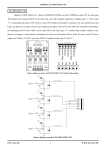
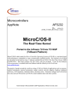
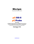
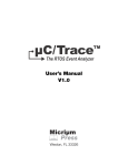
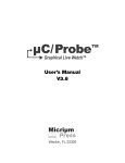
Micriµm
µC/OS-II and µC/Probe for the
NXP® LPC2478 CPU
1.
Introduction
This document, AN-1479, explains example code for using µC/OS-II and µC/OS-Probe with the
IAR LPC2478-SK Development board, as shown in Figure 1-1, which employs NXP‟s ARM7TDMI-based
LPC2478 microcontroller. The processor includes 512 kB on-chip flash memory and 64-kB SRAM in
addition to dedicated SRAM for the EMAC and DMA peripherals. Additionally, the chip includes serial
interfaces such as an internal 10/100 EMAC, USB device and host (with support for an external OTG
2
transceiver), two CAN channels, a SPI controller, two SSP controllers, four UARTs, and several I C and
2
I S interfaces . Additionally, the chip has a SD/MMC card interface, many general purpose I/O pins, and a
10-bit A/D converter.
The IAR LPC2478-SK board includes the following peripherals:
• LPC2478 device
• LCD 3.5" 320x200 24bit color TFT with
backlight and touch screen
• MP3 decoder DSP + codec VS1002D
• 3-axis digital accelerometer with 11 bit
accuracy
• 64M SDRAM
• USB host connector
• USB device connector
• IrDA transceiver
• PS2 keyboard connector
• 100 Mbit Ethernet
• CAN driver and connector
• RS232 with ICSP control
• SD/MMC card connector
• JTAG connector
• MICTOR TRACE connector
• Reset button
• 2 user buttons
• Trim pot
• UEXT connector
• Audio IN
• Audio OUT
• RTC battery
• RoHS
Ethernet
(for µC/TCP-IP )
RS-232
(for µC/Probe)
USB Device
(for µC/USB-Device)
USB Host
(for µC/USB-Host)
Front View
LCD Display
(for µC/ GUI)
Potentiometer
SD Card Slot
NXP® LPC2478
USB State/User
LEDs
Push Buttons
Back View
Figure 1-1. IAR LPC2478-SK Kickstart Kit
7